1
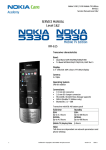
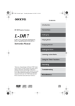
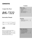
English
Contents
Home Theater Speaker System
HTP-L50
Instruction Manual
Thank you for purchasing the Onkyo home theater speaker
system.
Please read this manual thoroughly before using it.
Following the instructions in this manual will enable you to
obtain optimum performance and listening enjoyment from
your new home theater speaker system.
Please retain this manual for future reference.
Important Safeguards........................ 2
Precautions ....................................... 3
Supplied Accessories........................ 3
Feature .............................................. 4
Control positions and names ............ 4
Speaker placement............................ 5
Connecting the speakers ................... 6
Adjustment procedure ...................... 7
When using only the subwoofer
(SL-105)........................................ 7
Precaution on use.............................. 8
Troubleshooting guide...................... 8
Specifications ................................... 9
WARNING:
TO REDUCE THE RISK OF FIRE OR ELECTRIC SHOCK,
DO NOT EXPOSE THIS APPLIANCE TO RAIN OR
MOISTURE.
CAUTION:
TO REDUCE THE RISK OF ELECTRIC SHOCK, DO NOT
REMOVE COVER (OR BACK). NO USER-SERVICEABLE
PARTS INSIDE. REFER SERVICING TO QUALIFIED
SERVICE PERSONNEL.
WARNING
AVIS
RISK OF ELECTRIC SHOCK
DO NOT OPEN
RISQUE DE CHOC ELECTRIQUE
NE PAS OUVRIR
The lightning flash with arrowhead symbol, within an equilateral
triangle, is intended to alert the user to the presence of uninsulated
“dangerous voltage” within the product’s enclosure that may be of
sufficient magnitude to constitute a risk of electric shock to persons.
The exclamation point within an equilateral triangle is intended to
alert the user to the presence of important operating and maintenance
(servicing) instructions in the literature accompanying the appliance.
Important Safeguards
1. Read Instructions – All the safety and operating instructions
should be read before the appliance is operated.
2. Retain Instructions – The safety and operating instructions
should be retained for future reference.
3. Heed Warnings – All warnings on the appliance and in the
operating instructions should be adhered to.
4. Follow Instructions – All operating and use instructions
should be followed.
5. Cleaning – Unplug the appliance from the wall outlet before
cleaning. The appliance should be cleaned only as recommended by the manufacturer.
6. Attachments – Do not use attachments not recommended by
the appliance manufacturer as they may cause hazards.
7. Water and Moisture – Do not use the appliance near water –for
example, near a bath tub, wash bowl, kitchen sink, or laundry
tub; in a wet basement; or near a swimming pool; and the like.
8. Accessories – Do not place the appliance on an unstable cart,
stand, tripod, bracket, or table. The appliance may fall, causing
serious injury to a child or adult, and serious damage to the
appliance. Use only with a cart, stand, tripod, bracket, or table
recommended by the manufacturer, or sold with the appliance.
Any mounting of the appliance
should follow the manufacPORTABLE CART WARNING
turer’s instructions, and should
use a mounting accessory recommended by the manufacturer.
9. An appliance and cart combination should be moved with care.
Quick stops, excessive force,
and uneven surfaces may cause
the appliance and cart combinaS3125A
tion to overturn.
10. Ventilation – Slots and openings in the cabinet are provided
for ventilation and to ensure reliable operation of the appliance
and to protect it from overheating, and these openings must not
be blocked or covered. The openings should never be blocked
by placing the appliance on a bed, sofa, rug, or other similar
surface. The appliance should not be placed in a built-in installation such as a bookcase or rack unless proper ventilation is
provided. There should be free space of at least 20 cm (8 in.)
and an opening behind the appliance.
11. Power Sources – The appliance should be operated only from
the type of power source indicated on the marking label. If you
are not sure of the type of power supply to your home, consult
your appliance dealer or local power company.
12. Grounding or Polarization – The appliance may be equipped
with a polarized alternating current line plug (a plug having
one blade wider than the other). This plug will fit into the
power outlet only one way. This is a safety feature. If you are
unable to insert the plug fully into the outlet, try reversing the
plug. If the plug should still fail to fit, contact your electrician
to replace your obsolete outlet. Do not defeat the safety purpose of the polarized plug.
2
13. Power-Cord Protection – Power-supply cords should be
routed so that they are not likely to be walked on or pinched by
items placed upon or against them, paying particular attention
to cords at plugs, convenience receptacles, and the point where
they exit from the appliance.
14. Lightning – For added protection for the appliance during a
lightning storm, or when it is left unattended and unused for
long periods of time, unplug it from the wall outlet and disconnect the antenna or cable system. This will prevent damage to
the appliance due to lightning and power-line surges.
15. Overloading – Do not overload wall outlets, extension cords,
or integral convenience receptacles as this can result in a risk of
fire or electric shock.
16. Object and Liquid Entry – Never push objects of any kind
into the appliance through openings as they may touch dangerous voltage points or short-out parts that could result in a fire or
electric shock. Never spill liquid of any kind on the appliance.
17. Servicing – Do not attempt to service the appliance yourself as
opening or removing covers may expose you to dangerous voltage or other hazards. Refer all servicing to qualified service
personnel.
18. Damage Requiring Service – Unplug the appliance form the
wall outlet and refer servicing to qualified service personnel
under the following conditions:
A. When the power-supply cord or plug is damaged,
B. If liquid has been spilled, or objects have fallen into the
appliance,
C. If the appliance has been exposed to rain or water,
D. If the appliance does not operate normally by following the
operating instructions. Adjust only those controls that are
covered by the operating instructions as an improper
adjustment of other controls may result in damage and will
often require extensive work by a qualified technician to
restore the appliance to its normal operation,
E. If the appliance has been dropped or damaged in any way,
and
F. When the appliance exhibits a distinct change in performance – this indicates a need for service.
19. Replacement Parts – When replacement parts are required, be
sure the service technician has used replacement parts specified
by the manufacturer or have the same characteristics as the
original part. Unauthorized substitutions may result in fire,
electric shock, or other hazards.
20. Safety Check – Upon completion of any service or repairs to the
appliance, ask the service technician to perform safety checks to
determine that the appliance is in proper operation condition.
21. Wall or Ceiling Mounting – The appliance should be mounted
to a wall or ceiling only as recommended by the manufacturer.
22. Heat – The appliance should be situated away from heat
sources such as radiators, heat registers, stoves, or other appliances (including amplifiers) that produce heat.
23. Liquid Hazards – The appliance should not be exposed to
dripping or splashing and no objects filled with liquids, such as
vases should be placed on the appliance.
Precautions
For European model
1. Recording Copyright
Recording of copyrighted material for other than personal use is
illegal without permission of the copyright holder.
Declaration of Conformity
2. AC Fuse
The fuse is located inside the chassis and is not user-serviceable. If
power does not come on, contact your Onkyo authorized service station.
We, ONKYO EUROPE
ELECTRONICS GmbH
LIEGNITZERSTRASSE 6,
82194 GROEBENZELL,
GERMANY
declare in own responsibility, that the ONKYO product described
in this instruction manual is in compliance with the corresponding
technical standards such as EN60065, EN55013, EN55020 and
EN61000-3-2, -3-3.
3. Care
From time to time you should wipe the front and rear panels and the
cabinet with a soft cloth. For heavier dirt, dampen a soft cloth in a
weak solution of mild detergent and water, wring it out dry, and
wipe off the dirt. Following this, dry immediately with a clean cloth.
Do not use rough material, thinners, alcohol or other chemical solvents or cloths since these could damage the finish or remove the
panel lettering.
GERMERING, GERMANY
I. MORI
4. Power
ONKYO EUROPE ELECTRONICS GmbH
WARNING
BEFORE PLUGGING IN THE UNIT FOR THE FIRST TIME,
READ THE FOLLOWING SECTION CAREFULLY.
The voltage of the available power supply differs according to
country or region. Be sure that the power supply voltage of the area
where this unit will be used meets the required voltage (e.g., AC
230 V, 50 Hz or AC 120 V, 60 Hz) written on the rear panel.
For British model
Replacement and mounting of an AC plug on the power supply cord
of this unit should be performed only by qualified service personnel.
IMPORTANT
The wires in the mains lead are coloured in accordance with the
following code:
Blue : Neutral
Brown : Live
As the colours of the wires in the mains lead of this apparatus may
not correspond with the coloured markings identifying the terminals in your plug, proceed as follows:
The wire which is coloured blue must be connected to the terminal
which is marked with the letter N or coloured black.
The wire which is coloured brown must be connected to the terminal which is marked with the letter L or coloured red.
For Canadian model
For models having a power cord with a polarized plug:
CAUTION: TO PREVENT ELECTRIC SHOCK, MATCH
WIDE BLADE OF PLUG TO WIDE SLOT, FULLY INSERT.
IMPORTANT
Modèle pour les Canadien
A 5 ampere fuse is fitted in this plug. Should the fuse need to be
replaced, please ensure that the replacement fuse has a rating of 5
amperes and that it is approved by ASTA or BSI to BS1362. Check
for the ASTA mark or the BSI mark on the body of the fuse.
IF THE FITTED MOULDED PLUG IS UNSUITABLE FOR THE
SOCKET OUTLET IN YOUR HOME THEN THE FUSE
SHOULD BE REMOVED AND THE PLUG CUT OFF AND DISPOSED OF SAFELY. THERE IS A DANGER OF SEVERE
ELECTRICAL SHOCK IF THE CUT OFF PLUG IS INSERTED
INTO ANY 13 AMPERE SOCKET.
If in any doubt, please consult a qualified electrician.
Sur les modèles dont la fiche est polarisée:
ATTENTION: POUR ÉVITER LES CHOCS ÉLECTRIQUES, INTRODUIRE LA LAME LA PLUS LARGE DE LA
FICHE DANS LA BORNE CORRESPONDANTE DE LA PRISE
ET POUSSER JUSQU’AU FOND.
Supplied Accessories
Make sure your box contains everything listed below. The number of accessories is indicated in brackets.
• Subwoofer (SL-105) [1]
• Satelite speakers (D-L1) [5]
• Speaker cable for L/R front and
center speakers, 3.5 m [3]
(Red) (White) (Green)
• Spacers for subwoofer [4]
• Speaker cable for surround
speakers, 8 m [2]
• Spacers for satelite speakers [20]
• Pin cord [1]
(Blue) (Gray)
3
Feature
The HTP-L50 is a 5.1-channel speaker package that consists
of five satellite speakers and one subwoofer with an internal
amplifier.
The HTP-L50 features the SL-105 subwoofer with L/R
mixing circuits and a built-in cut-off filter as the subwoofer
and the D-L1 speakers with MDF (Medium Density
Fiberboard) cabinet and OMF-cone as the five satellite
speakers. Simply connect the speakers to your AV amplifier
or receiver for superb surround audio playback.
The speaker cables and satellite speaker terminals are colorcoded to facilitate connection. Connect each cable to the
matching-colored terminal.
Control positions and names
■ Subwoofer SL-105
Front panel
2
3
Rear panel
C
SL-105
SL-105
LINE
INPUT
SPEAKER LEVEL
+
POWERED SUBWOOFER
R
_
_
L
+
AUTO STANDBY
INPUT
FREQUENCY
FROM
AMP/RECEIVER
OUTPUT LEVEL
L
(MONO)
OFF
OUTPUT
+
50 Hz
200 Hz
MIN
ON
R
TO SPEAKERS
R
_
_
L
+
MAX
D
A B
POWER
1
1 POWER switch and indicator
Pressing this button turns the power on (the indicator
lights). Pressing the button again turns the power off (the
indicator goes out).
Red: Unit is in standby mode
Green: Unit is in operation
2 FREQUENCY knob
Use this knob to select the high-frequency range at which
you wish to cut off the signal to the subwoofer. You can
select any frequency between 50 Hz and 200 Hz depending
on the characteristics of the speaker system being used with
the SL-105.
3 OUTPUT LEVEL knob
Use this knob to adjust the output level of the subwoofer.
To AC outlet
A LINE INPUT jacks
Connect these jacks to the LINE OUT jacks of the
amplifier etc.
B AUTO STANDBY switch
This switch is used to turn on and off the auto standby
function.
ON: This activates the auto standby function.
If a constant level signal is not received from the amplifier
(or receiver) over a period of a few minutes, the SL-105
automatically enters the standby state. If a constant level
signal is later received from the amplifier (or receiver), the
power is automatically turned back on.
OFF: Deactivates the auto standby function.
Notes:
• The auto standby function operates on the existence or
absence of a constant level input signal. If the auto
standby function does not operate properly, try slightly
increasing (or decreasing) the output level of the
amplifier or receiver.
(Note that output levels of some amplifiers and receivers
cannot be adjusted. For more details regarding your
components, refer to the instruction manual supplied
with them.)
• If noise from peripheral components causes the incorrect
operation of the auto standby function, or if outputting
low volumes (i.e., during the nighttime) causes the auto
standby function to activate, turn off the auto standby
function.
• The auto standby function only operates while the power
switch for the SL-105 is turned on.
C SPEAKER LEVEL INPUT terminals
Connect these input terminals to the speaker output
terminals of your amplifier or receiver.
D SPEAKER LEVEL OUTPUT terminals
4
The speaker-level signal to the front speakers is output
from these terminals.
Speaker placement
■ Layout of your speaker system
■ Satellite speaker
Satellite speakers
• Front left/right speakers and center speakers
Installation using commercially-available stands and
fixtures
These three speakers should be placed in front of the
listener.
All three speakers should be placed at the same level.
Placement should be such so that the speakers all aim at the
ears of the listener when the listener is listening to music or
watching the screen. The center speakers enhance the sound
effects from the two front speakers and add clarity to
movements in the sound for a much richer sound image.
• Surround left/right speakers
Surround speakers should be placed to the side of the
listener or behind the listener. These speakers produce
sound movements in all directions, create a sound
environment that reflects the background, and create the
sensation of being in the middle of the action.
The speaker bottom and rear are equipped with screw holes so
that you can attach commercially-available stands or
mounting fixtures for a variety of mounting options. (Two M5
screw holes, 60 mm pitch on the bottom and one M5 screw
hole on the rear.)
Note:
When attaching an accessory item
to a speaker, be careful of the
length of the screws used. Use
only screws that provide the
required strength with a screw
length between 7 and 12 mm.
M5 screw
5 mm
7 to 12 mm
Subwoofer
The subwoofer can be installed anywhere in the room, but in
most situations you will obtain the best results by placing the
subwoofer to the side near a corner of the room. The quality
and level of the bass sounds from the subwoofer will differ
depending on the location where the subwoofer is placed and
the layout of the room, so it is recommended to place the
subwoofer in several locations and find the position that
provides the best results.
■ Using spacers
Attaching the supplied spacers is recommended for obtaining
the best sound quality. Also, by attaching the provided
spacers, the speakers will not slide easily for a more stable
installation.
• Positioning vertically
Spacer
Subwoofer
SL-105
Front left
speaker
D-L1
TV or
Screen
Center
speaker
D-L1
Bottom
of D-L1
Front right
speaker
D-L1
• Positioning horizontally
Spacer
Surround
right speaker
D-L1
Surround
left speaker
D-L1
Side
of D-L1
Listener
5
Connecting the speakers
For safety reasons, do not turn on any devices or components
until you have completed all wiring procedures.
■ Connecting the satellite speakers
Note:
The nominal impedance of this speaker system is 6 Ω. Use
only amplifiers capable of handling this impedance.
Front right
speaker
MODEL
Center
speaker
(RED)
D-L1
MODEL
D-L1
Front left
speaker
(GRN)
MODEL
D-L1
(WHT)
Green
Red
White
Surround right
speaker
SURROUND
SPEAKERS
L
R
MODEL
D-L1
Surround left
speaker
FRONT SPEAKERS
CENTER
L
R
(GRY)
MODEL
D-L1
• Connect the input terminals on the rear of the satellite
speakers to the speaker output terminals on the AV
amplifier or receiver using the supplied speaker cables as
shown in the diagram to the left.
• Each speaker cable should be connected to the speaker
terminal of the same color.
The speaker’s terminals are colored as follows.
Front left speaker (+)
: white
Front right speaker (+)
: red
Center speaker (+)
: green
Surround left speaker (+) : blue
Surround right speaker (+): gray
Notes:
• Make sure that the positive (+)
and negative (–) speaker cables
do not contact each other. If they
do, a short-circuit may occur,
causing damage to the amplifier.
• Be sure to connect the speaker cables with the correct
polarity (+ and –) and with the proper left-right speaker
orientation. If connected incorrectly, the resulting sound
space with sound unnatural.
• Pull the speaker cable lightly to ensure that it is connected
firmly.
(BLU)
■ Connecting the subwoofer
Gray
Blue
L
R
REMOTE
CONTROL
R
OUT
FRONT SPEAKERS
CENTER
L
R
AC INLET
FM 75
IN
MD/CDR/TAPE
VIDEO OUTPUT
Y
OPTICAL
IN
L
ANTENNA
AM
IN
SUB
WOOFER TV/LINE
DIGITAL
OUT
SURROUND
SPEAKERS
ANTENNA
PREOUT
AUDIO
S VIDEO
VIDEO
PB
PR
COMPONENT
When used together with an AV amplifier or receiver with
surround playback capabilities, be sure to connect its SUB
WOOFER PREOUT terminal to the subwoofer SL-105 using
the supplied pin-cord.
If you connect the subwoofer SL-105 using speaker cables,
depending on the settings at the AV amplifier or receiver, bass
signals may be cut for an unsatisfactory bass output. For more
details regarding connection procedures, refer to the manuals
that came with your AV amplifier or receiver.
L
R
REMOTE
CONTROL
R
AC INLET
VIDEO OUTPUT
Y
IN
FRONT SPEAKERS
CENTER
L
R
FM 75
IN
OUT
MD/CDR/TAPE
OPTICAL
OUT
L
ANTENNA
AM
IN
SUB
WOOFER TV/LINE
DIGITAL
Before connecting
SURROUND
SPEAKERS
ANTENNA
PREOUT
AUDIO
S VIDEO
VIDEO
PB
PR
COMPONENT
Prepare the supplied speaker cables as shown below.
(Supplied pin-cord)
PREOUT
AUDIO
Strip off the end of the
speaker cable insulation.
Twist together the exposed
wires strands.
SUB
WOOFER
SPEAKER LEVEL
+
R
_
_
L
+
LINE
INPUT
AUTO STANDBY
INPUT
Connecting to the speaker terminals
FROM
AMP/RECEIVER
L
(MONO)
OFF
OUTPUT
TO SPEAKERS
+
R
_
_
ON
R
L
+
Connect the SUB WOOFER PREOUT terminal on your AV
amplifier or receiver to the subwoofer rear panel using the
supplied pin-cord as shown in the diagram above.
Push down the lever.
6
Insert the
exposed wires
into the hole.
Release the lever.
Note:
If the amplifier has a subwoofer terminal, since its output is
monaural, connect it to the low level LINE INPUT L(MONO)
terminal on the subwoofer SL-105.
Adjustment procedure
■ Adjusting the cut-off frequency and volume
Use the cut-off frequency (FREQUENCY) and volume
(OUTPUT LEVEL) knobs on the front of the subwoofer (SL105) and adjust the levels to the desired level in accordance
with the layout of your room and the positioning of all your
components. If the playback frequency range and volume of
the subwoofer are not set to proper levels, distortions in the
playback characteristics can result.
POWERED SUBWOOFER
OUTPUT LEVEL
FREQUENCY
50 Hz
200 Hz
MIN
Although it is recommended to set the cut-off frequency and
output level settings as high as possible, it is difficult to notice
the extremely low frequency bass sounds. This makes it
possible to accidentally set the volume level too high. In order
to prevent this, back the levels down just a bit to ensure the
proper balance.
Note:
Make sure that the input levels do not reach excessive levels.
The HTP-L50 is designed for playing back music at a normal
volume, but if the input levels are set to enormous levels, it
may damage the speakers. Also, always first lower the volume
at the amplifier before changing the settings of any switches
to prevent accidental damage.
MAX
Recommended level for the HTP-L50 package system
When using only the subwoofer (SL-105)
■ Connection with a preamplifier
Preamplifier
Output terminals
L
To power amplifier
R
(Not supplied)
SPEAKER LEVEL
+
R
_
_
L
+
LINE
INPUT
AUTO STANDBY
INPUT
■ Connection to amplifier’s (receiver’s) speaker
terminals
1. Using speaker cables and the speaker cables that came
with your speakers, connect the SL-105’s SPEAKER
LEVEL INPUT terminals and the amplifier’s speaker
terminals.
2. Connect the Right and Left speakers to the SL-105’s
SPEAKER LEVEL OUTPUT terminals.
Amplifier
(Receiver)
Speaker (R)
Speaker_ terminals
_
FROM
AMP/RECEIVER
+
L
(MONO)
OFF
OUTPUT
TO SPEAKERS
+
R
_
_
Speaker (L)
R
L
+
L
+
ON
R
L
+
SL-105
SPEAKER LEVEL
Note:
With an ordinary preamplifier having two output channels,
connect both the Right and Left jacks.
+
R
_
_
LINE
INPUT
AUTO STANDBY
INPUT
FROM
AMP/RECEIVER
L
(MONO)
OFF
OUTPUT
TO SPEAKERS
+
R
_
_
ON
R
L
+
SL-105
For details on how to connect the speaker cables, see the
previous page.
Notes:
• When connecting the speaker cables, be sure not to mistake
the (+) and (–) and the L (left) and R (left). If the speaker
cables are connecting incorrectly, there will be a loss of
fidelity in the bass sound ranges.
• The speakers connected to the SL-105 SPEAKER LEVEL
OUTPUT terminals must have an impedance equal to or
greater than the rating indicated on the amplifier connected
to the SPEAKER LEVEL INPUT terminals. Otherwise,
amplifier damage may occur.
• Do not use BTL (Balanced Transformer-Less) type
amplifiers. Using a BTL amplifier may cause damage to
both the amplifier and the subwoofer. Ordinary amplifiers
are not BTL amplifiers. For details, see the amplifier’s
instruction manual.
7
Precaution on use
■ Placement
• The enclosure is made of wood and therefore sensitive to
extreme temperatures and humidity. Avoid placing the unit
in locations subjected to direct sunlight or in humid places
such as near an air conditioner, bathroom or kitchen, as
well as in locations subjected to soot or steam such as near
a kitchen table and humidifier. Otherwise, damage may
occur.
• Keep water or other liquids away from the unit. If water is
spilled into the unit, not only the unit but also the
connected amplifier (receiver) may be damaged.
• Place the unit on a level and rigid surface free from
vibration.
• Slip-proof spacers are provided with the SL-105. If the SL105 is to be placed on flooring or other similar surfaces,
attach these spacers to the bottom surface at the corners.
This will not only prevent scratching, but also provide a
stable footing. However, note that depending on the
surface, the spacers may leave markings.
• This unit is designed to be used in the upright vertical
position only. Do not use it in the horizontal or tilted
position.
• If the unit is used near a turntable or CD player, howling or
skipping of sound may occur. To prevent this, move the
unit away from the turntable or CD player or otherwise
lower the unit’s output level.
• This unit can handle the specified input power when it is
used for ordinary music reproduction. If the following
abnormal signals are fed to the unit, however, an
overcurrent may flow in the internal circuits, causing
burning or breakage of the wires even if the input power is
below the specified rating.
1. Special test signals produced by audio checking CD, etc.
2. Sound produced when connecting or disconnecting
audio connection cables.
(Always turn off the amplifier’s power before
connecting or disconnecting cables.)
3. Howling when a microphone is used.
4. Abnormal sound produced when bass-range signals are
excessively boosted by using the amplifier’s (receiver’s)
tone controls, a graphic equalizer, etc., or when a source
whose bass range is abnormally boosted is being played.
This state called “rattling” occurs when the signal is
beyond the driver’s reproduction capacity. Although it is
not a sign of damage, decrease the speaker output level
to prevent damage to the driver.
Troubleshooting guide
■ Subwoofer SL-105
Symptom
Cause
Remedy
The unit does not turn on.
• The power plug is not fully inserted.
• Insert the power plug fully into the power
outlet.
No sound output
• The OUTPUT LEVEL knob is set to the
MIN level.
• Pin-connector cable(s) are disconnected
at the LINE INPUT jacks.
• Speaker cables are not properly connected to the SPEAKER LEVEL INPUT
terminals.
• The speaker setting at the amplifier (or
receiver) is set to “Subwoofer No.”
• Set the OUTPUT LEVEL knob properly.
• The input signal is so small that the unit
entered the standby state.
Small sound output
Hum noise
• Connect cable(s) to the LINE INPUT jacks.
• Connect the speaker cables properly.
• Check the settings at the amplifier (or receiver).
• Slightly increase the output level at the amplifier (or receiver).
• Set the AUTO STANDBY switch to OFF.
• Speaker cables are connected to the
SPEAKER LEVEL INPUT terminals
with reversed phase.
• Playing source does not include
superbass sound.
• Connect the speaker cables properly.
• Pin-connector cable is not inserted
completely.
• External leakage flux (induction noise
by TV etc.) occurs.
• Fully insert the pin-connector cable.
• Play sources with superbass sound.
• Separate from the noise source and connect.
■ Satellite speaker D-L1
Symptom
No sound output
8
Cause
• Speaker cables are not properly connected.
Remedy
• Connect the speaker cables properly.
Specifications
■ Subwoofer SL-105
■ Satellite speaker D-L1
Type
Bass-reflex with built-in power
amplifier
Use
For superbass-range reproduction
Frequency response
30-200 Hz (at maximum crossover frequency)
Crossover frequency
50-200 Hz (variable)
Maximum output power
60 W
Input impedance
4.7 kΩ (for speaker-level input
terminals)
12 kΩ (for low-level input jacks)
Sensitivity
Speaker-Level 2 V
Line
45 mV
Speaker
20-cm woofer
Power supply
AC 120 V, 60 Hz
AC 220 - 230 V, 50/60 Hz
AC 230 - 240 V, 50 Hz
Power consumption
70 W (AC 120 V, 60 Hz)
42 W (AC 220 - 230 V, 50/60 Hz,
AC 230 - 240 V, 50 Hz)
Dimensions (W × H × D)
235 × 416 × 404 mm
9-1/4" × 16-3/8" × 15-7/8"
Weight
12.5 kg 27.6 lbs.
Others
AUTO STANDBY ON/OFF
(with CANCELLING Switch)
Type
Air suspension
Frequency response
125 Hz - 25 kHz
Maximum input power
30 W
Output sound pressure level 83 dB/W/m
Impedance
6Ω
Speaker
8-cm OMF cone
Cabinet capacity
0.6 L
Dimensions (W × H × D)
85 × 120 × 112 mm
3-3/8" × 4-3/4" × 4-7/16
Weight
0.7 kg 1.5 lbs.
Others
Magnetic shielding
Specifications and appearance may subject to change for improvement
without prior notice.
9
Sales & Product Planning Div. : 2-1, Nisshin-cho, Neyagawa-shi, OSAKA 572-8540, JAPAN
Tel: 072-831-8111 Fax: 072-833-5222 http://www.onkyo-intl.com
ONKYO U.S.A. CORPORATION
18 Park Way, Upper Saddle River, N.J. 07458, U.S.A.
Tel: 201-785-2600 Fax: 201-785-2650 http://www.onkyousa.com
ONKYO EUROPE ELECTRONICS GmbH
Liegnitzerstrasse 6, 82194 Groebenzell, GERMANY
Tel: +49-8142-4401-0 Fax: +49-8142-4401-555 http://www.onkyo.net
ONKYO CHINA LIMITED
Units 2102-2107, Metroplaza Tower I, 223 Hing Fong Road, Kwai Chung,
N.T., HONG KONG Tel: 852-2429-3118 Fax: 852-2428-9039 http://www.onkyochina.com
SN 29343437
HOMEPAGE
http://www.onkyo.co.jp/
I0208-1