1
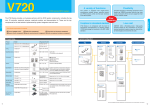
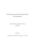
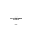
Electromagnetic Inductive RFID System V720-series User’s Manual Long-Range Antenna V720-HS04 Manual Number SRFM-006A About this Manual: Thank you for purchasing our V720-series Electromagnetic Inductive RFID System. The V720-series is a family of products that were developed by fully utilizing our high technology and broad experience. This Users Manual provides various information that will be necessary when using the V720-HS04 Antenna (hereinafter called the "Antenna"), including the functions and performance of the Antenna and how to use it. When you actually use the V720-series product, please make sure to follow the recommendations below: • Read this manual carefully to understand the product fully, and ensure proper use when you actually use the product. • Keep this manual in a safe place where you can access it any time for immediate reference. Precautions ii z z z ’ iii iv Safety Precautions This chapter provides important information for the safe use of this product. Ensure to read the information carefully before use. In the safety precautions below, severity is categorized as either ”WARNING” or “CAUTION”. WARNING Caution Indicates a potentially hazardous situation which, if not avoided, could result in minor or moderate injury, or may result in serious injury or death. Additionally there may be significant property damage. Indicates a potentially hazardous situation which, if not avoided, may result in minor or moderate injury, or property damage. Property damage refers to extended damage caused to house/household goods or livestock/pets. ●Description of Symbols Prohibition Indicates an action or activity not permitted. Observe strictly Indicates the need to ensure the safe use of the product. Ensure to establish a solid grounding A label indicating that a device with a grounding terminal should always be grounded. Electric shock hazard A notification that alerts the possibility of electric shock under certain conditions. Do not disassemble A notification that prohibits disassembly when injuries caused by electric shocks may result. Please ensure that all cautions and prohibitions are adhered to, since non-compliance may lead to serious injury or damage, in certain circumstances. v WARNING Never disassemble, repair, or modify the main unit and cables. z Do not disassemble, repair, or modify this product. Doing so may result in electric shock, fire, or personal injury. Do not handle the device with wet hands. Do not touch the terminals while the device is connected to the power supply. z Electric shock hazard. Do not allow the cables to be in contact with heaters. z The cable sheaths may melt and the exposed wire may cause electric shock or fire. Be sure to connect to a grounded main outlet for AC adapter power cord. z Not doing so may result in fire or electric shock hazard. Do not use the power cords and power adapters not supplied with the products. z Failure to do so may results in electric shock, fire, or personal injury. Connect and disconnect cables as described in the following procedures when installing, moving, on this product or attached devices. To connect: 1. Turn everything OFF. 2. Attached all cables to devices. 3. Attached power cords to outlet. To disconnect: 1. Turn everything OFF. 2. Remove power cords from outlet. 3. Remove all cables from devices. Failure to do so may result In spark or deform or damage the device. Caution Do not drop the device or apply physical shock. z Doing so may result in personal injury or device damage. Do not apply strong force to, or place heavy items on the device or cables. z Doing so may deform or damage the device, resulting in electric shock or fire. Do not lean against or otherwise apply excessive force to the Antenna body. z Doing so may result in personal injury or device damage. Use and store the product in an environment that is specified in the catalog or operation manual. z Failure to do so may cause failure of the device, electric shock, or fire. Do not use or store the device in the following locations: Locations that do not satisfy the specified operating conditions (-10 to +55 , 35%RH to 85%RH,non-condensing). Locations that do not satisfy the specified storage conditions (-25 to +65 , 35%RH to 85%RH,non-condensing). Locations where the Reader/Writer is exposed to direct sunlight. vi Locations where the Reader/Writer is exposed to dust, corrosive gas, saline, or flammable gas. Locations where the Reader/Writer is exposed to direct heat. Locations subject to condensation due to high humidity. Locations subject to vibration or impact that exceed the limits outlined in the specifications. Locations where the device may be exposed to water, oil, or chemical agents. (This applies to the models other than waterproof types.) Outdoor Be sure to tighten the devices screws securely. z Failure to do so may result in personal injury or device damage. Cables with screw attachments must be secured before use. z Failure to do so may damage the device. Use the spcified-size cables. z Failure to do so may result in electric shock or fire. To avoid interferences with other systems, adhere to the following items and check them before using the product. z The product uses a publicly available ISM frequency band of 13.56MHz to communicate with Tags. Some transceivers, motors, monitoring devices, power supplies (power supply ICs), and other similar RFID systems may generate noise, which cause radio interference and may affect communication with Tags. If the product is required in the vicinity of these items, check for any interferences prior to use. z On the contrary, the system itself may affect radio station transmissions or medical devices. Be cautious when using the system in the environments where such effects might occur. z To minimize noise effects, adhere to the following: Establish a Class D grounding (former Class 3 grounding) for metal objects placed in the vicinity of the system. Keep cables away from those with high voltages or heavy currents. Do not allow the device or cables to be exposed to water. z Doing so may result in electric shock, fire or failure of non-waterproof devices or cables. If the device fails or is exposed to water (non-waterproof devices or parts), or an unusual smell, smoke, or sparks are detected, immediately refrain from using the device and contact OMRON or a sales representative for service and repair. z Continued use of the failed device may result in electric shock or fire. Do not use damaged cables. z Continued use of the damaged cables may result in electric shock or fire. vii Precautions This chapter provides important information for international standards and copyright. Ensure to read the information carefully before use. Declarations V720-HS04 conforms to the following laws and standards. This conformity is effective only if V720-HS04 is used with the designated Reader/Writer, V720-BC5D4A or V720-BC5D4A-US. 1) European Standards (R&TTE Directive) Radio : EN 300 330-1,2 EMC : EN 301 489-1,3 Safety : EN61010 2) US standards (applicable only as a set of V720S-BC5D4A-US) FCC Part 15 Subpart C: 2006 FCC ID: OZGV720SBC5D4A-US FCC WARNING: Changes or modifications not expressly approved by the party responsible for compliance could void the user’s authority to operate the equipment. NOTICE: This equipment has been tested and found to comply with the limits for a Class A digital device, pursuant to part 15 of the FCC Rules. These limits are designed to provide reasonable protection against harmful interference when the equipment is operated in a commercial environment. This equipment generates, uses and can radiate radio frequency energy and, if not installed and used in accordance with the instructions, may cause harmful interference to radio communications. Operation of this equipment in a residential area is likely to cause harmful interference in which case the user will be required to correct the interference at his own expense. NOTICE: Attach the accompanying ferrite core to the cable of DC power supply at the side of AC Mains connected with AC input and Ground terminal in order to meet FCC emission limits. 3) Canadian standards (applicable only as a set of V720S-BC5D4A-US) RSS-Gen Issue 1: September 2005 RSS-210 Issue 6: September 2005 IC Number: 850L-72BC5D4A NOTICE: Operation is subject to the following two conditions: (1) this device may not cause, and (2) this device must accept any interference, including interference that may cause undesired operation of this device. ©Copyright OMRON Corporation 2006. All rights reserved. This document is protected by copyright and is intended solely for use in conjunction with the product. Notify your OMRON representative before copying or reproducing this document in any manner, for any other purpose. viii TABLE OF CONTENTS SECTION 1 Characteristics .................................................................1-1 1-1 Features .................................................................................................................... 1-2 SECTION 2 Specifications and Performance ......................................2-1 2-1 Antenna..................................................................................................................... 2-2 2-1-1 Nomenclature ....................................................................................................... 2-2 2-1-2 Specifications........................................................................................................ 2-2 2-1-3 Dimensions ........................................................................................................... 2-3 2-2 Cable ......................................................................................................................... 2-4 SECTION 3 Installation.......................................................................3-1 3-1 Installation of Antenna............................................................................................. 3-2 3-1-1 Installation Environment .................................................................................... 3-2 3-1-2 Mounting the Antenna......................................................................................... 3-3 SECTION 4 Reference Data.................................................................4-1 4-1 4-2 4-3 4-4 Communications Areas............................................................................................. 4-2 Influenceof Peripheral Metals at Antenna Installation .......................................... 4-3 Influence of Tag Angle .............................................................................................. 4-4 Effects of Materials on Tags ..................................................................................... 4-5 ix SECTION 1 Features 1-1 Features .............................................................................................................1-2 1-1 1-1 1-1 Features The V720–series Electromagnetic Inductive RFID System is ideal for the construction of highly functional, long–distance wireless ID systems for material control and logistics. The V720-HS04 Antenna is used by connecting it to the V720S-BC5D4A Reader/Writer using a coaxial cable with a special impedance of 50Ω. Long-Range antenna V720 -HS04 Long-Range Reader/Writer V720S-BC5D4A-US V720S-BC5D4A Antenna cable V720-A41-US V720-A41 For North America, the Antenna, V720-HS04, is supposed to connect to V720S-BC5D4A-US with V720-A41-US. Long-distance communication With the V720-D13P30 card-side's laminated Tag, the following long-distance communications are available: Approx. 50cm: When the V720S-BC5D4A Reader/Writer is connected to an output of 4W Wide-area communication Includes a wide 407mm×334mm Antenna panel and supports a wide communication area. The embedded Antenna coil is rectangular (size: 316mm×265mm). Antenna cable Complies with IP50 (IEC60529 standard). Highly weather-resistant, resinous material The highly weather-resistant, resinous material, PVC (Polyvinyl chloride) is used for the housing. 1-2 SECTION 2 Specifications and Performance 2-1 Antenna..............................................................................................................2-2 2-1-1 Nomenclature .................................................................................................2-2 2-1-2 Specifications..................................................................................................2-2 2-1-3 Dimensions .....................................................................................................2-3 2-1-4 Cable ...............................................................................................................2-4 2-1 2-1 Antenna 2-1 2-1 Antenna 2-1-1 Nomenclature • V720-HS04 2 1 No Name 1 BNC connector 2 Detection surface Description Connects the V720S-BC5D4A Reader/Writer to the Antenna connector for sending/receiving and to the exclusive coaxial cable (sold separately). Surface for communication with Tag Antenna coils are arranged along the rectangular frame. 2-1-2 Specifications General Specifications Item Specifications Resonance frequency Ambient operating temperature Ambient storage temperature Ambient operating humidity 13.56MHz -10 to +55°C (no freezing) -25 to +65°C (no freezing) 35 to 85% (with no condensation) Performance Specifications Item Insulation resistance Dielectric strength Vibration resistance Shock resistance 2-2 Specifications 20 MΩ min. between cable terminal and casing (with 500V DC mega) Leakage current of 1mA max. by applying 1000VAC, 50/60 Hz power for 1 minute between cable terminal and casing Durable at 10 to 150Hz Double amplitude less than 0.7mm 10 sweeps for 8 minutes each in 3 directions Durable at 150m/s2, 3 times In 3 directions Protective structure Input impedance Maximum input power Antenna gain IP50 (IEC60529 standard) 50Ω 4W -30dbi or lower Weight About 1.8kg 2-1 Antenna 2-1 2-1-3 Dimensions M ou nt in g ho le • V720-HS04 Unit: mm • Casing material Back board PVC PVC 2-3 2-1 Antenna 2-1 2-1-4 Cable (Sold separately) General specifications Model V720-A41 Antenna cable Item Cable type No. of leads Coaxial cable 2 (shield) 10MΩ or more between terminal and coating (with DC250V Mega) Insulation resistance AC300V/1min Withstand voltage Leak current: 1mA or less Coating material PVC Outer dimensions V720-A41 3.35M V720-A41 10.33M 3350 +20-30(mm) 10330+20-30(mm) Ф5.5(mm) Model Item Length (L1) 15 Connection label L1 Connector (Antenna side) ! Caution 2-4 Connector (Reader/Writer side) • Make sure to use the V720-A41 3.35M or V720-A41 10.33M Antenna cable. Otherwise, communication performance may diminish. • Do not change the cable length. Communication performance may be affected. • The BNC connector for the Antenna is not water-proof. SECTION 3 Installation 3-1 Installation of Antenna......................................................................................3-2 3-1-1 Installation Environment ................................................................................3-2 3-1-2 Mounting the Antenna .....................................................................................3-3 3-1 3-1 Installation of Antenna 3-1 3-1 Installation of Antenna 3-1-1 Installation Environment Installation Location It is assumed that this product is to be used indoors, or outdoors if there is a roof. Do not install the Antenna in the following locations. • Place exposed to direct sunlight. • The ambient temperature is not within a range between 10°C and 55°C or locations with radical temperature changes resulting in condensation. • The humidity is not within a range between 35% and 85%. • There is corrosive gas, flammable gas, dust, salt, or metal powder. • The Antenna will be subjected to direct vibration or shock. • Oil, or chemical will be sprayed onto the Antenna. • Vicinity of noise source. Peripheral environment 1) Influence of peripheral electronic devices Any peripheral electronic devices present may reduce communication range. Ambient noise can cause the communications range of the Antenna to drop. Ambient noise can be reduced by taking the following countermeasures. • Power Lines and High-tension Lines. Do not wire the Antenna cable along with high–tension lines or power lines. Keep the Antenna cable as far away as possible from them. • Inverters, Motors, and Other Driving Mechanisms. Be sure to ground the frames of driving mechanisms and keep them as far away as possible from the Antenna. • Switching Power Supplies. Be sure to ground switching power supplies and keep them as far away as possible from the Antenna. 2) Influence of peripheral metals Large metal objects around the Antenna may reduce communication distance; therefore, place such metal objects at least the following distances away from the Antenna: • Distance between back metal of Antenna and back surface of Antenna: 50cm or more. • Distance between side metal of Antenna and side of Antenna: 30cm or more. ! Caution 3-2 Before installation, perform sufficient tests following the above points. 3-1 Installation of Antenna 3-1 3-1-2 Mounting the Antenna Be sure to attach the provided bracket to the Antenna and mount the Antenna with four M6 screws with spring washers and flat washers as shown below. Spring washer Flat washer • Mounting Dimensional Drawing (H ole ) Influence of peripheral metals during Antenna installation Mutual interference in case of multiple Antenna installation Mount the Antenna at least 50cm away from the flat metal plate. If the Antenna is mounted only 20cm away, the communication distance will be 90% of the normal distance. For details, refer to 4-2 in Chapter 4. If the metal is not a flat plate but a rod, its influence will be smaller. Please verify the effects before installation. When mounting two or more Antennas in close proximity to each other, ensure that their communications areas do not overlap. For more details, refer to 4–1 Communications Areas. As a rough guide, when mounting Antennas in parallel or facing each other, ensure that the Antennas are separated by at least the dimensions shown below. Antennas in Parallel Keep 1m or more between antennas. Antennas Facing Keep 1.5m or more between antenna faces. 1.5m or more 3-3 SECTION 4 Reference Data 4-1 4-2 4-3 4-4 Communications Areas .........................................................................................4-2 Influence of Peripheral Metals at Antenna Installation......................................4-5 Influence of Tag Angle...........................................................................................4-3 Effects of Materials on Tags..................................................................................4-4 4-1 4-1 Communications Areas 4-1 4-1 Communications Areas The following diagram shows the communication area available when a standard Tag is used at ambient temperature, 25°C. The communication area varies depending on Antenna installation conditions, Tag forming conditions, Tag installation conditions and ambient temperature; therefore, verify the communication area beforehand. Since the coil in the Antenna is more or less rectangular (316mm×265mm), the horizontal communication distance slightly different from the vertical one. The Antenna surface and Tag surface are arranged in parallel. Tag to be tested: V720S-D13P01 Antenna Horizontal plane (H) Tag Vertical plane (V) cm * Following communication area is applicable for both functions; read and write. 60 50 40 30 20 10 0 50 40 30 20 10 0 10 20 30 40 50 cm Communication Area Communication Areas The communication area varies depending on Antenna installation conditions, Tag forming conditions, Tag installation conditions and ambient temperature; therefore, verify the communication area beforehand. 4-2 4-2 Influence of Peripheral Metals during Antenna Installation 4-2 4-2 Influence of Peripheral Metals of Antenna Installation Site Consider the influence of peripheral metals when installing the Antenna. Peripheral metals may greatly lower the communication distance for the Antenna. V720-HS04 to V720-D52P30/V720-D52P40 • Influence of back metals The following diagram shows the percentage of reduction in communication distance when a metal is mounted on the back of the Antenna. The horizontal axis in the diagram refers to the distance between the back of the Antenna and the metal plate, and the vertical axis refers to the relative communication distance on the assumption that the communication distance without mounting metals is 100, that is, the reduced percentage of the communication distance. Reduced percentage of the communication distance (%) Influence of back metals Distance between the back of the Antenna and the metal plate Y(mm) Influence of Peripheral Metals Peripheral metals may greatly lower the communication distance of the Antenna. Verify the communication performance and ensure it has enough read range beforehand if there is any metal object near the antenna installation site. 4-3 4-3 Influence of Tag Angle 4-3 4-3 Influence of Tag Angle The maximum communications range between the Antenna and Tag will be available if the face of the Antenna and the face of the Tag are parallel to each other. The communications range will be reduced if the Tag is mounted at an angle. Take the angle of the Tag into consideration when mounting. For reference, the relationship between the Tag angle and the communications range is illustrated in the graph below. The horizontal axis represents the angle between the face of the Antenna and the Tag with 0° representing the state where the faces are parallel. The vertical axis represents the relative communications range from when the angle is 0° and the communications range is 100% (i.e., the percentage reduction in communications range). V720–HS04 to V720–D52P30/V720–D52P40 • Communications Range vs. Tag Angle Test Setup Center of Antenna coil Tag V720-D52P30/ V720-D52P40 θ Antenna V720-HS04 4-4 4-4 Effects of Materials on Tags 4-4 4-4 Effects of Materials on Tags Take into consideration the effects of the mounting location when mounting the Tag. Communications range may be reduced if the Tag is near certain objects. The extent to which the distance will decrease depends on the actual material and its shape. Check the back of the Tag for the effects of metal and resin objects. Communications range as percentage of maximum communications range V720–HS04 to V720–D52P30/V720–D52P40 • Effect of Metal Objects The graph below shows the percentage reduction in communications range when a metal object is mounted behind the Tag. The horizontal axis represents the distance between the metallic plate and the Tag. The vertical axis represents the percentage decrease in communications range, where communications range with no metal object interference is taken to be 100%. Range between metallic plate and back of Tag (mm) • Effect of Resin Objects The following table shows the results of measuring the communications range when the Tag is mounted to a resin object. The extent to which the distance will decrease depends on the actual resin material and its shape. Material (shape) Bakelite (100 mm x 100 mm x 5 mm) Acrylic resin (100 mm x 100 mm x 2 mm) Polyethylene (100 mm x 100 mm x 2 mm) 4-5 Communications range 70% 80% 88% 4-4 Effects of Materials on Tags Test Setup • Metal Object 4-4 • Resin Object Resin Material: Aluminum plate (thickness = 2.0 mm) Dimensions: 240 x 190 mm 4-6 Revision History A manual revision code appears as a suffix to the catalog number on the front cover of the manual. SRFM- 002A Revision code The following table outlines the changes made to the manual during each revision. Page numbers refer to the previous version. Revision code Date 1 September, 2006 Revised content First Edition (New issued for Rohs Directive) OMRON CORPORATION RFID BUSINESS DEVELOPMENT DEPARTMENT 14th Fl., Gate City Osaki West Tower 1-11-1 Osaki, Shinagawa-ku, Tokyo 141-0032 Japan Tel: (81)3-5435-2016/Fax: (81)3-5435-2017 Regional Headquarters OMRON ELECTRONICS LLC 1920 Thoreau Drive Suite 165 Schaumburg, IL 60173 U.S.A. Tel: (1)847-303-0780/Fax: (1)847-925-1260 OMRON EUROPE B.V. Wegalaan 57, NL-2132 JD Hoofddorp The Netherlands Tel: (31)23-568-1200/Fax: (31)23-568-1222 OMRON ASIA PACIFIC PTE. LTD. 83 Clemenceau Avenue, #11-01, UE Square, 239920 Singapore Tel: (65)835-3011/Fax: (65)835-2711 OMCC: OMRON (CHINA) CO., LTD. Rm.302, AZIA Center, 1233 Lujiazui Ring Road Pudong New Area, Shanghai 200120, PRC. Tel: (86)21-5888-1666 Fax: (86)21-58888-7633/7933 Up-to-date information on RFID Systems can be accessed at OMRON's web site at http://www.omronrfid.com/ Authorized Distributor: Manual No. SRFM-006A Note: Specifications subject to change without notice. Printed in Japan