1
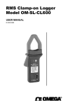
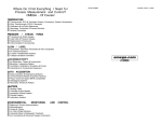
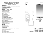
R
FL45200A Series
In-Line Flowmeters with
Half Union Adapters
R
R
An OMEGA Technologies Company
Operator’s Manual
www. Omega.com
Page 1
R
An OMEGA Technologies Company
Servicing USA and Canada: Call OMEGA Toll Free
USA
Canada
OneOmega Drive, Box 4047
Stamford,CT 06907-0047
Telephone:(203) 359-1660
FAX: (203)359-7700
976 Bergar
Laval (Quebec)H7L 5A1
Telephone:(514) 856-6928
FAX: (514) 856-6886
Sales Service: 1-800-826-6342 / 1-800-TC-OMEGASM
Customer Service: 1-800-622-2378 / 1-800-622-BESTSM
Engineering Service: 1-800-872-9436 / 1-800-USA-WHENSM
TELEX: 996404 EASYLINK: 62968934 CABLE: OMEGA
Servicing Europe: United Kingdom Sales and Distribution Center
25 Swannington Road, Broughton Astley, Leicestershire
LE9 6TU, England
Telephone: 44 (1455) 285520 FAX: 44 (1455) 283912
The OMEGA Complete Measurement and
Control Handbooks & Encyclopedias
Temperature
Pressure, Strain & Force
Flow and Level
pH and Conductivity
Data Acquisition Systems
Electric Heaters
Environmental Monitoring
and Control
Call for your FREE Handbook Request Form Today (203) 359-RUSH
Page 2
CAUTION
FOLLOW INSTRUCTIONS TO AVOID FAILURE
1. Finish piping to be plumb and true.
2. Polysulfone and other exotic plastics cannot tolerate P.V.C. glue and pipe
dope. Even the fumes can cause crazing.
3. Use teflon tape for threaded joints.
4. Make up assembly and fit pipes, then: remove F.M. after glue fumes are
vented out.
5. Meter cannot support attached pipes.
6. Excessive vibration may cause float to give poor reading or cause possible
fracture.
7. Wall, floor, and ceiling mounts to be carefully aligned and sturdy. A support
should be at top and bottom of meter. See drawing.
8. Hand tighten union nuts. No wrenches.
9. Protect meter from ultra violet (UV) rays.
10. VALVES - avoid system that will impose a sudden burst of flow to the meter.
Such a burst will cause the float to impact the guide assembly with destructive
force. Magnet, solenoid, or other quick opening valves cannot be used unless
meter is protected against sudden burst of flow.
11. Failure to comply VOIDS WARRANTY!
Calibration
Part Number
Part Number
(316 SS Float)
(Hastelloy C Float)
GPM
LPM
SCFM
M3/HR
FL45201A*
-
2-20
8-78
-
-
FL45202A
FL45202A-HL
6-60
30-230
-
-
FL45203A
FL45203A-HL
8-80
30-300
-
-
FL45204A
FL45204A-HL
6-100
20-380
-
-
FL45205A
FL45205A-HL
20-130
80-500
-
-
FL45206A
FL45206A-HL
25-175
100-675
-
-
FL45230A
-
-
-
40-240
70-400
* Teflon® float
Page 3
PARTS LIST
1
Key Part Number Description
2
3
4
5
1.
F-452004N
Lock Nuts
2.
F-452330N
Adaptor
3.
F-452002
Wireholder
4.
F-452043N
O-ring
6
5.
*Float
7
6.
*Meterbody
8
7.
F-452287N
Guide Wire
8.
F-452332N
Float Stop
*Float & Meterbody must be ordered
as a kit.
Materials of Construction
4-5/8 in.
(117.5 mm)
Meter Body:
Float:
Guide rod:
Adapters:
Wireholder:
Float Stop:
Union Nuts:
O-Rings:
Scale:
Accuracy:
18-7/8 in.
(479.4 mm)
Polysulfone
#316 Stainless Steel or Teflon or
Hastelloy C-276 (Based on model)
# 316 Stainless (opt. Hastelloy C-276)
Polysulfone
Polysulfone
Polyethylene
Nylon
Viton
Permanent, dual scale silkscreen (black ink)
± 2% of full scale reading
Your OMEGA FL45200A Series
! Your OMEGA flowmeter was designed to be easy to install.
! Please read the Instruction Guideline on the next page
before installing your flowmeter.
! This flowmeter is an instrument, special care should be taken
when handling and installing.
Page 4
INSTALLATION INSTRUCTIONS
Remember that you are installing an instrument. Adapters and fittings
should be tightened only enough to prevent leaking. Over tightening
may damage the o-ring seals and threaded fittings.
Never hold the meterbody with pliers or similar tools that may scratch.
Never allow the flowmeter to support the weight of related pipe or
tubing.
Be certain the meterbody is properly aligned with existing plumbing.
Misalignment will put excessive stress on the meterbody and may
result in damage and a decrease in the maximum pressure. If in doubt
regarding proper plumbing procedures, consult a licensed plumber.
The flowmeter must be installed in an exact vertical plane to ensure
accuracy.
Polysulfone is adversely affected by ultraviolet light. Protect the
flowmeter from direct sunlight.
Always use teflon® tape thread sealant. DO NOT use pipe dope
compounds as these products may cause crazing and cracking on the
meterbody.
Do not use solvent based glued (such as PVC cement) while the
flowmeter is fully installed. When using these glues, remove the
meterbody until the glue has cured. Then purge the system before
installing the unit.
Never attempt to solder brass fittings while the flowmeter is fully
installed. The heat required for soldering can damage the flowmeter.
Caution should be exercised when using ball type valves. In some
cases when the valve is opened the float can slam to the top of the
meter causing damage. This “Water Cannon” effect is actually
exceeding the maximum pressure and is not covered under warranty.
Your flowmeter had been designed to be virtually maintenance free.
Should your unit need occasional cleaning, use a mild soap and soft
bottle brush.
Be sure to note the floats “UP” position before disassembling the meter.
Page 5
Caution: Follow these instructions to avoid
failure.
Ceiling
3
Danger: Wear eye protection when
installing or removing flowmeter.
1. Polysulfone and other exotic plastics
cannot tolerate PVC Glue and /or pipe dope.
1
2
even fumes can cause crazing.
2. If you are installing your flowmeter to
a glued pipe configuration, install
3
flowmeter after all glued fittings are dried
and lines are purged of all fumes.
Use Teflon® tape (or similar) for the
3
flowmeters threaded adapters.
5
4
Hand tighten union nuts. No wrenches.
3. Wall, floor, and ceiling mounts are to
be carefully aligned and sturdy. Wall,
Floor
floor, and ceiling supports are recommended as needed.
4. Valves - Avoid a system that will impose a sudden burst of flow to the meter. Such
a burst will cause the float to impact the float stop with destructive force. Magnet,
solenoid, or other quick opening valves cannot be used unless meter is protected
against sudden bursts of flow.
5. The maximum working pressure should not exceed 150 psi at ambient
temperature.
Temperature
Maximum Temperature vs. Pressure
200°F / 93.3°C
190°F / 87.8°C
180°F / 82.2°C
170°F / 76.7°C
160°F / 71.1°C
150°F / 65.6°C
140°F / 60.0°C
130°F / 54.4°C
120°F / 48.9°C
110°F / 43.3°C
100°F / 37.8°C
90°F / 32.2°C
80°F / 26.7°C
70°F / 21.1°C
0/0
25 / 1.7
50 / 3.4
75 / 5.2
PSIg / BAR
100 / 6.9
125 / 8.6
150 / 10.3
MADE
IN
USA
WARRANTY
OMEGA warrants this unit to be free of defects in materials and workmanship and to give
satisfactory service for a period of 13 months from date of purchase. OMEGA Warranty adds
an additional one (1)month grace period to the normal one (1) year product warranty to
cover handling and shipping time. This ensures that OMEGA’s customers receive maximum
coverage on each product. If the unit should malfunction, it must be returned to the factory for
evaluation. OMEGA’s Customer Service Department will issue an Authorized Return (AR)
number immediately upon phone or written request. Upon examination by OMEGA, if the unit
is found to be defective it will be repaired or replaced at no charge. However, this
WARRANTY is void if the unit shows evidence of having been tampered with or shows
evidence of being damaged as a result of excessive corrosion; or current, heat, moisture, or
vibration; improper specification; misapplication; misuse or other operating conditions outside
of OMEGA’s control. Components which wear or which are damaged by misuse are not
warranted. These include contact points, fuses, and triacs.
OMEGA is glad to offer suggestions on the use of it’s various products. Nevertheless,
OMEGA only warrants that the parts manufactured by it will be as specified and free of
defects.
OMEGA MAKES NO OTHER WARRANTIES OR REPRESENTATIONS OF ANY KIND
WHATSOEVER, EXPRESSED OR IMPLIED, EXCEPT THAT OF TITLE AND ALL IMPLIED
WARRANTIES INCLUDING ANY WARRANTY OF MERCHANTABILITY AND FITNESS
FOR A PARTICULAR PURPOSE ARE HEREBY DISCLAIMED.
LIMITATION OF LIABILITY: The remedies of purchaser set forth herein are exclusive
and the total liability of OMEGA with respect to this order, whether based on contract,
warranty, negligence, indemnification, strict liability or otherwise, shall not exceed the
purchase price of the component upon which liability is based. In no event shall
OMEGA be liable for consequential, incidental or special damages.
Every precaution for accuracy has been taken in the preparation of this manual; however,
OMEGA ENGINEERING, INC. Neither assumes responsibility for any omissions or errors
that may appear nor assumes liability for any damages that result from the use of the
products in accordance with the information contained in this manual.
SPECIAL CONDITION
CONDITION:: Should this equipment be used in or with any nuclear installation or
activity, purchaser will indemnify OMEGA and hold OMEGA harmless from any liability or
damage whatsoever arising out of the use of the equipment in such a manner.
RETURN REQUESTS / INQUIRIES
Direct all warranty and repair requests/inquiries to the OMEGA ENGINEERING Customer
Service Department. BEFORE RETURNING ANY PRODUCT(S) TO OMEGA, PURCHASER
MUST OBTAIN AN AUTHORIZED RETURN (AR) NUMBER FROM OMEGA’S CUSTOMER
SERVICE DEPARTMENT (IN ORDER TO AVOID PROCESSING DELAYS). The assigned AR
number should then be marked on the outside of the return package and on any
correspondence.
FOR WARRANTY RETURNS, please have
The following information available
Before contacting OMEGA:
1. P.O. number under which the product
was PURCHASED,
2. Model and serial number of the product
under warranty, and
3. Repair instructions and/or specific
Problems relative to the Product
FOR NON WARRANTY REPAIRS OR
CALIBRATION, consult OMEGA for
current repair/calibration charges. Have
the following information available
before contacting OMEGA:
1. P.O. Number to cover the COST of
the repair/calibration,
2. Model and serial number of product,
and
3. Repair instructions and/or specific
Problems relative to the product.
OMEGA’s policy is to make running changes, not model changes, whenever an improvement is possible.
This affords our customers the latest in technology and engineering.OMEGA is a registered trademark of
OMEGA ENGINEERING, INC.©Copyright 1995 OMEGA ENGINEERING, INC. All rights reserved. This
documentation may not be copied, photocopied, reproduced, translated, or reduced to any electronic
medium or machine-readable form, in whole or in part, without written consent of OMEGA
ENGINEERING, INC.
Where Do I Find Everything I Need For
Process Measurement and Control?
OMEGA... Of Course!
Shop on line at www.Omega.com
TEMPERATURE
Thermocouple, RTD & Thermistor Probes, Connectors, Panels & Assemblies
Wire: Thermocouple, RTD & Thermistor
Calibrations & Ice Point References
Recorders, Controllers & Process Monitors
Infrared Pyrometers
PRESSURE / STRAIN FORCE
Transducers & Strain Gauges
Load Cells & Pressure Gauge
Displacement Transducers
Instrumentation & Accessories
FLOW / LEVEL
Rotameters, Gas Mass Flowmeters & Flow Computers
Air Velocity Indicators
Turbine / Paddlewheel Systems
Totalizers & Batch Controllers
pH / CONDUCTIVITY
pH Electrodes,Testers& Accessories
Benchtop / Laboratory Meters
Controllers, Calibrators, Simulators & Pumps
Industrial pH & Conductivity Equipment
DATA ACQUISITION
Thermocouple, RTD & Thermistor Probes, Connectors, Panels & Assemblies
Wire: Thermocouple, RTD & Thermistor
Calibrations & Ice Point References
Recorders, Controllers & Process Monitors
Infrared Pyrometers
HEATERS
Heating Cable
Cartridge & Strip Heaters
Immersion & Band Heaters
Flexible Heaters
Laboratory Heaters
ENVIRONMENTAL MONITORING AND CONTROL
Metering & Control Instrumentation
Refractometers
Pumps & Tubing
Air, Soil & Water Monitors
Industrial Water & Wastewater Treatment
pH, Conductivity & Dissolved Oxygen Instruments
M-2062/0904