1
TCIC User’s Manual
1. Main Features
2. Installation
3. TCIC-Monitor
3.1
Title
3.2
Menus
3.2.1
File
3.2.1.1
Exit
3.2.2
Setup
3.2.2.1
Card Settings
3.2.2.2
TCIC-Monitor Settings
3.2.2.3
Calibration and Defaults
3.2.2.4
Card Address
3.2.2.5
View All Settings (Read Only)
3.2.3
Library
3.2.3.1
Load
3.2.3.2
Save
3.2.3.3
Delete
3.3
"Outputs" Box
3.4
"Save to File" Command ('Start' or 'Stop')
3.5
Channel Boxes
3.5.1
Channel Title
3.5.2
Digital Display
3.5.3
Analog Display
3.5.4
Channel Description
3.5.5
"Show Graph" Command
3.6
Cold Junction Temperature
4. Command Set
4.1
Requesting Data
4.2
Change Output Status
4.3
Setpoint Configuration
4.4
Sample Program
4.5
Troubleshooting
5. Multi-Card System
6. USB, RS232 & RS485
7. Specifications
8. LabVIEW Sample
1
TCIC User’s Manual
1. Main Features
• Very High Speed & High Resolution.
• Supports up to 8 channels (differential inputs).
• Each channel can be set for a thermocouple reading or
for a voltage (millivolt) reading.
• Internal A/D resolution: 24 bit (not all are used).
• Sampling rate: 400 Hz (50 Hz for each channel).
• Single opto-isolated output per channel which can be
used as a set-point (alarm etc.) or as a general purpose
output.
• Conversion tables are on board to enable stand-alone
operation.
• Reading is in °F, °C or mV.
• CJC (Cold Junction Compensation) built on board.
• Each channel supports the most popular families of
thermocouples (E, J, K, R, S, T) or any indefinite voltage
source in the range -500mV -> +500mV.
• USB as a standard method of communication.
• USB + RS485 and RS232 (option).
• Multiple boards may be connected via USB or the
optional RS485.
• On board high accuracy reference voltage for easy
calibration.
• No need for external power supply when used with USB.
• Includes Windows software for initial setup and also a
Smart data logger package for monitoring & collecting
readings in high speed – with graphic mode display.
Communication
Two types of drivers are available:
• The direct driver provides access via a DLL supplying
functions to directly control the device.
• The VCP (Virtual COM Port) driver would make the TCIC
appear as a spare COM port on the PC, e.g. COM3.
2
TCIC User’s Manual
Setpoints
Each channel may be defined as a setpoint, which means that
the corresponding output will turn on upon crossing some level.
The setpoint user-defined selection also controls the direction of
the ‘setpoint indication’; that is, turn the output on upon crossing
the limit either upwards or downwards. In other words, the
direction of the trigger is user-defined. Likewise, the user may
define a hysteresis behavior, e.g., the output turns on when the
temperature goes above some limit and only goes off again when
the temperature falls below another (lower) limit, thus eliminating
undesirable fluctuations in the status of the output.
3
TCIC User’s Manual
2. Installation
(The following description refers to Windows XP. Obviously, on
another operating system it might be different.)
1. Make sure that all package files have been copied – and
unzipped if necessary – to your hard disk.
2. Two types of drivers are available. Install the one that
meets best your requirements. Note that only one
driver may be installed at the same time. That is, if
for some reason you want to switch to the other driver,
first uninstall the retired one.
• The direct driver provides access via a DLL supplying
functions to directly control the device.
• The VCP (Virtual COM Port) driver would make the
TCIC appear as a spare COM port on the PC, e.g.
COM3.
Consider which driver is best for you and proceed
accordingly to step 3 or 4.
3. Installing the Direct DLL Driver:
3.1 If the VCP (Virtual COM Port) Driver is installed,
uninstall it as follows:
Click: Start – Control Panel – Add or Remove Programs –
FTDI USB Serial Converter Drivers – Change/Remove
Disconnect all TCIC boards from the USB port and click
Continue…
4
TCIC User’s Manual
Click Finish.
3.2 Disconnect or disable the internet communication if
such exists. The reason for that is that there are cases
where the installation procedure automatically
communicates with manufacturer’s site, which might lead
to wrong operation.
3.3 Connect the TCIC card to your PC.
3.4 The ‘Found New Hardware Wizard’ appears.
Select the last option like this:
5
TCIC User’s Manual
3.5 Press Next and select the second option:
3.6 Press Next and browse to the Direct DLL driver folder:
6
TCIC User’s Manual
3.7 Click Next…
3.8 Press Continue Anyway…
7
TCIC User’s Manual
Click Finish – that’s it!
8
TCIC User’s Manual
4. Installing the VCP (Virtual COM Port) Driver:
4.1 If the Direct DLL Driver is installed, uninstall it as
follows:
Click: Start – Control Panel – Add or Remove Programs –
FTDI FTD2XX USB Drivers – Change/Remove
Disconnect all TCIC boards from the USB port and click
Continue…
Click Finish.
4.2 Connect the TCIC card to your PC.
9
TCIC User’s Manual
4.3 The ‘Found New Hardware Wizard’ appears.
Select the last option like this:
4.4 Press Next and select the second option:
10
TCIC User’s Manual
4.5 Press Next and browse to the VCP driver folder:
4.6 Click Next…
11
TCIC User’s Manual
Click
‘Finish’ – that’s it!
Notes
1. It might occur that the wizard will return to step 4.3, requiring to
repeat the process. This is normal, just repeat steps 4.3-4.6.
2. The package includes also an RS232 terminal found on the
Web, called Termite, through which the TCIC may be
communicated when the VCP driver is installed.
Termite (http://www.compuphase.com/software_termite.htm) is freeware, yet it
is easy to use and easy to configure.
TCIC communication parameters are:
Baud Rate: 115,200; Data: 8 bits; Parity: None; Stop Bits: 1.
12
TCIC User’s Manual
3. TCIC-Monitor
The TCIC-Monitor utility is an initial setup tool and a smart data
logger package for monitoring & collecting readings in high
speed, including graphic mode display. The TCIC-Monitor works
with both driver types (refer to section 1 - Main Features /
Communication). It detects which driver type (direct or VCP) is
installed and communicates with the card(s) using that driver
(the type of the driver detected is reported in the title). More
than one TCIC board may be connected to the PC while using
the TCIC-Monitor; the user should select the required board. It
is legitimate to run the TCIC-Monitor twice (or more) selecting
each time another free board. Likewise, when no free board is
detected, the TCIC-Monitor lets the user to work in ‘Demo’
mode.
Note: The TCIC-Monitor was developed under ‘.NET’ (dot NET), so
it requires the ‘dotnet framework’ V1.1.4322 in order to run. The
setup for this ‘dotnet framework’ is available free via Microsoft site;
however, to facilitate the process, it is included in the attached
CD-ROM (named dotnetfxV1.1.4322.exe).
13
TCIC User’s Manual
The markings in the screenshot below show the section where each
part of the display is described.
14
TCIC User’s Manual
3.1 Title
This main title shows the versions of the TCIC-Monitor and of the
card. For example, the title in the above screenshot indicates that
the version of the TCIC-Monitor is 1.03, while card’s version is 2.01.
3.2 Menus
The menus enable various operations, as described below.
3.2.1 File
3.2.1.1 Exit
Leaves the TCIC-Monitor program.
3.2.2 Setup
3.2.2.1 Card Settings
Adjusts the settings that reside in the card (on its non-volatile
memory).
The settings at a glance:
Common Setting
Temperature Unit:
°C / °F
Channel Settings
Channel Name:
... (view only)
Input Type:
None / TC-E / TC-J / TC-K /
TC-R / TC-S / TC-T / mV
Output Mode:
SP-Auto / SP-Latch / Manual
Set Points Switch
On:
...
Off:
...
15
TCIC User’s Manual
The settings in detail:
Common Setting
The following is a common setting for all the channels:
Temperature Unit:
°C / °F
Selects the temperature unit for all channels whose ‘Input
Type’ is defined as a thermocouple, i.e., TC-E, TC-J, TC-K, TCR, TC-S, or TC-T. In other words, this setting has no effect on
channels whose ‘Input Type’ is mV (or None).
Channel Settings
The following are individual settings for each channel:
Channel Name:
... (view only)
The user may assign a name to each channel.
This ‘Channel Name’ is actually a part of the ‘TCIC-Monitor
Settings’ (section 3.2.2.2); it does not reside in the card.
Though, for convenience's sake, the ‘Channel Name’ is shown
in the ‘Card Settings’ display, but restricted to ‘view only’.
None / TC-E / TC-J / TC-K /
TC-R / TC-S / TC-T / mV
Each channel may be referred to as one of three main types:
* Channel not in use (‘None’).
In this case channel’s description (section 3.5.4) will show
‘Not in Use’ regardless of the input coming in that channel.
* Channel represents a thermocouple whose type is one of
the six supported ones (E, J, K, R, S, or T). The card
converts the sampled voltage to degrees (°C or °F), taking
into account the cold junction temperature. So, the
readings passed by the card are in degrees (°C or °F);
the TCIC-Monitor shows these readings (in the displays
and in the graph) in degrees either. In case the card
detects that no thermocouple is connected, it reports
it to the PC, so the TCIC-Monitor displays ‘OPEN’
in that case.
* Channel represents an indefinite source of voltage, to be
reported in millivolts (mV), not in degrees. In this case,
there is no ‘OPEN’ indication when a channel is
disconnected.
Input Type:
16
TCIC User’s Manual
Output Mode:
SP-Auto / SP-Latch / Manual
This is actually ‘output x’ setting rather than ‘channel x’
setting. This setting defines the nature of output x
(x=1,2,...,8):
Roughly speaking, output x may be either a ‘setpoint
indicator’ of channel x, or a manual output with no
relation to channel x (nor any other channel).
‘Manual output’ simply means that the output can be turned
on or off directly by the host PC by simple software commands.
The ‘setpoint indicator’ definition, however, is more
complicated:
The main idea is that when output x is defined as a ‘setpoint
indicator’ (SP-Auto or SP-Latch), it will go high (on) when
input x crosses the ‘Set Points Switch / On’ limit. Now, there
are still some points to clarify:
The user may define two characteristics of the setpoint
indication:
* How will the indication stop (i.e., output goes ‘off’)?
Automatically or manually?
٠ Selecting ‘SP-Auto’ means automatic stop of the
indication. The ‘turn off’ operation will occur when input x
crosses the ‘Set Points Switch/Off’ limit. That mechanism
enables the user to define a hysteresis eliminating
undesirable fluctuations in the status of the output.
٠ Selecting ‘SP-Latch’ means that once there is ‘setpoint
indication’ (output is on), the output will stay on until
manually turned off by the TCIC-Monitor.
* The direction of temperature change that will trigger the
indication: Will the indication be supplied upon crossing
the ‘On’ limit upwards or downwards? This
characteristic is controlled by the ‘Set Points Switch/Off’
limit, as described below.
17
TCIC User’s Manual
Set Points Switch
On:
...
Defines the limit that upon its crossing output x will go
high (on) signaling a ‘setpoint indication’.
Off:
...
1. Defines the direction of temperature change that will
trigger the indication:
Off < On means indication upon crossing the On limit
upwards.
Off > On means indication upon crossing the On limit
downwards.
2. When Output Mode = ‘SP-Auto’, the Off limit plays one
more role:
It defines the hysteresis, i.e., the limit where the output
will go low (off) again.
To make the above description more comprehensible,
some examples follow:
Example 1:
Output Mode = ‘SP-Auto’, ‘On’ = 100°, ‘Off’ = 90°.
The output will go high (on) when the temperature rises
from 99° to 100°, and back low (off) upon falling from
91° to 90°.
Example 2:
Output Mode = ‘SP-Auto’, ‘On’ = 100°, ‘Off’ = 110°.
The output will go high (on) when the temperature falls
from 101° to 100°, and back low (off) upon rising from
109° to 110°.
Example 3:
Output Mode = ‘SP-Latch’, ‘On’ = 100°, ‘Off’ = 90°.
The output will go high (on) when the temperature rises
from 99° to 100°, and stay high (regardless of any
temperature change) until manually turned off. Note that
– as Output Mode = ‘SP-Latch’ – the only meaning of
‘Off’ = 90° is to set the direction, as 90° < 100°.
Specifying ‘Off’ = 80° will give the same effect!
18
TCIC User’s Manual
Example 4:
Output Mode = ‘SP-Latch’, ‘On’ = 100°, ‘Off’ = 110°.
The output will go high (on) when the temperature falls
from 101° to 100°, and stay high (regardless of any
temperature change) until manually turned off. Note that
– as Output Mode = ‘SP-Latch’ – the only meaning of
‘Off’ = 110° is to set the direction, as 110° > 100°.
Specifying ‘Off’ = 120° will give the same effect!
3.2.2.2 TCIC-Monitor Settings
Adjusts the settings that reside in the PC (i.e., in a file).
The settings at a glance:
Common Settings
Temperature Unit:
°C / °F (view only)
Filter:
Off/2/4/8/16/32/64/128/256
Sampling Rate:
Max. / 0.5 Sec. / ... seconds
Channel Settings
Channel Name:
...
Input Limits
Min.:
...
Max.:
...
The settings in detail:
Common Settings
The following are common settings for all the channels:
Temperature Unit:
°C / °F (view only)
The user may define system’s Temperature Unit.
This ‘Temperature Unit’ is actually a part of the ‘Card
Settings’ (section 3.2.2.1); it does not reside in the PC.
Though, for convenience's sake, the ‘Temperature Unit’ is
shown in the ‘TCIC-Monitor Settings’ display, but restricted
to ‘view only’.
Off/2/4/8/16/32/64/128/256
Filter:
The Filter defines the filtering degree of the readings. A
higher filter leads to more stable readings display, but slower
response to changes; a lower filter will give the opposite:
faster response to changes, but less stable readings display.
19
TCIC User’s Manual
Sampling Rate:
Max. / 0.5 Sec. / ... seconds
The Sampling Rate defines the frequency in which readings
are refreshed on the display.
There are three options:
• Max. –
Maximal rate that the card can support.
• 0.5 Sec. –
One refresh each 0.5 sec.
• ... seconds – One refresh each x seconds, where x is
user-defined. x should be at least 0.5 and
at most 1000.
Channel Settings
The following are individual settings for each channel:
Channel Name:
...
The user may assign a name to each channel.
This name is displayed as ‘Channel Title’ (refer to
section 3.5.1), giving the user more control on his
system.
Input Limits
The Input Limits (Min. & Max.) define the expected
temperature (or mV) range. The low & high limits on the
analog display and on graph’s vertical axis (temp.) will be
based on Min. & Max. (usually, the range of the analog
display will be somewhat wider).
...
Min.:
Minimal expected temperature.
Max.:
...
Maximal expected temperature.
20
TCIC User’s Manual
3.2.2.3 Calibration and Defaults
Change Calibration
The TCIC is factory programmed with the value of the on board
reference voltage (1.25V). However, this default 1.25V value may be
re-defined in the range 1.2375V to 1.2625V, that is 1.25V ±1%. In
order to find out the voltage, use a high resolution DVM (at least 5.5
digits), and measure between ‘GND’ and ‘COM’ in the screw terminal
(CONN1 or CONN2). Click ‘Change Calibration’ and enter your
measured new value.
Reset to Factory Default Values
You may return the card to its initial factory settings:
• All channels set to voltage reading (Input Type = mV).
• Temperature Unit: ºC.
• All Output Modes: Manual.
• All Setpoints (both ‘switch on’ and ‘switch off’): 0.
• Reference Voltage: 1.25V.
• Card Filter Level: Standard.
3.2.2.4 Card Address
This display is meaningful only in case of a multi-card system (see
section 5). The current card address is displayed. Likewise, the card
can be re-configured to another address. For more details refer to
the “Configuring a Card Address” paragraph in section 5.
3.2.2.5 View All Settings (Read Only)
The ‘View All Settings’ display shows – in ‘view only’ mode – the
following values:
• Card Settings (section 3.2.2.1)
• TCIC-Monitor Settings (section 3.2.2.2)
• Calibration reference voltage (section 3.2.2.3)
21
TCIC User’s Manual
3.2.3 Library
There is a ‘settings library’ on the PC disk in which all settings may
be stored - both Card Settings (section 3.2.2.1) and TCIC-Monitor
Settings (section 3.2.2.2). The library files reside in the subfolder
TCIC_Lib under the installation folder, for example:
C:\Program Files\IMS\TCIC-MONITOR\TCIC_Lib
3.2.3.1 Load
Loads a setting set from the library.
Once you want the loaded set to take effect, click the ‘Save Settings
& Exit’ button. As long as you don’t click that button, the previous
set remains in effect.
3.2.3.2 Save
Saves the current setting set into the library.
3.2.3.3 Delete
Deletes a setting set from the library.
3.3 "Outputs" Box
This box both describes the status of the 8 outputs, and enables to
manually change their status. Just click to invert output status. Note
that an output is sometimes accessible for manual change and
sometimes not, depending on the selection of Output Mode and the
actual value of the output:
* Output Mode = ‘Manual’: Output is accessible for manual change.
* Output Mode = ‘SP-Auto’: Output is not accessible for manual change.
* Output Mode = ‘SP-Latch’: Output is accessible only in order to turn it off.
In other words: The output can be turned on
only by the card, and turned off only manually.
22
TCIC User’s Manual
3.4 "Save to File" Command ('Start' or 'Stop')
The "Save to File" function enables recording card’s readings in a
text file.
Upon clicking "Start Save to File" the program suggests an
automatic file name, based on the current time & date. Either
accept this suggested name, or change it; then click ‘Save’. The
recording operation goes on until you press the same button again
("Stop Save to File"), or exit the TCIC-Monitor.
The readings files reside in the subfolder TCIC_Readings under the
installation folder, for example:
C:\Program Files\IMS\TCIC-MONITOR\TCIC_Readings
3.5 Channel Boxes
3.5.1 Channel Title
Displays the Channel Name (refer to section 3.2.2.2).
3.5.2 Digital Display
Displays current channel’s reading.
Reading’s unit is ºC, ºF or mV, according to user’s setting
of Temperature Unit and the specific channel’s Input Type
(see section 3.2.2.1).
3.5.3 Analog Display
Displays the same reading as in the Digital Display, in an analog
form. The limits of the meter are based on the Input Limits (refer
to section 3.2.2.2).
3.5.4 Channel Description
Displays card’s Channel Settings (section 3.2.2.1).
3.5.5 "Show Graph" Command
Displays current channel in a graph. Graph’s display may be resized
dragging its edge or corner, as customary in Windows, or magnified
using the Maximize button.
23
TCIC User’s Manual
3.6 Cold Junction Temperature
Displays the temperature of the cold junction, which is essential for
the CJC (Cold Junction Compensation). The value of the cold junction
temperature is meaningful only when the Input Type is some
thermocouple; i.e., it’s irrelevant in case the Input Type is mV (or, of
course, None).
24
TCIC User’s Manual
4. Command Set
The communication with the TCIC is via USB (standard), or RS232
or RS485 (optional).
Notes
1. After the TCIC has been powered-on, user application
software should send a single null (0x00) character to
the TCIC, prior to commencing regular communications.
2. There is one more command (card selection in a multi-card
system), described in the next section (section 5).
4.1 Requesting Data
‘>’
The TCIC returns a string containing the 8 actual channel
values, each followed by a tab (0x09). The end of the string
is followed by CR/LF. Each value is padded to have a fixed
length of 8 characters, so the string has a fixed length of 72
characters (excluding the CR/LF).
That is, the contents of the string is:
Channel 1 reading + tab character
Channel 2 reading + tab character
Channel 3 reading + tab character
Channel 4 reading + tab character
Channel 5 reading + tab character
Channel 6 reading + tab character
Channel 7 reading + tab character
Channel 8 reading + tab character
CR/LF
► The channel values may represent ºC, ºF or millivolts,
depending on the Card Settings selection.
► In case a channel has been defined in the Card Settings as
a ‘thermocouple’ source (Input Type is not mV) and the card
recognises that the channel is disconnected, that channel
value will be ‘9999.000’, indicating an ‘open’ condition.
25
TCIC User’s Manual
‘T’
Returns the board (Cold Junction) in ºC or ºF, whatever was
selected in Card settings, plus CR/LF. The value is padded to
have a fixed length of 8 characters, so the string has a fixed
length of 8 characters (excluding the CR/LF).
‘O’
(upper case letter O) The TCIC returns a string of the form
11110000 plus CR/LF, indicating the actual status of the
output switches 1-8. ‘0’ = off, ‘1’ = on.
‘<’
The TCIC returns a string that includes the following items:
1. The response on the ‘>’ command (excluding the CR/LF).
2. The response on the ‘T’ command (excluding the CR/LF).
3. The response on the ‘O’ command (excluding the CR/LF).
4. Card Filter level.
5. CR/LF.
That is, the contents of the string is:
Channel 1 reading + tab character
Channel 2 reading + tab character
Channel 3 reading + tab character
Channel 4 reading + tab character
Channel 5 reading + tab character
Channel 6 reading + tab character
Channel 7 reading + tab character
Channel 8 reading + tab character
Cold Junction reading + tab character
Output status – eight characters either ‘0’ (off) or ‘1’ (on)
Card Filter level – one character either ‘0’ (standard) or ‘1’ (high)
CR/LF
As each reading (both channel and cold junction) is padded to
have a fixed length of 8 characters, the whole string has a
fixed length of 90 characters (excluding the CR/LF).
‘V’
TCIC returns version number information, plus CR/LF.
26
TCIC User’s Manual
4.2 Change Output Status
The one-character ‘a’ command turns output #1 off.
The one-character ‘A’ command turns output #1 on.
Similarly, the one-character ‘b’ through ‘h’ and ‘B’ through ‘H’
commands turn the other channels (2-8) off or on, respectively.
27
TCIC User’s Manual
4.3 Setpoint Configuration
The ‘switch on’ & ‘switch off’ limits define the points where the
output will go on and, possibly, back off. The relation between the
‘switch on’ limit and the ‘switch off’ limit defines the direction of the
mechanism:
’Switch on’ limit > ‘Switch off’ limit: trigger on upwards change
When current reading is larger than 'switch on' limit, output goes
on.
٠ If the channel is defined as ‘Latch’, the output remains on until
turned off manually.
٠ If the channel is defined as ‘Auto’, the output goes back off when
reading is smaller then ‘switch off’ limit.
’Switch on’ limit < ‘Switch off’ limit: trigger on downwards change
When current reading is smaller than 'switch on' limit, output goes
on.
٠ If the channel is defined as ‘Latch’, the output remains on until
turned off manually.
٠ If the channel is defined as ‘Auto’, the output goes back off when
reading is larger then ‘switch off’ limit.
“Switch On” Limit
‘$A’ or ‘$B’ through ‘$H’
Sets ‘switch on’ limit for the specified channel (1-8).
PC must send channel’s letter and a string representing a
floating point value in the range -2000.0 to +2000.0 followed
by CR.
E.g., to set ‘switch on’ limit for channel 3 to 145.2 the PC
would send “$C145.2” with CR. Note, the ‘C’ is the channel
selection.
If the string is accepted as valid the TCIC returns “OK” with
CR/LF and stores the value in its non-volatile memory.
Else the TCIC returns “ERR” with CR/LF and does not store
the value.
28
TCIC User’s Manual
‘S’
The TCIC returns a string containing actual 8 ‘switch on’
limits, each followed by a tab (0x09). The end of the string
is followed by CR/LF. Each value is padded to have a fixed
length of 8 characters, so the string has a fixed length of 72
characters (excluding the CR/LF).
“Switch Off” Limit
‘$a’ or ‘$b’ through ‘$h’
Sets the ‘switch off’ limit for the specified channel (1-8).
PC must send channel’s letter and a string representing a
floating point value in the range -2000.0 to +2000.0 followed
by CR.
E.g., to set ‘switch off’ limit for channel 3 to 145.2 the PC
would send “$c145.2” with CR. Note, the ‘c’ is the channel
selection.
If the string is accepted as valid the TCIC returns “OK” with
CR/LF and stores the value in its non-volatile memory.
Else the TCIC returns “ERR” with CR/LF and does not store
the value.
‘s’
The TCIC returns a string containing actual 8 ‘switch off’
limits, each followed by a tab (0x09). The end of the string
is followed by CR/LF. Each value is padded to have a fixed
length of 8 characters, so the string has a fixed length of 72
characters (excluding the CR/LF).
► For more details and examples refer to section 3.2.2.1
(Card Settings), parameters Output Mode and Set Points Switch.
29
TCIC User’s Manual
4.4 Sample Program
The sample program is an improved version of Microsoft’s example
“Using the Comm Port”. This is a basic VB-Net program that clearly
shows how to communicate with the card. The sample program
works with both driver types (refer to section 1 - Main Features /
Communication). It detects which driver type (direct or VCP) is
installed and communicates with the card using that driver (the
type of the driver detected is reported in the title). More than one
TCIC board may be connected to the PC while using the sample
program; however, the sample program communicates only with
one board – the last one detected. Upon running the program,
press the ‘Check for Ports’ button and then the ‘Check for TCIC’
button. The box below this button should show something like
‘Using TCIC on COM7’ or ‘Using TCIC on USB1’.
Now, to send a command to the TCIC:
1. Type the required command in the ‘User Command’ Box.
2. Select the proper C/R mode:
* One or two character commands do not require C/R,
so ‘C/R’ should be unchecked.
* Three or more character commands do require C/R,
so ‘C/R’ should be checked.
3. Click the ‘Send User Command’ button, or press <Enter>.
Card’s response is shown in the frame on the right side.
Note
The sample program supports also a card that is configured to a
non-default (i.e., non-‘a’) address (refer to section 5). Its policy is
the same as with the TCIC-Monitor, that is:
* Upon initialization, card ‘a’ is selected (‘:a’), so, no matter what is
the current card’s address, it will be selected for communication.
Note that this implies that while using the sample program only
one board may be connected to the same port even though
RS485 is used.
* Upon termination, if card’s address is other than ‘a’, it will be
deselected. This ensures that a card will not remain in ‘selected’
mode and then connected to RS485, causing a situation of more
than one card selected in the same time. In other words, user’s
application should be the only source that selects a card.
30
TCIC User’s Manual
4.5 Troubleshooting
Q. I can communicate with the TCIC when it is located in COM1
through COM9, but when it is in COM10 or more, my application
does not work. The TCIC-Monitor, however, works fine.
A. Opening COM port 10 or above is done differently:
Prefix "\\.\" to its name.
For example:
In C:
CreateFile( "\\\\.\\COM10",...)
In VB.Net:
' Creates a COM Port stream handle
Dim COM_Name As String = "COM" & miPort.ToString
If miPort > 9 Then
COM_Name = "\\.\COM" & miPort.ToString
End If
mhRS = CreateFile(COM_Name, _
GENERIC_READ Or GENERIC_WRITE, 0, 0, _
OPEN_EXISTING, iMode, 0)
31
TCIC User’s Manual
5. Multi-Card System
This section is relevant only for the TCIC with the RS485
communication option.
Introduction
The TCIC’s RS485 communication option supports multi-card
systems. In order to utilize this feature, two TCIC operations are
required:
• Card configuration
• Card selection
Card configuration – carried out by the TCIC-Monitor utility (see
section 3.2.2.4) – sets a card’s address to one of 26 options. This
address is saved in the card’s non-volatile memory ensuring that
once a card has been configured, the address is retained even if the
card is powered off.
Card selection – carried out by user’s application – activates the
communication with a card that has a specific address, and deactivates (‘de-selects’) the communication with all other cards in the
system. Once a card is selected, regular communication can take
place, i.e. the card will respond to instructions from the main
command set. A selection lasts until an alternative address selection
is applied, or power is off. The Status LED (LED2) reflects whether
a card is selected or not: LED2 off means ‘card not selected’, LED2
on means ‘card selected’.
Addresses
There are 26 potential card addresses, denoted by the letters a,…,z
(lower case). Address ‘a’, the factory default, is unique in the sense
that its selection activates the card connected regardless of its
address configuration. Obviously, address ‘a’ should be used only
when a single card is connected. Otherwise all connected cards will
respond causing an RS485 bus conflict.
32
TCIC User’s Manual
One Card System
When a system includes only one card, neither configuration nor
selection is required, as the card is factory defaulted to address ‘a’.
Indeed, if a card has been configured to some non-‘a’ address and
later it is required as a single card, you may re-configure it to
address ‘a’, eliminating the need for the selection function in your
application. This is the only case that a card is configured to
address ‘a’.
Configuring a Card Address
Configuring a card address is carried out by the TCIC-Monitor
utility:
• Connect the card to be configured to the USB port.
• In the TCIC-Monitor utility click Setup/Card Address and
choose the required address. Be sure to choose a free
and non-‘a’ address; that is, an address that no other
card is configured to, but not ‘a’.
• Exit the TCIC-Monitor utility.
The card is now ready to be wired into an RS485 network.
When it is powered on, it will not be selected until a
selection command with the correct address is sent by the
application.
It is the user’s responsibility to make sure that each
card is configured to a unique, non-‘a’, address.
33
TCIC User’s Manual
Communication Protocol
There are 26 allowable addresses, referenced by the lower case
letters a-z.
The address ‘a’ is a special address: every board will respond to this
address. In single board RS485, RS232 and USB applications, the
board will always be given the address ‘a’, which is also the factory
set default.
Selecting the board
To SELECT a TCIC board, the ‘:’ command is used, followed by the
address character. (A CR character is not required).
E.g., sending “:e” will SELECT the board that has the address ‘e’.
Note, the TCIC does not send any answer on a ‘:’ command.
Once selected, a TCIC board will respond to the main command set
and the STATUS LED (LED2) will be illuminated.
De-Selecting the board
To DE-SELECT a TCIC board, simply transmit the ‘:’ command with
an alternative address.
For example, suppose there are 3 TCIC boards on the RS485 bus,
with addresses b, c & d:
To access board ‘b’ transmit “:b”
(this will SELECT board ‘b’ and DE-SELECT boards ‘c’ & ‘d’)
To access board ‘c’ transmit “:c”
(this will SELECT board ‘c’ and DE-SELECT boards ‘b’ & ‘d’)
To access board ‘d’ transmit “:d”
(this will SELECT board ‘d’ and DE-SELECT boards ‘b’ & ‘c’)
34
TCIC User’s Manual
6. USB, RS232 & RS485
In addition to USB, The TCIC has an option for both full-duplex
RS232 and half-duplex RS485 interfaces. These are brought out on
CONN6, a 9 way ‘D’ type connector. The pin-out is as follows:
CONN6 PIN
1
2
3
4
5
6
7
8
9
FUNCTION
RS485RS232 TX (out of TCIC)
RS232 RX (into TCIC)
NC
SIGNAL GROUND
RS485+
NC
NC
NC
I.e., for RS232 use pins 2,3 & 5 and for RS485 use pins 1,5 & 6
For RS232 connection, a standard direct (straight through) wired 9D
M-F cable can be used for direct connection to a standard 9 way ‘D’
type PC COM port.
RS485 line termination – placing a jumper across the two leftmost
pins of LK2 puts a 120 Ohm (ac coupled) impedance across the
RS485 data lines. This should be used in single TCIC RS485
applications. In applications where multiple TCIC boards reside on
one RS485 bus, the termination impedance should only be added
on the last board on the bus.
COMMUNICATION PARAMETERS
For both the full-duplex RS232 and half-duplex RS485 interfaces the
communications parameters are fixed as follows:
Baud Rate 115,200 baud
Data
8 bits
Parity
None
Stop Bits 1
► This is generally referred to as “8,N,1”.
35
TCIC User’s Manual
POWER SUPPLY
Using an external power supply is optional on USB* applications but
essential for RS232 and RS485 applications.
• When used, the external power supply should be
connected to the 5V connector (CONN3).
• Near this 5V connector there is the 'LK1' jumper,
and rightwards there is the LK5 jumper:
* Option 1: 5V from the USB port
Put the 'LK1' & ‘LK5’ jumpers in the 'USB' side.
* Option 2: External 5V supply
Put the ‘LK1’ jumper in the 'DC JACK' side.
Put the ‘LK5’ jumper in the 'NOT USB' side.
The external supply should be 5V DC (±5%) only.
* Using USB hubs
The TCIC may be connected to a USB hub provided
that:
Either
1. The USB hub is externally powered such that the USB ports
of the hub meet the standard USB power specification.
In this case use option 1.
Or
2. A bus powered USB hub (with no external supply to the
hub) is used but the TCIC takes its power from the TCIC
DC jack. In this case use option 2.
36
TCIC User’s Manual
7. Specifications
7.1 Power Supply
5.0 VDC ±5% from either external supply via DC jack or from USB Bus,
jumper selectable.
7.2 Communication Ports
7.2.1 USB
Either USB bus powered or locally powered.
Compatible with USB 2.0 and USB 1.1.
Up to 921,600 baud using either direct or VCP (Virtual COM Port) driver.
7.2.2 RS232/RS485 (option)
Available on a 9 way D connector.
RS232 allows connection to PC with “straight through” 9D-9D lead cable
RS485: Half duplex (2 wire)
Jumper option to terminate line with 120 Ohms
Up to 25 TCIC boards may be connected to one RS485 bus
Factory set baud rate of 115,200 baud
7.3 Analog Inputs
8 fully differential inputs for connection to floating thermocouples or floating millivolt sources.
Full scale differential input is ±500millivolts. Open thermocouple detection on each channel.
Connection is via 2 off, 10 way screw terminal connectors. 3.81 mm pitch
Bias current:
120 nA
Maximum allowable input voltage:
±10 Volts relative to the GND terminal
Common mode input range:
+0.25V to +4.0V relative to the TCIC GND terminal.
ADC Internal Resolution:
ADC Noise free resolution:
24 bits.
Noise of 1 microvolt rms,
giving ENOB = 20 bits on ±500 mV
or ENOB = 15.9 bits for a type K thermocouple
ADC Sampling rate:
400 Hz (50 Hz for each channel)
Millivolt accuracy:
Uncalibrated ±0.05%
Gain drift 5ppm/˚C typical, 10ppm/˚C maximum
37
TCIC User’s Manual
7.4 Thermocouple Types
The following thermocouple types and temperature ranges are supported by onboard ITS-90
polynomial conversion functions:
Thermocouple Type
Range ˚C
Accuracy ˚C *
J
K
E
R
S
T
-210 to 1200
-200 to 1372
-200 to 1000
-50 to 1768
-50 to 1768
-200 to 400
± 1.5
± 1.5
± 1.5
± 2.0
± 2.0
± 1.5
Resolution ˚C
based on 1uVrms
noise
0.019
0.024
0.015
0.125
0.143
0.022
*Total accuracy, allowing for the effects of millivolt measurement accuracy, cold junction
compensation and conversion to temperature using the onboard conversion functions.
7.5 Switch Outputs
Connection is via a 10 way screw terminal connector. 3.81 mm pitch
8 optically isolated MOSFET switches, each with an indicator LED.
External I/O supply required in range 10-30V
Output rating max 0.25A per output.
WARNING
The TCIC inputs are not electrically isolated from the TCIC
USB, RS232, RS485 or Ethernet ports and hence any attached
PC, PLC etc.
Sensor inputs must never be attached to hazardous voltages.
The channel input voltages, relative to TCIC GND, must never
exceed ±10 Volts.
38
TCIC User’s Manual
8. LabVIEW Sample
The LabVIEW sample was created with LabVIEW 6.1 using the VCP
(Virtual COM Port) driver.
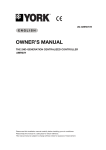
Figure #1 shows the screen that the LabVIEW sample produces,
that is, virtual thermometers of all the eight channels, and a graph
of one of these channels (user selectable).
Here is an explanation of the LabVIEW sample & how it might be used:
The included sample LabVIEW ‘vi’ file enables users of LabVIEW to
quickly start acquiring data from the TCIC.
If a LabVIEW application is to be used simply to acquire data from the
TCIC, then it is recommended that the TCIC-Monitor is used to configure
the TCIC prior to communication with LabVIEW. For the LabVIEW
sample, the TCIC-Monitor should be used to setup the TCIC for 8
thermocouple (i.e., not mV) inputs.
The LabVIEW sample is setup for serial communication with the TCIC.
This can be either via USB (using Virtual COM Port drivers supplied with
the TCIC) or through direct RS232 or RS485 COM ports.
If USB communication is being used, then the TCIC USB drivers must be
installed prior to using LabVIEW; also the TCIC must be attached and
powered before LabVIEW is started, otherwise LabVIEW will not see the
USB virtual COM port.
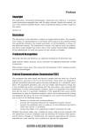
The sample ‘vi’ requires that the correct COM port is selected prior to
running the application: use NI’s Measurement and Automation Explorer
(often abbreviated to “MAX”) to search for attached devices. This utility
is available when the LabVIEW system is present. Figure #2 is a
screenshot of MAX, where the TCIC appears as COM7, as it does on the
LabVIEW sample screen also (refer to the top of figure #1).
The LabVIEW sample is provided ‘as is’ and is only intended as a starting
point to developing TCIC LabVIEW applications. The other parts of the
User’s Manual (particularly section 4) provide a more comprehensive
guide to the features and command set of the TCIC that may be
accessed by a user’s application.
39
TCIC User’s Manual
Figure #1 – output screen of the LabVIEW sample
Figure #2 – LabVIEW’s MAX (Measurement and Automation Explorer)
40