1
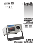
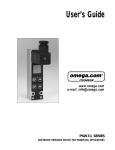
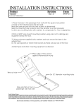
CONTENTS
PAGE
1. INTRODUCTION
1
Full description of the DP97
Front Panel information at a glance
2. INSTALLATION
3
Supply Connection
Input connections – Sensors
3. OPERATION
i)
ii)
iii)
iv)
v)
4
To read sensor temperature directly
To read differential temperature
Matching DP97 to calibrated sensors
Error indications
¾ wire recognition
4. INSTRUMENT RE-CALIBRATION
6
5. ANALOGUE (RE-TRANSMISSION) OUTPUT
8
Connection and Operation
6. RS232 COMMUNICATIONS
9
Connection and Operation
Using RS232 interface for digital probe matching (corrections)
7. USE OF “CORRECTIONS PC SOFTWARE”
12
Information in this publication may be subject to change; the DP97 is a
microprocessor based, software driven instrument and may therefore be subject
to software and hardware changes in line with our policy of continuous product
development.
1. INTRODUCTION
A high precision portable thermometer for metrology and other exacting laboratory
applications, the DP97 is a proven instrument used world wide as a laboratory and site
standard in pharmaceuticals, medical, food, environmental testing, R & D, and general
industrial applications.
It is particularly suitable as the reference standard for
temperature calibration baths.
The DP97 Digital Thermometer utilises highly advanced microprocessor circuit design to
achieve exceptional measuring accuracy, linearisation conformity and stability in a
versatile but easy to use configuration.
Based on a high resolution 20 Bit Analogue to Digital Converter, all measurement
computations are performed digitally without drift. The 5 digit LED display provides a
readout to 0.01°C over the entire –199.99 to +849.99°C range; alternatively °F, Kelvin or
Ohms values can be displayed up to 999.99 units.
Single or dual Pt100 3 or 4 wire sensors are accepted; the DP97 will automatically
recognise and select 3 or 4 wire mode. Display of input A, B OR a-B (differential) can
be selected; a differential “zero function” allows sensor accuracy differences to be
eliminated for accurate differential readings.
An RS232 interface (remote control and measure) is fitted as standard and isolation is
incorporated. An analogue (retransmission) output is also fitted as standard; the 1V dc
output is programmable between lower and upper set limits.
Calibrated sensors can have their calibration points programmed into the DP97 via a
personal computer using Labfacility software. The instrument then digitally self
calibrates to the probe(s) providing corrected temperature readout to give optimum
system accuracy.
The non-volatile memory ensures permanent retention of the values until the user
wishes to re-programme using the software, preventing unauthorised personnel from
changing the values.
Primary power is provided by an internal, re-chargeable sealed lead-acid battery, which
provides in excess of 12 hours operation from a full charge. A mains adapter is
provided for re-charging and for operation directly from the mains.
A range of precision stainless steel sheath Pt100 probes is available for the DP97.
Page 1
Front Panel Information at a Glance: when you switch on
To obtain a reading from a temperature sensor, select channel A or B (1) and select the
required units (2).
The appropriate indicator LED indicates the selected channel and units. For version 2.1,
the A and/or B LED indicators, according to the channel selected, cycle between a
steady on state and a brief off state (occulting) when corrections are stored and applied
to measurements (not applicable to version 1.4). To read differential temperatures from
two sensors, select channel A-B (1) and select the required units (2).
To set an A-B reading of zero to “null out” probe differences, press NULL (3).
Error Indications:
The DP97 has several modes of error indication according to internal or external
problems. Refer to section 3,4 for details.
Page 2
2. INSTALLATION
Back Panel
General
a)
b)
The standard version is for bench-top use. Retractable legs can be
extended to provide a convenient viewing angle.
The optional version permits the installation of the DP97 into a
suitable panel cut out.
Supply Connection
Primary power is provided by the internal, rechargeable sealed lead-acid battery which
provides up to 12 hours operation from a full charge. The external supply adapter for
recharging and also allows operation directly from a 220/240V 50/60Hz supply (or 110V
50/60Hz to special order). The output lead with its fitted connector is connected to the
appropriate rear panel mating connector.
Internal battery power can provide operation for up to 12 hours from full charge. Low
battery charge state is indicated by “bAtt” on the display.
Input Connections – Sensors
Platinum Resistance Thermometer(s) (Pt100) must be fitted with a high quality D-plug
and connected to INPUT A and/or INPUT B as required. A 3 OR 4 wire configuration
can be used but they are connected differently as shown. The DP97 will automatically
sense which configuration is employed.
Special care must be taken when connecting 3 wire resistance thermometer
terminations to the connector pins. A good crimp must be achieved to avoid Ohmic
contacts, which would result in reading errors. Only use good quality connectors with
gold contact mate rial; the OMEGA D type is recommended.
Page 3
3. OPERATION
Ensure that the instrument is connected to a suitable supply or has charged batteries
and that the required input connections are made.
Switch “on” using the rear mounted rocker switch.
The display will show “Pr 2.1” or “Pr 1.4” the programme designation. There is a short
delay while internal checks are carried out, then the input A value will be displayed.
i)
To read sensor temperature directly
a)
PRT input A is automatically selected at switch-on. Brief repeated
key presses will step through the various functions or holding
the key depressed will auto repeat (scroll through); this applies
to the other functions as well.
Note: If for any selected channel, the sensor is either not connected or has a faulty
connection (including sensor open-circuit), the LED display will show:- “Err 3”
Press any button to resume normal operation (either select another channel or rectify
any fault and continue intended use).
b)
c)
ii)
Press CHANNEL to select inputs A,B or A-B (differential).
Press UNITS to display the desired units °C, °F, K, or Ω
To read Differential Temperature
The difference in temperature between two PRT sensors can be obtained
by displaying A-B.
Ensure that the necessary sensors are connected to both A and B inputs
as required.
Press CHANNEL to select A-B
Press UNITS to display the desired units
The value now displayed is the difference between the input A and input B
(A-B) for the sensor type indicated.
Null Feature
For calorimetry and other applications to optimise the precision of differential
measurements, probe tolerances can be nulled by pressing the NULL key when in A-B
mode. This gives an A-B reading of zero when pressed regardless of any real difference
value.
Page 4
iii)
Matching DP97 to Calibrated Sensors
It is possible to automatically match the DP97 to a Pt100 sensor with up to
10 dedicated calibration values. Such values, published in an associated
certificate indicate true Ω versus °C values corresponding to accurately
known reference temperatures. Up to 10 sets of values per sensor can be
fed into the instrument via the RS232 interface using the associated
software supplied with each version 2.1 instrument as standard.
By matching the instrument to a probe on this basis, “corrected”
temperature readings are obtained directly without the need for crossreferencing to temperature/resistance tables or to the calibration
certificate. This is particularly helpful when taking differential (A-B)
readings.
Refer to sections 6 and 7 for details.
iv)
Error Indications
The DP97 has several modes of error indication according to internal or
external problems as follows:
Display
Err 1
Err 2
Err 3
Err 4
BAtt
Or
Ur
Cause
Calibration lost (very unlikely)
Software fault
Broken probe connection
RS 232 command error
“Low” battery
Over-range input
Under-range input
Only Err 1 / Err 2 would require returning the instrument to our factory.
Note:
During normal operation, if a selected probe is disconnected from the
instrument the display will indicate Err 3 (broken probe indication). If the same probe is
re-connected, Err 3 will remain on the display until any key is pressed.
v)
¾ Wire Recognition
DP97 requires a minimum of 80mΩ lead resistance (eg. 1 metre of 7
stranded 0.2 mm² wire) to recognise a 4 wire probe. Otherwise the
instrument will default (perhaps incorrectly) to 3 wire mode.
If a simulator is used to apply resistance values to check or calibrate the
DP97 ensure that at least 80mΩ of lead resistance exists between the
simulator and the D plug.
Page 5
If using a shorter leadout from the probe or thicker gauge cable, please
ensure that the DP97 is in the correct wire recognition mode. This can be
checked by pressing the SPAN s button ONCE.
Two numbers will be displayed e.g. 3-4. The first digit being the X
parameter (e.g.3) and the second digit being the Y parameter (e.g.4).
These displayed numbers will only be displayed momentarily.
Caution, pressing the SPAN s button more than once or holding it down
continuously will alter the X-Y setting.
X Parameter
This is a configurable parameter. If the probe configuration is 4 wire but
has a lead resistance of less than 80mΩ per leg, he instrument may
recognise it as a 3 wire probe (showing 3-3); the SPAN s may be used to
force the instrument into a 4 wire measurement mode by pressing SPAN
s until X = 4. To verify, allow the DP97 to ead the currently selected
channel and press SPAN s once; the display will now show 4-4.
X=3
3 or 4 wire mode is allowable on either channel A or B i.e. A4, B3 or A3,
B4 or A3, B3 or A4; B4 (if both probes are 4 wire). I.e. 3 or 4 wire auto
Selected.
X=4
4 wire mode is mandatory o n both channels A & B I.E. A4, B4.
Y Parameter
The Y parameter gives the actual measuring mode of the currently
selected channel (except differential).
Y=3
3 wire measuring
Y=4
4 wire measuring
Differential Mode
In A-B mode the SPAN s figure is not to be relied upon because the values
displayed will be for the last channel which has been read by the instrument and
this could be A OR B.
In order to verify status of each channel, select the channels A and B individually.
4. INSTRUMENT RE-CALIBRATION
Re-calibration of the DP97 is unlikely to be required routinely unless specified by user
regulations. If this is performed by someone other than the supplier, guarantee of
specification compliance may be invalid.
Page 6
The calibration kit option (two precision resistors) is required to perform re-calibration.
No additional instruments are required since the DP97 self-calibrates as follows:
Caution: Do not proceed unless specified resistors are available. Failure to do so
may invalidate the warranty.
a)
With the supply disconnected, remove the instrument
case cover by removing the two screws on the rear
panel and sliding the cover off the rear of the
instrument.
b)
Insert the jumper JP1 (shorting connector) – this
places the DP97 into self-calibrating mode.
Connect the supply and switch on*. Calibration is
simply a matter of connecting the precision resistors in
sequence. The necessary value of the resistor, together
with the input to which it has to be applied is indicated
on the display. The steps are as follows:
*At this point, the existing calibration has now been over-written by default
values. The procedure should therefore now be completed.
i)
Connect 100 Ohm calibration resistor to PRT INPUT a.
ii)
Press “SPAN s ” and display will show a value close to 100 Ohms. If the
value shown is wrong by more than 1.00 Ohms, a fault exists and the
Instrument must be returned for rectification.
iii)
Press “SPAN s ” again and the instrument will compute the average value
of 16 readings of the resistor value.
iv)
When the display reads “A = 250”, connect the 250 Ohm calibration
resistor to input A.
v)
Press “SPAN s ” and display will show a value close to 250 Ohms. If the
value shown is wrong by more than 1.00 Ohms, a fault exists and the
instrument must be returned for rectification.
vi)
Press “SPAN s ” again and the instrument will compute the average value
of 16 readings of the resistor value.
vii)
Repeat steps (I) to (vi) for input B.
The DP97 then returns to a normal power-up state, PRT A, degrees C.
Page 7
Switch off the Instrument
1) Remove the jumper lead JP1. This is VITAL.
Should the instrument be switched on with JP1
In position, the calibration is lost.
2) Replace the instrument cover.
The instrument is now ready for normal use. The central processor is software
driven and no other adjustments or modifications should be attempted. If it is
necessary for the supplier to re-calibrate an instrument in consequences of
unauthorised persons so doing, a charge may be made accordingly
5. ANALOGUE (RE-TRRANSMISSION) OUTPUT
This output varies linearly between 0 and 1 volt dc. The output will be 0V whenever the
reading of the instrument is at or below the zero parameter as set by front panel button
pushes or RS232 commands. The output will be at 1 V whenever the reading is at the
span parameter as set by the user. Any reading between zero and span will result in an
Analogue output signal proportional to the position of the reading with respect o the
defined zero and span values. To set-up the output values:
1) Zero:
Press “SHIFT” and “ZERO s” to raise the value (in current units) at which
a zero output will occur.
Press “SHIFT” and “ZERO t ” to reduce the value in a similar way.
2) Span:
Press “SHIFT” and “SPAN s ” to raise the value (in current units)
at which a SPAN (1V) output will occur.
Press “SHIFT” and “SPAN t ” to reduce the value in a similar way.
The size of the increment is 0.1 Ohm. This is necessary so as to eliminate the
requirements of working from degrees in temperature (K, C or F) back to Ohms. If
setting up in degrees, some odd looking numbers may occur on the display.
The output falls to 0V in the event of the selected span value being exceeded; this is
done to indicate such a condition.
Page 8
6. RS232 COMMUNICATIONS
General
Remote control will be seized by sending an RS232 character, and relinquished by
sending the LOCAL command. While in remote control the front panel buttons will be
locked out (inoperative) and the right hand decimal point will indicate remote operation
(local lock-out). RS232 parameters will be a fixed baud ate and word length. 9600
Baud, 8 Data, No parity, 1 stop bit.
Remote control of calibration has not been included. (Refer to section 4).
Protocol:
Command strings are limited to a single statement action will occur on receipt of
The “end of line” character. All actions will return a status character followed by
Data if appropriate. The status will be “•” for a successful transaction; Other
values indicate syntax error, broken probe etc.
All commands may be abbreviated to their first two letters eg. UNITS OHMS
becomes UN OH. Input delimiters will be spaces or commas.
Page 9
Command set:
Display parameters:
UNITS
UNITS
UNITS
UNITS
INPUT
INPUT
INPUT
OHMS
C
K
F
A
B
A-B
Analogue parameters:
SPAN
Value in Ohms
ZERO Value in Ohms
Measurement:
MEASURE
Return to Local:
LOCAL
Output Protocol
Replies will depend on the command implemented, and will be numeric or – with
commas and spaces as delimiters. All replies will be terminated by CR and LF. The
first number will be an error code.
0
1
2
3
4
6
7
No error
Calibration lost (EEPROM corruption)
Broken probe
Syntax error
There will be no fur ther numbers if:
a)
b)
There is an error
The primary command was UNITS, INPUT or LOCAL
Further output will be provided in the case of MEASURE, DUMP (DIAGNOSE).
1.
MEASURE
Eg. If output is 0, 2351.7
First number
Second number
- error code
- value in units set by previous commands
Page 10
For digital probe matching within the instrument (version 2.1 only) additional
commands are used as follows:
CORRECTIONS
A
B
AB
OFF
(turns OFF B corrections)
Turns A on
(turns OFF A corrections)
Turns B on
(turns ON BOTH A & B corrections)
(turns OFF BOTH A & B corrections)
Whatever is set by this command is retained during power-down.
LA
LB
CA
CB
Query
XX*
ENABLE*
IC
Lists Ch A corrections
Lists Ch B corrections
Enter Ch A corrections
Enter Ch B corrections
Says “Not enabled”, “A”, “B”, “AB”
Disables corrections
Enables corrections
Initialise corrections (i.e.Erase) – useful after installing software
*For these commands to be actioned the SPANs
s key must be pressed as the
command is typed.
Corrections entered as Follows
Type
CA <CR>
2 <CR>
100,000 <CR>
0.000 <CR>
Y <CR>
138.510 <GR>
100.000 <CR>
Y <CR>
TM Sends
How Many Points
Entry=/0 Ohms
Deg C?
0100.0000 Ohms 0000.0000 Deg C ok?
Entry=/1 Ohms
Deg C?
0138.5100 Ohms 0100.0000 Deg C ok?
Done
This would repeat for more points.
Pressing N at the ok? Prompt will allow re-entry of the point.
Once entered, type LA OR LB TO SEE/CONFIRM CONTENTS.
Rules of entry.
1) Ohmic values must always increment from point to point
2) All values must be entered to THREE decimal places i.e:- .001,0.001,10.001 are all?
ok.
Page 11
Note: Use of the DP97 “CORRECTIONS PC SOFTWARE” supplied with the instrument
facilitate the correction procedure by means of a much simplified, user-friendly approach
described below.
7. USE OF CORRECTIONS PC SOFTWARE for Digital Probe Matching
a) Instrument set-up and software loading
PC Requirements: Any PC running in MS-DOS and having a 3½ ” disk drive,
mouse and mouse drive r installed, (the software can be used without a mouse; use
up/down arrows and/or ALT key with the highlighted letter in each function box). A
printer will allow hard copies to be taken.
Using DP97 software & RS232 interface lead.
i)
Connect the RS232 interface lead to the DP97 and to the PC according to the
Pin configuration shown in section 6).
ii)
Switch on the instrument and PC
iii)
At the C:\> prompt, select the drive (if this is the correct drive for the PC in
use) i.e. C:\a: “ENTER”
At the a:\> prompt type “TM-C” and “ENTER”. If using comms port 2, type
“TM-C/2”.
After the introduction screen, the MAIN MENU will appear (refer to MAIN
MENU diagram).
Note 1: These instructions are included in the software as the “text file” and can be
Viewed or printed out as required.
Note 2:
Prior to despatch the DP97 and PC software should be “enabled” for normal
operation. In the unlikely event of a communications problem between the
two items, please perfo rm the following procedure: With all set-up actions
completed the Main Menu on the PC screen, press the SPAN s key on
the DP97 whilst simultaneously clicking on the enable button on the Main
Menu. To check, click the Query button and the status box should confirm
enabled. Normal operation can now be carried out.
Note 3:
To prevent corrections being programmed into the DP97 click on disable
Button. See Note 2 to re-enable.
Page 12
Page 13
Page 14
b) Using the software
From MAIN MENU:To input calibration values into the DP97 (up to 10 may be used per channel):
º Click EDIT to obtain EDIT corrections menu.
º Enter values against #01 through #10 but note that
i)
ii)
iii)
º
º
º
º
All 10 need not be entered
When returning to main menu the Ù values are sorted into ascending order.
If the corresponding °C values are not in ascending order, the status box
will show Error.
All values must be entered with up to three decimal places e.g. 0.001,
10.001 etc. Both °C and Ù values must be entered.
Click return to Main Menu
From Main Menu, click FILES to obtain Load/Save/Print Menu
Click SPECIFY
Key file name into ‘CURRENT SELECTION’ File names end with .COR eg.
EXPI.COR. If .COR is not keyed in, it will be added automatically when ENTER
is pressed or OK clicked.
Note: File name should be cross referred to probe serial number.
º Click SAVE to save file
º Click LOAD to load data
º Click RETURN TO MAIN MENU and note loaded values are shown under
“Calibration Points”
º Click CHANNEL A <-> B
º Click SEND to transmit correction values to DP97
º Click CORRECT A, B OR A + B to switch on corrections
Note: Red dot in lower right hand corner of DP97 display window lights during “comms”
activity.
º Observe Channel A/B status LED on DP97 occults to indicate corrections stored
Within defined range. If this does not occult, probe reading does not lie within
corrections range and corrections are not used.
Page 15
Stored values can be viewed at any time as follows:
º From Main Menu, click CHANNEL to select channels A OR B
º Click READ
Stored values can be changed at any time by repeating input procedure. Stored
Values can be cleared from the DP97 at any time as follows:
º From Main Menu, click CHANNEL A <-> B
º Click DISABLE
º Click PRINT in load/save/print menu to print out corrections. To exit programme
and return to DOS, click EXIT on Main Menu.
Note: Although the DP97 stores only one set of corrections for each channel, the
number saved in the software is limited only by available diskette space. Data for many
probes can thus be stored.
When using corrections the DP97 channel annunciation lights (A or B) will occult at 4
second intervals according to the channel selected. In A-B mode channel A and/or B
annunciation lights occult at 8 second intervals.
It is important to note that the DP97 will revert to its standard resistance versus
temperature values for Pt100 sensors and the channel annunciation light will illuminate
normally, ie.the instrument interpolates only and will not extrapolate to extend
corrections outside the range entered.
When calibrating probes alone, prior to programming corrections into the DP97, we
recommend calibrating at a point slightly higher and a point slightly lower (e.g. by 5°C)
than the maximum and minimum temperatures expected for the probe in use. This
ensures corrections are always applied during normal operation. We recommend a
minimum of three correction values are programmed. The DP97 corrects only in
temperature (°C, °F, K). The Ohms value is not affected. Therefore, when measuring in
Ohms in corrected mode channel annunciation lights will not occult.
SPECIFICATIONS
All values are valid for a nominal 110v/240v 50Hz supply and 20°C ambient temperature
(±2°C).
Page 16
General
Range/Sensor type
Pt100 to IEC 751 (ITS 90 refers). –199.99 to 849.99°C.Ro =
100Ω. Two input channels, each 3 or 4 wire connection with
automatic recognition (with manual overrride).
Overall Instrument
Accuracy (4 wire)
±0.02°C ± 1 digit for range -200°C to +500°C.
±0.005% reading ± 1 digit for range 500°C to 850°C.
Overall System
Better than ±0.04°C with TM-l250 precision probe accuracy
(4 wire) from -50°C to +250°C with 5 point NAMAS
calibration.
Linearisation
Conformity
±0.01°C.
Stability
(vs ambient
temperature)
0.0025°C/°C ambient change.
Warm-up Time
Negligible under normal ambient conditions. Allow 5 to 10
minutes for full stability unless stored at low temperature,
then allow 30 minutes minimum.
Pt100 Sensor Current
0.5mA nominal.
Display Resolution
0.01°C, K, °F, Ω.
Measurement Units
°C, °F, K, Ω (user selectable).
Measurement Modes
Input A or B or A-B (differential). Null facility in A-B mode.
Custom Calibration
(via PC software)
Null Function
Sensor Lead
Resistance
Up to 10 calibration values can be allocated to (via PC
software) channels A and B. Values are retained in nonvolatile memory until replaced by user.
Corrects differential temperature readout between the two
Sensors to zero.
25Ω each lead maximum.
Page 17
Supply
Internal rechargeable batteries. Mains 110/240V 50/60Hz,
adapter included. Battery charge life up to 12 hours with full
charge dependent on pattern of usage.
Charger requirement 10 – 11.5V d.c. 1A.
Power Consumption
10W nominal. Max 20W when battery is charging.
Series Mode Rejection
60dB @ 50Hz (50mV rms applied).
Common Mode
Rejection
Ambient Temperature
Range
30V rms applied between input and earth produces no
measurable effect.
0-50°C non-condensing. Ensure stable temperature range
for best accuracy. Allow adequate warm-up time if moved
from region of low ambient temperature prior to use.
EMC Compliance
Meets EMC regulations. RFI to BS EN50081-1, 1992 and
immunity to BS.EN 50082-1, 1992.
CE Compliance
CE marked and compliant to current regulations.
Display
14mm LED, 5 DIGIT, 999.99 range.
Front Panel Controls
5 x membrane keys for user functions.
Input Connections
2 x Pt100.via “D” connectors
Mechanical
Mechanical/Case
Metal bench-top. Optional panel mounting kit.
Dimensions
145 x 66 x 240mm deep.
Weight
1.5Kg approximately.
Page 18
Communications
RS232 (standard)
PC Software
(standard)
Analogue Output
(standard)
Remote control and measure, Isolated, 9600 Baud, 8 data,
no parity, 1 stop bit.
PC software running in MS DOS allows programming
(standard) of custom calibration and preview of set values
from a PC. Also provides a print facility and storage of sets
of correction values.
Analogue 0 to 1 Volt d.c. between programmable (standard)
lower case and upper set limits representing channel A, B
or A-B. Accuracy 0.5% of reading. Non-isolated.
Page 19
WARRANTY/DISCLAIMER
OMEGA ENGINEERING, INC.
warrants this unit to be free of defects in materials and workmanship for a
period of 13 months from date of purchase. OMEGA’s WARRANTY adds an additional one (1) month grace period
to the normal one (1) year product warranty to cover handling and shipping time. This ensures that OMEGA’s
customers receive maximum coverage on each product.
If the unit malfunctions, it must be returned to the factory for evaluation. OMEGA’s Customer Service Department will
issue an Authorised Return (AR) number immediately upon phone or written request. Upon examination By OMEGA,
if the unit is found to be defective, it will be repaired or replaced at no charge. OMEGA’s WARRANTY does not apply
to defects resulting from any action of the purchaser, including but not limited to mishandling, improper interfacing,
operation outside of design limits, improper repair, or unauthorised modification. This WARRANTY is VOID if the
units shows evidence of having been tampered with or shows evidence of having been damaged as a result of
excessive corrosion; or current, heat, moisture or vibration; improper specification; misapplication; misuse or other
operating conditions outside of OMEGA’s control. Components, which wear, are not warranted, including but not
limited to contact points, fuses, and triacs.
OMEGA is pleased to offer suggestions on the use of its various products. However, OMEGA neither
assumes responsibility for any omissions or errors nor assumes liability for any damages that result from the
us of its products in accordance with information supplied by OMEGA, either verbal or written. OMEGA
warrants only that the parts manufactured by it will be as specified and free of defects. OMEGA MAKES NO
THER WARRANTIES OR REPRESENTATIONS OF ANY KIND WHATSOEVER, EXPRESS OR IMPLIED, EXCEPT
THAT OF TITLE, AND ALL IMPLIED WARRANTIES INCLUDING ANY WARRANTY OR MERCHANTABILITY AND
FITNESS FOR A PARTICULAR PURPOSE ARE HEREBY DISCLAIMED. LIMITATION OF LIABILITY: The
remedies of purchaser set forth herein are exclusive, and the total liability of OMEGA with respect to this
order, whether based on contract, warranty, negligence, indemnification, strict liability or otherwise, shall not
exceed the purchase price of the component upon which liability is based. In no event shall OMEGA be liable
for consequential, incidental or special damages.
CONDITIONS: Equipment sold by OMEGA is not intended to be used, nor shall it be used: (1) as a “Basic
Com ponent” under 10 CFR 21 (NCR), used in or with any nuclear installation or activity; or (2) in medical applications
or used on humans. Should any Product(s) be used in or with any nuclear installation or activity, medical application,
used on humans, or misused in any way, OMEGA assumes no responsibility as set forth in our basic
WARRANTY/DISCLAIMER language, and, additionally, purchaser will indemnify OMEGA and hold OMEGA harmless
from any liability or damage whatsoever arising out of the use of the Product(s) in such a manner.
RETURN REQUEST/INQUIRIES
Direct all warranty and repair requests/inquiries to the OMEGA Customer Service Department. BEFORE
RETURNING ANY PRODUCT(S) TO OMEGA, PURCHASER MUST OBTAIN AN AUTHORISED RETURN (AR)
NUMBER FROM OMEGA’S CUSTOMER SERVICE DEPARTMENT (IN ORDER TO AVOID PROCESSING
DELAYS). The assigned AR number should then be marked on the outside of the return package and on any
correspondence.
The purchaser is responsible for shipping charges, freight, insurance and proper packaging to prevent breakage in
transit.
FOR WARRANTY RETURNS, please have
the following information available BEFORE
contacting OMEGA:
FOR NON-WARRANTY REPAIRS, consult OMEGA
for current repair charges. Have the following
information available BEFORE contacting OMEGA:
1.
1.
2.
3.
Purchase Order number under which
the product was PURCHASED.
Model and serial number of the product
under warranty, and
Repair instructions and/or specific problems
relative to the product.
2.
3.
Purchase Order number to cover the COST of
the repair,
Model and serial number of the product, and
Repair instructions and/or Specific problems
relative to the product.
OMEGA’s policy is to make running changes, not model changes, whenever an improvement is possible. This affords
our customers the latest in technology and engineering.
OMEGA is a registered trademark of OMEGA ENGINEERING, INC.
© Copyright 2000 OMEGA ENGINEERING, INC. All rights reserved. This document may not be copies,
photocopied, reproduced, translated, or reduced to any electronic medium or machine-readable form, in whole or in
part, without the prior written consent of OMEGA ENGINEERING, INC.
Servicing North America:
USA:
ISO 9001 Certified
One Omega Drive, P.O. Box 4047
Stamford CT 06907-0047
TEL: (203) 359-1660
FAX: (203) 359-7700
e-mail: [email protected]
Canada:
976 Bergar
Laval (Quebec) H7L5A1
TEL: (514) 856-6928
e-mail: [email protected]
FAX: (514) 856-6886
For immediate technical or application assistance:
USA and Canada:
Sales Service: 1-800-826-6342 / 1-800-TC-OMEGA
Customer Service: 1-800-622-2378 / 1-800-622 BEST
Engineering Service: 1-800-872-9436 / 1-800-USA-WHEN
TELEX: 996404 EASYLINK: 62968934 CABLE: OMEGA
Mexico:
En Español: (001) 203-359-7803 e-mail:[email protected]
[email protected]
Servicing Europe:
Benelux:
Postbus 8034, 1180 LA Amstelveen, The Netherlands
TEL: +31 (0)20 3472121
FAX: +31 (0)20 6434643
Toll Free in Benelux: 0800 0993344
e-mail: [email protected]
Czech Republic:
Rudé armády 1868,733 01 Karviná 8
TEL: +420 (0)69 6311899
FAX:
Toll Free: 0800-1-66342
France:
9, rue Denis Papin, 78190 Trappes
TEL: +33 (0)130 621 400
Toll Free in France: 0800-4-06342
e-mail:[email protected]
+420 (0)69 6311114
FAX: +33 (0)130 699 120
Germany/
Austria:
Daimlerstrasse 26, D-75392 Deckenpfronn, Germany
TEL: +49 (0)7056 9398-0
FAX: +49 (0)7056 9398-29
Toll Free in Germany: 0800 639 7678
e-mail:[email protected]
United Kingdom:
ISO 9002 Certified
One Omega Drive, River Bend Technology Centre
Northbank, Irlam, Manchester
M44 5ex United Kingdom
TEL: +44 (0)161 777 6611
FAX: +44 (0)161 777 6622
Toll Free in United Kingdom:0800-488-488
e-mail:[email protected]
It is the policy of OMEGA to comply with all worldwide safety and EMC/EMI regulations that apply.
OMEGA is constantly pursuing certification of its products to the European New Approach Directives.
OMEGA will add the CE mark to every appropriate device upon certification.
The information contained in this document is believed to be correct, but OMEGA Engineering, Inc.
accepts no liability for any errors it contains, and reserves the right to alter specifications without notice.
WARNING: These products are not designed for use in, and should not be used for, patient-connected
applications.
Where Do I Find Everything I Need for
Process Measurement and Control?
OMEGA…Of Course!
Shop online at www.omega.com
TEMPERATURE
þ
þ
þ
þ
þ
Thermocouple, RTD 7 Thermistor Probes, Connectors, Panels & Assemblies
Wire: Thermocouple, RTD & Thermistor
Calibrators and Ice Point References
Recorders, Controllers & Process Monitors
Infrared Pyrometers
PRESSURE, STRAIN AND FORCE
þ
þ
þ
þ
Transducers & Strain Gauges
Load Cells & Pressure Gauges
Displacement Transducers
Instrumentation & Accessories
FLOW/LEVEL
þ
þ
þ
þ
Rotameters, Gas Mass, Flowmeters & Flow Computers
Air Velocity Indictors
Turbine/Paddlewheel Systems
Totalizers & Batch Controllers
pH/CONDUCTIVITY
þ
þ
þ
þ
pH Electrodes, Testers & Accessories
Benchtop/Laboratory Meters
Controllers, Calibrators, Simulators & Pumps
Industrial pH & Conductivity Equipment
DATA ACQUISITION
þ
þ
þ
þ
þ
Data Acquisition & Engineering Software
Communications-Based Acquisitions Systems
Plug-in Cards for Apple, IBM & Compatibles
Datalogging Systems
Recorders, Printers & Plotters
HEATERS
þ
þ
þ
þ
þ
Heating Cable
Cartridge & Strip Heaters
Immersion & Band Heaters
Flexible Heaters
Laboratory Heaters
ENVIRONMENTAL MONITORING & CONTROL
þ
þ
þ
þ
þ
þ
Metering & Control Instrumentation
Refractometers
Pumps & Tubing
Air, Soil & Water Monitors
Industrial Water & Wastewater Treatment
pH, Conductivity & Dissolved Oxygen Instruments