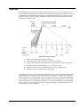
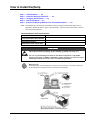
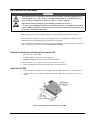
1
User’s Guide
Shop online at
omega.com
e-mail: [email protected]
For latest product manuals:
omegamanual.info
OMB-DAQTEMP Series
High Accuracy PCI Thermocouple / Multifunction Data Acquisition Systems
OMB-1108-0901 rev 1.2
OMEGAnet ® Online Service
omega.com
Internet e-mail
[email protected]
Servicing North America:
U.S.A.:
ISO 9001 Certified
Canada:
One Omega Drive, P.O. Box 4047
Stamford, CT 06907-0047
TEL: (203) 359-1660
e-mail: [email protected]
976 Bergar
Laval (Quebec) H7L 5A1, Canada
TEL: (514) 856-6928
e-mail: [email protected]
FAX: (203) 359-7700
FAX: (514) 856-6886
For immediate technical or application assistance:
U.S.A. and Canada: Sales Service: 1-800-826-6342 / 1-800-TC-OMEGA®
Customer Service: 1-800-622-2378 / 1-800-622-BEST®
Engineering Service: 1-800-872-9436 / 1-800-USA-WHEN®
Mexico:
En Español: (001) 203-359-7803
FAX: (001) 203-359-7807
e-mail: [email protected]
[email protected]
Servicing Europe:
Benelux:
Postbus 8034, 1180 LA Amstelveen, The Netherlands
TEL: +31 (0)20 3472121
FAX: +31 (0)20 6434643
Toll Free in Benelux: 0800 0993344
e-mail: [email protected]
Czech Republic:
Frystatska 184, 733 01 Karviná, Czech Republic
TEL: +420 (0)59 6311899
FAX: +420 (0)59 6311114
Toll Free: 0800-1-66342
e-mail: [email protected]
France:
11, rue Jacques Cartier, 78280 Guyancourt, France
TEL: +33 (0)1 61 37 2900
FAX: +33 (0)1 30 57 5427
Toll Free in France: 0800 466 342
e-mail: [email protected]
Germany/Austria: Daimlerstrasse 26, D-75392 Deckenpfronn, Germany
TEL: +49 (0)7056 9398-0
Toll Free in Germany: 0800 639 7678
e-mail: [email protected]
United Kingdom:
ISO 9002 Certified
FAX: +49 (0)7056 9398-29
One Omega Drive, River Bend Technology Centre
Northbank, Irlam, Manchester
M44 5BD United Kingdom
TEL: +44 (0)161 777 6611
FAX: +44 (0)161 777 6622
Toll Free in United Kingdom: 0800-488-488
e-mail: [email protected]
It is the policy of OMEGA Engineering, Inc. to comply with all worldwide safety and EMC/EMI
regulations that apply. OMEGA is constantly pursuing certification of its products to the European New
Approach Directives. OMEGA will add the CE mark to every appropriate device upon certification.
The information contained in this document is believed to be correct, but OMEGA accepts no liability for any
errors it contains, and reserves the right to alter specifications without notice.
WARNING: These products are not designed for use in, and should not be used for, human applications.
Warnings, Cautions, Notes, and Tips
Refer all service to qualified personnel. This symbol warns of possible personal injury or equipment damage under
noted conditions. Follow all safety standards of professional practice and the recommendations in this manual. Using
this equipment in ways other than described in this manual can present serious safety hazards or cause equipment
damage.
This warning symbol is used in this manual or on the equipment to warn of possible injury or death from electrical
shock under noted conditions.
This ESD caution symbol urges proper handling of equipment or components sensitive to damage from electrostatic
discharge. Proper handling guidelines include the use of grounded anti-static mats and wrist straps, ESD-protective
bags and cartons, and related procedures.
This symbol indicates the message is important, but is not of a Warning or Caution category. These notes can be of
great benefit to the user, and should be read.
In this manual, the book symbol always precedes the words “Reference Note.” This type of note identifies the location
of additional information that may prove helpful. References may be made to other chapters or other documentation.
Tips provide advice that may save time during a procedure, or help to clarify an issue. Tips may include additional
reference.
Specifications and Calibration
Specifications are subject to change without notice. Significant changes will be addressed in an addendum or revision to
the manual. As applicable, we calibrate our hardware to published specifications. Periodic hardware calibration is not
covered under the warranty and must be performed by qualified personnel as specified in this manual. Improper
calibration procedures may void the warranty.
iii
Your order was carefully inspected prior to shipment. When you receive your order, carefully
unpack all items from the shipping carton and check for physical signs of damage that may have
occurred during shipment. Promptly report any damage to the shipping agent and your sales
representative. Retain all shipping materials in case the unit needs returned to the factory.
CAUTION
Using this equipment in ways other than described in this manual can cause
personal injury or equipment damage. Before setting up and using your
equipment, you should read all documentation that covers your system.
Pay special attention to Warnings and Cautions.
Note:
During software installation, Adobe® PDF versions of user manuals will automatically
install onto your hard drive as a part of product support. The default location is in the
Programs group, which can be accessed from the Windows Desktop. Initial
navigation is as follows:
Start [Desktop “Start” pull-down menu]
⇒ Programs
⇒ Omega DaqX Software
You can also access the PDF documents directly from the data acquisition CD by using
the <View PDFs> button located on the opening screen.
Refer to the PDF documentation for details regarding both hardware and software.
A copy of the Adobe Acrobat Reader® is included on your CD. The Reader provides
a means of reading and printing the PDF documents. Note that hardcopy versions of
the manuals can be ordered from the factory.
iv
Manual Layout
Chapter 1 – Overview and Theory of Operation. Explains what DaqTemps are, the differences between
the four DaqTemp models, and discusses certain aspects of data acquisition in relation to DaqTemp,
as well as the theory of operation for each DaqTemp model.
Chapter 2 – How to Install DaqTemp. Instructs the user on how to (1) install software, (2) install the
DaqTemp PCI board, (3) configure the PCI board, (4) test the PCI board, and (5) connect the
DaqTemp module to its associated PCI board.
Chapter 3 – Making Signal Connections. This chapter uses illustrations to identify the screw-type
terminals that are associated with various signal types including, but not limited to, Digital I/O,
Analog I/O, and Thermocouples. The chapter includes a thermocouple standards color-reference
table for the following thermocouple types: J, K, T, E, N28, N14, S, R, and B. The chapter also
includes important notes pertaining to thermocouples.
Chapter 4 – Software for DaqTemp Applications. Provides a brief introduction to out-of-the-box and
icon-driven software that can be used with DaqTemp. The chapter includes reference notes to
associated pdf formatted documents which the user will need to refer to for detailed information.
Chapter 5 – CE Compliance. Pertains to CE standards and conditions that are relevant to DaqTemps.
The chapter includes CE Kit installation instructions.
Chapter 6 – Calibration. Discusses the use of the DaqCal application that is included as a part of
product support.
Chapter 7 – Specifications. Includes specifications for the four types of DaqTemps currently in
production. DaqTemp7, DaqTemp7A, DaqTemp14, and DaqTemp14A.
Glossary
Reference Note:
Page iv discusses additional documents that are of importance to DaqTemp Users.
DaqTemp Series User’s Manual
10-14-02
v
vi
10-14-02
DaqTemp Series User’s Manual
Table of Contents
1 – Overview and Theory of Operation
Features and General Information ……1-1
Scanning….1-5
Triggering …… 1-6
Theory of Operation …… 1-7
2 – How to Install DaqTemp
Step 1 – Install Software …… 2-2
Step 2 – Install the DaqTemp PCI Board …… 2-2
Step 3 – Configure the DaqTemp PCI Board …… 2-4
Step 4 – Test the DaqTemp PCI Board …… 2-5
Step 5 – Connect the DaqTemp Module to its PCI Board …… 2-6
3 – Making Signal Connections
4 – Software for DaqTemp Applications
5 – CE Compliance
Overview …… 5-1
CE Standards and Directives ……5-1
Safety Conditions ……5-2
Emissions/Immunity Conditions ……5-2
CE Cable Kit for DaqTemp …… 5-3
6 – Calibration
7 – Specifications
Glossary
DaqTemp Series User’s Manual
10-14-02
vii
viii
10-14-02
DaqTemp Series User’s Manual
Overview and Theory of Operation
1
Features and General Information …… 1-1
Scanning…… 1-5
Triggering …… 1-6
Theory of Operation …… 1-7
Features and General Information
DaqTemps are reliable, accurate, and compact data acquisition solutions that evolved from a primary focus on
thermocouple applications. There are presently four DaqTemp systems. Each includes the following hardware
and software.
DaqTemp Hardware
DaqTemp Data Acquisition Module
DaqTemp PCI plug-in board
CA-195 Cable, 3 feet long
DaqTemp Software
DaqView
DaqViewXL
eZ-PostView
Drivers for LabVIEW, DASYLab, and Windows
DaqTemp’s Three Hardware Components
(Module, Cable, and PCI Board)
Card for Digital & Analog I/O
T/C Terminal Block
Card for Digital & Analog I/O
P4
T/C Terminal Block
P4
DaqTemp14 and DaqTemp14A Modules,
Internal Layout*
DaqTemp7 and DaqTemp7A Modules,
Internal Layout*
TC
DaqTemp Features
Counter/
Voltage
Frequency
Timer/
Pulse
Analog
Digital
Inputs
Inputs
Inputs
Outputs
Outputs
I/O
DaqTemp7
7
7
4
2
0
24
DaqTemp7A
7
7
4
2
2
24
DaqTemp14
14
7
4
2
0
24
DaqTemp14A
14
7
4
2
4
24
*Note: The following pages include larger illustrations of the DaqTemp Internal Layouts.
DaqTemp User’s Manual
09-06-02
Overview & Theory of Operation
1-1
Thermocouple Channels (CH1 - CH7, CH9 - CH15)
Each DaqTemp features on-board cold junction compensation (CJC) for direct measurement of type J,
K, T, E, N28, N14, S, R, and B thermocouples. The following table provides the temperature range for
each of these thermocouple types.
T/C Type
Temperature
Range °C
Temperature
Range °F
J
-200 to
760
-328 to
1400
K
-200 to
1200
-328 to
2192
Thermocouple Temperature Ranges
T
E
N28
N14
-200 to
-270 to
-270 to
0 to
400
650
400
1300
-328 to
-454 to
-454 to
32 to
752
1202
752
2372
S
-50 to
1768
-58 to
3214
R
-50 to
1768
-58 to
3214
B
50 to
1780
122 to
3236
DaqTemps are known mainly for their input of thermocouple signals. Up to seven thermocouples [channels
1 through 7] can be connected to a thermocouple terminal block located within the DaqTemp7 and
DaqTemp7A modules. Both the DaqTemp7 and DaqTemp7A use channel 0 for CJC (cold-junction
compensation).
Thermocouple Channel Connections for
DaqTemp7 and DaqTemp7A
Thermocouple Channel Connections for
DaqTemp14 and DaqTemp14A
Up to fourteen thermocouples can be connected to a thermocouple terminal block located within the
DaqTemp14 and DaqTemp14A modules. Channels 1 through 7 are used for the first seven thermocouples
and channels 9 through 15 for the second set of seven. Both the DaqTemp14 and DaqTemp14A use two
channels for CJC (cold-junction compensation). The CJC is measured on channels 0 and 8.
The DaqTemp PCI board has 8 differential analog inputs. One of these inputs is used to measure the
thermocouple channels, leaving the other 7 for general-purpose analog input measurement. The thermocouple board has its own analog multiplexer that is driven by expansion channel address signals from the
PCI board. The multiplexer chooses one of 16 signals for measurement (14 thermocouple inputs and
2 CJC inputs.)
Note: Each DaqTemp thermocouple input channel can be configured for a fixed voltage gain of 100.
When in this mode, voltage can be measured in the range of ±100 mV.
1-2
Overview & Theory of Operation
09-06-02
DaqTemp User’s Manual
Differential Input Channels (1H / 1L - 7H / 7L)
Each DaqTemp model has seven differential input channels for measuring voltage. The voltage channels
are labeled from 1H / 1L to 7H / 7L, with the “H” and “L” representing channel high and channel low.
The seven channels are located on the Analog I/O portion of the card.
Each differential input channel also has a current shunt resistor that can be user-installed. The resistor will
convert a current to a voltage, the voltage will then be measured by the DaqTemp PCI board. This is a
handy way to measure 4-20mA current loops or make current-based measurements in general. The righthand figure shows how the resistors are connected to both the low-side and high-side of each differential
input. Note that R1 is matched to analog input 1, R2 to analog input 2, etc.
Differential Input Channels 1 and 2
with User-Installed Resistors
Analog I/O Section of DaqTemp
Digital and Analog I/O Card
Analog Outputs (DAC0, DAC1, DAC2, and DAC3)
The “A” model DaqTemps have Analog Output capability. DaqTemp7A has two digital-to-analog
converters. These are designated as DAC0 and DAC1. DaqTemp14A has four DACs designated as DAC0,
DAC1, DAC2, and DAC3. The DAC channel connections are represented in the above, left-hand figure.
Note that the same Digital and Analog I/O Terminal Block Card is used in all DaqTemp models, regardless
of the unit’s features. Because of this, the following should be realized:
• DAC2 and DAC3 do not apply to DaqTemp7A. However, the Digital and Analog I/O Terminal
Block Card includes connection labels for DAC2 and DAC3.
• Analog Outputs do not apply to DaqTemp7 or to DaqTemp14. However, the Digital and
Analog I/O Terminal Block Card includes connection labels for DAC0, DAC1, DAC2, and DAC3.
DaqTemp User’s Manual
09-06-02
Overview & Theory of Operation
1-3
24-Bit, General Purpose Digital I/O (Channels A0 - A7, B0 - B7, and C0 - C7)
All DaqTemps have 24-bit, general purpose, digital I/O that can be used to directly control and monitor
24 digital I/O lines. The 24-bit digital I/O is divided into three 8-bit ports, which are labeled: A0-A7,
B0-B7, and C0-C7. Each port can be programmed as an 8-bit group for either input or output.
Digital I/O Section of DaqTemp Digital and Analog I/O Card
Frequency/Counter Inputs
(CNT0, CNT1, CNT2, and CNT3)
Each DaqTemp has four frequency/counter inputs that can be used for counting pulses. A 16-bit counter,
capable of counting up to 65,536 TTL-level transitions, resides behind each counter input. These inputs are
labeled CNT0, CNT1, CNT2, and CNT3 on the Digital and Analog I/O Terminal Block Card, as indicated
in the preceding figure.
Each of the four counters is capable of accepting frequency inputs of up to 10 MHz. The counters can be
cascaded to 32-bits, allowing over four billion counts to be totalized. As with all other inputs, the counters
can be read asynchronously under program control, or synchronously as a part of an analog and digital scan
group.
16-Bit Timer Outputs
(TMR0 and TMR1)
Two 16-bit timer outputs are built into every DaqTemp. Each timer-output can generate square waves
within a programmable frequency range of 16 Hz to 1 MHz. These outputs are labeled TMR0 and TMR1
on the Digital and Analog I/O Terminal Block Card, as indicated in the preceding figure.
Pacer Clock I/O (A/ICLK and A/OCLK)
All DaqTemp models have two signals that can be used as inputs for externally clocking the acquisition and
analog output DACs. A TTL input can be applied to A/ICLK that will start a scan every time a rising edge
occurs on the applied TTL input. Likewise, a TTL input can be applied to A/OCLK that will update the
DAC outputs every time a rising edge occurs on the applied TTL input. The pacer clock connection points
are indicated in the preceding figure. When using the internal pacer clock generator, the A/ICLK and the
A/OCLK can each be programmed as an output.
Hardware Trigger Input (TTLTRG)
All DaqTemp models have a TTLTRG input that can be used to trigger the start of an acquisition. The
connection point is indicated in the preceding figure.
Power Output
(+5V, DGND)
All DaqTemp models have a power output connection on the Digital and Analog IO card. The power
supplied has a voltage of 5V (+/-10%) and is sourced from the computer where the DaqTemp PCI board is
installed. No more than 500mA should be sourced out of this connection. See the preceding figure for the
power output connection points.
1-4
Overview & Theory of Operation
09-06-02
DaqTemp User’s Manual
Scanning
Every DaqTemp has an on-board scan sequencer that permits the user to select any combination of up to
512 channel/range combinations. The sequencer scans all channels contained in the sequence at the rate of
5 µs/channel, thereby minimizing the time-skew from channel-to-channel. The user can also set the time
between scan groups, from 0 to 6 hours. In addition to scanning analog inputs, the sequencer can scan
digital inputs and counter inputs.
DaqTemp Scanning Example
(1)
Channels can be sampled dynamically by the sequencer.
(2)
Gain can be programmed, for each channel, dynamically by the sequencer.
(3)
Unipolar or Bipolar operation can be programmed, for each channel, dynamically by the sequencer.
(4)
Thermocouples can be of the following types: J, K, T, E, N28, N14, S, R, B
(5)
Counter Inputs [any of four] can be scanned along with the analog and digital inputs.
(6)
Digital Input Ports can be sampled along with Analog Inputs.
The DaqTemp PCI board’s 512-location scan sequencer allows you to select each channel and associated
input amplifier gain. All channels are scanned at 200 kHz (5 µs/channel). In addition, the digital and
frequency inputs can be scanned using the same scan sequencer employed for analog inputs, enabling the
time correlation of acquired digital data to acquired analog data. The PCI board permits each scan group,
which can contain up to 512 channel/gain combinations, to be repeated immediately or at programmable
intervals of up to 6 hours. Within each scan group, consecutive channels are measured at a fixed rate of
5 µs per channel, or 10 µs per channel
DaqTemp User’s Manual
09-06-02
Overview & Theory of Operation
1-5
Triggering
Triggering can be the most critical aspect of acquiring data. The DaqTemp PCI Board supports a full
complement of trigger modes to accommodate a wide variety of applications.
Hardware Analog Triggering. Many data acquisition products claim analog triggering, but rely on the
PC to take readings and make a decision, which leads to uncertain and potentially long latencies. The
DaqTemp PCI Board uses true analog triggering, whereby the trigger level programmed by the user, sets an
analog DAC, which is then compared in hardware to the analog input level on the selected channel. The
result is analog trigger latency that is guaranteed to be less than 5 µs, significantly shorter than most data
acquisition devices. Any analog channel can be selected as the trigger channel. The user can program both
the trigger level, as well as the edge (rising or falling).
Digital Triggering (P1). A separate digital trigger input line is provided, allowing TTL-level triggering,
again with latencies guaranteed to be less than 5 µs. Both the logic levels (1 or 0), as well as the edge (rising
or falling), can be programmed for the discrete digital trigger input. The digital trigger input is labeled
TTLTRG on the Digital and Analog I/O Board.
Digital Pattern Triggering (P2). The DaqTemp PCI Board also supports digital pattern triggering,
whereby the user can designate any of the digital input ports as the trigger port. The programmed digital
pattern, including the ability to mask or ignore specific bits, is then compared to the actual input until a
match is detected, after which the sequencer begins the scan sequence.
Counter Triggering. Triggering can also be programmed to occur when one of the counters reaches,
exceeds, or is within a programmed level. Any of the built-in counter/totalizer channels can be programmed
as a trigger source.
Software-Based Triggering. Software-based triggering differs from the modes described above because
the readings, analog, digital, or counter, are interrogated by the PC to detect the trigger event, not in the
hardware as described above. The advantage of this mode is to permit triggering based on more complex situations, such as on a specific temperature, which was derived from the acquisition of at least two analog
measurements, plus the calculation of the measured temperature using linearization algorithms.
Normally software-based triggering results in long latencies from the time that a trigger condition is
detected, until the actual capturing of data commences. However, the DaqTemp PCI Board circumvents this
undesirable phenomenon by use of pre-trigger data. Specifically, when software-based triggering is
employed, and the PC detects that a trigger condition has occurred, (which may be thousands of readings
later than the actual occurrence of the signal), the DaqTemp PCI Board driver automatically looks back to
the location in memory where the actual trigger-causing measurement occurred. The acquired data that is
presented to the user actually begins at the point where the trigger-causing measurement occurs. The latency
in this mode is equal to one scan cycle.
Pre- and Post-Triggering Modes. Six modes of pre- and post-triggering are supported, providing a wide
variety of options to accommodate any measurement requirement. When using pre-trigger, the user must use
software-based triggering to initiate an acquisition.
1-6
•
No pre-trigger, post-trigger stop event. This, the simplest of modes, acquires data upon receipt of the
trigger, and stops acquiring upon receipt of the stop-trigger event.
•
Fixed pre-trigger with post-trigger stop event. In this mode, the user specifies the number of pretrigger readings to be acquired, after which, acquisition continues until a stop-trigger event occurs.
•
No pre-trigger, infinite post-trigger. No pre-trigger data is acquired in this mode. Instead, data is
acquired beginning with the trigger event, and is terminated when the operator issues a command to
halt the acquisition.
•
Fixed pre-trigger with infinite post-trigger. The user specifies the amount of pre-trigger data to
acquire, after which the system continues to acquire data until the program issues a command to halt
acquisition.
Overview & Theory of Operation
09-06-02
DaqTemp User’s Manual
•
Variable pre-trigger with post trigger stop event (driver support only). Unlike the previous pretrigger modes, this mode does not have to satisfy the pre-trigger number of readings before
recognizing the trigger event. Thus the number of pre-trigger readings acquired is variable and
dependent on the time of the trigger event relative to the start. In this mode, data continues to be
acquired until the stop trigger event is detected.
•
Variable pre-trigger with infinite post trigger (driver support only). This is similar to the mode just
described, except that the acquisition is terminated upon receipt of a command from the program.
•
Stop Trigger. Any of the software trigger modes described above can be used to stop an acquisition.
Thus an acquisition can be programmed to begin on one event, such as a temperature level, and then
stopped on another, such as a digital pattern event.
Theory of Operation
As implied by the following matrix, the operational material does not apply globally to every DaqTemp
Series PCI board. For example, the PCI boards for DaqTemp7 and DaqTemp14 have no analog output.
I/O Comparison Matrix
I/O Comparison Matrix
for DaqTemp Series PCI Boards
DaqTemp
Thermocouple
Channels
PCI Board
Analog Input
Channels
Analog Output
Channels
Digital I/O
Channels
Counter/
Timers
T/C
DaqTemp7A
7
7
2
24
4 Counters
2 Timers
DaqTemp14A
14
7
4
24
4 Counters
2 Timers
DaqTemp7
7
7
0
24
4 Counters
2 Timers
DaqTemp14
14
7
0
24
4 Counters
2 Timers
Synchronous Input Operations
The DaqTemp Series devices allow synchronous scanning and acquisition of Analog Input, Digital Input
and Counter Input Data at up to 200 kHz aggregate scanning rates. The Analog Input data can be either
voltage input or thermocouple input channels. The Digital Input data can be any of the 8-bit ports,
designated as Port A (A0 through A7), Port B (B0 through B7), and Port C (C0 through C7).
DaqTemp User’s Manual
09-06-02
Overview & Theory of Operation
1-7
Analog Input Channels
The DaqTemp Series PCI Boards allow analog input configuration for the voltage input channels and the
thermocouple input channels.
Channel Selection and Mode Settings
The DaqTemp module accepts up to 7 differential inputs.
Channel Range and Polarity
Each of the seven differential voltage input channels may be programmed for either unipolar or bipolar
mode with gain settings of 1, 2, 4, 8, 16, 32 or 64.
Digital Input Channels
The DaqTemp Series PCI Boards allow either synchronous scanning of digital input channels or
asynchronous I/O operations for all configured digital channels.
Counter Input Channels
The DaqTemp Series PCI Boards allow synchronous scanning of the 4 16-bit counter input channels. The
four 16-bit counter channels can also be cascaded into two 32-bit counter channels. For either cascaded or
non-cascaded counter channels each channel can be configured for:
•
•
Pulse Counting Mode – specifies that each counter should be cleared upon being read and placed into
the input scan.
Totalize Counting Mode – specifies that each counter is to free-run and not be cleared during the input
acquisition.
Synchronous Input Acquisition Clocking
The DaqTemp Series PCI boards allow clocking of the synchronized inputs either by an internal,
programmable pacer clock or by external clocking. These products use a sequencer to implement a
multiplexing approach to gathering the input data. This means that with either internal or external clocking
the entire channel scan (including the sampling time for each channel) may not exceed the maximum
aggregate rate of 200kHz.
External clocking for acquisition is accomplished by applying a TTL clock input to the A/ICLK on the
Digital and Analog IO board. With external clocking, the DaqTemp PCI board will start a scan every
time there is a rising edge on the A/ICLK input. All channels [analog and digital] within the scan group are
still measured at the 5 us/channel [or 10 µs/channel] rate, the scan stored in the sequencer will be repeated
at the rate of the A/ICLK input.
Synchronous Output Operations
The DaqTemp7A and DaqTemp14A PCI Boards allow synchronous output of any 2 or 4 DACS,
respectively. All D/A channels available may have output streamed to them and clocked out synchronously.
DAC output channels can be updated at the rate of an internal DAC pacer clock that is fully programmable
and separate from the acquisition pacer clock.
External clocking for analog output is also available by applying a TTL clock input to the A/OCLK on the
Digital and Analog IO board. With external clocking, the DaqTemp PCI board will update the DAC(s)
every time there is a rising edge on the A/OCLK input. All DAC channels that are enabled will be updated
at the same time. Alternatively, the DACs can be updated at the acquisition rate (either internally or
externally via A/ICLK) so that an entire scan is measured every time a DAC update is done.
1-8
Overview & Theory of Operation
09-06-02
DaqTemp User’s Manual
Output Channel Configuration
Analog Output Channels
Each D/A channel can be configured for waveform output individually. If the D/A channel is not
configured for waveform output, it then is available for asynchronous output operations.
Synchronous Output Clocking
The DaqTemp Series PCI Boards allow clocking of the synchronized output by the acquisition clock
source, an internal, programmable pacer clock or by an external clock source. When the clock source
generates a new clock signal all outputs are updated concurrently. Regardless of the clock source, the clock
may not exceed the maximum update rate of 100kHz.
Synchronous Output Data Source
The DaqTemp Series PCI Boards allow the data source for synchronized output operations to be that of a
memory based buffer or a file located on a mass storage medium. With either type of output data source,
the output data for all the channels are contained in the buffer and/or file. The file path may be any file
located on the machine or network accessible file.
Asynchronous I/O Operations
The DaqTemp Series PCI boards allow asynchronous input of any counter or digital channel that is not
currently configured for synchronous acquisition. The PCI boards for DaqTemp7A and DaqTemp14A also
allow for asynchronous output to any D/A channels that are not currently configured for waveform output.
In addition, the timer outputs can be programmed at any time regardless of the current state of synchronous
or asynchronous operations on other channels.
Digital I/O Channels
[Local 8255 Channels]
The DaqTemp Series PCI Boards have an Intel 8255 core in the digital I/O logic on the P2 port of the
product. With the Intel 8255 there are three 8-bit wide ports available for I/O and one 8-bit wide port for
configuration purposes. The configuration port is used to configure the other three 8-bit ports for either
input or output operations.
Pulse Stream Output Using Timers
The boards allow the generation of output pulses based upon a programmable setting. These output timers
can be set at any time regardless of the state of any synchronous or asynchronous operations which are
currently taking place on other channels.
Analog Output Channels
The boards that have analog output capabilities have the ability to output analog data to any of the available
(up to four) D/A channels. Each D/A channel may be asynchronously updated by an application if the D/A
channel is not currently being used for waveform output operations.
Frequency/Counter Input Channels
The DaqTemp Series PCI boards have counter input capabilities and have the ability to read counter input
[if the counter channel is not configured for synchronous acquisition]. As in the case of synchronous
operations the 4 16-bit counter input channels can be used individually or cascaded into 2 32-bit counter
channels. For either cascaded or non-cascaded counter channels each channel can be configured for:
DaqTemp User’s Manual
•
Clear on Read Mode - specifies that each counter should be cleared (reset to 0) upon being read.
•
Continuous Totalize Mode – specifies that each counter is to free-run and not be cleared during
the read operation.
09-06-02
Overview & Theory of Operation
1-9
Operation Matrix
Operation
DaqTemp7A
DaqTemp14A
PCI Board
PCI Board
DaqTemp7 and
DaqTemp14
PCI Board
Synchronous Input
Analog Inputs
Counter Inputs
Digital Inputs
Yes
Yes
Yes
Yes
Yes
Yes
Yes
Yes
Yes
Yes(2)
Yes(4)
No (0)
Yes
Yes
Yes(2)
Yes
Yes
Yes(4)
Yes
Yes
No (0)
Synchronous Output
Analog D/A Waveform Output
Asynchronous IO
Digital I/O
Timer Output (Pulse Generation)
Analog Output
Block Diagram
DACs apply to DaqTemp7A and DaqTemp14A (see Note 1).
DaqTemp7 and DaqTemp14 have no DACs.
DaqTemp PCI Board Block Diagram
1-10
Overview & Theory of Operation
09-06-02
DaqTemp User’s Manual
Each DaqTemp makes use of one high-speed, multi-function, PCI plug-and-play data acquisition board. The PCI
board features a 16-bit, 200-kHz A/D converter (ADC), digital calibration, bus mastering DMA, 24 digital I/O lines,
four counters, and two timers. In addition, the DaqTemp7A has two16-bit 100 kHz D/A converters (DACs); and the
DaqTemp14A has four DACs.
DaqTemp modules provide access to all of the system’s input and output signals. A 100-pin connector on each
module connects to a mating connector on the associated PCI board. The connection is made via a CA-195, 100conductor ribbon cable.
Signal types applicable to the DaqTemps are:
• Analog Input: 7 differential analog inputs with 13 software programmable ranges
(±10 V to ±156 mV full scale).
• General purpose: 24 lines for Digital I/O.
• 4 Counter Inputs, 2 Timer Outputs
• 2 Analog Outputs for DaqTemp7A
• 4 Analog Outputs for DaqTemp14A
• 7 Thermocouple Inputs for DaqTemp7A and DaqTemp7
• 14 Thermocouple Inputs for DaqTemp14A and DaqTemp14
The PCI board’s scan sequencer lets you select up to 512 channel/range combinations. The sequencer scans all
channels of the scan at 5µs per channel, or 10 µs per channel.
Bus mastering allows analog and digital/counter input data, as well as analog and digital output data, to flow between
the PC and the DaqTemp without consuming CPU time.
DaqTemps support a full complement of trigger modes including:
• Hardware analog triggering – A user-programmed trigger level sets an analog DAC, which is
compared in hardware to the analog input level on the selected channel. Trigger latency is < 5 µs.
• Digital and pattern triggering – The boards have separate digital trigger input line, allowing TTL-level
triggering and latencies less than 5 µs. The trigger can be programmed for logic level or edge triggering.
In pattern triggering, any of the digital input ports acts as the trigger port. You can program the digital
pattern.
• Software-based triggering – The PC detects the trigger event from readings, either analog, digital, or
counter. Six pre- and post-triggering modes are supported.
Additional features:
• 24 TTL-level digital I/O lines. They are divided into three 8-bit ports.
• Four 16-bit counters. Each can accept frequency inputs up to 10 MHz.
The counters can be cascaded into two 32-bit counters.
• Two 16-bit timer outputs. Each can generate square waves from 16 Hz to 1 MHz.
• Configuration through software. The DaqTemp modules and PCI boards have no switches or
jumpers.
• Analog Outputs, DaqTemp7A and DaqTemp14A only. The 16-bit, 100-kHz analog output channels
have an output range of -10 V to +10 V. (These channels are separate from the D/As used to determine
analog trigger levels.) Using Bus Mastering DMA, each D/A can output a waveform. Bus Mastering
DMA also allows for digital pattern generation on the 16-bit high-speed digital I/O port.
DaqTemp User’s Manual
09-06-02
Overview & Theory of Operation
1-11
1-12
Overview & Theory of Operation
09-06-02
DaqTemp User’s Manual
How to Install DaqTemp
2
Step 1 – Install Software …… 2-2
Step 2 – Install the DaqTemp PCI Board …… 2-2
Step 3 – Configure the PCI Board ….. 2-4
Step 4 – Test the PCI Board ….. 2-5
Step 5 – Connect the DaqTemp Module to its associated PCI Board …… 2-6
Note: You should keep your DaqTemp serial numbers and your DaqView/2000 authorization code (if
applicable) with this document. Space is provided below. The PCI board serial number is located
on its 100-pin P4 connector.
Important Numbers for Future Reference
DaqTemp Module Serial Number
DaqTemp PCI Board Serial Number
PCI Bus-Slot Location
Authorization Code (if applicable)
CAUTION
Take ESD precautions (packaging, proper handling, grounded wrist strap, etc.)
Use care to avoid touching board surfaces and onboard components. Only handle
boards by their edges (or ORBs, if applicable). Ensure boards do not come into contact
with foreign elements such as oils, water, and industrial particulate.
Reference Note:
Each DaqTemp’s PCI board plugs into a PCI bus-slot on a host PC. If needed, consult your
PC documentation in regard to its PCI bus and the associated slots.
DaqTemp Installation, A Pictorial Overview
DaqTemp User’s Manual
10-14-02
How to Install DaqTemp
2-1
Step 1 – Install Software
IMPORTANT: Software must be installed before installing hardware.
1. Remove previous version Daq drivers, if present. You can do this through Microsoft’s Add/Remove
Programs feature.
2. Place the Data Acquisition CD into the CD-ROM drive. Wait for PC to auto-run the CD. This may take a
few moments, depending on your PC. If the CD does not auto-run, use the Desktop’s Start/Run/Browse
feature.
3. After the intro-screen appears, follow the screen prompts.
Upon completing the software installation, continue with step 2, Install the DaqTemp PCI Board.
Step 2 – Install the DaqTemp PCI Board
IMPORTANT: Software must be installed before installing hardware.
IMPORTANT: Bus Mastering DMA must be Enabled.
For a DaqTemp to operate properly, Bus Mastering DMA must be enabled. Prior to installation,
verify that your computer is capable of performing Bus Mastering DMA for the applicable PCI
bus-slot. Note that some computers have BIOS settings that enable [or disable] Bus Mastering
DMA. If your computer has this BIOS option, ensure that Bus Mastering DMA is Enabled on the
appropriate PCI slot. Refer to your PC’s owner manual for additional information regarding Bus
Mastering DMA.
CAUTION
Turn off power to, and UNPLUG the host PC prior to removing the PC’s cover and installing a
DaqTemp PCI board. Electric shock or damage to equipment can result even under low-voltage
conditions.
Take ESD precautions (packaging, proper handling, grounded wrist strap, etc.)
Use care to avoid touching board surfaces and onboard components. Only handle boards by their
edges (or ORBs, if applicable). Ensure boards do not come into contact with foreign elements such
as oils, water, and industrial particulate.
2-2
1.
Turn off power to, and UNPLUG the host PC and externally connected equipment.
2.
Remove the PC’s cover. Refer to your PC Owner’s Manual as needed.
3.
Choose an available PCI bus-slot.
4.
Carefully remove the DaqTemp PCI board from its anti-static protective bag. If you have not already
done so, write down the serial number of your board. Space has been provided on page 2-1 for
recording the serial number.
How to Install DaqTemp
10-14-02
DaqTemp User’s Manual
5.
On the PC’s rear panel, loosen and remove the screw for the blank adapter plate that corresponds with
the chosen PCI bus. See the following figure.
Removing a Blank Adapter Plate from
the Host Computer’s Rear Panel (Steps 5 and 6)
6.
Remove the adapter plate. Refer to your PC Owner’s Manual if needed.
7.
Align groove in the DaqTemp PCI board’s edge-connector with the ridge of the desired PCI slot, and
with the corresponding rear-panel slot on the PC. See following figure.
Installing a DaqTemp PCI Board (Steps 7, 8, and 9)
8.
Push the board firmly into the PCI slot. The board will snap into position.
9.
Secure the board by inserting the rear-panel adapter-plate screw.
10. Replace the computer’s side cover and plug in all cords and cables that were removed in step 1 of this
procedure.
11. Apply power to, and start up the PC.
Note: At this point some PCs may prompt you to insert an installation disk. While this is rare, if you do
receive such a prompt simply place the install CD-ROM into the disk drive and follow additional
screen prompts.
DaqTemp User’s Manual
10-14-02
How to Install DaqTemp
2-3
Step 3 – Configure the DaqTemp PCI Board
DaqTemp PCI boards have no jumpers or switches to set. Configuration is performed, in its entirety,
through software. Refer to the following figure and steps to complete the configuration.
1.
Run the Daq Configuration control panel applet. Navigation
from the desktop to the applet is as follows:
Start ⇒ Settings ⇒ Control Panel ⇒ Daq*Configuration
(double-click).
2.
Double-click on the Device Inventory’s DaqTemp icon. The
DaqTemp Properties tab will appear.
If the DaqTemp icon is not present, skip to the following
section, Using ‘Add Device.’
Configuring DaqTemp via the Properties Tab
2-4
3.
Enter a “Device Name” in the text box, or use the default “DaqTemp.” Device Name is for identifying
the DaqTemp board. However, the Device Name actually refers to the PCI slot and not to the board.
4.
Verify that the “Device Type” is a DaqTemp PCI board, for example, “DaqBoard/2000,” as indicated
in the above figure. Available device types can be viewed via the pull-down list (▼).
5.
Confirm that the DaqTemp text box shows a Bus #, Slot #, and Serial Number. If this text box is
empty, use its pull-down list (▼) and select the serial number that matches the one for your board.
In the above figure we see that the Bus number is 2, the Slot number is 9, and the Serial Number
(S/N) is 171972.
How to Install DaqTemp
10-21-02
DaqTemp User’s Manual
Using “Add Device”
This method is for users who have accessed the Daq
Configuration control panel applet, but have no
DaqTemp icon.
(A) After accessing the Daq Configuration control
panel applet, click on the Add Device button (see
figure, right). The Select Device Type window will
appear.
(B) Using the Device Type’s pull-down list, select the
applicable board. In the example at the right
DaqTemp7 is selected.
(C) Click the OK button. The DaqTemp Properties tab
will appear.
At this point, complete steps 3 through 5, above.
Using “Add Device”
Step 4 – Test the DaqTemp PCI Board
Use the following steps to test the DaqTemp. Note that these steps are continued from those listed under the
previous section, “Configure the DaqTemp PCI Board.”
1. Select the “Test Hardware” tab.
2. Click the “Resource Test” button.
3. After the test is complete, click “OK.”
System capability is now tested for the
DaqTemp PCI board.
Test results will be displayed on the screen.
At this point we are ready to connect the
DaqTemp module to the PCI board.
Test Hardware Tab
(Condensed Screen Image)
DaqTemp User’s Manual
10-14-02
How to Install DaqTemp
2-5
Step 5 – Connect the DaqTemp Module to its PCI Board
Connecting the DaqTemp Module to the PCI Board
CAUTION
Turn off power to and unplug the host PC prior to connecting the DaqTemp to
the computer. Failure to do so could possible result in equipment damage.
Prior to mating the CA-195 cable’s P4 connectors to the PCI board and the
DaqTemp, be sure to align the P4 orientation indicators (▲
▲) of the connectors
that are being mated.
Connect the DaqTemp module to its PC-based PCI board as follows.
1.
Turn off and unplug the PC.
2.
Ensure that the P4 connector alignment indicators (▲
▲) on cable CA-195 and the DaqTemp module are
in alignment, and make the connection of cable to DaqTemp module.
3.
Align the cable’s remaining P4 connector with the PCI board’s P4 connector, then make the
connection.
At this point you can connect the signal lines to the DaqTemp module’s terminal blocks.
Refer to chapter 3 for details.
2-6
How to Install DaqTemp
10-14-02
DaqTemp User’s Manual
Making Signal Connections
3
Connect the signal lines to the intended terminals on DaqTemp’s card-mounted terminal blocks for Digital
or Analog I/O, and/or to the chassis-mounted terminal blocks for thermocouple connections.
In regard to thermocouples …
•
DaqTemp7 and DaqTemp7A provide input connections for channels 1 through 7.
•
DaqTemp14 and DaqTemp14A provide input connections for channels 1 through 7 and
for channels 9 through 15.
Card with Terminal Blocks for
Digital I/O and Analog I/O
Terminal Blocks for
Thermocouples
DaqTemp7A and DaqTemp7, Internal Layout
DaqTemp14A and DaqTemp14, Internal Layout
Thermocouple wire is standardized, color-coded, and polarized, as noted in the following table. Note that
the DaqTemp T/C input connections are labeled “H” for Channel High (+) and “L” for Channel Low (-).
Thermocouple Standards
T/C
Type
J
K
T
E
N28
N14
S
R
B
DaqTemp User’s Manual
(+) Lead to
Channel High
White
Yellow
Blue
Violet
Orange
Orange
Black
Black
Gray
09-03-02
(-) Lead to
Channel Low
Red
Red
Red
Red
Red
Red
Red
Red
Red
Making Signal Connections
3-1
For isothermal performance, an exposed, grounded copper plane surrounds the input
connectors. It is important that non-insulated input wires do not contact the grounded
plane − since such contact can degrade measurement integrity.
It should be noted that thermocouples output very small voltages and that long thermocouple leads can
pickup a large amount of noise. However, the DaqTemp modules inherently provide a high level of noise
immunity via their 4 Hz signal bandwidth and input filtering. If desired, further noise reduction can be
achieved through the use of shielded thermocouples and/or averaging.
You can minimize the effect of noise by (1) using shielded thermocouples,
(2) averaging readings, or (3) employing both of these practices.
To accommodate shielding, grounded connections, labeled “SHIELD,” are provided. A typical use of the
connection would be the attachment of the shield to a shielded thermocouple.
If a thermocouple shield is connected to a DaqTemp’s SHIELD connection,
leave the shield unconnected at the other end of the thermocouple.
Open Thermocouple Detection
DaqTemps are equipped with open thermocouple detection for each T/C channel. This means that a broken
thermocouple wire [or otherwise unconnected input that is measured] will result in an off-scale reading.
This is accomplished by applying a small bias current to each of the channel inputs. Whenever a valid input
is absent, the bias current saturates the input amplifier, resulting in the off-scale reading.
3-2
Making Signal Connections
09-03-02
DaqTemp User’s Manual
Software for DaqTemp Applications
4
DaqView, Channel Setup Tab Selected
DaqTemp devices are intended for use with two categories of software:
(1) Ready-to-use graphical programs, also referred to as out-of-the-box programs. These include
DaqView, DaqViewXL, eZ-PostView, eZ-TimeView, ands eZ-FrequencyView.
(2) Icon-driven software. This category includes DASYLab and LabView and their associated thirdparty drivers.
The ready-to-use programs are convenient for DaqTemp applications, as no programming knowledge is
required to acquire data and obtain meaningful data display.
DaqView is a Windows-based program for basic set-up and data acquisition. DaqView lets you select
desired channels, gains, thermocouple types, and a host of other parameters with a click of a PC mouse.
DaqView lets you stream data to disk and display data in numerical and graphical formats.
DaqViewXL allows you to interface directly with Microsoft Excel to enhance data handling and display.
Within Excel you have a full-featured Daq control panel and all the data display capabilities of Excel.
The eZ-PostView application can be launched from DaqView, or independently. From this program you
can view and analyze historical (post-acquisition) data. eZ-PostView is included free as a part of DaqTemp
product support.
eZ-TimeView and eZ-FrequencyView are post acquisition data viewing applications, which are available
for purchase. Though similar to eZ-PostView, these applications contain many additional features.
eZ-TimeView and eZ-FrequencyView can be used freely during a 30-day trial period
Note: The Daq Configuration control panel allows for interface configuration, testing, and
troubleshooting.
DaqTemp User’s Manual
10-14-02
Software for DaqTemp Applications
4-1
Reference Note:
During software installation, Adobe® PDF versions of user manuals will automatically
install onto your hard drive as a part of product support. The default location is in the
Programs group, which can be accessed from the Windows Desktop. Initial navigation is
as follows:
Start [Desktop “Start” pull-down menu]
⇒ Programs
⇒ Omega DaqX Software
You can also access the PDF documents directly from the data acquisition CD by using the
<View PDFs> button located on the opening screen.
Refer to the PDF documentation for details regarding both hardware and software.
A copy of the Adobe Acrobat Reader® is included on your CD. The Reader provides
a means of reading and printing the PDF documents. Note that hardcopy versions of the
manuals can be ordered from the factory.
Reference Note:
For information regarding DASYLab, or LabVIEW, refer to third-party documentation.
4-2
Software for DaqTemp Applications
10-14-02
DaqTemp User’s Manual
CE-Compliance
5
Overview ……5-1
CE Standards and Directives …… 5-1
Safety Conditions ……5-2
Emissions/Immunity Conditions ……5-2
CE Cable Kit for DaqTemps…… 5-3
Overview
CE-compliant products bear the “CE” mark and include a Declaration of Conformity stating the
particular specifications and conditions that apply. The test records and supporting documentation
that validate the compliance are kept on file at the factory.
The European Union established CE standards in 1985. The standards include specifications for safety,
EMI emissions, and immunity from electromagnetic interference. Products that are intended for placement
in the European Union must meet or exceed the standards and bear the "CE" mark.
Although not required in the USA, meeting or exceeding the CE standards is considered good engineering
practice, since doing so enhances safety while reducing noise and ESD problems.
In contracted and in-house testing, most Daq products met the required specifications. In many cases,
products that were not originally in compliance were redesigned accordingly. In noted instances, alternate
product versions, shield plates, edge guards, special connectors, or add-on kits are required to meet CE
compliance.
CE Standards and Directives
The electromagnetic compatibility (EMC) directives specify two basic requirements:
1.
2.
The device must not interfere with radio or telecommunications.
The device must be immune from electromagnetic interference from RF transmitters, etc.
The standards are published in the Official Journal of European Union under direction of CENELEC
(European Committee for Electrotechnical Standardization). The specific standards relevant to Daq
equipment are listed on the product’s Declaration of Conformity and include: CISPR22:1985;
EN55022:1988 (Information Technology Equipment, Class A for commercial/industrial use); and
EN50082-1:1992 for various categories of EMI immunity.
The safety standard that applies to Daq products is EN 61010-1 : 1993 (Safety Requirements for Electrical
Equipment for Measurement, Control, and Laboratory Use, Part 1: General Requirements).
Environmental conditions include the following:
•
indoor use
•
altitude up to 2000 m
•
temperature 5°C to 40°C (41°F to 104°F)
•
maximum relative humidity 80% for temperatures up to 31°C (87.8°F) decreasing linearly
to 50% relative humidity at 40°C (104°F)
•
mains supply voltage fluctuations not to exceed ±10% of the nominal voltage
•
other supply voltage fluctuations as stated by the manufacturer
•
transient overvoltage according to installation categories (overvoltage categories) I, II and III
For mains supply, the minimum and normal category is II
•
pollution degree I or II in accordance with IEC 664
DaqTemp Series User’s Manual
08-27-02
CE-Compliance
5-1
For clarification, terms used in some Declarations of Conformity include:
•
pollution degree: any addition of foreign matter, solid, liquid or gaseous (ionized gases) that may
produce a reduction of dielectric strength or surface resistivity. Pollution Degree I has no influence
on safety and implies: the equipment is at operating temperature with non-condensing humidity
conditions; no conductive particles are permitted in the atmosphere; warm-up time is sufficient to
avert any condensation or frost; no hazardous voltages are applied until completion of the warm-up
period. Pollution Degree II implies the expectation of occasional condensation.
•
overvoltage (installation) category: classification with limits for transient overvoltage, dependent
on the nominal line voltage to earth. Category I implies signals without high transient values.
Category II applies to typical mains power lines with some transients.
Safety Conditions
Users must comply with all relevant safety conditions in the user’s manual and the Declarations of
Conformity. This manual and Daq hardware make use of the following Warning and Caution symbols:
If you see either of these symbols on a product, carefully read the related information and be alert to the
possibility of personal injury.
This warning symbol is used in this manual or on the equipment to warn of possible
injury or death from electrical shock under noted conditions.
This warning/caution symbol is used to warn of possible personal injury or equipment
damage under noted conditions.
Daq products contain no user-serviceable parts; refer all service to qualified personnel. The specific
safety conditions for CE compliance vary by product; but general safety conditions include:
•
•
•
•
•
The operator must observe all safety cautions and operating conditions specified in the
documentation for all hardware used.
The host computer and all connected equipment must be CE compliant.
All power must be off to the device and externally connected equipment before internal access to the
device is permitted.
Isolation voltage ratings: do not exceed documented voltage limits for power and signal inputs.
All wire insulation and terminal blocks in the system must be rated for the isolation voltage in use.
Voltages above 30 Vrms or ±60 VDC must not be applied if any condensation has formed on the
device.
Current and power use must not exceed specifications. Do not defeat fuses or other over-current
protection.
Emissions/Immunity Conditions
The specific immunity conditions for CE compliance vary by product; but general immunity conditions
include:
• Cables must be shielded, braid-type with metal-shelled connectors. Input terminal connections are to
be made with shielded wire. The shield should be connected to the chassis ground with the hardware
provided.
• The host computer must be properly grounded.
• In low-level analog applications, some inaccuracy is to be expected when I/O leads are exposed to
RF fields or transients over 3 or 10 V/m as noted on the Declaration of Conformity.
5-2
CE-Compliance
08-27-02
DaqTemp Series User’s Manual
CE Cable Kit for DaqTemps
CAUTION
Turn OFF the power to, and UNPLUG the host PC and externally connected equipment prior to
removing the PC’s cover and removing (or installing) the DaqTemp Series PCI Board. Electric
shock or damage to equipment can result even under low-voltage conditions.
Take ESD precautions (packaging, proper handling, grounded wrist strap, etc.)
Use care to avoid touching board surfaces and onboard components. Only handle boards by their
edges (or ORBs, if applicable). Ensure boards do not come into contact with foreign elements such
as oils, water, and industrial particulate.
Note: The part number of the CE Cable Kit that is used with DaqTemp Series Boards is CA-209.
By following these instructions correctly, your DaqTemp will be CE Compliant in accordance with the
conditions stated on your DaqTemp board’s Declaration of Conformity.
If your board is already installed, you will need to remove it from the PC before proceeding. If your board
is not yet installed, proceed to the section entitled Install the CE ORB.
Remove the DaqTemp Series Board from the Host PC
1.
Turn the host PC’s power OFF.
2.
Turn power OFF to externally connected equipment.
3.
UNPLUG the host PC and all externally connected equipment.
4.
Remove the PC’s cover. Refer to your PC Owner’s Manual as needed.
5.
Locate the DaqTemp PCI Board and carefully remove it from the PCI slot.
Install the CE ORB
1.
Remove the two screws that secure the standard [non-CE] ORB to the board (see following figures).
2.
Using the same screws, mount the CE ORB to the board. Tighten the screws snug, but do not over
tighten.
Mounting a DaqTemp Series PCI Board to a CE ORB
DaqTemp Series User’s Manual
08-27-02
CE-Compliance
5-3
Install the DaqTemp PCI Board with its CE ORB
If you are installing the DaqTemp Series Board for the first time, refer to chapter 2 of this manual,
How to Install DaqTemp.
1.
If you have not already done so, turn off power to, and UNPLUG the host PC and externally
connected equipment. Then remove the PC’s cover. Refer to your PC Owner’s Manual as needed.
2.
Install the DaqTemp Series PCI Board [with CE ORB] as follows (see following figure).
(a) Align the groove in the edge connector with the ridge on the PCI slot.
(b) Push the DaqTemp PCI Board firmly into the PCI slot.
(c) Replace the rear panel adapter screw.
3. Replace the PC’s cover.
Installing a DaqTemp PCI Board
5-4
CE-Compliance
08-27-02
DaqTemp Series User’s Manual
Connect the CA-195CE Cable to the Board
DaqTemp Module
1.
Connect one end of the CA-195CE Cable to DaqBoard/2000 Series Board’s
P4 connector. Note that either end of the cable can be connected to the
board; however, the white locator triangles must align with each other.
2.
Align the Cable Clamp (1033-2009) with the
CE ORB and secure the items with two
4-40 x 3/16 screws (provided).
DaqTemp PCI Board
Note: In the right hand figure, the cable is not shown to
allow for greater clarity of parts.
Secure the Grounding Pigtail to Cable CA-195CE
Using Cable Clamps 1033-2009, 1033-2010, and two 4-40 x 5/16 screws, secure the Grounding Pigtail to
the cable. Note that the Clamps must be positioned over the cable’s Copper Band as indicated in the first
figure on this page. Tighten screws snug, but do not over tighten.
Note: In the following figure, the cable is not shown to allow for greater clarity of parts.
DaqTemp Series User’s Manual
08-27-02
CE-Compliance
5-5
Connect Cable and Grounding Pigtail to the DaqTemp Module
1.
Verify that the P4 connectors of the CA-195CE Cable and the DaqTemp Module are
correctly aligned. Correct alignment is indicated when the P4 locator triangles face
each other (see figure). The triangles locate pin A1.
2.
Complete the connection.
3.
Connect the open end of the Grounding Pigtail to the threaded insert located to the
right of DaqTemp’s P4 connector. See following figure.
DaqTemp Module
At this point your board will be CE compliant, providing that the conditions listed on your DaqTemp PCI
board’s Declaration of Conformity are satisfied. You can return power to the system and commence with
normal operation of your DaqTemp system.
5-6
CE-Compliance
08-27-02
DaqTemp Series User’s Manual
Calibration
6
Overview …… 6-1
Using DaqCal.exe …… 6-1
Overview
DaqTemp PCI Boards are digitally calibrated at the factory. The digital method involves storing a
correction factor for each range [on the DaqTemp PCI Board] at the time of calibration. Whenever a
particular range is selected, the appropriate calibration constant is automatically applied to a compensating
DAC, thereby calibrating the specific range. The result is that readings generated by the A/D are already
calibrated, and do not require additional processing.
This is significantly better than calibration methods used by many other products, in which readings are
adjusted in software after they are transferred to the PC. That method reduces the dynamic range of the
A/D, and can adversely affect the speed at which the PC obtains a calibrated reading.
The DaqTemp PCI Board offers a user-cal mode, whereby the user can adjust the calibration of the board,
without destroying the supplied factory calibration. This is accomplished by having two distinct calibration
tables in the unit’s on-board EPROM, one which contains the factory calibration factors, and the other
which is available for user calibration.
Using DaqCal.exe
When calibration adjustments are needed they should be completed in the following order:
1.
2.
3.
4.
5.
6.
7.
8.
PGA Input and Output Offset
Sample/Hold Offset
A/D Offset and Gain
VDC Voltage Reference
DAC0 Full-Scale
DAC1 Full-Scale
DAC2 Full-Scale
DAC3 Full-Scale
A Windows-based program, DaqCal.exe, is used to calibrate Daq systems, including analog expansion
cards. DaqCal.exe is used in conjunction with:
• a 4.5 digit, digital multi-meter
• an adjustable voltage calibrator
• an ambient temperature meter
To use the calibration program:
1.
Launch DaqCal.
Note: DaqCal is installed automatically from your data acquisition CD as a part of product
support. This takes place during software installation. DaqCal’s default location is the
Omega DaqX Software folder, in the Programs group.
2.
DaqTemp User’s Manual
When DaqCal opens you will be prompted to select your device from a list. After doing so,
simply follow the illustrated on-screen instructions.
10-14-02
Calibration
6-1
Reference Note:
If the ambient temperature of the operating environment is below 18°C or above 28°C, or if
the DaqTemp is near or outside its one-year calibration interval, then the absolute accuracy
may be improved through the use of an external temperature calibrator.
Refer to the document, System Calibration and Unit Conversion Using mx + b, p/n 457-0949
for detailed information. A PDF version of the document is included on your data acquisition
CD.
6-2
Calibration
10-14-02
DaqTemp User’s Manual
Specifications
7
There are currently four different models of DaqTemp, as indicated by the following table. Each DaqTemp includes a signal
connection module, a 3 foot cable, a DaqTemp PCI plug-in board, DaqView software, and drivers for DASYLab, LabVIEW,
and Windows languages.
Module
DaqTemp7
DaqTemp7A
DaqTemp14
DaqTemp14A
TC
Inputs
7
7
14
14
Voltage
Inputs
7
7
7
7
Counter/
Frequency
Inputs
4
4
4
4
Timer/
Pulse
Outputs
2
2
2
2
Analog
Outputs
0
2
0
4
Digital
I/O
24
24
24
24
General
Supply Voltage Range: 4.75 VDC to 5.25 VDC (from PCI Bus)
Power Consumption: 5.5 W
Operating Temperature: 0° to +60°C
Storage Temperature: -40° to +80°C
Relative Humidity: 0 to 95%, non-condensing
Vibration: MIL STD 810E
PCI Board Dimensions: 165 mm W x 15 mm D x 108 mm H (6.5” x 0.6” x 4.2”)
Signal Connection Module Dimensions: 86 mmW x 240 mm D x 42 mm H (3.4” x 9.44” x 1.65”)
A/D Specifications
Type: Successive approximation
Resolution: 16 bit
Conversion Time: 5 us
Maximum Sample Rate: 200 kHz
Nonlinearity (Integral): ±1 LSB
Nonlinearity (Differential): No missing codes
Voltage Inputs
Channels: 7 differential inputs, programmable on a per-channel basis for unipolar or bipolar
Bandwidth: 500 kHz
Settling Time: 5 us to 1 LSB for full-scale step
Temperature Coefficient: ±(10ppm +0.3 LSB)/°C
Input Impedance: 20M Ohm (differential)
Bias Current: <1nA (0 to 35°C)
Voltage Accuracy** One Year, 0 to 35°C
(% reading+% range)
Absolute
Transfer †
(% reading+% range)
Absolute
Transfer †
0 to +10V
0.015 + 0.005
0.004 + 0.002
-5 to +5V
0.015 + 0.005
0.004 + 0.001
0 to +5V
0.015 + 0.005
0.004 + 0.002
-2.5 to +2.5V
0.015 + 0.005
0.004 + 0.001
0 to +2.5V
0.015 + 0.005
0.004 + 0.002
-1.25 to +1.25V
0.015 + 0.005
0.004 + 0.001
0 to +1.25V
0.015 + 0.008
0.004 + 0.002
-0.625 to +0.625V
0.015 + 0.008
0.004 + 0.001
0 to +0.625V
0.015 + 0.008
0.004 + 0.002
-0.3125 to +0.3125V
0.015 + 0.008
0.004 + 0.0015
0 to +0.3125V
0.015 + 0.008
0.004 + 0.003
-0.156 to +0.156V
0.020 + 0.008
0.004 + 0.0015
-10 to +10V
0.015 + 0.005
0.004 + 0.001
* Specifications assume differential input, single-channel scan, 200-kHz scan rate, unfiltered.
** The accuracy specification is exclusive of noise.
† Transfer accuracy assumes calibration inside computer; applicable for measurements made 5°C from ambient temperature at calibration.
DaqTemp User’s Manual
09-04-02
Specifications
7-1
Common Mode Rejection: 86 dB, DC to 60 Hz for gains < =8; >100 dB for gains > =16
Maximum Input Voltage: ±11V relative to analog common
Over-Voltage Protection: ±35V
Ranges: Software or sequencer selectable on a per-channel basis, from 156mV FS to 10V FS
Crosstalk: 100 dB DC to 60 Hz; 86 dB @10 kHz
Thermocouple Inputs
Channels: 7 or 14 differential TC/mV inputs
TC types: J, K, S, T, E, B R, N
Input Voltage Range: +/- 100mV
Input Impedance: 40M Ohm
Input Bandwidth: 4 Hz
Input Bias Current: 10 nA typ
CMRR: 100dB typ
Maximum Working Voltage (Signal + Common Mode): ±10V
Over Voltage Protection: +/- 40V
Voltage Accuracy: +/- (0.2% of rdg + 50uV)
TC Accuracy: See table below. Valid for one year, 18 deg C to 28 deg C.
Minimum TC resolution: 0.1 deg C for all TC types
TC Accuracy at Measurement Temperature in °C (±°C)
Type
Min
Max
-100
0
100
300
500
700
900
1100
1400
J
-200
760
0.6
0.5
0.5
0.6
0.7
0.7
—
—
—
K
-200
1200
0.7
0.6
0.6
0.7
0.8
0.8
0.9
1.0
—
T
-200
400
0.7
0.6
0.6
0.6
—
—
—
—
—
E
-270
650
0.6
0.5
0.5
0.5
0.6
—
—
—
—
S
-50
1768
—
2.3
1.8
1.5
1.5
1.4
1.5
1.6
1.6
R
-50
1768
—
2.3
1.6
1.5
1.4
1.4
1.3
1.4
1.5
B
50
1780
—
—
—
3.7
2.4
2.1
1.8
1.7
1.5
N28
-270
400
0.9
0.7
0.7
0.7
—
—
—
—
—
N14
0
1300
—
0.7
0.7
0.7
0.8
0.8
0.9
1.0
—
Accuracy conditions:
7-2
•
Data is based on the use of a calibrated DaqTemp PCI Board
•
The table reflects total system absolute accuracy, including accuracy of the CJC and DaqTemp PCI Board
•
Excludes possible error from thermocouples
•
Excludes noise
•
VCM = 0
Specifications
09-04-02
DaqTemp User’s Manual
Input Sequencer
Temperature, voltage, digital and frequency inputs can be scanned synchronously, based on either an internal programmable
timer, or an external clock source. Analog and digital outputs can be synchronized to either of these clocks. Bus Mastering
DMA provides CPU and system-independent data transfers, ensuring data acquisition performance irrespective of other
system activities.
Scan Clock Sources: 2
1. Internal, programmable from 5 us to 5.96 hours in 5 us steps
2. External, TTL level input up to 200 kHz max
Programmable Parameters per Scan: Channel (random order), gain, unipolar/bipolar
Depth: 512 locations
On-Board Channel-to-Channel Scan Rate: 5 µs or 10 µs per channel, programmable
Pacer Clock, also referred to as
External Acquisition Scan Clock Input (A/ICLK and A/OCLK)
Maximum Rate: 200 kHz
Clock Signal Range: 0V to +5V
Minimum Pulse Width: 50 ns high, 50 ns low
Triggering
Trigger Sources: 6, individually selectable for starting and stopping an acquisition. Stop acquisition can occur on a different
channel than start acquisition; stop acquisition can be triggered via modes 2, 4, 5 or 6 described below. Pre-trigger is
supported with fixed or variable pre-trigger periods.
1. Single-Channel Analog Hardware Trigger
Any voltage or TC input channel can be software programmed to be the analog trigger channel
Input Signal Range: -10V to +10V max
Trigger Level: Programmable (11-bit resolution)
Hysteresis: Programmable (11-bit resolution)
Latency: 5 µs max
2. Single-Channel Analog Software Trigger
Any voltage or TC input channel can be selected as the software trigger. If the trigger channel is a thermocouple, then the
driver automatically compensates for the reading delay, resulting in a maximum latency of one scan period.
Input Signal Range: Anywhere within range of the selected trigger channel
Trigger Level: Programmable (16-bit resolution), including “window triggering”
Latency: One scan period max.
3. Single-Channel Digital Trigger
A separate digital input is provided for digital triggering.
Input Signal Range: -15V to +15V
Trigger Level: TTL
Minimum Pulse Width: 50 ns high, 50 ns low
Latency: 5 µs max
4. Digital Pattern Triggering
8- or 16-bit pattern triggering on the digital input port. Programmable for trigger on equal, above, below, or within/outside of
a window. Individual bits can be masked for “don’t care” condition.
Latency: One scan period max.
5. Counter/Totalizer Triggering
Counter/totalizer inputs can trigger an acquisition. User can select to trigger on a frequency or on total counts that are equal,
above, below, or within/outside of a window.
Latency: One scan period max.
6. Software Triggering
Trigger can be initiated under program control.
Analog Output
DaqTemp User’s Manual
09-04-02
Specifications
7-3
For DaqTemp7A and DaqTemp14A, analog output channels can be updated synchronously relative to scanned inputs, and
clocked from either an internal onboard clock, or an external clock source. Analog outputs can also be updated
asynchronously, independent of any other scanning in the system. Bus Mastering DMA provides CPU and systemindependent data transfers, ensuring accurate outputs that are irrespective of other system activities. Streaming from disk or
memory is supported, allowing continuous, nearly infinite length, waveform outputs (limited only by available PC system
resources).
Analog Output Channels:
2 for DaqTemp7A, designated as DAC0 and DAC1
4 for DaqTemp14A, designated as DAC0, DAC1, DAC2, and DAC3
Resolution: 16 bits
Output Voltage Range: ±10V
Output Current: ±10 mA
Offset Error: ±0.0045V max
Gain Error: ±0.01%
Update Rate: 100 kHz max, 1.5 Hz min (no minimum with external clock)
Settling Time: 10 us max to 1 LSB for full-scale step
Clock Sources: 4, programmable
1. Onboard D/A clock, independent of scanning input clock
2. Onboard scanning input clock
3. External D/A input clock, independent of external scanning input clock
4. External scanning input clock
Digital I/O
Channels: 24
Input Scanning Modes: 2, programmable
1. Asynchronous, under program control at any time relative to input scanning
2. Synchronous with input scanning
Ports: 3 x 8-bit (82C55 emulation); each port is programmable as input or output
Input Characteristics: 100 Ohm series, 20 pF to common.
I/O Levels: TTL
Sampling/Update Rate: 200 kHz max®
Frequency/Counters
Counter inputs can be scanned synchronously along with voltage, TC and digital scanned inputs, based either on internal
programmable timer, or an external clock source. Bus Mastering DMA provides CPU and system-independent data transfers
ensuring data acquisition performance irrespective of other system activities. Counters can be configured to clear when read,
or to totalize and clear under program control.
Channels: 4 x 16-bit; can be cascaded as 2 x 32-bit
Frequency Measurement Rate: 10 MHz max
Input Signal Range: -15V to +15V
Trigger Level: TTL
Minimum Pulse Width: 50 ns high, 50 ns low
Timer/Pulse Outputs
Channels: 2 x 16-bit
Output Waveform: Square wave
Output Rate: 1 MHz base rate divided by 1 to 65535 (programmable)
High-Level Output Voltage: 2.0V min @ -3.75 mA; 3.0V min @ -2.5 mA
Low-Level Output Voltage: 0.4V max @ 2.5 mA
NNE
7-4
Specifications
09-04-02
DaqTemp User’s Manual
Software
The following software is included with DaqTemp: DaqView, Windows drivers for Visual Basic and C++, and drivers for
LabVIEW and DASYLab.
An optional software application, DaqView XL, provides a direct link from DaqView to Excel spreadsheets.
Ordering Information
All DaqTemp systems include a PCI measurement board; a 3 foot long, 100-conductor ribbon cable; a signal connection
module; and software (see below). All relevant documentation is included, in PDF format, on the CD ROM that is supplied
with the system.
All DaqTemp models include the following I/O:
7 differential voltage inputs
24 digital I/O
4 counter inputs
2 timer outputs
In addition to the above listed I/O, specific DaqTemp models provide the connections for the following:
DaqTemp7 – 7 differential thermocouple inputs
DaqTemp7A – 7 differential thermocouple inputs, and 2 analog outputs
DaqTemp14 – 14 differential thermocouple inputs
DaqTemp14A – 14 differential thermocouple inputs, and 4 analog outputs
CE Cable Kit, p/n CA-209 – This kit includes:
CE ORB
CA-195CE, 100 conductor ribbon cable with copper bands
cable clamps
grounding pigtail
associated screws
instruction sheet
See chapter 5 of this manual, CE Compliance, for additional information regarding the CA-209 CE Cable Kit.
DaqTemp User’s Manual
09-04-02
Specifications
7-5
7-6
Specifications
09-04-02
DaqTemp User’s Manual
Glossary
Acquisition
A collection of scans acquired at a specified rate as controlled by the sequencer.
Analog
A signal of varying voltage or current that communicates data.
Analog-to-Digital
Converter (ADC)
A circuit or device that converts analog values into digital values, such as binary bits, for use in
digital computer processing.
API
Application Program Interface. The interface program within the Daq system’s driver that
includes function calls specific to Daq hardware and can be used with user-written programs
(several languages supported).
Bipolar
A range of analog signals with positive and negative values (e.g., -5 to +5 V); see unipolar.
Buffer
Buffer refers to a circuit or device that allows a signal to pass through it, while providing
isolation, or another function, without altering the signal. Buffer usually refers to:
(a)
A device or circuit that allows for the temporary storage of data during data transfers. Such
storage can compensate for differences in data flow rates. In a FIFO (First In - First Out)
buffer, the data that is stored first is also the first data to leave the buffer.
(b)
A follower stage used to drive a number of gates without overloading the preceding stage.
(c)
An amplifier which accepts high source impedance input and results in low source
impedance output (effectively, an impedance buffer).
Buffer Amplifier
An amplifier used primarily to match two different impedance points, and isolate one stage from
a succeeding stage in order to prevent an undesirable interaction between the two stages. (Also
see, Buffer).
Channel
In reference to Daq devices, channel simply refers to a single input, or output entity.
In a broader sense, an input channel is a signal path between the transducer at the point of
measurement and the data acquisition system. A channel can go through various stages
(buffers, multiplexers, or signal conditioning amplifiers and filters). Input channels are
periodically sampled for readings.
An output channel from a device can be digital or analog. Outputs can vary in a programmed
way in response to an input channel signal.
Common mode
Common mode pertains to signals that are identical in amplitude and duration; also can be used
in reference to signal components.
Common mode
voltage
Common mode voltage refers to a voltage magnitude (referenced to a common point) that is
shared by two or more signals. Example: referenced to common, Signal 1 is +5 VDC and
Signal 2 is +6 VDC. The common mode voltage for the two signals is +5.5 VDC [(5 + 6)/2].
Crosstalk
An undesired transfer of signals between systems or system components. Crosstalk causes signal
interference, more commonly referred to as noise.
Digital
A digital signal is one of discrete value, in contrast to a varying signal. Combinations of binary
digits (0s and 1s) represent digital data.
Glossary
08-23-02
G-1
Digital-to-Analog
Converter (DAC)
A circuit or device that converts digital values (binary bits), into analog signals.
DIP switch
A DIP switch is a group of miniature switches in a small Dual In-line Package (DIP). Typically,
users set these switches to configure their particular application.
Differential mode
The differential mode measures a voltage between 2 signal lines for a single channel. (Also see
single-ended mode).
Differential mode
voltage
Differential mode voltage refers to a voltage difference between two signals that are referenced to
a common point. Example: Signal 1 is +5 VDC referenced to common. Signal 2 is +6 VDC
referenced to common.
If the +5 VDC signal is used as the reference, the differential mode voltage is +1 VDC
(+ 6 VDC - +5 VDC = +1 VDC).
If the +6 VDC signal is used as the reference, the differential mode voltage is -1 VDC
(+ 5 VDC - +6 VDC = -1 VDC).
ESD
Electrostatic discharge (ESD) is the transfer of an electrostatic charge between bodies having
different electrostatic potentials. This transfer occurs during direct contact of the bodies, or
when induced by an electrostatic field. ESD energy can damage an integrated circuit (IC).
Excitation
Some transducers [e.g. strain gages, thermistors, and resistance temperature detectors (RTDs)]
require a known voltage or current. Typically, the variation of this signal through the
transducer corresponds to the condition measured.
Gain
The degree to which an input signal is amplified (or attenuated) to allow greater accuracy and
resolution; can be expressed as ×n or ±dB.
Isolation
The arrangement or operation of a circuit so that signals from another circuit or device do not
affect the isolated circuit.
In reference to Daq devices, isolation usually refers to a separation of the direct link between the
signal source and the analog-to-digital converter (ADC). Isolation is necessary when measuring
high common-mode voltage.
Linearization
Some transducers produce a voltage in linear proportion to the condition measured. Other
transducers (e.g., thermocouples) have a nonlinear response. To convert nonlinear signals into
accurate readings requires software to calibrate several points in the range used and then
interpolate values between these points.
Multiplexer (MUX)
A device that collects signals from several inputs and outputs them on a single channel.
Sample (reading)
The value of a signal on a channel at an instant in time. When triggered, the ADC reads the
channel and converts the sampled value into a 12- or 16-bit value.
Scan
The channels that are selected for sampling.
Sequencer
A programmable device that manages channels and channel-specific settings.
Simultaneous
Sample-and-Hold
An operation that gathers samples from multiple channels at the same instant and holds these
values until all are sequentially converted to digital values.
Single-ended mode
The single-ended mode measures a voltage between a signal line and a common reference that
may be shared with other channels. (Also see differential mode).
G-2
08-23-02
Glossary
Trigger
An event to start a scan or mark an instant during an acquisition. The event can be defined in
various ways; e.g., a TTL signal, a specified voltage level in a monitored channel, a button
manually or mechanically engaged, a software command, etc. Some applications may use preand post-triggers to gather data around an instant or based on signal counts.
TTL
Transistor-Transistor Logic (TTL) is a circuit in which a multiple-emitter transistor has replaced
the multiple diode cluster (of the diode-transistor logic circuit); typically used to communicate
logic signals at 5 V.
Unipolar
A range of analog signals that is always zero or positive (e.g., 0 to 10 V). Evaluating a signal in
the right range (unipolar or bipolar) allows greater resolution by using the full-range of the
corresponding digital value. See bipolar.
Glossary
08-23-02
G-3
G-4
08-23-02
Glossary
WARRANTY/DISCLAIMER
OMEGA ENGINEERING, INC. warrants this unit to be free of defects in materials and workmanship for a
period of 13 months from date of purchase. OMEGA’s WARRANTY adds an additional one (1) month
grace period to the normal one (1) year product warranty to cover handling and shipping time. This
ensures that OMEGA’s customers receive maximum coverage on each product.
If the unit malfunctions, it must be returned to the factory for evaluation. OMEGA’s Customer Service
Department will issue an Authorized Return (AR) number immediately upon phone or written request.
Upon examination by OMEGA, if the unit is found to be defective, it will be repaired or replaced at no
charge. OMEGA’s WARRANTY does not apply to defects resulting from any action of the purchaser,
including but not limited to mishandling, improper interfacing, operation outside of design limits,
improper repair, or unauthorized modification. This WARRANTY is VOID if the unit shows evidence of
having been tampered with or shows evidence of having been damaged as a result of excessive corrosion;
or current, heat, moisture or vibration; improper specification; misapplication; misuse or other operating
conditions outside of OMEGA’s control. Components in which wear is not warranted, include but are not
limited to contact points, fuses, and triacs.
OMEGA is pleased to offer suggestions on the use of its various products. However,
OMEGA neither assumes responsibility for any omissions or errors nor assumes liability for any
damages that result from the use of its products in accordance with information provided by
OMEGA, either verbal or written. OMEGA warrants only that the parts manufactured by the
company will be as specified and free of defects. OMEGA MAKES NO OTHER WARRANTIES OR
REPRESENTATIONS OF ANY KIND WHATSOEVER, EXPRESSED OR IMPLIED, EXCEPT THAT OF
TITLE, AND ALL IMPLIED WARRANTIES INCLUDING ANY WARRANTY OF MERCHANTABILITY
AND FITNESS FOR A PARTICULAR PURPOSE ARE HEREBY DISCLAIMED. LIMITATION OF
LIABILITY: The remedies of purchaser set forth herein are exclusive, and the total liability of
OMEGA with respect to this order, whether based on contract, warranty, negligence,
indemnification, strict liability or otherwise, shall not exceed the purchase price of the
component upon which liability is based. In no event shall OMEGA be liable for
consequential, incidental or special damages.
CONDITIONS: Equipment sold by OMEGA is not intended to be used, nor shall it be used: (1) as a “Basic
Component” under 10 CFR 21 (NRC), used in or with any nuclear installation or activity; or (2) in medical
applications or used on humans. Should any Product(s) be used in or with any nuclear installation or
activity, medical application, used on humans, or misused in any way, OMEGA assumes no responsibility
as set forth in our basic WARRANTY/DISCLAIMER language, and, additionally, purchaser will indemnify
OMEGA and hold OMEGA harmless from any liability or damage whatsoever arising out of the use of the
Product(s) in such a manner.
RETURN REQUESTS/INQUIRIES
Direct all warranty and repair requests/inquiries to the OMEGA Customer Service Department. BEFORE
RETURNING ANY PRODUCT(S) TO OMEGA, PURCHASER MUST OBTAIN AN AUTHORIZED RETURN
(AR) NUMBER FROM OMEGA’S CUSTOMER SERVICE DEPARTMENT (IN ORDER TO AVOID
PROCESSING DELAYS). The assigned AR number should then be marked on the outside of the return
package and on any correspondence.
The purchaser is responsible for shipping charges, freight, insurance and proper packaging to prevent
breakage in transit.
FOR WARRANTY RETURNS, please have the
following information available BEFORE
contacting OMEGA:
1. Purchase Order number under which the product
was PURCHASED,
2. Model and serial number of the product under
warranty, and
3. Repair instructions and/or specific problems
relative to the product.
FOR NON-WARRANTY REPAIRS, consult OMEGA
for current repair charges. Have the following
information available BEFORE contacting OMEGA:
1. Purchase Order number to cover the COST
of the repair,
2. Model and serial number of the product, and
3. Repair instructions and/or specific problems
relative to the product.
OMEGA’s policy is to make running changes, not model changes, whenever an improvement is possible. This affords
our customers the latest in technology and engineering.
OMEGA is a registered trademark of OMEGA ENGINEERING, INC.
© Copyright 2005 OMEGA ENGINEERING, INC. All rights reserved. This document may not be copied, photocopied,
reproduced, translated, or reduced to any electronic medium or machine-readable form, in whole or in part, without the
prior written consent of OMEGA ENGINEERING, INC.
Where Do I Find Everything I Need for
Process Measurement and Control?
OMEGA…Of Course!
Shop online at omega.com
TEMPERATURE
䡺
⻬
䡺
⻬
䡺
⻬
䡺
⻬
䡺
⻬
Thermocouple, RTD & Thermistor Probes, Connectors, Panels & Assemblies
Wire: Thermocouple, RTD & Thermistor
Calibrators & Ice Point References
Recorders, Controllers & Process Monitors
Infrared Pyrometers
PRESSURE, STRAIN AND FORCE
䡺
⻬
䡺
⻬
䡺
⻬
䡺
⻬
Transducers & Strain Gages
Load Cells & Pressure Gages
Displacement Transducers
Instrumentation & Accessories
FLOW/LEVEL
䡺
⻬
䡺
⻬
䡺
⻬
䡺
⻬
Rotameters, Gas Mass Flowmeters & Flow Computers
Air Velocity Indicators
Turbine/Paddlewheel Systems
Totalizers & Batch Controllers
pH/CONDUCTIVITY
䡺
⻬
䡺
⻬
䡺
⻬
䡺
⻬
pH Electrodes, Testers & Accessories
Benchtop/Laboratory Meters
Controllers, Calibrators, Simulators & Pumps
Industrial pH & Conductivity Equipment
DATA ACQUISITION
䡺
⻬
䡺
⻬
䡺
⻬
䡺
⻬
䡺
⻬
Data Acquisition & Engineering Software
Communications-Based Acquisition Systems
Plug-in Cards for Apple, IBM & Compatibles
Datalogging Systems
Recorders, Printers & Plotters
HEATERS
䡺
⻬
䡺
⻬
䡺
⻬
䡺
⻬
䡺
⻬
Heating Cable
Cartridge & Strip Heaters
Immersion & Band Heaters
Flexible Heaters
Laboratory Heaters
ENVIRONMENTAL
MONITORING AND CONTROL
䡺
⻬
䡺
⻬
䡺
⻬
䡺
⻬
䡺
⻬
䡺
⻬
Metering & Control Instrumentation
Refractometers
Pumps & Tubing
Air, Soil & Water Monitors
Industrial Water & Wastewater Treatment
pH, Conductivity & Dissolved Oxygen Instruments
M3882/1205