1
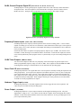
24-Bit, General Purpose Digital I/O (Channels A0 - A7, B0 - B7, and C0 - C7)
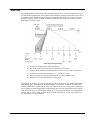
All DaqTemps have 24-bit, general purpose, digital I/O that can be used to directly control and monitor
24 digital I/O lines. The 24-bit digital I/O is divided into three 8-bit ports, which are labeled: A0-A7,
B0-B7, and C0-C7. Each port can be programmed as an 8-bit group for either input or output.
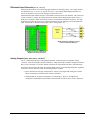
Digital I/O Section of DaqTemp Digital and Analog I/O Card
Frequency/Counter Inputs
(CNT0, CNT1, CNT2, and CNT3)
Each DaqTemp has four frequency/counter inputs that can be used for counting pulses. A 16-bit counter,
capable of counting up to 65,536 TTL-level transitions, resides behind each counter input. These inputs are
labeled CNT0, CNT1, CNT2, and CNT3 on the Digital and Analog I/O Terminal Block Card, as indicated
in the preceding figure.
Each of the four counters is capable of accepting frequency inputs of up to 10 MHz. The counters can be
cascaded to 32-bits, allowing over four billion counts to be totalized. As with all other inputs, the counters
can be read asynchronously under program control, or synchronously as a part of an analog and digital scan
group.
16-Bit Timer Outputs
(TMR0 and TMR1)
Two 16-bit timer outputs are built into every DaqTemp. Each timer-output can generate square waves
within a programmable frequency range of 16 Hz to 1 MHz. These outputs are labeled TMR0 and TMR1
on the Digital and Analog I/O Terminal Block Card, as indicated in the preceding figure.
Pacer Clock I/O (A/ICLK and A/OCLK)
All DaqTemp models have two signals that can be used as inputs for externally clocking the acquisition and
analog output DACs. A TTL input can be applied to A/ICLK that will start a scan every time a rising edge
occurs on the applied TTL input. Likewise, a TTL input can be applied to A/OCLK that will update the
DAC outputs every time a rising edge occurs on the applied TTL input. The pacer clock connection points
are indicated in the preceding figure. When using the internal pacer clock generator, the A/ICLK and the
A/OCLK can each be programmed as an output.
Hardware Trigger Input (TTLTRG)
All DaqTemp models have a TTLTRG input that can be used to trigger the start of an acquisition. The
connection point is indicated in the preceding figure.
Power Output
(+5V, DGND)
All DaqTemp models have a power output connection on the Digital and Analog IO card. The power
supplied has a voltage of 5V (+/-10%) and is sourced from the computer where the DaqTemp PCI board is
installed. No more than 500mA should be sourced out of this connection. See the preceding figure for the
power output connection points.
1-4
Overview & Theory of Operation
09-06-02
DaqTemp User’s Manual