1
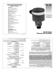
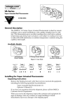
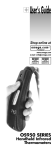
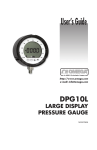
omega.com
™
®
®
®
LVCN-302
Set-Up Manual for Sump Model
User’s
Guide
MADE IN
Specifications:
Sensor Input: Isolated input accepts any type of 4-20 mA process signal. Loop power available up to
24VDC for 2 wire device
Input Power: 120VAC/900 mA; 24VDC unregulated/450 mA
Security Levels: 3 levels of access protect data changes with DIP switch on back
Control Circuits: Four Form C relays, 10.0 amp 125VAC (noninductive)
Switching Mode: Selectable, NO or NC states
Output & Input Connections: Terminal Connections are plug in Phoenix type
Programmed Memory: EEPROM - Loss of power will not affect existing programmed data
Mounting Format: Flush mounted anodized steel enclosure with eight (8) 10/32 studs and sealing
gasket; NEMA 4 graphic front panel; steel back pan housing.
Overall Dimensions: Tall: 16.75” (425 mm), Wide: 10.25” (250mm), Deep 2.25” (57mm),
Weight: 4.5 kg (10 lbs.)
LVCN-302 is a solid-state controller with a variety of unique control and display features. It’s designed to
simply present the crucial information, at a glance. It’s built to perform in all types of harsh industrial
environments as well as control alarms, pumps, solenoids, etc.
Topics covered in this manual
Displaying Your Tank’s Cross-Section
Security Levels / Select and Enter Data
Initial Set-Up / Eight Simple Steps
Sensor Connections / Schematics
Sending a 4-20 mA Signal to Other Devices
M3760/1201
LVCN-302 Features and Overview
Let's say your tank is 112 inches deep, and the transducer range of the sensor you’ve
chosen is 0-5 psi of water. 5 psi equals 138 inches H2O The pressure transducer is
located 11 inches off the bottom of the tank. With 51 inches of water in the tank you are
cavitating the pump, and at 108 inches of water you are facing probable flooding.
The goal is to maintain the liquid level between 90 and 65 inches using LVCN-302. The
following steps should be taken in order to display a 50 to 110 inch "window" of the tank,
while maintaining a liquid level range of 90 to 65 inches. High and low alarm output circuits
will be activated at 105 and 55 inches.
The Initial Set-up in Eight Easy Steps (see page 4)
describes in detail how to program LVCN-302 for your
specific application. To accomplish the above
installation, you would enter the following:
Transducer Range
Transducer Height
Upper Limit of Window
Lower Limit of Window
High Alarm/Fault Level
Sump ON Level
Sump OFF Level
Low Alarm/Fault Level
138.0 inches H2O
11.0
110.0
50.0
105.0
90.0
65.0
55.0
Tank Cross-Section Display with LVCN-302
110”
110” to 50” the critical
range in the tank you
need to monitor.
Upper Limit of Di
splay Window
110
High Alarm
Sump ON
®
Actual Liquid Level
95.3
Sump OFF
112”
Pump
Low Alarm
50”
Low
er L
im
123456
123456
11” OFFSET
it of
Disp
lay W
indo
w
50
Pressure
Transducer
Security Levels / Selecting and Accessing Data
Operator access to data modifications has three modes of security: View Only, Set Point
Changes Allowed and Programming. Each mode is selected from the back of the unit with a DIP
switch setting.
1234
1234
1234
1234
1234
1234
1234
1234
1234
1234
1234
1234
1234
1234
1234
ON
Programming Mode
1
ON
12345
12345
12345
1234
1234
1234
1234
1234
1234
1234
1234
1234
1234
1234
1
2
3
4
ON
1234
1234
1234
1234
1234
1234
1234
1234
1234
1234
1234
1234
1234
1234
1
View Only Mode
4
This mode, #2 ON, allows you to
change all four set points: the High &
Low Alarms, Make-up ON & Make-up
OFF.
3
Set Point Changes Allowed
2
This mode, #1 ON, allows you to
change all eight programmable
settings. It is used for initial set-up
and installation.
2
3
4
This mode, ALL OFF, prevents any
changes from being made. However,
all the information, except the
transducer range and transducer
offset, is available
by pressing SELECT.
Output & Input Terminal Connections
(All terminal connections are plug in Phoenix type)
Output
Terminals
#1-#3 Sump range
operates at same level
as #7-#9. Condiser it a
spare Form C sump
relay.
10.0 amp
Sensor Input
Power Supply
4. 4-20 mA (-)
3. 120 VAC - Com.
2. Ground
1. 120 VAC - Hot
3. 4-20 mA (+)
2. Ground
10.0 amp
10.0 amp
10.0 amp
Output Terminals
12. High Level N.C.
11. High Level Com
10. High Level N.O.
9. Sump ON N.C.
8. Sump ON Com
7. Sump ON N.O.
6. Low Level N.C.
5. Low Level Com
4. Low Level N.O.
3. Sump ON N.C.
2. Sump ON Com
1. Sump ON N.O.
120 VAC
Power Supply
1. + 24 VDC Output
24 Volt DC
Power Supply
(Unregulated)
Power Supply
3. 24 VDC - Neg (-)
2. Ground
1. 24 VDC - Pos (+)
NOTE: Terminal #1
provides power for
loop powered sensors.
Initial Set-Up in Eight Easy Steps
PROGRAMMING MODE
ON
12345
12345
12345
1234
1234
1234
1234
1234
1234
1234
1234
1234
1234
1234
1
2
3
4
The initial set-up requires you to change the DIP switch to Programming Mode, #1
ON. After the initial set-up, select the DIP switch settings for View Mode or Set
Point Changes Allowed. (More detail on Page 3.) Holding down the INCREASE or
DECREASE arrow for 3 seconds increases the scrolling speed of the numbers on
the display.
1. - Setting the Transducer Range Press the SELECT button on the graphic face - RANG
will appear in the display. A few seconds later, the display will convert to R___. The
Transducer Range of the input device needs to be entered, using the INCREASE or
DECREASE arrow. The Transducer Range is determined by the manufacturer of the device. It is
printed on the device, typically in either psi, inches of water or inches mercury. It is not the
height of the tank you are controlling.
For example: if you want to display a 120” tank of water in inches and have a transducer that has
a manufacturer’s range of 0-5 psi, you would use the following formula:
(5.0 psi water) (27.7 inches)
= 138.5 inches
1.0 specific gravity of water
( Note: 1psi water = 27.7” )
2. - Setting Offset / Transducer Height Press the SELECT button again and OFST will
appear in the display. A few seconds later, the display will convert to L___
L___. Enter the
Transducer Height by pressing the INCREASE or DECREASE arrow. Transducer Height is the
location of the transducer from the bottom of the tank, or if you are using a bubbler it is to the
bottom of the bubbler stand pipe.
3. - Selecting the Upper Cross-Section Press the SELECT button again - the Upper Limit
small numeric window display will begin to flash and the main display will convert to P___
P___. The
Upper Limit display level needs to be entered, using the INCREASE or DECREASE arrow. This is
the “window” or cross-section of the tank you want to see displayed on the vertical bar display. It is
not a control or alarm level.
This is one of the unique features of LVCN-302. You can select to display any portion of the height
of your tank. For example: Suppose you have a 120” tall tank that you want to control. Filters and
pumps occupy the bottom 50 inches, and you don’t want the level to ever go above 105”. At the
same time, you want to display the crucial operating range of your tank, including make-up levels,
high/low alarms and the actual level. To select the highest resolution of this crucial range on the
bar display, you would enter the Upper Limit P___ at 110” and the Lower Limit P___ at 50”.
You can select to display any cross-section you require for the installation.
4. - Selecting the Lower Cross-Section Press the SELECT button again - the Lower Limit
small numeric window display will begin to flash and the main display will convert to P___
P___. The
Lower Limit display level needs to be entered, using the INCREASE or DECREASE arrow. This is
the window or cross-section of the tank you want to see on the bar graph display. It is not a control
or alarm level. (See the above For example.)
NOTE: The previous four steps are protected from data changes when you choose
either one of the other security modes. The next four steps are accessible to changes in
either the Programming Mode (at the initial set-up) or with Set Point Changes Allowed
mode selected.
5. - Entering the High Alarm Level Press the SELECT button again - the High Level Alarm Point
indicator LED on the graphic face and the top RED line in the bar graph display will flash. P___ appears
in the display. Enter the level, using the INCREASE or DECREASE arrow to set the desired level. When
this point or level is reached, it will indicate a High Level Alarm has been reached and activate the control
circuit/device you have designed into your system.
6. - Entering the Sump ON Level Press the SELECT button again - the yellow Sump ON indicator
LED will flash along with the YELLOW line in the bar graph. P___ appears in the display. Enter the
level, using the INCREASE or DECREASE arrow to set the desired Sump ON level. When this point or
level is reached, LVCN-302 will deactivate the differential output relay to the control circuit/
device you have designed into your system.
7. - Entering the Sump OFF Level Press the SELECT button again - the Sump OFF indicator LED
and the ORANGE line in the bar graph will flash. P___ appears in the display. Enter the Sump OFF
level, using the INCREASE or DECREASE arrows. When this point or level is reached, LVCN-302 will
activate the differential output(s) to the control circuit/device you have designed into your system.
8. - Entering the Low Alarm Level Press the SELECT button again - the Low Level Alarm Point
indicator LED on the graphic face and the top RED line in the bar graph display will flash. P___ appears
in the display. Enter the Low Alarm Level, using the INCREASE or DECREASE arrow. When this point or
level is reached, it will indicate a Low Level Alarm has been reached and activate the control circuit/device
you have designed into your system.
Sensor Input Connections / Schematics
Signal Power Supplied by LVCN-302 (Loop Powered)
12. High Level N.C.
Typical Form-C Relay Connection
11. High Level Com
4. 4-20 mA ( - )
4.
3. 4-20 mA ( + )
3.
2. Ground
1. + 24 VDC Out
10. High Level N.O.
Jumper #4 to #2
4-20mA ( +)
2.
123456
123456
Level Input
123456
123456 Transducer
+
1.
(Transmitter)
+24 VDC Output
Sensor Input
Terminal
4.
3. 4-20 mA ( + )
3.
2. Ground
-
9.
8. Sump ON Com
8.
7. Sump ON N.O.
7.
6. Low Level N.C.
5. Low Level Com
4. Low Level N.O.
3. Sump ON N.C.
3.
2. Sump ON Com
2.
1. Sump ON N.O.
1.
4. 4-20 mA ( - )
+
123456
+
123456
123456
123456
-
3. 4-20 mA ( + )
Level Input
Transducer
2. Ground
(Transmitter)
1. + 24 VDC Out
1. + 24 VDC Out
Sensor Input
Terminal
Form - C
10.0 Amp @ 120 VAC
(noninductive)
Relay operates at
same level as #7-#9.
Consider it a spare
Form C sump relay.
Sending 4-20ma Signal to Other Devices
Signal Power Supplied by Other Source
4. 4-20 mA ( - )
9. Sump ON N.C.
Sensor Input
Terminal
LVCN-302
Sensor Input
4.
Sensor Device
-
3.
- +
-
+
External
Power
Supply
+
PLC
-
+
Other Helpful Features of LVCN-302
Interrupted 4-20 mA Signal from Sensor
Whenever the 4-20 mA signal from the sensor device
is lost because of an open wire or device malfunction,
an ERR3 message is displayed in the Actual Liquid
Level window. Additionally, the entire bar display will
flash red and green.
Over &/or Under 4-20 mA signal received
When the input sensor is sending a 4.0 mA signal, the
Actual Liquid Level display will show a \/ character in
the first digit of the display.
Actual Liquid Level
00.0
Process Signal
Input is 4.0 mA, but
not an open wire.
Actual Liquid Level
00.0
Process Signal
Input is 20.0 mA
See above for open wire
Software Version Numbers
The version number of your LVCN-302 unit is
shown in the Actual Liquid Level display window
when you power up the unit. If your unit has
version 2.8, you will see in the window LV 2.8
Programmed data cannot be lost
All the data and logic are written to a permanent
EEPROM, which will retain your data in the
event the power supply is disconnected. There
is no battery on the board to maintain the
data in the EEPROM.
omega.com
®
Servicing Europe:
OMEGAnet ® Online Service
www.omega.com
Internet e-mail
[email protected]
Servicing North America:
USA:
ISO 9001 Certified
Canada:
One Omega Drive, Box 4047
Stamford CT 06907-0047
Tel: (203) 359-1660
e-mail: [email protected]
976 Bergar
Laval (Quebec) H7L 5A1
Tel: (514) 856-6928
e-mail: [email protected]
FAX: (203) 359-7700
FAX: (514) 856-6886
Benelux:
Postbus 8034, 1180 LA Amstelveen, The Netherlands
Tel: +31 (0)20 3472121
FAX: +31 (0)20 6434643
Toll Free in Benelux: 0800 0993344
e-mail: [email protected]
Czech Republic:
Rudé armády 1868, 733 01 Karviná 8
Tel: +420 (0)69 6311899
FAX: +420 (0)69 6311114
Toll Free: 0800-1-66342
e-mail: [email protected]
France:
9, rue Denis Papin, 78190 Trappes
Tel: +33 (0)130 621 400
Toll Free in France: 0800-4-06342
e-mail: [email protected]
Germany/Austria: Daimlerstrasse 26, D-75392 Deckenpfronn, Germany
Tel: +49 (0)7056 9398-0
FAX: +49 (0)7056 9398-29
Toll Free in Germany: 0800 639 7678
e-mail: [email protected]
For immediate technical or application assistance:
USA and Canada: Sales Service: 1-800-826-6342 / 1-800-TC-OMEGA®
Customer Service: 1-800-622-2378 / 1-800-622-BEST®
Engineering Service: 1-800-872-9436 / 1-800-USA-WHEN®
TELEX: 996404 EASYLINK: 62968934 CABLE: OMEGA
Mexico:
En Espan˜ol: (001) 203-359-7803
FAX: (001) 203-359-7807
FAX: +33 (0)130 699 120
United Kingdom:
ISO 9002 Certified
e-mail:[email protected]
[email protected]
One Omega Drive, River Bend Technology Centre
Northbank, Irlam, Manchester
M44 5BD United Kingdom
Tel: +44 (0)161 777 6611
FAX: +44 (0)161 777 6622
Toll Free in United Kingdom: 0800-488-488
e-mail: [email protected]
It is the policy of OMEGA to comply with all worldwide safety and EMC/EMI regulations that apply. OMEGA is
constantly pursuing certification of its products to the European New Approach Directives. OMEGA will add the
CE mark to every appropriate device upon certification.
MADE IN
The information contained in this document is believed to be correct, but OMEGA Engineering, Inc. accepts
no liability for any errors it contains, and reserves the right to alter specifications without notice.
WARNING: These products are not designed for use in, and should not be used for, patient-connected applications.
WARRANTY/DISCLAIMER
OMEGA ENGINEERING, INC. warrants this unit to be free of defects in materials and workmanship for a period of 13 months from date of
purchase. OMEGA’s WARRANTY adds an additional one (1) month grace period to the normal one (1) year product warranty to cover handling
and shipping time. This ensures that OMEGA’s customers receive maximum coverage on each product.
If the unit malfunctions, it must be returned to the factory for evaluation. OMEGA’s Customer Service Department will issue an Authorized Return
(AR) number immediately upon phone or written request. Upon examination by OMEGA, if the unit is found to be defective, it will be repaired or
replaced at no charge. OMEGA’s WARRANTY does not apply to defects resulting from any action of the purchaser, including but not limited to
mishandling, improper interfacing, operation outside of design limits, improper repair, or unauthorized modification. This WARRANTY is VOID if
the unit shows evidence of having been tampered with or shows evidence of having been damaged as a result of excessive corrosion; or current, heat,
moisture or vibration; improper specification; misapplication; misuse or other operating conditions outside of OMEGA’s control. Components which
wear are not warranted, including but not limited to contact points, fuses, and triacs.
OMEGA is pleased to offer suggestions on the use of its various products. However, OMEGA neither assumes responsibility for any omissions or errors nor
assumes liability for any damages that result from the use of its products in accordance with information provided by OMEGA, either verbal or written.
OMEGA warrants only that the parts manufactured by it will be as specified and free of defects. OMEGA MAKES NO OTHER WARRANTIES OR
REPRESENTATIONS OF ANY KIND WHATSOEVER, EXPRESS OR IMPLIED, EXCEPT THAT OF TITLE, AND ALL IMPLIED WARRANTIES
INCLUDING ANY WARRANTY OF MERCHANTABILITY AND FITNESS FOR A PARTICULAR PURPOSE ARE HEREBY DISCLAIMED.
LIMITATION OF LIABILITY: The remedies of purchaser set forth herein are exclusive, and the total liability of OMEGA with respect to this order, whether
based on contract, warranty, negligence, indemnification, strict liability or otherwise, shall not exceed the purchase price of the component upon which
liability is based. In no event shall OMEGA be liable for consequential, incidental or special damages.
CONDITIONS: Equipment sold by OMEGA is not intended to be used, nor shall it be used: (1) as a “Basic Component” under 10 CFR 21 (NRC),
used in or with any nuclear installation or activity; or (2) in medical applications or used on humans. Should any Product(s) be used in or with any
nuclear installation or activity, medical application, used on humans, or misused in any way, OMEGA assumes no responsibility as set forth in our
basic WARRANTY/DISCLAIMER language, and, additionally, purchaser will indemnify OMEGA and hold OMEGA harmless from any liability or
damage whatsoever arising out of the use of the Product(s) in such a manner.
RETURN REQUESTS / INQUIRIES
Direct all warranty and repair requests/inquiries to the OMEGA Customer Service Department. BEFORE RETURNING ANY PRODUCT(S) TO
OMEGA, PURCHASER MUST OBTAIN AN AUTHORIZED RETURN (AR) NUMBER FROM OMEGA’S CUSTOMER SERVICE
DEPARTMENT (IN ORDER TO AVOID PROCESSING DELAYS). The assigned AR number should then be marked on the outside of the return
package and on any correspondence.
The purchaser is responsible for shipping charges, freight, insurance and proper packaging to prevent breakage in transit.
FOR WARRANTY RETURNS, please have the following
information available BEFORE contacting OMEGA:
1. Purchase Order number under which the product was
PURCHASED,
2. Model and serial number of the product under warranty, and
3. Repair instructions and/or specific problems relative to the
product.
FOR NON-WARRANTY REPAIRS, consult OMEGA for current
repair charges. Have the following information available BEFORE
contacting OMEGA:
1. Purchase Order number to cover the COST of the repair,
2. Model and serial number of the product, and
3. Repair instructions and/or specific problems relative to
the product.
OMEGA’s policy is to make running changes, not model changes, whenever an improvement is possible. This affords our customers the latest in technology and engineering.
OMEGA is a registered trademark of OMEGA ENGINEERING, INC.
© Copyright 2001 OMEGA ENGINEERING, INC. All rights reserved. This document may not be copied, photocopied, reproduced, translated, or reduced to any electronic
medium or machine-readable form, in whole or in part, without the prior written consent of OMEGA ENGINEERING, INC.
M3760/1201