1
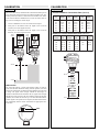
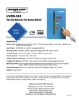
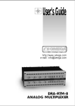
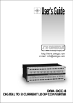
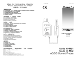
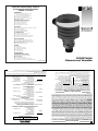
MADE
IN
USA
WARRANTY/DISCLAIMER
OMEGA ENGINEERING, INC. warrants this unit to be free of defects in materials and workmanship for a
period of 13 months from date of purchase. OMEGA Warranty adds an additional one (1) month grace
period to the normal one (1) year product warranty to cover handling and shipping time. This ensures
that OMEGA’s customers receive maximum coverage on each product.
If the unit should malfunction, it must be returned to the factory for evaluation. OMEGA’s Customer Service
Department will issue an Authorized Return (AR) number immediately upon phone or written request. Upon
examination by OMEGA, if the unit is found to be defective it will be repaired or replaced at no charge.
OMEGA’s WARRANTY does not apply to defects resulting from any action of the purchaser, including but not
limited to mishandling, improper interfacing, operation outside of design limits, improper repair, or unauthorized modification. This WARRANTY is VOID if the unit shows evidence of having been tampered with or
shows evidence of being damaged as a result of excessive corrosion; or current, heat, moisture or vibration;
improper specification; misapplication; misuse or other operating conditions outside of OMEGA’s control.
Components which wear are not warranted, including but not limited to contact points, fuses, and triacs.
OMEGA is pleased to offer suggestions on the use of its various products. However, OMEGA neither
assumes responsibility for any omissions or errors nor assumes liability for any damages that result
from the use of its products in accordance with information provided by OMEGA, either verbal or written. OMEGA warrants only that the parts manufactured by it will be as specified and free of defects.
OMEGA MAKES NO OTHER WARRANTIES OR REPRESENTATIONS OF ANY KIND WHATS0EVER,
EXPRESSED OR IMPLIED, EXCEPT THAT OF TITLE, AND ALL IMPLIED WARRANTIES INCLUDING ANY
WARRANTY OF MERCHANTABILITY AND FITNESS FOR A PARTICULAR PURPOSE ARE HEREBY DISCLAIMED. LIMITATION OF LIABILITY: The remedies of purchaser set forth herein are exclusive and the
total liability of OMEGA with respect to this order, whether based on contract, warranty, negligence,
indemnification, strict liability or otherwise, shall not exceed the purchase price of the component
upon which liability is based. In no event shall OMEGA be liable for consequential, incidental or special damages.
CONDITIONS: Equipment sold by OMEGA is not intended to be used, nor shall it be used: (1) as a “Basic
Component” under 10 CFR 21 (NRC), used in or with any nuclear installation or activity; or (2) in medical
applications or used on humans. Should any Product(s) be used in or with any nuclear installation or activity,
medical application, used on humans, or misused in any way, OMEGA assumes no responsibility as set forth
in our basic WARRANTY / DISCLAIMER language, and additionally, purchaser will indemnify OMEGA and
hold OMEGA harmless from any liability or damage whatsoever arising out of the use of the Product(s) in
such a manner.
RETURN REQUESTS / INQUIRIES
Direct all warranty and repair requests/inquiries to the OMEGA Customer Service
Department. BEFORE RETURNING ANY PRODUCT(S) TO OMEGA, PURCHASER MUST
OBTAIN AN AUTHORIZED RETURN (AR) NUMBER FROM OMEGA’S CUSTOMER SERVICE
DEPARTMENT (IN ORDER TO AVOID PROCESSING DELAYS). The assigned AR number
should then be marked on the outside of the return package and on any correspondence.
The purchaser is responsible for shipping charges, freight, insurance and proper packaging
to prevent breakage in transit.
FOR WARRANTY RETURNS, please have
FOR NON-WARRANTY REPAIRS, consult
the following information available BEFORE
OMEGA for current repair charges. Have
contacting OMEGA:
the following information available
BEFORE contacting OMEGA:
1. P.O. number under which the product
was PURCHASED,
1. P.O. number to cover the COST
of the repair,
2. Model and serial number of the product
under warranty, and
2. Model and serial number of product, and
3. Repair instructions and/or specific
3. Repair instructions and/or specific
problems relative to the product.
problems relative to the product.
USA:
ISO 9001 Certified
Canada:
omega.com
TM
OMEGA®
OMEGAnet On-Line Service
http://www.omega.com
SM
Internet e-mail
[email protected]
Servicing North America:
One Omega Drive, Box 4047
Stamford, CT 06907-0047
Tel: (203) 359-1660
e-mail: [email protected]
FAX: (203) 359-7700
976 Bergar
Laval (Quebec) H7L 5A1
Tel: (514) 856-6928
e-mail: [email protected]
FAX: (514) 856-6886
For immediate technical or application assistance:
USA and Canada:
Mexico and
Latin America:
Sales Service: 1-800-826-6342 / 1-800-TC-OMEGASM
Customer Service: 1-800-622-2378 / 1-800-622-BESTSM
Engineering Service: 1-800-872-9436 / 1-800-USA-WHENSM
TELEX: 996404 EASYLINK: 62968934 CABLE: OMEGA
Tel: (95) 800-TC-OMEGASM
En Espan˜ol: (203) 359-1660 ext: 2203
FAX: (95) 203-359-7807
e-mail: [email protected]
Servicing Europe:
Benelux:
Postbus 8034, 1180 LA Amstelveen, The Netherlands
Tel: (31) 20 6418405
FAX: (31) 20 6434643
Toll Free in Benelux: 06 0993344
e-mail: [email protected]
9, rue Denis Papin, 78190 Trappes
Tel: (33) 130-621-400
Toll Free in France: 0800-4-06342
e-mail: [email protected]
France:
Ostravska 767, 733 01 Karvina
Tel: 42 (69) 6311899
e-mail: [email protected]
Czech Republic:
FAX: 42 (69) 6311114
FAX: (33) 130-699-120
Germany/Austria: Daimlerstrasse 26, D-75392 Deckenpfronn, Germany
Tel: 49 (07056) 3017
FAX: 49 (07056) 8540
Toll Free in Germany: 0130 11 21 66
e-mail: [email protected]
United Kingdom:
ISO 9002 Certified
25 Swannington Road,
P.O. Box 7, Omega Drive,
Broughton Astley, Leicestershire,
Irlam, Manchester,
LE9 6TU, England
M44 5EX, England
Tel: 44 (1455) 285520
Tel: 44 (161) 777-6611
FAX: 44 (1455) 283912
FAX: 44 (161) 777-6622
Toll Free in England: 0800-488-488
e-mail: [email protected]
It is the policy of OMEGA to comply with all worldwide safety and EMC/EMI regulations that apply. OMEGA is constantly
pursuing certification of its products to the European New Approach Directives. OMEGA will add the CE mark to every
appropriate device upon certification.
The information contained in this document is believed to be correct but OMEGA Engineering, Inc. accepts no liability for any errors it contains, and reserves the right to alter specifications without notice.
WARNING: These products are not designed for use in, and should not be used for, patient connected applications.
M-3444 / 0799
Metering & Control Instrumentation
Refractometers
Pumps & Tubing
Air, Soil & Water Monitors
Industrial Water & Wastewater Treatment
pH, Conductivity & Dissolved Oxygen Instruments
OMEGA’s policy is to make running changes, not model changes, whenever an improvement is possible.
This affords our customers the latest in technology and engineering.
OMEGA is a registered trademark of OMEGA ENGINEERING, INC.
© Copyright 1996 OMEGA ENGINEERING, INC. All rights reserved. This document may not be copied,
photocopied, reproduced, translated, or reduced to any electronic medium or machine-readable form, in whole or
in part, without prior written consent of OMEGA ENGINEERING, INC.
M
U
M
U
M
U
M
U
M
U
M
U
Ultrasonic Level Transmitter
LVU-90 Series
ENVIRONMENTAL
MONITORING AND CONTROL
M
U
M
U
M
U
M
U
M
U
Heating Cable
Cartridge & Strip Heaters
Immersion & Band Heaters
Flexible Heaters
Laboratory Heaters
HEATERS
M
U
M
U
M
U
M
U
M
U
Data Acquisition & Engineering Software
Communications-Based Acquisition Systems
Plug-in Cards for Apple, IBM & Compatibles
Datalogging Systems
Recorders, Printers & Plotters
DATA ACQUISITION
M
U
M
U
M
U
M
U
pH Electrodes, Testers & Accessories
Benchtop/Laboratory Meters
Controllers, Calibrators, Simulators & Pumps
Industrial pH & Conductivity Equipment
pH/CONDUCTIVITY
M
U
M
U
M
U
M
U
http://www.omega.com
e-mail: [email protected]
Rotameters, Gas Mass Flowmeters & Flow Computers
Air Velocity Indicators
Turbine/Paddlewheel Systems
Totalizers & Batch Controllers
FLOW/LEVEL
M
U
M
U
M
U
M
U
®
Transducers & Strain Gauges
Load Cells & Pressure Gauges
Displacement Transducers
Instrumentation & Accessories
PRESSURE, STRAIN AND FORCE
M
U Thermocouple, RTD & Thermistor Probes,
Connectors, Panels & Assemblies
M
U Wire: Thermocouple, RTD & Thermistor
M
U Calibrators & Ice Point References
M
U Recorders, Controllers & Process Monitors
M
U Infrared Pyrometers
TEMPERATURE
Where Do I Find Everything I Need for
Process Measurement and Control?
OMEGA…Of Course!
User’s Guide
SPECIFICATIONS
Step One
Range:
Accuracy:
Resolution:
Frequency:
Pulse rate:
Beam width:
Dead band:
Supply voltage:
Max loop resistance:
Signal output:
Fail-safe diagnostics:
3.6" to 6' (9 cm to 1.8 m)
± .25% of span in air
0.125” (3 mm)
83 kHz (nominal)
2 pulses per second
8° conical
3.6” (9 cm)
12-36 VDC
600 Ohms @ 36 VDC
4-20 mA, 12-36 VDC
Reverts to 22 mA
LED flashing
Temperature rating: F: -40º to 140º
C: -40º to 60º
Temp. compensation: Automatic over entire range
Pressure rating:
30 psi (2 bar) @ 25 °C., derated @ 1.667 psi
(0.113 bar) per °C. above 25 °C.
Enclosure rating:
NEMA 4X / IP65
Enclosure material: Polypropylene, U.L. 94VO
Transducer materials: PVDF
Mounting threads:
3/4” NPT for LVU-91
3/4” G for LVU-92
Mounting gasket:
Viton (3/4" G) LVU-92 only
Conduit connection: 1/2” NPT
CE compliance:
EN 50082-2 immunity
EN 55011 emission
(pending)
About Ultrasonic Technology:
An ultrasonic sound wave is pulsed five times per second from the
base of the transducer. The sound wave reflects against the process
medium below and returns to the transducer. The microprocessor
based electronics measures the time of flight between the sound generation and receipt, and translates this figure into the distance between
the transmitter and process medium below.
6’ Range
POWER
8° Cone
Radius
35
Temperature/Pressure Derating
Unacceptable
Range
30
25
20
15
Acceptable
Range
10
05
00
-40
-20
00
20
Temperature (°C)
40
60
Ambient Sensor Temperature (°C)
Operating Pressure (psi)
4-20 mA
Maximum Temperature/Voltage Derating
Continuous 20 mA Curve
100
Unacceptable
Range
80
60
Acceptable
Range
40
20
0
12
16
20
24
28
32
Operating Voltage (VDC)
36
Range
Radius
Radius
Feet
Inches
cm
1
2
3
4
5
6
1.2
2.1
2.9
3.7
4.9
5.4
3.1
5.2
7.3
9.5
11 . 6
13.7
Max. Series Resistance (Ohms)
12-36 VDC
GND
(-) (+)
700
600
500
400
300
200
100
000
Electrical Loading Limits
Unacceptable
Range
Acceptable
Range
18
24
30
Supply Volyage (VDC)
36
SAFETY PRECAUTIONS
Step Two
WIRING
Step Three
About this Manual:
Wiring to Terminal:
PLEASE READ THE ENTIRE MANUAL PRIOR TO
INSTALLING OR USING THIS PRODUCT. This manual
includes information on the LVU-90 series continuous non-contact
level transmitter from OMEGA. Please refer to the part number
located on the sensor label to verify the exact model which you
have purchased.
The LVU-90 arrives from the factory pre-calibrated and pre-assembled. Use the following instructions below for wiring to the LVU-90.
1. First, remove the cap of the transmitter:
2. Look for the terminal block with two terminals.
User’s Responsibility for Safety:
POWER
12-36 VDC
(-) (+)
GND
OMEGA manufactures a wide range of liquid level sensors and
technologies. While each of these sensors is designed to operate in
a wide variety of applications, it is the user’s responsibility to select
a sensor model that is appropriate for the application, install it
properly, perform tests of the installed system, and maintain all
components. The failure to do so could result in property damage
or serious injury.
4-20 mA
Proper Installation and Handling:
Because this is an electrically operated device, only properlytrained staff should install and/or repair this product. Use a proper
sealant with all installations. Note: Always install the 3/4” Viton
gasket with the LVU-92. The G threaded version will not seal
unless the gasket is installed properly. Never overtighten the transmitter within the fitting. Always check for leaks prior to system
start-up.
Wiring and Electrical:
A supply voltage of 12-36 VDC is used to power the transmitter.
The sensor systems should never exceed a maximum of 36 volts
DC. Electrical wiring of the sensor should be performed in accordance with all applicable national, state, and local codes.
Material Compatibility:
The enclosure is made of Polypropylene (PP). The transducer is
made of Polyvinylidene Fluoride (PVDF). Make sure that the
model which you have selected is chemically compatible with the
application liquids it will contact.
Enclosure:
While the transmitter housing is liquid-resistant when installed
properly, it is not designed to be immersed. It should be mounted
in such a way that the enclosure and diaphragm do not come into
contact with fluid.
Make a Fail-Safe System:
Design a fail-safe system that accommodates the possibility of
transmitter or power failure. In critical applications, OMEGA recommends the use of redundant backup systems and alarms in addition to the primary system.
Flammable, Explosive and Hazardous Applications:
The LVU-90 series transmitter systems should not be used within
flammable or explosive applications.
Warning
Always install the 3/4" Viton gasket with the LVU-92. The LVU92 G threaded version will not seal unless the gasket is installed
properly.
3. Remove the terminal block to wire the LVU-90. The terminal to
the right is positive and the terminal to the left is negative.
4. When finished attaching the wires, assemble the LVU-90 using
steps 1 - 3 in reverse.
WIRING
INSTALLATION
Step Four
Step Five
Follow the instructions in Step 3 for wiring to the LVU-90.
The LVCN-90 transmitter may be installed through the top wall of a
tank. Installation requires a 3/4" NPT fitting or blind flange.
1. Wiring to an OMEGA Continuous Controller (LVCN-51):
Connect the (+) terminal to the positive 24 VDC, 25 mA terminal
on the controller. Connect the (-) terminal to the GND terminal on
the continuous controller (See illustration below). Check LVCN51 instruction manual for setting the LVCN-51 for loop powered
operation.
1. Install the appropriate 3/4" fitting in the top wall of the tank. Prior
to installation, make sure that the fitting has been installed properly and checked for leaks. Use a proper sealant at the time of
installation to ensure a liquid-tight seal. Secondly, make sure that
the fitting’s threads are not damaged or worn.
POWER
- +
0%
INPUT
RLY2B
4-20 mA
R E L AY 2
DELAY
RLY2A
OFF SET
12-36 VDC
GND
INVERT
RLY1
ON OFF
(-) (+)
R E L AY 1
LATCH
SPAN
P W R
100%
INVERT
DELAY
E A S Y CAL
4
20
OP
UP
DOWN
SET
2. Insert the Transmitter into the fitting and tighten to hand tight.
3. Always check for leaks prior to system start-up. To ensure proper
installation, a complete leak test and simulation of actual process
conditions should be preformed.
Flange
Installation
Fitting
Installation
2. Wiring to a Two-Wire Loop Powered Indicator:
The LVCN-90 requires 12-36 VDC power and an indicator which
receives a 4-20 mA current input. Connect the (+) terminal of the
LVCN-90 transmitter to the positive VDC terminal on the power
supply. Connect the (-) terminal on the LVCN-90 to the (+) terminal on the loop indicator. Connect the (-) of the loop indicator
to the (-) of the power supply (See illustration below).
POWER
DC Power
Supply
12-36 VDC
+
12-36 VDC
GND
(-) (+)
-
-
+
4-20 mA
- +
Warning
Do not install the LVCN-90 in pressurized applications above 30
psi.
DC Power
Supply
6
12-36 VDC
4
5
12-36 VDC
GND
(-) (+)
+
-
3
2
4-20 mA
- +
1
Use a proper sealant at the time of installation to ensure a liquidtight seal. Secondly, make sure that the fitting’s threads are not
damaged or worn.
Avoid
Interference from
side of tank
Do not
install at
an angle
Avoid
Interference from
obstructions in
tank
LVCN-90 will
not operate in
vacuum
250Ω
POWER
Typical PLC
3. Wiring to a Typical PLC:
The LVCN-90 requires a PLC which provides a 12-36 VDC excitation and receives a 4-20 mA current input. Connect the (+) terminal of the LVCN-90 transmitter to the positive VDC power terminal. Connect the (-) terminal on the LVCN-90 to the (+) channel on the PLC. Connect the (-) of the PLC to the (-) of the power
terminal (See illustration below).
Always install the 3/4" Viton gasket with the LVCN-92. The
LVCN-92 G threaded version will not seal unless the gasket is
installed properly.erly and checked for leaks.
0
A
* 250 Ω resistor typically internal to PLC
VACUUM
CALIBRATION
CALIBRATION
Step Six
Step Seven
The LVCN-90 is factory calibrated with a fixed measurement span of
6 feet. The 4 mA position is located 72" from the transducer face. The
20 mA position is located 3.6 inches from the transducer face. Refer
to the current to distance and distance to current conversion charts in
step seven for reading the current output.
Current to Distance Conversion Chart (Nominal)
1. Connect a multimeter in series to read the current output.
2. Verify that as the distance from the liquid to the LVCN-90
increases, the current signal decreases.
3. Verify that as the distance from the liquid to the LVCN-90
decreases, the current signal increases.
Power
Supply
5
4
Power
Supply
6
19
20
mA
com
21
mA
(+)
com
(+)
Current Distance
Current Distance
inches
mA
inches
mA
inches
20
19
18
17
16
15
03.6
07.9
12.1
16.4
20.7
25.0
14
13
12
11
10
09
29.2
33.5
37.8
42.1
46.3
50.6
08
07
06
05
04
54.9
59.2
63.5
67.7
72.0
Distance to Current Conversion Chart (Nominal)
Distance Current
Distance Current Distance Current
inches
mA
inches
mA
inches
mA
3.6
06
12
18
24
20.0
19.4
18.0
16.6
15.2
30
36
42
48
54
13.8
12.4
11 . 0
09.6
08.2
60
66
72
06.8
05.4
04.0
3.6"
20 mA
72"
3.6"
20 mA
4 mA
LED Indication
The LVCN-90 features a single LED indicator which is used for
power and fail-safe indication. During normal operation, the LED
will be ON continuously to indicate that the transmitter has power and
a strong echo signal return strength. Should the LED begin to
FLASH, it indicates that the transmitter has no signal return strength
and the device has gone into a fail-safe condition. During the fail-safe
condition, the current will increase up to 22 mA and hold until the
acoustic signal is reacquired. Once reacquired, the LED will turn back
ON continuously and the current will indicate the appropriate measured value.
POWER
LED
12-36 VDC
GND
(-) (+)
4-20 mA
Current Distance
mA
72"
68.4"
4 mA
MAINTENANCE
Step Eight
General:
The LVCN-90 series level transmitter itself requires no periodic
maintenance except cleaning as required. It is the responsibility of the
user to determine the appropriate maintenance schedule, based on the
specific characteristics of the application liquids.
Cleaning Procedure:
1. Power: Make Sure that all power to the transmitter, controller
and/or power supply is completely disconnected.
2. Sensor Removal: In all through-wall installations, make sure that
the tank is drained well below the sensor prior to removal.
Carefully, remove the sensor from the installation.
3. Cleaning the Sensor: Use a soft bristle brush and mild detergent,
carefully wash the transducer of the LVCN-90. Do not use harsh
abrasives such as steel wool or sandpaper, which might damage
the transmitter's surface. Do not use incompatible solvents which
may damage the PVDF transducer or the transmitter’s PP body.
4. Sensor Installation: Follow the appropriate steps of installation as
outlined in the installation section of this manual.
Step Nine