1
Table of Contents
1
2
5
7
8
10
11
12
13
14
15
16
17
18
19
20
21
22
23
24
25
26
27
28
29
30
30
30
31
32
32
33
35
37
37
37
38
39
39
39
43
44
44
45
46
50
51
51
57
58
59
59
60
60
60
60
60
61
63
64
65
English
Important Information
Important Safety Precautions
Introducing the OLEVIA TV
Accessories
TV Installation And Connection Guide
Identifying Front Controls and Rear Panels
- Descriptions of Connector Types
- Turn the power on the TV
Installation
- Connecting to an Antenna or Video Equipment with Antenna Outlet
- Connecting to a Set-Top-Box with HDMI Cables
- Connecting to a Satellite Receiver or Cable Box with Component Connectors
- Connecting to a DVD Player with A/V or S Video Cables
- Connecting to a DVD Player with Component Cables
- Connecting to a DVD Player with HDMI Cables
- Connecting to a Satellite Receiver or Cable Box with A/V Cables
- Connecting to a VCR, PVR, or DV with A/V Cables
- Connecting to a Blue-Ray DVD Player or HD-Receiver with HDMI Cables and a
PC with VGA Cables
- Connecting to a D-VHS with HDMI Cables
- Connecting to a D-VHS with Component Cables
- Connecting to an Audio Receiver
- Connecting to a Home Theater System or Earphone Set
- Instruction for Uploading New Firmware
Remote Control Guide
Remote Function Keys & Description
Programming the Remote Control
Battery Installation
On Screen Display (OSD)
Introduction
Operating in the OSD
Initial Screen
PICTURE OSD Adjusting TV Picture Settings
- Description of Settings
- Selecting the Picture Mode
- Adjusting the Picture Quality
AUDIO OSD Adjusting Sound Quality
- Description of Settings
- Adjusting the Audio Settings
- MTS System for Stereo TV
SCREEN OSD Adjusting Screen Modes
- Description of Settings
- Changing the Screen Mode
- Selecting the Picture/Video Source
SETUP OSD Adjusting Personal TV Settings
- Description of Settings
- Searching the TV Channels
- Editing Channels
- Closed Caption Options
- Setting up Parental Control Password
- Activating the Parental Control Feature
- Resetting the Password
- Setting the Date and Time
- Setting the TV Timer
- Timeout Settings for OSD Menu
- TV OSD Languages
- Setting DPMS
- Setting LED Light
- Factory Default Option
- Displaying the Firmware Version
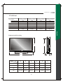
Specifications
Timing Mode for VGA and HDMI(PC)
Pixels Policy
Glossary
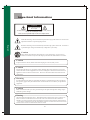
Import ant Inform ation
Caution
Risk of electronic shock
Do not open
To reduce the risk of electronic shock, do not remove cover (or back).
No user-serviceable parts inside.
Refer service to qualified Repair Technician or Repair Center.
Read the following context indicated by the following symbol to the left. It indicates
important literature in operating the product.
English
Read the following context indicated by the following symbol to the left. It indicates
a potential high voltage hazard that may compromise your safety.
Caution
Take caution when moving the product on a cart. Quick stops, excessive force,
and uneven surfaces may cause the display unit and cart combination to overturn.
Caution
To prevent electric shock, match wide blade of plug to wide slot, fully insert.
Caution
This product satisfies FCC regulations when shielded cables and connectors are used to
connect the unit to other equipment. Prevent electromagnetic interference from electrical
appliances such as radios and televisions. Please use shielded cables and connectors for
connections.
Warning
FCC Regulations state that any unauthorized changes or modifications to this equipment
not expressly approved by the manufacturer could void the user's authority to operate this
equipment.
Caution
Make sure that the cable system is grounded to provide protection against voltage surges
and built up static charges.
Warning
THIS TELEVISION IS EXTREMELY HEAVY -- IMPROPER HANDLING AND INSTALLATION CAN RESULT IN
INJURY TO PEOPLE AND PROPERTY DAMAGE TO THE STRUCTURE AND SURROUNDING PERSONAL
PROPERTY! WALL MOUNTING OF THIS TELEVISION SHOULD ONLY BE ATTEMPTED BY A PROFESSIONAL
-- ANY LIABILITY FOR PERSONAL INJURY OR PROPERTY DAMAGE CAUSED BY FAILED WALL MOUNTING
ATTEMPTS WILL NOT BE ACCEPTED BY THE MANUFACTURER!
01
Import ant Safety Precautions
Cleaning
Stand
Remember to unplug the AC cord from the AC outlet
before cleaning the display unit.
Then spray small amount original WINDEX window
clearer (blue stuff), not Ammonia-added clearer, on
cloth to clean the display.
Remember to use only soft cotton cloth such as an old
100% cotton T-shirt, not sponges brillo abrasive
material, to clean the display.
No drips allowed.
Do not place the display unit on an unstable
place. The TV may fall resulting in serious
personal injuries to nearby people as well as
damage to the display unit.
English
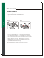
Ventilation
Do not cover or block these vents and openings located
on the top and back of the display. Inadequate ventilation
may cause overheating and shorten the lifespan of the display.
Do not place in an enclosed area such as a built-in shelf,
unless proper ventilation is provided or the manufacturer's
instructions are followed. Keep the distance of 10cm
minimum between the display unit and wall. Never install the
display unit as indicated in the picture below.
Air circulation is blocked
Air circulation is blocked
10cm
10cm
02
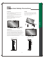
Important Safety Precautions
Never insert objects or spill liquid
into the display unit
Precautions when transporting the
display
Never insert any object into the display unit through
openings or spill liquid on the display unit. High
voltage flows in the display unit, and inserting an
object can cause electric shock and/or short internal
parts.
Carrying the display requires two or more people.
English
Keep away from water and moisture
Do not place the display in areas where moisture is
present or where the unit may get wet such as bathrooms, kitchen, pool area or in a wet basement.
Attachments
Do not use attachments not recommended by the
manufacturer. Use of inadequate attachments may
result in accidents to nearby poeple or to the unit.
Keep away from heat sources
Keep the display unit away from heat sources such
as radiators, heaters, stoves and other
heat-generating products.
Power source
This product must operate on a power source
specified on the specification label. If you are not
sure of the type of power supply used in your home,
consult your dealer or local power company. For
units designed to operate on batteries or another
power source, refer to the operating instructions.
The liquid crystal panel used in this
product is made of glass
Do not hit the panel. Be careful to prevent from
getting hurt by broken glass pieces in case the panel
breaks.
Follow operating instructions
AC cord protection
All operating instructions must be followed.
The AC cords must be routed properly to prevent
people from stepping on them or objects from resting
on them. Check the cords at the plugs and product.
Servicing
Do not attempt to service the display unit yourself.
Removing covers expose you to high voltage and
other dangerous conditions. Request a qualified
service technician to perform the service.
Overloading
Do not overload AC outlets or extension cords. It
may result in electric shock or start a fire.
03
Important Safety Precautions
Replacement parts
Reference Grounding component
In case the display unit needs replacement parts,
make sure that the service technician uses replacement
parts specified by the manufacturer, or those with
the same characteristics and performance as the
original parts. Use of unauthorized parts can result
in fire, electric shock and/or other danger.
Safety checks
Upon completion of service or maintenance, request
the service technician to perform safety checks to
ensure that the display unit is in proper operating
condition.
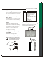
3
Ground clamps
4
Grounding conductors (NEC Section
810-21)
5
Antenna discharge unit (NEC Section
810-20)
6
Grounding clamp
7
Antenna lead-in wire
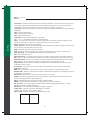
Please select the fit-sized screws and wire ropes to fasten
the display unit on the wall to prevent it from falling
immediately when the earthquake happens.
1.A liquid was spilled on the display unit or objects
have fallen into the display unit.
2.The display unit has been exposed to rain or water.
3.The display unit has been dropped or damaged.
Environment
The display unit only operates within the
temperature 0 C to 40 C.Operation outside of the
recommended may cause damage to your product.
When installing or realigning an
outside antenna system, extreme
care should be taken to keep from
touching such power lines or circuits.
Contact with them could be fatal.
7
6
5
4
3
1
Power service grounding electrode
system (NEC Art 250. Part H)
Prevent the display unit from falling
When the display unit displays an abnormal
condition, any noticeable abnormality in the display
unit indicates that the display unit needs servicing.
If any of the following conditions occurs, unplug
the AC cord from the AC outlet, and request a
qualified service person to perform repairs.
Warning
Electric service equipment
2
2
Antenna and satellite grounding
04
English
Repair
1
Introducing the OLEVIA TV
Welcome!
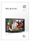
Thank you for purchasing a OLEVIA LCD HDTV.
This manual is to be used with the following model:
OLEVIA 2 Series
This manual is designed to help you through setting up and operating your
LCD HDTV as quickly as possible. The model and serial numbers are on the
back cover of your TV. Write these numbers in the space provided in this
manual for your records. Please read all the safety and operating instructions
carefully, and keep this manual for future reference.
Licensed Under U.S. Patent 4930160.
English
Owner's Record
The model and serial numbers are located at the rear of the display
unit, or on the side of the media receiver unit on the cartons
(white label). Record these numbers in the spaces provided below.
And register your product at www.olevia.com. Refer to them
whenever you call Syntax-Brillian Corporation or local dealer
regarding this product.
Model No.
Serial No.
05
Introducing the Olevia TV
OLEVIA LCD HDTV includes many features, you will enjoy throughout
the usage of your TV. These highlighted features include:
Fully Integrated HDTV (High Definition TV):
HDTV delivers a stunning picture far beyond the quality of standard
televisions. These programs offer crystal clear video with amazing
detail played with enhanced audio quality of digital television programs.
You can enjoy better sound and picture in movies, prime time TV shows,
and other HD broadcasts in dynamic television settings through cable,
satellite or even free broadcasts over the air.
HDMI and the HDMI logo are trademarks or registered trademarks of
HDMI Licensing, LLC.
Manufactured under license from Dolby Laboratories. Dolby and the
double-D symbol are registered trademarks of Dolby Laboratories.
Olevia and the Olevia logo are trademarks or registered trademarks of
Syntax-Brillian Corporation in the United States and other countries.
Corporate names, trademarks, registered trademarks, service marks,
symbols, and logos stated herein are property of their respective companies.
06
English
HDMI (High Definition Multimedia Interface):
The next generation of DVI, HDMI provides the best interface between
a DVD player and compatible products such as digital set top box for
uncompressed digital audio/video connections. When matched with a
OLEVIA TV, multi-channel digital audio signals, uncompressed DVI
digital video and intercommunication between high multimedia interfaces
are combined through a single interconnecting cable.
Accessories
Supplied Accessories
Remote control & batteries (AAA x 2)
English
Power cord x 1
User manual x1
QSG x 1
Warranty Card x 1
These items are all you need to set up and operate the TV in its
basic configuration.
Note: Most components (VCRs, DVD players, etc.) come with
the necessary cables to connect them. If you want to set up a
complex system, you may need to buy extra cables, connectors,
etc. Be sure to have these on hand before you start to connect
your system.
07
TV Installation and Connection Guide
Identifying Front and Rear Panels
Front Panel
For 242 / 247 Models
For 252 / 255 Models
English
IR Sensor
IR Sensor
ENTER
POWER
Turns display on/off.
ENTER
Press to enter to Sub-Menu, or select and confirm your setting.
MENU
Displays the On Screen Display(OSD) menu. In OSD menu, press it to return to the
previous screen or to exit.
CH / CH
Adjusts Channel. In the OSD menu, both keys are used to navigate within menu.
VOL+/VOL-
Adjusts Volume. In the OSD menu, both keys are used to navigate within menu.
Vol+ is used to select the highlighted option.
SOURCE
IR SENSOR
Press to switch the input sources.
Contains Infra-red light for digital data transmission by the remote control. Please
point remote control at IR Sensor for function.
08
POWER
TV Installation and Connection Guide
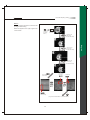
Identifying Front and Rear Panels
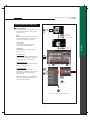
Rear Panel
1 Power Connections
The power cord connects here.
AC In
2 Computer / TV Signal Connections
English
RF Terminal
To receive signals from VHF / UHF antennas or a cable system
(For TV Models Only)
Component 1/2
(5 RCA jacks) Used to connect A/V equipment with component video outputs, such as
a DVD player, Digital Satellite Receiver, or compatible Video Game System.
R
Pr/Cr
L
Pb/Cb
Y
Video 1/2
R
AV
L
S-Video
NOTE: The component inputs have a superior quality of picture than the S-Video or AV
(composite video) inputs.
AV (Composite Video: 3 RCA jacks): Used to connect a VCR, Super VHS (S-VHS),
DVD player, or other video devices to the TV.
OR
S-Video : (1 DIN and 2 RCA jacks) Used to connect video devices to the TV.
However, they have a better quality of picture than a composite video signal.
Used to connect digital video equipment with a HDMI/DVI output.
HDMI/DVI
NOTE: Preferred connection for HDMI/DVI Satellite or Set-Top-Box equipment.
VGA/Audio Input
(PC) Port
R
L
Used for analog RGB signals from a personal computer. VGA has one set of Audio R/L inputs.
OR
As a computer input with VGA to RCA Adapter.
Audio Input
R
L
Firmware Upgrade
Port
To send an AV receiver or other equipment's connected audio signals to the TV
To allow firmware upgrades.
RS232C Port
Used to control the TV with automation devices.
Earphone
Used for audio output to earphone.
Coaxial/Optical
To send the TV's connected digital audio signals to an AV receiver or other equipment, such as
the amplifier
09
TV Installation and Connection Guide
Descriptions of Connector Types
You may find it necessary to use some of the following cable types during setup.
75-ohm Coaxial Cable
For TV/cable connection
S-Video Cable
Used for transferring video signal, which is split
into two signals, brightness and color.
Through this connection, you can view a better
picture than AV (Composite Video) connection.
Video (Yellow)
This connection is the most commonly found on
A/V equipment.
Left Audio (White)
Right Audio (Red)
Used for transferring video signal, which is split
into three signals, one brightness and two color.
Component Cable
Y (Green)
Pb/Cb (Blue)
Through this connection, you can view a better
high definition picture than S-Video or AV
(Composite Video) connection.
Pr/Cr (Red)
HDMI Cable
Used for transferring digital uncompressed video
and audio signals to the TV.
HDMI signal is purely digital and provides a
crystal clear technology better than component,
S-Video or Video connections. It is strongly
recommended to use this connection if you have
this function on your equipment.
10
English
Used for transferring audio and video signal.
Audio/Video Cable
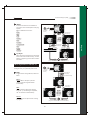
TV Installation and Connection Guide
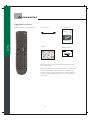
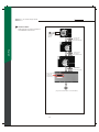
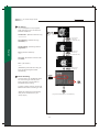
Turn the power on the TV
Please f ollow these steps to turn the power on to the TV.
1) Before connecting the Power cord, make sure all other connections are done first.
2) Connect the Power Cord from a Wall Outlet to the Power IN Port on the back of the TV as shown below.
Back of TV
Power
IN Port
Wall
Outlet
English
Power
Cord
A red or blue light on the front of the TV may turn on. If so, then skip step 3 and step 4. If the light is NOT
on, do Step 3.
Front of TV
Red or blue light
(also called "standby light").
Color and location depends on mode
3) If a red or blue light on the front of the TV is NOT on, press the Power Button on the back of the TV as
shown below. Now the light on the front turns on. In other words, the Power Button in the back must be
on for the light in the front to turn on.
Back of TV
POWER Button
(also called"master power switch")
4) Press the POWER Button on the front of the TV as shown below or on the remote control. Wait about
10 seconds for something to appear on-screen. Your TV is on and the red or blue light on the front turns
off automatically.
Front of TV
POWER Button
11
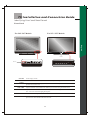
TV Installation and Connection Guide
Installation
In the following pages, you will find directions on how to install your tv and choice of video equipment.
Connecting to an Antenna or Video Equipment with Antenna outlet
Connecting to a Set-Top-Box with HDMI Cables (Preferred TV connection)
Connecting to a Satellite Receiver or Cable Box with Component Connectors
(Secondary Preferred after HDMI)
Connecting to a DVD Player with A/V or S Video Cables
Connecting to a DVD Player with HDMI Cables
Connecting to a Satellite Receiver or Cable Box with A/V Cables
Connecting to a VCR, PVR, or DV with A/V Cables
Connecting to a Blue-Ray DVD Player or HD-Receiver with HDMI Cables
and a PC with VGA Cables
Connecting to a D-VHS with HDMI Cables
Connecting to a D-VHS with Component Cables
Connecting to an Audio Receiver
Connecting to a Home Theater System or Earphone Set
Instruction for Uploading New Firmware
12
English
Connecting to a DVD Player with Component Cables
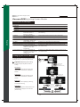
TV Installation and Connection Guide
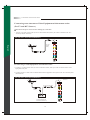
Connecting to an Antenna or Video Equipment with Antenna outlet
(For TV and DTV Source)
Disconnect all power sources before making any connection.
1. Connect a 75-ohm coaxial cable (or choice of Antenna Cable) from your cable or antenna to the TV's
Antenna jack (RF Terminal).
For 242 / 247 / 252 / 255 TFHD Models
Rear of TV
English
(75-ohm
coaxial
cable)
If connecting to Video Equipment with Antenna outlet
1. Connect a 75-ohm coaxial cable (or choice of Antenna Cable) from your cable or antenna to the Video
Equipment's IN jack.
2. Connect another 75-ohm coaxial cable from the Video Equipment's OUT jacks to the TV's Antenna jacks
(RF Terminal).
For 242 / 247 / 252 / 255 TFHD Models
Rear of TV
(75-ohm coaxial cable)
(75-ohm
coaxial
cable)
IN OUT
jack jack
(Video Equipment with
Antenna In/Out Socket)
13
TV Installation and Connection Guide
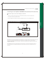
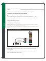
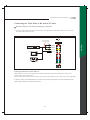
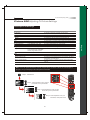
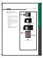
Connecting to a Set-Top-Box with HDMI Cables (Preferred TV connection)
Disconnect all power sources before making any connection.
1. Connect a 75-ohm coaxial cable (or choice of Antenna Cable) from your cable or antenna to the
Set-Top-Box's Antenna jack (RF Terminal).
2. Connect a HDMI cable from the Set-Top-Box's HDMI OUT jacks to the TV's HDMI IN jacks.
For 242 / 247 / 252 / 255 TFHD Models
English
Cable/
Satellite
(75-ohm
coaxial cable)
1
2
Set-Top-Box
HDMI cable
Rear of TV
Note: HDCP is a copy protected digital connection that receives analog or digital video and audio signals from
equipment with a HDMI output that features the HDCP function. HDMI allows the transfer of digital
uncompressed data to the TV. This connection is superior when compared to the Component, S Video or AV
(composite) connections.
Note: HDMI signal is purely digital and provides a better picture, it is better than component, S-Video or
Video connections. It is strongly recommended to use this connection if you have this function on your
equipment.
14
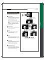
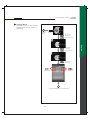
TV Installation and Connection Guide
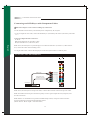
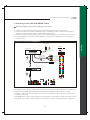
Connecting to a Satellite Receiver or Cable Box with Component
Connectors (Secondary Preferred after HDMI)
Disconnect all power sources before making any connections.
Use this method of connection if your Satellite Receiver or Cable Box has component (Y, Pb, Pr) jacks.
1.Using a component video cable, connect the Satellite Receiver or Cable Boxes' Y, Pb and Pr jacks to the Y,
Pb and Pr jacks on the TV.
English
Colors on Component Video connectors:
Y: Green
Pb (also identified as Cb, CB or B-Y): Blue
Pr (also identified as Cr, CR or R-Y): Red
Note: The Y, Pb and Pr jacks on your Satellite Receiver or Cable Box are sometimes labeled as Y, Cb and Cr,
or B-Y and R-Y. If so, connect the cables to the matching colors.
2.Using an Audio cable, connect the Satellite Receiver or Cable Boxes' Audio OUT jacks to the TV's Audio in
jacks.
For 242 / 247 / 252 / 255 TFHD Models
Rear of TV
Red
Audio cable
White
Red
Component cable
with RCA connector
Blue
Green
Satellite Receiver or Cable Box
Note: The Y, Pb and Pr jacks do not provide audio, so audio cables must be connected to provide sound.
Note: The YPbPr connection provides the best quality of video signal compared to AV (composite) and
S-Video connection.
Note: YPbPr is set at default to best perform with FHD 1080p content, set Input to "Interlace DVD"
for best performance with regular 480i and 480p content.
(Menu - Picture - Mode - Input = "Interlace DVD")
15
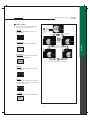
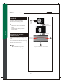
TV Installation and Connection Guide
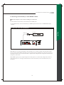
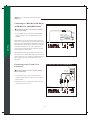
Connecting to a DVD Player with A/V or S Video Cables
Disconnect all power sources before making any connections.
Use this method of connection if your DVD player does not have component (Y, Pb, Pr) jacks.
Note: If your DVD player has component video output connectors, for best picture quality, use the connection
described for Connecting to a DVD Player with Component Connectors. (See page.17)
1.Using an A/V cable, connect the DVD player's Audio OUT jacks to the TV's Audio IN jacks.
2.Using an S-Video Cable, connect the DVD player's S Video OUT jack to the TV's S Video IN jack.
For 242 / 247 / 252 / 255 TFHD Models
DVD Player
A/V cable with
RCA connector
Red
White
Yellow
S Video cable
Note: When you connect video equipment to both the same Video and S-Video input jacks, the display will
automatically select S-Video first.
To view Video signal, please disconnect the S-Video jack or turn off the Video signal on the video equipment.
S-Video is strongly recommended for use if your VCR or video equipment has the option.
S-Video input has better quality of picture than a composite Video signal.
16
English
Rear of TV
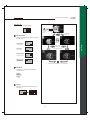
TV Installation and Connection Guide
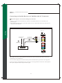
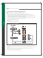
Connecting to a DVD Player with Component Cables
Disconnect all power sources before making any connections.
Use this method of connection if your DVD Player has component (Y, Pb, Pr) jacks.
1.Using a component video cable, connect the DVD Player's Y, Pb and Pr jacks to the Y, Pb and Pr jacks on the
TV.
Colors on Component Video connectors:
Y: Green
Pb (also identified as Cb, CB or B-Y): Blue
Pr (also identified as Cr, CR or R-Y): Red
English
Note: The Y, Pb and Pr jacks on your DVD player are sometimes labeled as Y, Cb and Cr, or B-Y and R-Y.
If so, connect the cables to the matching colors.
2.Using an Audio cable, connect the DVD player's Audio OUT jacks to the TV's Audio in jacks.
For 242 / 247 / 252 / 255 TFHD Models
Rear of TV
Red
Audio cable
White
Red
Component cable
with RCA connector
Blue
Green
DVD Player
Note: The Y, Pb and Pr jacks do not provide audio, so audio cables must be connected to provide sound.
Note: The YPbPr connection provides the best quality of video signal compared to AV (Composite) and
S-Video connection.
Note: YPbPr is set at default to best perform with FHD 1080p content, set Input to "Interlace DVD"
for best performance with regular 480i and 480p content.
(Menu - Picture - Mode - Input = "Interlace DVD")
17
TV Installation and Connection Guide
Connecting to a DVD Player with HDMI Cables
Disconnect all power sources before making any connections.
Use this method of connection if your DVD Player has HDMI jacks.
1.Using a HDMI cable, connect the DVD Player's HDMI output terminal to the TV's HDMI-HDCP input
terminal.
For 242 / 247 / 252 / 255 TFHD Models
English
DVD Player
HDMI cable
Rear of TV
Note: HDCP is a copy protected digital connection that receives analog or digital video and audio signals
from equipment with a HDMI output that features the HDCP function. HDMI allows the transfer of digital
uncompressed data to the TV. This connection is superior when compared to the Component, S Video or AV
(composite) connections.
Note: HDMI signal is purely digital and provides a better picture, it is better than component, S-Video or
Video connections. It is strongly recommended to use this connection if you have this function on your
equipment.
18
TV Installation and Connection Guide
Connecting to a Satellite Receiver or Cable Box with A/V Connectors
Disconnect all power sources before making any connections.
1.Connect a 75-ohm coaxial cable from your Cable TV to the Satellite Receiver's or Cable Box's Ant
(Antenna) jack.
2.Using Audio and S Video cables, connect the satellite receiver's Audio and S-Video OUT jacks to the TV
Audio and S Video IN jacks.
For 242 / 247 / 252 / 255 TFHD Models
English
Rear of TV
Satellite Receiver
or Cable Box
A/V cable with
RCA connector
White
Yellow
2
1
Red
S Video cable
(75-ohm
coaxial cable)
Note: When you connect video equipment to both the same Video and S-Video input jacks, display will
automatically select S Video first.
To view S-Video signal, please disconnect Video jack or turn off the Video signal on the video equipment.
S-Video is strongly recommended for use if your VCR or video equipment has it because S-Video input has
better quality of picture than a composite Video signal.
19
TV Installation and Connection Guide
Connecting to a VCR, PVR, or DV with A/V Cables
Disconnect all power sources before making any connections.
1.Using A/V cable and S-Video cables, connect the video equipment's Audio and S-Video OUT jacks to the
TV's Audio and S-Video In jacks.
For 242 / 247 / 252 / 255 TFHD Models
Rear of TV
A/V cable with
RCA connector
Red
White
Yellow
PVR
S Video cable
DV
Connecting both Video IN and S-Video IN
Note: When you connect video equipment to both the same Video and S-Video input jacks, display will
automatically select S-Video first.
To view Video signal, please disconnect the S-Video jack or turn off the S-Video signal on the video equipment.
S-Video is strongly recommended for use if your VCR or videoeq uipment has it. S-Video input hasa b etter
quality of picture than a composite Video signal.
20
English
VCR
TV Installation and Connection Guide
Connecting to a Blue-Ray DVD Player
or HD-Receiver with HDMI Cables
For 242 / 247 / 252 / 255 TFHD Models
Disconnect all power sources before making
any connections.
1.Using a HDMI cable, connect the DVD's HDMI
output terminal to the TV's HDMI-HDCP input
terminal.
Blue-Ray DVD
Player / HD-Receiver
Rear of TV
Note: HDMI signal is purely digital and provides a
better picture, it is better than component, S-Video or
Video connections. It is strongly recommended to use
this connection if you have this function on your
equipment.
For 242 / 247 / 252 / 255 TFHD Models
Connecting to a PC with VGA
Connector
PC
Disconnect all power sources before making
any connections.
D-sub 15
pin cable
Audio cable
1.Using a D-Sub 15 pin cable, connect the VGA
2.You may need to use a Stereo mini jack to Audio in
connectors to receive audio.
Rear of TV
21
Red
output terminal of the PC to the TV's VGA signal
input terminal.
White
English
Note: HDCP is a copy protected digital connection
that receives analog or digital video and audio signals
from equipment with a HDMI output that features the
HDCP function. HDMI allows the transfer of digital
uncompressed data to the TV. This connection is
superior when compared to the Component, S Video
or AV (composite) connections.
HDMI
cable
TV Installation and Connection Guide
Connecting to a D-VHS with HDMI Cables
Disconnect all power sources before making any connections.
1.Connect a 75-ohm coaxial cable from your cable or antenna to the Set-Top-Box's Antenna jack.
2.Using Audio and S-Video (YPbPr, or HDMI is strongly recommended) cables, connect the Set-Top-Box's
Audio and S-Video OUT jacks to the TV's Audio and S-Video IN jacks.
3.Connect an I-Link cable from the Set-Top-Box to the D-VHS equipment for video transmission and record.
4.Using a HDMI cable, connect the D-VHS's HDMI OUT jack to the TV's HDMI IN jacks for watching the
recorded videos.
For 242 / 247 / 252 / 255 TFHD Models
Cable/Satellite
(75-ohm
coaxial cable)
A/V cable with
RCA connector
2
i-Link
cable
Red
White
Yellow
S Video cable
D-VHS
4
HDMI
cable
Rear of TV
Note: HDCP is a copy protected digital connection that receives analog or digital video and audio signals from
equipment with a HDMI output that features the HDCP function. HDMI allows the transfer of digital
uncompressed data to the TV. This connection is superior when compared to the Component, S Video or AV
(composite) connections.
Note: HDMI signal is purely digital and provides a better picture, it is better than component, S-Video or Video
connections. It is strongly recommended to use this connection if you have this function on your equipment.
22
English
3
Rear of TV
1
Set-Top-Box
TV Installation and Connection Guide
Connecting to a D-VHS with Component Cables
Disconnect all power sources before making any connections.
Use this method of connection if your D-VHS has component (Y, Pb, Pr) jacks.
1.Connect a 75-ohm coaxial cable from your cable or antenna to the Set-Top-Box's Antenna jack.
2.Using Audio and S-Video (YPbPr, or HDMI is strongly recommended) cables, connect the Set-Top-Box's
Audio and S-Video OUT jacks to the TV's Audio and S-Video IN jacks.
3.Connect an I-Link cable from the Set-Top-Box to the D-VHS equipment for video transmission and record.
4.Using Audio and Component video cables, connect the D-VHS's Audio and Y, Pb and Pr OUT jacks to the
TV's Audio and Y, Pb and Pr IN jacks for watching the recorded videos.
English
Colors on Component Video connectors:
Y: Green
Pb (also identified as Cb, CB or B-Y): Blue
Pr (also identified as Cr, CR or R-Y): Red
For 242 / 247 / 252 / 255 TFHD Models
1
Cable/Satellite
Rear of TV
(75-ohm
coaxial
cable)
Set-Top-Box
Red
White
3
i-Link
cable
A/V cable with
RCA connector
Yellow
2
S Video cable
Red
White
D-VHS
Red
Blue
Green
Component cable with RCA connector
4
Audio cable
Note: The Y, Pb and Pr jacks do not provide audio, so audio cables must be connected to provide sound.
Note: The YPbPr connection provides the best quality of video signal compared to AV (Composite) and S-Video
connection.
Note: YPbPr is set at default to best perform with FHD 1080p content, set Input to "Interlace DVD"
for best performance with regular 480i and 480p content.
(Menu - Picture - Mode - Input = "Interlace DVD")
23
TV Installation and Connection Guide
Connecting to an Audio Receiver
Disconnect all power sources before making any connections.
(For Analog Audio Source)
1.Using the R/L audio cable, connect the TV's audio OUT jack to the audio receiver's audio IN or AUX IN jacks.
For 242 / 247 / 252 / 255 TFHD Models
Rear of TV
English
Audio Receiver
White
Audio cable (R/L)
Red
(For Digital Audio Source)
1.Using the Coaxial or Optical audio cable, connect the TV's audio OUT jack to the audio receiver's Coaxial or
Optical IN jacks.
For 242 / 247 / 252 / 255 TFHD Models
Speaker Outputs
Audio Receiver with
the Coaxial or Optical
In / Out Jack
Audio cable (Coaxial or Optical)
Rear of TV
Note: Speakers must be amplified using an audio receiver such as a Home Theater System to amplify the audio
from the TV.
24
TV Installation and Connection Guide
Connecting to a Home Theater System or Earphone Set
Disconnect all power sources before making any connections.
For 242 / 247 / 252 / 255 TFHD Models
Rear of TV
Home Theater System
English
Audio cable
(R/L)
White
Red
Note: When connecting an Audio output signal, an external Audio amplifier is necessary to amplify the signal
for external speakers.
Note: If you connect a Home Theater Sound System, please disable the TV's speakers in the OSD by selecting
off in audio section. Volume adjustment must be made on the Home Theater Receiver. By not disabling the TV's
speakers it may cause the speakers or the TV itself damage.
For 242 / 247 / 252 / 255 TFHD Models
Headphone Set
Rear of TV
Note: When headphone is plugged in the speaker, it will turn into mute mode.
25
TV Installation and Connection Guide
Instruction for Uploading New Firmware
1.Go to our website : www.olevia.com and register your TV.
2.Click FutureProofTM your TV. You will need the serial number of your Olevia TV and a USB flash drive.
3.Click on the instructions for your particular model of Olevia TV.
English
26
Remote Control Guide
Remote Function Keys & Description
SET Press to activate the "Device Programming"
function.
20 HotKeys Press to directly access certain
Shortcut TV functions.
DEVICE BUTTONS Press to select the equipment
item you want to program or operate.
FREEZE Press to freeze the picture. Press again
to unfreeze the picture.
AUTO Press to adjust screen position automatically
when the screen image is not centered under VGA mode.
Other Buttons They only can work when operating
the other equipment such as DVD, or VCR device.
English
1. / REVERSE/FAST FORWARD Press to fast
reverse/forward playback.
2. PLAY Press to begin a Disc play.
3. / SKIP BACKWARD/FORWARD Press to
skip backward/forward the chapter, or track.
4. PAUSE Press to pause a Disc play.
5. Record Press to recordthe chapter, or track.
6. STOP Press to stop a Disc play.
GUIDE Press to see the Channel Guide. (Universal
1. SOURCE Press to switch the source input.
2. C.C. Press to turn on/off the Closed Caption(CC)
function.
3. FAVORITE Press to select favorite channels.
Can be preset in OSD Menu.
4. DISPLAY Press to display the information of
current channel number.
5. SLEEP Press to automatically shut off the TV
after a preset period of time has passed.
6. VIEW Press to select and program Full Screen,
PIP and Split Screen viewing options.
7. SWAP Press to swap the positions of the source
when in PIP or Split Screen modes.
8. ASPECT Press to switch the aspect ratio between
Aspect, Full, Panoramic, Zoom, 1:1 mode.
Device Only)
DIRECTION BUTTONS :
1. / Press to select between four main sections
or select the function item.
2. / Press to enter to Sub-Menu, select the
function item or adjust the value bar.
1
12
2
3
4
INFO Press to see the current program name and
relevant information.
LAST Press to return the previous-channel.
13
14
5
VOL+/ VOL- Press to adjust the volume.
6
NUMBER BUTTONS Press to select channels on
the display.
1. Press to select sub-channel.
2. ENTER Press to confirm the channel number
you enter on TV mode.
7
POWER Press to turn display on/off.
9
-
8
10
LIGHTING Press to switch the lighting mode
between Dark, Medium, Bright Room.
15
16
17
18
19
11
AUDIO Press to switch the TV Audio System
between SAP, Mono or Stereo mode.
EXIT Press to go back last OSD Menu or close
OSD Menu. (Universal Device Only)
ENTER Press to enter to Sub-Menu, or highlight
and set up menu.
20
17 MENU Press to activate or close the On Screen
Display menu.
18 CH + / CH- Press to adjust channel up and channel
down.
19 MUTE Press to mute the sound.
27
Remote Control Guide
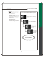
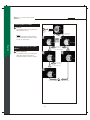
Programming the Remote Control
3
Programming A Device
If you have the other equipment you want to operate with
the TV's remote control, do the following procedures
to program the remote control.
2
1. Select the 5-digit code number for the equipment you
want to operate from the lists on Page 69.
2. Press a device button (for example, DVD, SAT, or TV).
3. Press and hold the "SET" button until the LED indicator
English
blinks twice.
4. Enter the 5-digit code number for your equipment by
using the numeric buttons.
(Note: If there are more than one code on the list, try entering each
code one by one until it is correct for the equipment.)
5. Aiming the TV's remote control at the equipment, such as
STB, DVD, or VCR, and then press its "POWER" button.
(Note: If it responds, the programming is completed. If not, try the
other code again following the steps above.)
Programming A Learned Key
4
This TV's remote control also includes a learning feature,
so you can add functions that are unique to your home
entertainment device, do the following procedures
to program the remote control.
1. Press and hold the "SET" button until the LED indicator
blinks twice.
2. Enter "9 7 5" .
3. Press a device button (for example, DVD, or SAT) to
assign a mode for learning.
4. Press this TV's remote control head-to-head from your
original remote control.
5. On the TV's remote control, press a key where the learned
function will be stored.
6. On the original remote control, press and hold a key to
be learned until the LED indicator on the TV's remote
control blinks twice.
(Note: For the details, please read its User's Guide
carefully.)
28
Notes : The factory default code for this TV
product is 11610. To operate the other TV
device, such as the Olevia LT Series models,
please do the following :
1. To unlock the TV mode, press and hold
the "SET" button until the LED indicator
blinks twice.
2. Enter "982".
3. When the LED indicator blinks 4 times,
enter the 5-digit code number, 11331,
11858, 11240, or 11144.
Remote Control Guide
Battery Installation
1.Push the tab and pull it out as illustrated below.
2.Insert two size AAA batteries (supplied) by matching the (+) and (-) on the batteries
into the remote control's battery department. (Refer to Figure 1)
3.Replace the cover back and make sure the cover "snaps" into the remote control.
(Refer to Figure 2)
(Figure 1)
(Figure 2)
English
1
2
3
AAA
AAA
Note:
1.The display unit comes with two new AAA batteries as accessories.
However, due to uncontrollable causes, the electricity of the accessorized batteries
may be partially or completely drained. We do not warrant the quality of the batteries
in any case since many factors are considered. If replacement is needed, please purchase
two AAA batteries.
2.Handle remote with care. Avoid dropping it, placing in direct sunlight, near a heater,
high areas of humidity or getting it wet. If the remote gets wet, please wipe it dry
immediately. In the event of the remote not working properly or is in operational, a
replacement of remote control may be required.
3.If you do not use the remote control for a long period of time, please remove the batteries
and store in a cool place to preserve battery life.
4.Do not mix new and used or with different types of batteries for operation.
29
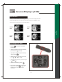
On Screen Displays (OSD)
Introduction
After you have finished connecting your TV, you are now ready to choose
and personalize your TV settings in the OSD (On Screen Display) menu.
There are four main sections in the OSD Menu:
Screen
OSD
Audio
OSD
Setup
OSD
English
Picture
OSD
Operating in the OSD
1. Press "
" button to enter OSD
menu mode.
2. To select between four main sections,
press the keys " " and " ".
3. To enter to Sub-Menu,press the keys
" " ," " or "
".
4. To select the function item, press the
ke ys " ", " ", " ", or " ".
5. To adjust the value bar, press the keys
" " an d " ".
6. To select and set up, press "
".
7. To go back last OSD Menu or exit the
OSD menu, press "
" again or
without action for 12 seconds of
inactivity.
30
OSD
On Screen Displays (OSD)
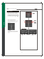
Initial Screen
1.
1. Selecting the OSD Language
(To select
the item)
The first time you power on the TV, there
are three language formats available for
the OSD Menu. You may select it by doing
~
the following: English, Francais, Espanol.
2. Selecting Input Source
2.
English
After the Language selection, the Input
Source Screen will appear for your
selection.
(To select
the item)
(To confirm)
2.1 Tuner Source
2.1 Tuner1 :
By selecting Tuner1 you must perform
a channel scan by following the menu
screens.
(To select (To confirm)
the item)
31
(To select (To confirm)
the item)
OSD-Picture
On Screen Displays (OSD)
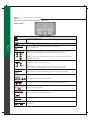
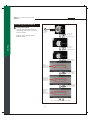
Picture OSD Adjusting TV Picture Settings
Description of Settings
Power Up
Idea
Off
White Peak Limiter
Adjustment
Function
To adjust brightness contrast of the picture
To adjust color contrast of the picture
To adjust image color intensity
Low, Medium, High, Off
To select the nature color tones of the picture
To adjust the color intensity
To decrease or increase red or green tones of the picture
To adjust sharpness or softness of the picture
To reduce high frequency noise signal
Dark, Medium, Bright Room To adjust darkness or lightness of the screen
VCR, Interlaced DVD,
To select the video input source with varied qualities
Progressive DVD, Standard
Def TV, High Def TV, User
Showroom, Home
To select the varied place where you operate this device
To limit the signal amplitude varying degree resulted in
brightness over saturation
To extend "gray" to "black" color for a more accurate
picture
To enhance the contrast of the picture
Black Level Extender
Contrast Enhance
Note : Your TV performs best at a Color Temperature of 6500. Follow the Four Steps to
properly set your display Color Temperature to 6500.
Step 1. Press Menu
Step 2. Press Up/Down until you see
PICTURE, then press enter
Step 3. Press Up/Down until you see
Color Temp, then press enter
Step 4. Press Up/Down until you
see 6500, then press enter
32
English
Item
Brightness
Contrast
Color temp
6500
Native
Color
Tint
Sharpness
Noise Reduction
Mode
Lighting
Input
OSD-Picture
On Screen Displays (OSD)
Selecting the Picture Mode
Mode
In this " Mode" Index, you can select one
of the picture modes which is suitable for
the program you are watching.
(To show
the Main
Menu)
(To select
the item)
(To enter the
sub-menu)
(To select the item)
Lighting :
To adjust darkness or lightness of the
screen
* Dark Room : To darken the screen
English
(To enter the
sub-menu)
* Medium Room
* Bright Room : To brighten the screen
(To select
the item)
Input :
To select the video input source with
varied qualities
(To enter the
sub-menu)
(To select
the item)
* VCR
* Interlaced DVD
* Progressive DVD
* Standard Def TV
(To go back last OSD Menu or exit OSD Menu)
* High Def TV
* User
33
OSD-Picture
Power Up :
Selects the most appropriate setting
for your TV. (Read carefully, modes
effect TV performance.)
On Screen Displays (OSD)
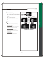
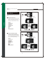
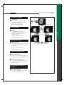
Disable Showroom Mode and Enable Home Mode
(Follow these 4 steps to activate Home Mode)
* Showroom (Demo) :
This mode is available for businesses
that will use the TV to demonstrate in
their stores. (Notes : This mode blocks
Step 1. Press Menu and Scroll up/down
to "Picture" and press the "Enter or Right
Arrow key".
most OSD settings.)
* Home (Normal Use) :
This mode provides the best settings
to view the TV for regular use.
Step 3. Scroll up/down
to "Power Up" and
press "Enter or Right
Arrow key".
Step 4. Scroll up/
down to "Home"
and press "Enter
or Right Arrow
key" to activate
HOME MODE.
Congratulations!
You are in Home Mode.
34
English
Step 2. Scroll up/down to "Mode"
and press "Enter or Right Arrow
key".
OSD-Picture
On Screen Displays (OSD)
Adjusting the Video or
Picture Quality
In this Setup Index, you can adjust the video
and picture settings to suit your personal
preferences.
(To show
the Main
Menu)
(To select
the item)
(To enter the
sub-menu)
Brightness
To darken or brighten the picture
Contrast
(To select
the item)
To reduce(soften) or enhance(deepen)
color contrast of the picture
English
(To enter the
sub-menu)
(To adjust the settings)
Color
To decrease or increase color intensity
of the picture
Tint
(To go back last OSD Menu or exit OSD Menu)
It allows you to decrease or increase red
or green tones of the picture.
Sharpness
To soften or sharpen the picture
Color Temp
To customize the RGB settings
(To show
the Main
Menu)
(To select
the item)
(To enter the sub-menu)
6500 (recommended)
(To select the item)
Native :
To select the nature color tones of the
picture
(To enter the
sub-menu)
(To select
the item)
(To go back last OSD Menu or exit OSD Menu)
35
OSD-Picture
On Screen Displays (OSD)
Noise Reduction
Select Low/Medium/High to reduce noise.
Low : To reduce parts of noise(recommended)
Medium : To reduce half of noise
(To show
the Main
Menu)
(To select
the item)
(To enter the
sub-menu)
High : To reduce most of noise
Off : Dynamic Noise Reduction is disable.
(To select
the item)
(To enter the
sub-menu)
(To select
the item)
Off :
To disable this function(recommended)
White Peak Limiter :
Limits the signal amplitude varying degree
resulted in brightness over saturation.
Black Level Extender :
Extends "grays" to black so a more
accurate picture is produced with a wider
contrast scale.
(To go back last OSD Menu or exit OSD Menu)
Contrast Enhance :
Enhances the contrast of the picture.
36
English
Idea
OSD-Audio
On Screen Displays (OSD)
Audio OSD Adjusting Sound Quality
Description of Settings
Item
Treble
Bass
Balance
Language
MTS (Multi-channel
Television Sound)
Mute
Speaker
English
iDIVA
Lip Sync
Adjustment
Function
It allows to adjust higher pitched sounds.
It allows to adjust lower pitched sounds.
It allows to adjust volume balance of the R/L speakers for
the best stereo reproduction.
English, Francais, Espanol
There are three language formats available for program
broadcasting.
Mono, SAP, Stereo
It allows to select the sound reception of stereo, bilingual
and mono programs between the TV Audio System.
On, Off
It allows to mute the sound.
On, Off
It allows to turn On/Off the speakers of the TV when using
a Receiver or Home Theater System.
Off, Rock, POP, Live, Classic, It allows to select the sound effect as occurred in an
Soft, Concert, Living Room,
enclosed space of varying spaces.
Hall, Arena, Church
It allows to properly synchronize the audio and video.
Adjusting the Audio Settings
In this Setup Index, you can adjust the audio
settings to suit your personal preferences.
Treble
(To show
the Main
Menu)
(To select
the item)
(To enter the
sub-menu)
Decreases/Increases high pitch sounds.
Bass
Decreases/Increases low pitch sounds.
(To select
the item)
Balance
Adjusts volume to R/L speakers for the
best stereo reproduction.
(To enter the
sub-menu)
(To adjust
the settings)
Language
(To select
the item)
There are three language formats
available for program broadcasting. You
may select from: English, Espanol,
Francais. (Digital TV Channel Only)
Mute
Mutes sounds.
(To go back last OSD Menu or exit OSD Menu)
Speaker
Turns TV speakers On/Off when using
Home Theater System.
37
OSD-Audio
On Screen Displays (OSD)
iDIVA
It allows to select the sound effect as
occurred in an enclosed space of varying
spaces.
Off : To disable this function
(To show
the Main
Menu)
(To select
the item)
(To enter the
sub-menu)
Rock :
POP :
Audio
Audio
Live :
Classic :
Lip Sync
Soft :
Concert :
Living Room :
iDIVA
(To select
the item)
(To adjust
the settings)
Arena :
Church :
English
(To enter the
sub-menu)
Hall :
(To select
the item)
iDIVA
Lip Sysc
Lip Sync
Living Room
When the sound and picture do not match
and the sound is heard too early, use this
setting to properly synchronize the audio
and video.
(To go back last OSD Menu or exit OSD Menu)
MTS System for Stereo TV
In this Setup Index, you can adjust the audio
settings to suit your personal preferences.
MTS
(To show
the Main
Menu)
(To select
the item)
(To enter the
sub-menu)
Toggles audio through Stereo, SAP and
Mono.
(To select the item)
Mono :
Selects Mono reception. (Uses to
reduce noise during weak stereo
broadcasts)
(To enter the
sub-menu)
SAP :
Selects audio to Secondary Analog
Program. (If no SAP signal is present,
the TV remains in Stereo Mode)
(To select
the item)
Stereo :
Selects Stereo reception when viewing
a program.
(To go back last OSD Menu or exit OSD Menu)
38
OSD-Screen
On Screen Displays (OSD)
Screen OSD Adjusting Screen Modes
Description of Settings
Item
Adjustment
H.Position
V.Position
Fine Tune
Auto Sync
Aspect Ratio
Cropping
View
PIP Position
Adjustment
Function
It allows you to adjust the picture position horizontally.
It allows you to adjust the picture position vertically.
It allows you to enhance the picture quality.
English
Aspect, Full Screen,
Panoramic, Zoom 1,
Zoom 2, 1:1 Mode
On, Off (Off, Minimum,
Medium, Maximum)
Full Screen, PIP, Split Screen
Low Right, Low Left,
Upper Right, Upper Left
Small, Medium, Large
PIP Size
Swap
Main Picture Source Tuner1, Composite1/2,
S-Video1/2, Component1/2,
HDMI1/2, VGA, VGAComponent
Sub Picture Source Tuner1, Composite1/2,
S-Video1/2, Component1/2,
HDMI1/2, VGA, VGAComponent
It allows you to select the aspect ratio of the picture you
are watching.
Crops image and then enlarges it to fill the screen.
It allows you to select the view types of picture modes.
It allows you to change the position of Picture 2.
It allows you to change the size of Picture 2.
It allows you to switch the position of Picture1 and Picture2.
It allows you to select the main picture or video source
you want to view.
It allows you to select secondary picture or video source
you want to view.
Changing the Screen Mode
In this Setup Index, you can adjust the screen
settings to suit your personal preferences.
Adjustment (Analog Source Only)
(To show
the Main
Menu)
(To select
the item)
(To enter the
sub-menu)
Adjusts the picture position and its
quality.
(To select the item)
H.Position :
Moves the picture left and right in the
"Full Screen, Panoramic, and Zoom"
modes.
V.Position :
Moves the picture up and down in the
"Full Screen, Panoramic, and Zoom"
modes.
(To enter the
sub-menu)
Fine Tune :
Enhances picture quality by reducing
horizontal flickering.
(To select
the item)
(To enter the
sub-menu)
Auto Sync :
Adjust the image to its best position and
automatically displays on the screen.
(To adjust the settings)
(VGA mode only)
(To go back last OSD Menu or exit OSD Menu)
39
OSD-Screen
On Screen Displays (OSD)
Aspect Ratio
It allows you to select the aspect ratio
of the picture you are watching.
Aspect :
Toggles picture between 16:9 / 4:3
aspect ratio.
(To show
the Main
Menu)
(To select
the item)
(To enter the
sub-menu)
(To select
the item)
(To enter the
sub-menu)
(To select the item)
Panoramic :
Enlarges a picture from 4:3 to 16:9 by
stretching it horizontally.
(To go back last OSD Menu or exit OSD Menu)
Zoom 1 :
Stretches the image both horizontally
and vertically.
1
Zoom 2 :
Stretches the image both horizontally
and vertically, which will lose part of the
image on both ends.
2
1:1 Mode :
Returns the image to its original mode.
1:1
40
English
Full Screen :
Enlarges a 4:3 picture to fill the 16:9
screen.
OSD-Screen
On Screen Displays (OSD)
Cropping Method 1
Crops 16 pixels on R/L edge of image,8
lines on top/bottom edge of image, and
then enlarges it to fill the screen.
(For all sources except Tuner source)
(To select
the item)
(To show
the Main
Menu)
On : (recommended)
Off :
(To enter the
sub-menu)
Cropping Method 2
Screen
Crops image, and then enlarges it to fill
the screen. (Tuner Source Only)
View (To select
Off :
the item)
English
Minimum : To crop 16 pixels on the R/L
edge of image, 8 lines on the top/bottom
edge of image(recommended)
(To enter the
sub-menu)
(To select the item)
Medium : To crop 24 pixels on the R/L
edge of image, 16 lines on the top/bottom
edge of image
View
PIP
Maximum : To crop 32 pixels on the R/L
edge of image, 24 lines on the top/bottom
edge of image
(Note: This feature helps remove any noise visible
under both vertical and horizontal edges of the
image.)
(To go back last OSD Menu or exit OSD Menu)
View
You can select three view types of picture
modes that best suits the program you
are watching. You can set a different view
mode for each video mode for each input
and store it manually.
Full Screen :
Enlarges the image to full the screen.
Pic1
PIP :
Picture-in-Picture has a Main screen and
small screen view.
Connected to two input sources. PIP is
available on selected models.
Pic1
Pic2
41
OSD-Screen
On Screen Displays (OSD)
Split Screen :
Full Screen splits in two Views.
Pic1
Pic2
(To show
the Main
Menu)
(To select
the item)
(To enter the
sub-menu)
PIP Position
Screen
Changes the position of Picture 2 (small
screen view).
Low Right :
PIP Position
(To select
the item)
Pic1
Pic2
English
(To enter the
sub-menu)
(To select the item)
Pic1
Low Left :
Pic2
PIP Size
Pic2
Upper Right :
Medium
Pic1
Upper Left :
PIP Position
Pic2
Pic1
(To go back last OSD Menu or exit OSD Menu)
PIP Size
Changes the size of Picture 2 (small
screen view).
Small :
Medium :
Large :
Swap
Switches the position of Picture 1 and
Picture 2.
Pic1
Pic2
Pic2
Pic1
42
Low Right
OSD-Screen
On Screen Displays (OSD)
Selecting the Picture or
Video Source
In this Setup Index, you can select the input
source of the picture or video you want to
view.
(To show
the Main
Menu)
(To select
the item)
(To enter the
sub-menu)
Main Picture Source
(To select the item)
It allows you to select and view the main
picture or video source from optional video
equipment connected to this unit by
selecting the appropriate input source.
Tuner 1 :
English
(To enter the
sub-menu)
Composite 1/2 :
S-Video 1/2 :
Component 1/2 :
HDMI 1/2 :
(To select
the item)
VGA :
VGA-Component :
(To go back last OSD Menu or exit OSD Menu)
Sub Picture Source (PIP)
It allows you to select and view the
secondary picture or video source from
optional video equipment connected to
this unit by selecting the appropriate input
source. (In PIP and Split Mode Only)
(To show
the Main
Menu)
(To select
the item)
(To enter the
sub-menu)
(To select the item)
Tuner 1 :
Screen
Composite 1/2 :
S-Video 1/2 :
Sub Picture Source
Component 1/2 :
HDMI 1/2 :
(To enter the
sub-menu)
VGA :
Sub Picture Source
VGA-Component :
Component 1
(To select
the item)
(To go back last OSD Menu or exit OSD Menu)
43
OSD-Setup
On Screen Displays (OSD)
Setup OSD Adjusting Personal TV Settings
Description of Settings
Item
TV
Channel Setup
Auto Channel Search
Channel Add
Closed Caption
Analog Type
Digital Type
Font
Size
Background Color
Parental Control
Enter Password
Rating
MPAA Rating
Block Unrating
TV Rating
Function
Favorite, Skip, Name
Cable Standard, Air
It allows you to set up Channel functions.
It can auto scan the available channels of the TV or CATV.
It allows you to add channels to your favorite channel list.
It allows you to select the Closed Caption type shown on
the TV program.
CC1~4, T1~4
Off, CS1~6
As Broadcaster, Stype1~7
As Broadcaster, Large,
Medium, Small
Black, White, Green, Blue,
Red, Cyan, Yellow, Magenta
Black, White, Green, Blue,
Red, Cyan, Yellow, Magenta
On, Off
G, PG, PG-13, R/NC-17, X
On, Off
TV-Y, TV-Y7, TV-Y7-FV
TV-G, TV-PG(V,S,L,D),
TV-14(V,S,L,D), TV-MA
(V,S,L)
Canada English Rating
Canada French Rating
Channel Block
Change Password
Timers
Sleep
Date and Time
Menu Timeout
10, 20, 30
Language
DPMS
~
English, Francais, Espanol
On, Off
LED Settings
On, Off
Factory Settings
Factory Settings by Input
Firmware Version
English
Font Color
Adjustment
It can be set to turn on / off the TV automatically at the set
time.
It allows you to set the information of "Date and Time".
It can be set to shut off the TV automatically after a preset
period of time has passed.
It allows you to set the OSD Menu language.
TV and Backlight will shut off automatically when no video
source is detected when DPMS is active.
It can be set to turn on / off the LED Light on the front
panel of the TV.
It can reset all parameters in OSD Menu Mode for all input
sources.
It can reset all parameters in OSD Menu Mode for the
source yo u select currently.
You can see the firmware version here that installed in the
HDTV unit.
44
OSD-Setup
On Screen Displays (OSD)
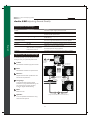
Searching the TV Channels
In this Setup Index, you can pre-search all
channels before watching the programs.
Auto Channel Search
(To show
the Main
Menu)
(To select
the item)
(To enter the
sub-menu)
Will scan and preset all receivable
channels automatically.
(To select the item)
Cable :
Selects cable if using tuner as the input.
English
*
*
*
*
Auto
Standard
HRC
IRC
(To enter the
sub-menu)
(To select the item)
Air :
Selects air if using antenna.
(NOTE: The Auto Scan is set to scan cable TV
channels by default. You cannot receive and
set the cable TV channels and VHF/ UHF
channels at the same time.)
(To enter the
sub-menu)
(To select the item)
(To enter the
sub-menu)
(To select the item)
(To enter the
sub-menu)
(To go back last OSD Menu or exit OSD Menu)
45
OSD-Setup
On Screen Displays (OSD)
Editing Channels
In this Setup Index, you can edit channels to
suit your personal preferences.
Channel Setup
Will scan and preset all receivable
channels automatically.
(To show
the Main
Menu)
(To select
the item)
(To enter the
sub-menu)
(To select the item)
Favorite :
Selects and stores a list of favorite
channels.
(To select the item)
(To enter the
sub-menu)
(To select the item)
(To enter the
sub-menu)
(To select
the channel)
(To set up)
(To go back last OSD Menu or exit OSD Menu)
46
English
(To enter the
sub-menu)
Browses through favorite channels by
pressing Hotkey "FAVORITE".
OSD-Setup
On Screen Displays (OSD)
Skip :
Skips channels from viewing.
(NOTE: Once this function is set, the skipped
channels will not be displayed after searching.
If you wish to view later, enter the channel
number by pressing the numeric keys on the
remote control.)
(To show
the Main
Menu)
(To select
the item)
(To enter the
sub-menu)
(To select the item)
English
(To enter the
sub-menu)
(To select the item)
(To enter the
sub-menu)
(To select the item)
(To enter the
sub-menu)
(To select
the channel)
(To set up)
(To go back last OSD Menu or exit OSD Menu)
47
OSD-Setup
On Screen Displays (OSD)
Name :
Creates a personal name for each channel.
(Analog TV Channel Only)
Name will appear in the upper-right corner
of the screen.
(To show
the Main
Menu)
(To select
the item)
(To enter the
sub-menu)
(To select the item)
(To select the item)
(To enter the
sub-menu)
(To select the item)
(To select
the item)
(To enter the
sub-menu)
(To set up)
Shift
(To enter
the submenu)
(To enter
the submenu)
(To select
the channel)
(To go back last OSD Menu or exit OSD Menu)
48
English
(To enter the
sub-menu)
OSD-Setup
On Screen Displays (OSD)
Channel Add :
Adds channel currently on display to
the FAVORITE channel list.
(To show
the Main
Menu)
(To select
the item)
(To enter the
sub-menu)
(To select the item)
English
(To enter the
sub-menu)
(To select the item)
(To enter the
sub-menu)
(To select the item)
(Key in channel
number by
pressing the
numeric key )
Enter
(To go back last OSD Menu or exit OSD Menu)
49
OSD-Setup
On Screen Displays (OSD)
Closed Caption Options
Displays the audio portion of a television
signal as text on the television screen.
Analog Type
(To show
the Main
Menu)
(To select
the item)
(To enter the
sub-menu)
If there is Closed Caption data shown on
the analog TV channel, you can select
your preferred Closed Caption type by
scrolling through CC1~4, T1~4.
(To select the item)
(To enter the
sub-menu)
Digital Type
(To select
the item)
Selects preferred Close Caption type by
scrolling through CS1 - 6.
(To enter the
sub-menu)
Font
(To select the item)
Selects preferred font by scrolling
through As Broadcaster, Style 1-7.
???
(Digital TV Channel Only)
Size
Selects preferred font size by scrolling
through As Broadcaster, Large, Medium,
Small. (Digital TV Channel Only)
(To go back last OSD Menu or exit OSD Menu)
Font Color
Selects preferred font color by scrolling
through As Broadcaster, Black, White,
Green, Blue, Red, Cyan, Yellow,
Magenta. (Digital TV Channel Only)
Background Color
Selects preferred background color by
scrolling through As Broadcaster, Black,
White, Green, Blue, Red, Cyan, Yellow,
Magenta. (Digital TV Channel Only)
50
English
CC1 : is used for most programs
CC2 : may be used for alternate languages
Text : is used for network and station
information, such as channel guides,
schedules, or bulletin board, for Closed
Caption programs.
OSD-Setup
On Screen Displays (OSD)
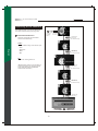
Setting up Parental Control
Password
This function allows programs to be
restricted and controlled by parents.
(To show
the Main
Menu)
Enter Password
(To select
the item)
(To enter the
sub-menu)
Password is necessary to enter and
re-enter the Parental Control Menu
screen.
(To select the item)
(NOTE: The Factory Default password is
999999 or 314159)
English
(To enter the
sub-menu)
Activating the Parental
Control Feature
Blocks programs based on programing rating
system.
(Key in
password by
pressing the
numeric key )
(To confirm)
The TV Parental Control features by receiving
the rating signal from your local broadcasting
station or cable service provider.
Rating
* On- To activate rating function
* Off- To disable all of rating functions
(To go back last OSD Menu or exit OSD Menu)
51
OSD-Setup
On Screen Displays (OSD)
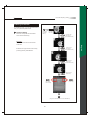
MPAA Rating
Motion Picture Association of America
provide movie ratings, including those
shown on TV.
G : (General Audience) No restriction.
(To show
the Main
Menu)
(To select
the item)
(To enter the
sub-menu)
PG : (Parental guidance suggestion)
Children under 13 should be accompanied
by an adult.
(To select the item)
PG-13 : (Parents strongly cautioned)
Children under 13 should be accompanied
by an adult.
(To enter the
sub-menu)
(To select the item)
NC-17 : (Not classified) Viewers should
be 17 or older.
X : (Adults only)
(To enter the
sub-menu)
USA-Movies
(To select
the item)
(To set up)
(To go back last OSD Menu or exit OSD Menu)
52
English
R : (Restricted) Viewers should be 17 or
older.
OSD-Setup
On Screen Displays (OSD)
TV Rating
U.S. TV ratings are for TV programs
rated according to the U.S. Television
Parental Guidelines.
TV-MA/V/S/L : (Mature audiences only)
(To select
the item)
(To show
the Main
Menu)
(To enter the
sub-menu)
TV-14/V/S/L/D : (Parents strongly
cautioned)
(To select the item)
TV-PG/V/S/L/D : (Parental guidance
suggested)
English
(To enter the
sub-menu)
TV-G : (General audience)
(To select the item)
TV-Y7/FV : (Directed to children under
7 or older)
TV-Y : (All children)
(To enter the
sub-menu)
(NOTE: When you block the lower rating, the
higher age-based ratings are blocked
automatically.)
Block Unrating
You may select "On" for MPAA Unrated
and TV Unrating. This allows you to
block programs or movies that are
broadcast without a rating.
(To select
the item)
(To set up)
To watch unrated channels, re-activate
MPAA Unrated and TV Unrating to "Off".
(NOTE: The unrated option is available only
when you have selected U.S.A. as your
country/ region.)
(To go back last OSD Menu or exit OSD Menu)
53
OSD-Setup
On Screen Displays (OSD)
Canada English Rating
It is available for TV programs in English
broadcast in Canada.
E:
C : (Intended for children under 8)
(To show
the Main
Menu)
(To select
the item)
(To enter the
sub-menu)
C8+ : (Generally considered acceptable
for children aged 8 and older to watch
on their own)
(To select the item)
G : (General Audience)
(To enter the
sub-menu)
14+ : (Not suitable for viewers under
the age of 14)
(To select the item)
18+ : (Adult)
(NOTE: When you block the lower rating, the
higher age-based ratings are blocked
automatically.)
(To enter the
sub-menu)
(To select
the item)
(To set up)
(To go back last OSD Menu or exit OSD Menu)
54
English
PG : (Parental Guidance) Parents may
consider some content inappropriate
for unsupervised viewing by children
aged 8-13.
OSD-Setup
On Screen Displays (OSD)
Canada French Rating
It is available for TV programs in French
broadcast in Canada.
E:
G : (General Audience)
(To show
the Main
Menu)
(To select
the item)
8 ans+: (8+ General--Not recommended
for young children under the age of 8)
(To enter the
sub-menu)
(To select the item)
13 ans+ : (Not suitable for children
under the age of 13)
16 ans+ : (Not suitable for children
under the age of 16)
English
18 ans+ : (Restricted to adults)
(To enter the
sub-menu)
(To select the item)
(To enter the
sub-menu)
(To select
the item)
(To set up)
(To go back last OSD Menu or exit OSD Menu)
55
OSD-Setup
On Screen Displays (OSD)
Channel Block
In this Setup Index, you may select the
blocked ratings to suit your personal
preferences.
(To show
the Main
Menu)
(To select
the item)
(To enter the
sub-menu)
(To select the item)
(To select the item)
(To enter the
sub-menu)
(To select
the channel)
(To set up)
(To go back last OSD Menu or exit OSD Menu)
56
English
(To enter the
sub-menu)
OSD-Setup
On Screen Displays (OSD)
Resetting the Password
Change Password
You may change to a new preferred
password by pressing the numeric key
within 6 numbers.
(To show
the Main
Menu)
(To select
the item)
(To enter the
sub-menu)
(NOTE: The Factory Default password is
999999 or 314159)
(To select the item)
English
(To enter the
sub-menu)
(To select the item)
(To enter "Enter
Password" screen)
(Key in
password by
pressing the
numeric key )
(To confirm and then
enter "Enter New
Password" screen)
(Key in new
password by
pressing the
numeric key )
(To confirm and then
enter "Confirm New
Password" screen)
(Key in new
password
again by
pressing the
numeric key )
(To go back last OSD Menu or exit OSD Menu)
57
OSD-Setup
On Screen Displays (OSD)
Setting the Date and Time
Date and Time
In this Setup Index, you can setup the
Date, Week, Time Zone, and Current
Time on the TV.
(To show
the Main
Menu)
(To select
the item)
(To enter the
sub-menu)
Date :
Date is set automatically when NTSC
source is used. (Manual adjustment is
necessary however, if not used)
(To select the item)
(To enter the
sub-menu)
Time Zone :
You can select available time zone
where you live.
Current Time :
Time is set automatically when NTSC
source is used. (Manual adjustment is
necessary however, if not used)
(To select
the item)
Daylight Savings :
Option will be selected automatically
based on settings above.
Auto Calibration :
Once activating this function, the
information of "Date and Time" will be
corrected automatically based on
accurate time.
(To enter the sub-menu)
(To select
the item)
(To select
the item)
(To confirm)
(NOTE: Once marking the "Auto Calibration"
setting, all settings shown on the "Date and
Time" screen will be invalid.)
(To cycle
selecting)
(To confirm)
(To go back last OSD Menu or exit OSD Menu)
58
English
Day of Week :
It will be automatically displayed
according to the Date setting.
OSD-Setup
On Screen Displays (OSD)
Setting the TV Timer
Timers
In this Setup Index, you can setup the
Sleep Time on the TV.
(To show
the Main
Menu)
(To select
the item)
(To enter the
sub-menu)
Sleep :
Shuts off TV after a preset period of
time has passed by scrolling through
30, 60, 90, 120 minutes.
(To select
the item)
English
Timeout Settings for OSD
Menu
(To enter the
sub-menu)
(To select the item)
Menu Timeout
In this Setup Index, you can setup the
OSD Menu display time before
disappeared when no action is taken.
(To enter the
sub-menu)
(To select the item)
(To go back last OSD Menu or exit OSD Menu)
59
OSD-Setup
On Screen Displays (OSD)
TV OSD Languages
Languages
There are three language formats
available for the OSD Menu. You may
select it doing the following:
~
English, Francais, Espanol.
(To show
the Main
Menu)
(To select
the item)
(To enter the
sub-menu)
Setting DPMS
DPMS
(To select
the item)
(To enter the
sub-menu)
(To select the item)
(VGA Source Only)
* On- To activate this function
* Off- To disable this function
Setting LED Light
LED Settings
(To go back last OSD Menu or exit OSD Menu)
It can be set to turn on / off the LED Light
on the front panel of the TV when shutting
off the TV.
* On- To activate this function
* Off- To disable this function
Factory Default Option
Factory Settings
You can reset all OSD settings to original
manufacture settings for all input sources.
Factory Settings by Input
You can reset all OSD settings to original
manufacture settings for the source you
select currently.
Displaying the Firmware
Version
Firmware Version
You can see the firmware version here
that installed in the HDTV unit.
60
English
TV and Backlight will shut off
automatically when no video source
is detected when DPMS is active.
Specifications
TFT LCD Panel
Specifications
Panel Size
42"
47"
52"
55"
Aspect Ratio
16:9
16:9
16:9
16:9
1920 X 1080
1920 X 1080
1920 X 1080
1920 X 1080
Pixels
Dynamic Contrast Ratio
H/V(View Angle)
Gray to Gray Response
1600:1
1000:1
1600:1
1500:1
176 o(H) / 176o(V)
178 o(H) / 178o(V)
176 o(H) / 176o(V)
176 o(H) / 176o(V)
6.5 ms
8 ms
6.5 ms
10 ms
Time
Video/Graphic Processing
30~85 KHz(H) / 50~80Hz(V) Max. 1920x1080 @60Hz
PC Compatible Frequency
English
Video Compatibility
NTSC / ATSC
480i, 480p, 720p, 1080i, 1080p
DTV & HDTV Compatibility
Aspect Ratio Adjustment
1:1, Aspect, Full Screen, Panoramic, Zoom 1, Zoom 2
3D Comb Filter
Y
3 2 / 2 : 2 Pull Down
Y
Digital Noise Reduction
Y
Adjustable Color
Native, 6500
Temperature
De-interlacer
Y
VGA Auto Frequency
Y
Correction
TV Auto Frequency
Y
Detection
Audio Processing
Auto Sound Level Control
Output Watt
Y
2 (15W + 15W)
2 (20W + 20W)
Sound Effect
2 (25W + 25W)
MTS (Mono / Stereo / SAP)
Input Terminals
TV Tuner
Video Input
HDTV & VIDEO Input
Service Port
Combo RF (NTSC/ ATSC) Tuner x1
Composite x2, S-Video x2, Y/Pb/Pr, Y/Cb/Cr x2, R/L x6
VGA/Component3 x1, HDMI x2, R/L x4
RS232C Port (D-sub 9 Pins) x1, Firmware Upgrade Port (B Type) x1
Output Terminals
Audio Output
Coaxial & Optical x1, R/L x1, SubWoofer x1, Earphone x1
* NOTE : Product Specification is Subject to Change without Notice.
61
2 (25W + 25W)
Specifications
TFT LCD Panel
42"
47"
52"
55"
100~240 VAC / 50-60 Hz
100~240 VAC / 50-60 Hz
100~240 VAC / 50-60 Hz
100~240 VAC / 50-60 Hz
(Power Consumption)
271W
280W
325W
385W
Stand-by
< 1W
< 1W
< 1W
Others
Power (Voltage)
Dimensions (W x D x H)
< 1W
40.98 in x 11.42 in x 29.84 in 45.38 in x 11.42 in x 31.93 in 51.02 in x 12.8 in x 33.76 in
52.32 in x 16.74 in x 34.49 in
Carton Dimensions (W x D x H) 44.48 in x 12.87 in x 33.07 in 51.18 in x 14.57 in x 35.43 in 55.12 in x 14.88 in x 37.00 in 56.42 in x 20.39 in x 39.17in
Weight w/o stand
52.92 Ibs
71.66 Ibs
110.25 Ibs
144.43 Ibs
Weight w/ stand
59.50 Ibs
87.0975 Ibs
132.3 Ibs
187.425 Ibs
Gross Weight
72.77 Ibs
102.53 Ibs
152.15 Ibs
220.50 Ibs
English
Dimensional Drawing
F
E
A
C
B
Size
Model
A
D
B
C
D
E
F
42"
28.50 in
40.98 in
25.94 in
11.42 in
29.84 in
4.72 in
47"
30.99 in
45.38 in
25.17 in
11.42 in
31.93 in
5.52 in
52"
32.30 in
51.02 in
27.40 in
12.80 in
33.76 in
5.65 in
55"
33.11 in
52.31 in
35.43 in
16.73 in
34.49 in
6.63 in
62
Timing Mode for VGA and HDMI(PC)
Source
Resolution
Vertical frequency (Hz)
YPbPr
480p
59.94
720p
60
1080i
30
1080p
60
640x480
60
VGA
75
800 x 600
60
75
1024 x 768
60
English
75
HDMI(PC)
1280 x 768
60
1360 x 768
60
1920 x 1080
60
640 x 480
60
75
800 x 600
60
1024 x 768
60
75
1280 x 720
60
1280 x 768
60
1360 x 768
60
1920 x 1080
60
63
Pixels Policy
SyntaxBrillian's D.O.A. Policy for LCD HDTVs for
Defective Pixels on LCD Panels
(Applicable to the LCD HDTV sold within USA & Canada only)
Customers are required to check their LCD panel immediately after purchase.
To identify defective pixels, the LCD panel should be examined under normal
operating conditions as mentioned above, preferably in its native display
resolution, and with a 90 degrees viewing angle.
A LCD HDTV will be considered dead on arrival (D.O.A.) with regards to defective
pixels on the LCD panel when any one of the following criteria is met:
A total of 7 defective pixels including both bright dots and dark dots are
present (the typical 30" LCD Television screen has 1 million pixels), or
2 or more pairs of adjacent bright dots are present, or
3 adjacent bright dots are present, or
3 adjacent dark dots are present.
In view of customers' concerns about dead pixels, SyntaxBrillian would like to address
that defective pixels are not ultimately avoidable with the current LCD industry
standard panel manufacturing processes. We always strive to improve our
technology and minimize the chance of occurrence of defective pixels by
applying strict screening processes in our factory production processes.
However, SyntaxBrillian cannot guarantee that a return unit to our customers will be
100% free of defective pixels.
For questions, please call our toll free service number in the USA at 888-Syntax-Brillian-8.
"At Syntax-Brillian Corporation, a satisfied customer is our
most important focus."
64
English
SyntaxBrillian LCD HDTVs are evaluated at a distance of approximately 50 centimeters
(approximately 20 inches) between the LCD panel and the eyes of the user at a
90 degrees viewing angle. All LCD panels have been tested to ensure they
comply with our factory standards. Our evaluation is based on the number of
defective pixels and the distance between any two defective pixels. Bright dots
are dots that appear bright and unchanged in size when a LCD HDTV screen
displays under a black pattern; dark dots are dots that appear dark and
unchanged in size when a LCD HDTV screen is displayed under pure red, green,
or blue patterns ("defective pixels"). Adjacent dots are dots located directly
next to each other.
Glossary
3:2 pull down - Process of converting 24 frames per second film to video by repeating one film frame
as three fields, then the next film frame as two fields.
1
1
1
2
2
1
1
1
2
2
480I - 480 lines of display every 1/60 of a second; image is displayed by interlace scanning. See
also Interlaced
480P - 480 lines of display every 1/60 of a second; image is displayed by progressive scanning. See
also Progressive.
720P - 720 lines of display every 1/60 of a second; image is displayed by progressive scanning. See
also Progressive.
1080I - 540 lines of display x 2 every 1/30 of a second; image is displayed by interlace scanning.
See also Interlaced
English
16:9 - Aspect ratio under Hi Def. and theater movie formats. Also known as widescreen; see Aspect
Ratio
4:3 - Aspect ratio under SDTV; see Aspect Ratio
Active Matrix TFT (Thin Film Transfer) - A type of display technology where the three primary
colors are modulated. Results in better contrast ratios suitable for video.
Alarm - Feature on the Syntax-Brillian Olevia models. Allows the unit to power on from the stand by
mode.
Alarm Time - Time specified as to when the unit will power on. See Alarm.
Aspect Ratio - The ratio of an image according to the width and height of a picture.
ATSC - Advanced Television Systems Committee; international, non-profit organization that is
committed to developing standards for digital television.
Reference: http://www.atsc.org
Bezel - Refers to the plastic or metal frame that acts like a shell around the LCD glass.
Backlight - Refers to the component, that lights up the LCD display.
Balance - Feature on the OSD for the Olevia models that adjust the left and right sound output from
the speakers.
Background - Feature on the OSD for the Olevia models, which allows the user to change the OSD
background, display to transparent or opaque.
Brightness - The measurement of color that is illuminated. Colors range from black to white.
CATV - Community Antenna Television (Cable Television)
Channel Favorite - Feature on the OSD for the Olevia models that allows the user to scroll through a
defined list of channels that the user sets up.
Channel Edit - Feature on the OSD for the Olevia models that allows the user add or delete a channel.
Channel Source - Feature on the OSD for the Olevia models that lets the user select the source of their
channels. Select TV for antennae or CATV for cable television.
Channel Auto Scan - Feature on the OSD for the Olevia models that when initiated, will determine
which channels are available and which are not. If a desired channel is not accessible, you can add the
channel in manually. See Channel Edit.
Channel Fine Tune - Feature on the OSD for the Olevia models that enables the user to tune the channel
for better reception.
Chroma - (Chrominance) Refers to the color characteristics of a video signal.
CC - Closed Caption
65
Glossary
English
66
Glossary
Interlaced - Images are the result of lines of data reassembled. Interlaced refers to the process
of an image's odd lines reassembled from top to bottom taking about 1/60 of a second, before
reassembling the even lines which results in a full picture. Antonym: Progressive
Language - Feature on the OSD for the Olevia models that enables the OSD to be read in different
languages.
LCD - Liquid Crystal Display
LCoS - Liquid Crystal on Silicon
LED - Light Emitting Diode
Luminance - refers to the brightness of an image.
Lux - 1 Lux = 1 footcandle; measurement of brightness
Moire - A visual illusion in which a succession of parallel curved lines produces a pattern to the
naked eye, but does not really exist. Otherwise known as the moire effect.
NCTA - National Cable Television Association
English
Noise reduction - Feature on the OSD for the Olevia models that enables channels from the tuner
box to reduce noise displayed on the LCD unit.
NTSC - National Television systems Committee
OSD - On Screen Display; brought up by pressing the menu button on the TV or the Remote.
Over Scanning - An image displayed is larger than the display area
PAL - Phase Alternating Line
Parental Control - The ability to block access to specified content from an unsuitable audience.
PIP - Picture in Picture; feature that enables one source to be displayed on top of another source.
Pixel Resolution - Refers to the number of rows horizontal and vertical that produces the image.
PIP - Picture in Picture; Allows an image to be displayed in front of another image.
Plug and Play - Describes the hardware or software that is installed and does not require any
configuration before using.
Progressive - An image or lines of data that is reassembled from top to bottom sequentially.
Antonym: Interlaced
RGB - Red, green & blue These primary colors provide the basis for many different colors.
Refresh Rate - Refers to the maximum number of frames that the monitor can display per second.
Usually measured in hertz.
Saturation - The amount of a particular color present in an image.
SCART - An industry standard for interconnecting audio-video equipment developed by Peritel.
Usually associated with PAL video equipment.
SDTV - Standard Definition Television usually in 480I/P format.
SECAM - Sequential Color with Memory or Sequential Couleur Avec Memoire
Set-Top-Box - box that is capable of receiving and decoding digital transmissions (i.e. High
Definition Cable Box, Digital Cable box).
Sharpness - Tries to artificially enhance the edges of a picture.
Single Link - supports a maximum bandwidth of 165 MHz
(1920 x 1080 @ 60 Hz, 1280 x 1024 @ 85 Hz).
Split screen - Feature that places two images side by side.
1
2
67
Glossary
Swap - Button featured on the Olevia remote. Used in the POP3 or PIP12 views to swap the sub
viewable boxes with the main viewable box.
Tint - Adjusts the whiteness level within the color. Similar to Hue.
Under- scanning Term used where the image displayed is smaller than the display area.
Up convert - Process of converting a 480P/I signals to 720P or 1080I.
V-Chip - Chip that controls access to forbidden content specified by an adult.
VGA - 1. Video Graphics Array (DB15) 2.
Video Display - Refers to the display resolution
Video Resolution
Aspect Ratio 16:9
VGA
640 x 480
WXGA
1280 X 800
SVGA
800 x 600
SXGA
1280 X 1024
XGA
1024 x 768
WXGA+
1400 X 1050
QVGA
1280 x 960
WSXGA
1680 X 1050
SXGA+
1400 x 1050
WUXGA 1920 X 1200
UXGA
1600 x 1200
QSXGA
QXGA
2048 x 1536
English
Aspect Ratio 4:3
2560 X 2048
QSXGA+ 2800 x 2100
QUXGA
3200 x 2400
Viewable Angle - Angle at which the screen is still viewable.
Widescreen - See 16:9
YCbCr - Used often with standard interlaced video equipment. See Component
YPbPr - Used often with progressive video equipment. See Component
68
SKU#: MD0-UM2TFHD