1
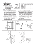
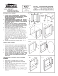
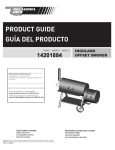
INSTALLATION INSTRUCTIONS
MODEL: 62BK244CBK(X), 62BK244CCN(X),
62BK244CCY(X), 62BK244CMP,
62BK244TBK(X), 62BK244TCY(X),
62BK244TGK(X), 62BK244TMP
RECESSED MOUNTED, STEEL
BATH CABINETS
MODEL
NO.
62BK244CBK(X)
62BK244CCN(X)
62BK244CCY(X)
62BK244CMP
62BK244TBK(X)
62BK244TCY(X)
62BK244TGK(X)
62BK244TMP
For help, call us toll
free!
1-800-325-8351
Register your product online at www.nutone.com/register
INSTALLATION of CABINET
1.
2.
3.
4.
5.
6.
Carefully remove all packing material. Place hardware
packages, shelves and door aside until needed. Hardware
and shelves are located in the fillers identified by “Hardware
Enclosed” tape.
Determine desired location of cabinet on wall. Mark wall to
show wall opening size (see dimension chart). Generally, the
recommended height to the center of the cabinet is 64” from
the floor. (Fig. 1)
CAUTION: Wall studs, plumbing or electrical lines that
interfere must be removed or relocated. Cut wall opening,
being careful not to damage the surrounding wall surface.
Insert framing to support all plaster board edges.
Prepare the mounting screws by placing the screws into the
plastic bases. (Fig. 2)
Note: For ease of installation, an additional person is
recommended. Insert cabinet into wall opening. (Fig.3)
Ensure the cabinet is plumb and level. If necessary use a
carpenter’s level and shim corners of cabinet. Secure to wall
studs through the four (4) mounting holes inside cabinet,
using the screws that have been placed into the plastic
bases. (Fig. 4) Do not over tighten the mounting screws as
the body side wall may bend and prevent proper shelf
installation. Only tighten screws until they are flush with the
body.
Snap the screw covers over the screw bases. (Fig.5)
WALL OPENING
W
H
D
141/4 24 4
141/4 24 4
141/4 24 4
141/4 24 4
141/4 24 4
141/4 24 4
141/4 24 4
141/4 24 4
OVERALL SIZE
W H
D
161/2 261/2 51/4
161/2 261/2 51/4
161/2 261/2 51/4
161/2 261/2 51/4
161/2 261/2 51/4
161/2 261/2 51/4
161/2 261/2 51/4
161/2 261/2 51/4
Fig. 2
Fig. 1
H
Approx.
64" to
Floor
Insert screw
through clear
plastic base
D
W
Fig. 3
Fig. 4
Wall
Opening
Mounting
Screws
Mounting
screw into
mounting
hole
Cabinet
Body
Fig. 6
Fig. 5
Snap on Cover
Hinge Mounted
to Door
Cover
Screw
INSTALLATION of DOORS
1.
2.
3.
Remove hinges and screws from hardware bag. Mount
hinge unit on door as shown in Fig. 6 securing with screws
provided.
Install the door by inserting door side of the hinge into the
bracket on the body shown in Fig. 7.
Check door for proper alignment. If the door needs to be
adjusted please refer to the adjustment procedures in Fig. 8.
Base
Fig. 7
Hinge Mounted
to Cabinet
3.
4.
5.
Select where you want the shelves to be placed.
Insert two (2) shelf brackets at each end of the shelf location.
(Fig. 9).
Set shelves in place on the shelf brackets, pressing down
on the shelf to lock in place. (Fig. 9).
Remove hole plugs from hardware bag and place in
remaining holes. (Fig. 10).
Remove bumpers from hardware bag and position to body.
(Refer to Service Parts Drawing - Key No. 9 for bumper
locations).
Fig. 8
Door Adjustment
This screw for
up and down
adjustments
This screw
for depth
adjustments
INSTALLATION of SHELVES, HOLE PLUGS AND BUMPERS
1.
2.
Hook bottom of
hinge into place
on the bracket
Press down
on hinge until it
clips in place
Fig. 9
This screw
for left and right
adjustments
Fig. 10
2
4
5
2
5
6
3
1
9
7
8
SERVICE PARTS
KEY
NO
1
2
3
4
5
6
7
8
9
DESCRIPTION
Door Assembly
Hinge Assm w/screws
Screw, hinge (4 req)
Hole Plug
Screw cover & base
Mounting screw
#8 X 11/2”
Shelf supports
Shelf, glass
Bumpers
62BK244CBK(X)
A97016604
A97016214
A99160423
A99111301
A99111248
62BK244CCN(X)
A97016606
A97016214
A99160423
A99111301
A99111248
*
A99111300
A99050275
7189
*
A99111300
A99050275
7189
* Standard hardware - may be purchased locally.
Order replacement parts by “PART NUMBER” - NOT by KEY NO.”
MIRROR CARE
• Use only clean warm water and a clean, soft,
lint-free cloth.
• DO NOT USE cleaners that contain solutions of
ammonia, vinegar, or chlorine.
• DO NOT USE powdered cleansers or steel wool.
• Never spray cleaning agent directly on mirror,
especially on exposed edges and mirror backing.
Apply cleaner to soft cloth and wipe mirror. Dry
mirror thoroughly.
• Keep mirror dry. A well ventilated bath room is
important.
PART NUMBER
62BK244CCY(X) 62BK244CMP 62BK244TBK(X) 62BK244TCY(X) 62BK244TGK(X) 62BK244TMP
A97016605
A97016607
A97016600
A97016601
A97016603
A97016602
A97016214
A97016214
A97016214
A97016214
A97016214
A97016214
A99160423
A99160423
A99160423
A99160423
A99160423
A99160423
A99111301
A99111301
A99111301
A99111301
A99111301
A99111301
A99111248
A99111248
A99111248
A99111248
A99111248
A99111248
*
A99111300
A99050275
7189
*
A99111300
A99050275
7189
*
A99111300
A99050275
7189
*
A99111300
A99050275
7189
*
A99111300
A99050275
7189
*
A99111300
A9905275
7189
One Year Limited Warranty
WARRANTY OWNER: Broan-NuTone warrants to the original consumer purchaser of its products that such products will be free from defects in
materials or workmanship for a period of one (1) year from the date of original purchase. THERE ARE NO OTHER WARRANTIES, EXPRESS
OR IMPLIED, INCLUDING, BUT NOT LIMITED TO, IMPLIED WARRANTIES OF MERCHANTABILITY OR FITNESS FOR A PARTICULAR
PURPOSE.
During this one year period, Broan-NuTone will, at its option, repair or replace, without charge, any product or part which is found to be defective
under normal use and service. THIS WARRANTY DOES NOT EXTEND TO FLUORESCENT LAMP STARTERS OR TUBES, FILTERS, DUCT,
ROOF CAPS, WALL CAPS AND OTHER ACCESSORIES FOR DUCTING. This warranty does not cover (a) normal maintenance and service or
(b) any products or parts which have been subject to misuse, negligence, accident, improper maintenance or repair (other than by Broan-NuTone),
faulty installation or installation contrary to recommended installation instructions.
The duration of any implied warranty is limited to the one year period as specified for the express warranty. Some states do not allow limitation on
how long an implied warranty lasts, so the above limitation may not apply to you.
BROAN-NUTONE’S OBLIGATION TO REPAIR OR REPLACE, AT BROAN-NUTONE’S OPTION, SHALL BE THE PURCHASER’S SOLE AND
EXCLUSIVE REMEDY UNDER THIS WARRANTY. BROAN-NUTONE SHALL NOT BE LIABLE FOR INCIDENTAL, CONSEQUENTIAL OR SPECIAL
DAMAGES ARISING OUT OF OR IN CONNECTION WITH PRODUCT USE OR PERFORMANCE. Some states do not allow the exclusion or
limitation of incidental or consequential damages, so the above limitation or exclusion may not apply to you. This warranty gives you specific legal
rights, and you may also have other rights, which vary from state to state. This warranty supersedes all prior warranties.
WARRANTY SERVICE: To qualify for warranty service, you must (a) notify Broan-NuTone at the address or telephone number below, (b)
give the model number and part identification and (c) describe the nature of any defect in the product or part. At the time of requesting
warranty service, you must present evidence of the original purchase date.
Date of Installation
Builder or Installer
Model No. and Product Description
IF YOU NEED ASSISTANCE OR SERVICE - CONTACT:
Broan-NuTone LLC, 501 S. Wilhite Street, Cleburne, TX 76031 www.nutone.com (1-800-325-8351)
INSTRUCCIONES DE INSTALACION
MODELO: 62BK244CBK(X), 62BK244CCN(X),
62BK244CCY(X), 62BK244CMP,
62BK244TBK(X), 62BK244TCY(X),
62BK244TGK(X), 62BK244TMP
AHUECADO GABINETS MONTADO,
DE ACERO DEL BANO
Para la ayuda,
llamenos peaje libres!
1-800-325-8351
Coloque su producto en linea en
www.nutone.com/register
INSTALACION del GABINETE
1.
2.
3.
4.
5.
6.
Quite cuidadosamente todo el material de embalaje. Coloque
los paquetes, los estantes y la puerta del hardware a un lado
hasta que esta necesitado. El hardware y los estantes estan
situados en los llenadores identificados por la cinta incluida
“hardware”.
Determine la localizacion deseada del gabinete en la pared.
Marque la pared para demostrar tamano de la abertura de la
pared (vease la carta de la dimension). Generalmente, la
altura recomendada al centro del bacine es el 163cm del piso.
(Fig. 1)
PRECAUCION: Emparede los pernos prisioneros, plomeria
o las electricas que interfieren deben ser quitadas o ser
vueltas a poner. Corte la abertura de la pared, teniendo
cuidado de no danar la superficie de la pared circundante.
Inserte enmarcar para apoyar todos los bordes del tablero de
yeso.
Prepare los tornillos de montaje colocando los tornillos en
las bases plasticas.
Nota: Para la facilidad de la instalacion, recomiendan una
persona adicional. Inserte el gabinete en la abertura de la
pared. (Fig. 3) Asegura el gabinete es vertical y llana. En
caso de necesidad utilice las esquinas del nivel y de la
calza de un carpintero del gabinete. Asegure a los pernos
prisioneros de la pared a traves de los cuatro (4) agujeros
de montaje dentro del gabinete, usando los tornillos que
se han colocado en las bases plasticas. (Fig 4) Excedente
no aprieta los tornillos de montaje mientras que la pared el
lateral de carrociria puede doblar y prevenir la instalacion
apropiada del estante. Apriete solamente los tornillos
hasta que son rasantes con el cuerpo.
Encaje a presion el onver de las cubiertas del tornillo las
bases de tornillo. (Fig 5)
INSTALACION de PUERTAS
1.
2.
3.
Quite las bisagras y los tornillos de bolso del hardware. Monte la
unidad de la bisagra en puerta segun lo demostrado en Fig. 6
que asegura con los tornillos proporcionados.
Instale la puerta este insertando el lado de la puerta de la bisagra
en el soporte en el cuerpo demostrado en fig. 7.
Compruebe la puerta para saber si hay la alineacion apropiada.
Si la puerta necesita ser ajustado por favor refiera a los
procedimientos de ajuste en fig. 8.
INSTALACION de ESTANTES, de ENCHUFES del AGUJERO Y
de TOPES
1.
2.
3.
4.
5.
NUMERO DE
MODELO
62BK244CBK(X)
62BK244CCN(X)
62BK244CCY(X)
62BK244CMP
62BK244TBK(X)
62BK244TCY(X)
62BK244TGK(X)
62BK244TMP
ABERTURA DE LA PARED
ANCH ALT PROF
362
610
102
362
610
102
362
610
102
362
610
102
362
610
102
362
610
102
362
610
102
362
610
102
TOMANO TOTAL
ANCH ALT PROF
419
673
133
419
673
133
419
673
133
419
673
133
419
673
133
419
673
133
419
673
133
419
673
133
Fig. 2
Fig. 1
Inserte el tornillo
a traves de base
plastica clara
ALT
Aproximadamente
el 163cm al piso
PROF
ANCH
Fig. 3
Fig. 4
Abertura De
la Pared
Tornillos De
Montaje
Cuerpo Del
Gabinete
Fig. 5
Tornillos de
montaje en
el agujero
de montaje
Fig. 6
Broche de Presion Cubierta
en la Cubierta
Bisagra montado
a la puerta
Tornillo
Base
Fig. 8
Fig. 7
Bisagra montade
a la puerta
Enganche el fondo de
la bisagra en lugar
en el soporte
Ajuste De la Puerta
Este tornillo para ariba
y abajo de los ajustes
Este tornillo para
el ajuste de la
profundidad
Presione abajo en la
bisagra hasta que acorta
en lugar
Seleccione donde usted quisiera que los estantes fueran
colocados.
Soportes del estante en cada final de la localizacion del estante.
Fig. 9
(Fig. 9)
Estatnes determinados en lugar en los soportes del estante y
empujan hacia abajo a la cerradura en lugar. (Fig. 9)
Quitan los enchufes del agujero de bolso del hardware y los
colocan en agujeros restantes. (Fig. 10).
Quite los topes de bolso del hardware y coloquelos al cuerpo.
(Refiera a las piezas de servicio que dibujan - numero dominante
9 para las localizaciones de parachoques.)
Este tornillo para los
ajustes izquierdos y derechos
Fig. 10
2
4
5
2
5
6
3
1
9
7
8
PIEZAS DE SERVICIO
NUMERO
DOMINANTE
1
2
3
4
5
6
7
8
9
DESCRIPCION
Asamblea De
la Puerta
Montaje de
bisagra con
los tornillos
Tornillo
bisagra
Enchufe
DelAgujero
Cubierta y
base del tornillo
Tornillo de
montaje
#8 x 11/2”
Estante Ayuda
Estante, cristal
Topes
NUMERO DE PIEZA
62BK244CBK(X) 62BK244CCN(X) 62BK244CCY(X) 62BK244CMP 62BK244TBK(X) 62BK244TCY(X) 62BK244TGK(X) 62BK244TMP
A97016604
A97016606
A97016605
A97016607
A97016600
A97016601
A97016603
A97016602
A97016214
A97016214
A97016214
A97016214
A97016214
A97016214
A97016214
A97016214
A99160423
A99160423
A99160423
A99160423
A99160423
A99160423
A99160423
A99160423
A99111301
A99111301
A99111301
A99111301
A99111301
A99111301
A99111301
A99111301
A99111248
A99111248
A99111248
A99111248
A99111248
A99111248
A99111248
A99111248
*
A99111300
A99050275
7189
*
A99111300
A99050275
7189
*
A99111300
A99050275
7189
*
A99111300
A99050275
7189
*
A99111300
A99050275
7189
*
A99111300
A99050275
7189
*
A99111300
A99050275
7189
*
A99111300
A99050275
7189
*Ferreteria estandar - puede ser cmprado localmnte.
Pida los piezas de recambio por “NUMERO de PIEZA” - NO por el “NUMERO DOMINANTE”
Garantia Limitada de un Año
GARANTÍA DEL PROPIETARIO: Broan-NuTone garantiza al comprador consumidor original de sus productos, por el período de un (1) año desde la fecha original de compra, que tales
productos están libres de defectos en material y mano de obra. NO HAY OTRAS GRANTÍAS, EXPRESADOS O SOBREENTENDIDAS, INCLUYENDO, PERO NO LIMITADAS A, GRANTÍAS
NO EXPRESADAS DE MERCHNTIBILIDAD O ADAPTABLES A UN PROPÓSITO EN PARTICULAR.
Durante este período de un año, Broan-NuTone reparará o reemplazará a su opción y sin costo, cualquier producto o parte que se encuentre defectuoso bajo condiciones normales de uso y
servicio. ESTA GARANTÍA NO CUBRE A LOS ARRANCADORES PARA LÁMPARAS FLUORESCENTES O A LOS TUBOS FLUORESCENTES, FILTROS, DUCTOS, TAPAS DE TECHO, TAPAS
DE PARED Y OTROS ACCESORIOS PARA CANALIZACIÓN. Esta granatía no cubre (a) Mantenimiento y servicios normales (b) Productos o partes sujetos al mal uso, negligencia, accidente,
mantenimiento inadecuado o reparaciones (port otros ajenos a Broan-NuTone), instalación defectusoa o a una instalación contraria a las instrucciones de instalación recomendadas.
La duración de cualquier garantia no expresada está limitada a un periodo de un año según se especifica en la garantia expresada. Algunos estados no permiten limitación en cuanto a la
duración de una grantia no expresada, por lo que la limitación arriba indicada puede que no se apliqué a Ud.
LA OBLIGACIÓN DE BROAN-NUTONE DE REPARAR O REEMPLAZAR A SU OPCIÓN, SERÁ EL ÚNICO Y EXCLUSIVO RECURSO QUE TENDRÁ EL COMPRADOR BAJO
ESTA GARANTÍA. BROAN-NUTONE NO SERÁ RESPONSABLE POR DAÑOS INCIDENTALES, CONSECUENTES O ESPECIALES QUE RESULTEN A CONSECUENCIA O SEAN
INDEPENDIENTE DEL USO O DESEMPEÑO DEL PRODUCTO. Algunos estados no permiten la exclusión o limitación de daños incidentals o consecuentes, de modo que la limitación o
exclusión arriba indicada pueda que no se aplique a Ud. Esta garantia le proporciona derechos legales especificos, y Ud.puede tener otros derechos, los cuales varían de estado a estado.
Esta garantias reemplaza a todas las garantías anteriores..
SERVICO DE GARANTÍA: Para tener derecho al servicio de garantía, Ud. debe (a) Notificar a Broan-NuTone a la dirección o el número de teléfono abajo, (b) indicar el número
de modelo y la identifación de la party y (c) describir la naturaleza de cualquier defecto en la producto o parte. Al momento de solicitor el servicio por la garantía, Ud. debe
presentar la evidencia de la fecha original de compra.
CUIDADO DEL ESPEJO
•
•
•
•
Fecha de la instalación
Constructor o instalador
Número de modelo y descripción del producto
SI NECESITA ASISTENCIA O SERIVIVIO - CONTACTO:
Broan-NuTone LLC, 501 S. Wilhite Street, Cleburne, TX 76031 www.nutone.com (1-800-325-8351)
•
Utilice solamente el agua caliente limpia y un
trapo sin peluse limpio, suave.
No utilitce los limpiadores que contienen
soluciones del amoniaco del vinagre, o de
la clorina.
No utilice las despedregadoras o las lanas de
acero pulverizadas.
Nunca rocie el agente de limpieza directamente
en el espejo, especialmente en los bordes
y el forro expuestos del espejo. Aplique el
limpiador al pano suave y limpie el espejo.
Seque el espejo a fondo.
Mantenga el espejo seco. Un cuarto de bano
bien ventilado es importante.
A99044194 A