1
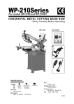
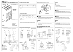
Item# 145765
Automatic Metal-Cutting Band Saw
User’s Manual
Assembly and Operation Instructions
MADE IN CHINA
Quick-Start Guide
ATTENTION: READ AND FOLLOW UNPACKING & ASSEMBLY GUIDE BEFORE
OPERATION.
1. Front Locking Bolt
2. Band Saw.
3. Locking device between saw arch and table.
4. Rear Locking Bolt
5. Front Wheels
6. Rear Wheels
7. Length-restricting device for workpiece
UNPACKING
Step 1. Snip the carton wrapping belt near the wooden pallet, pull the nails from the
carton and pallet, then the carton can be taken away.
Step 2. The band saw can be removed from the pallet by removing the bolts and
connecting parts (1 & 4 of Fig. A). Remove the bolt and connecting parts of the locking
device (3 of Fig. A), then the saw arch can be raised.
ASSEMBLY
Step 1. Assemble the front & rear wheels (5 & 6 of Fig. B).
Step 2. By removing the locking device (3 of Fig. A), the saw arch could be raised. The
saw arch will stay in position if the hydraulic valve (A & B of Fig. B) is “Off”. The saw
arch cannot be pressed down by using external force. You must put the hydraulic valve
(A of Fig. B) in “On” position and then switch the flow control (B of Fig. B) to lower the
saw arch. The speed of the saw arch going down depends on the range you choose for
the flow control valve (B of Fig. B).
Note: The hydraulic valve (A of Fig. B) is “Off” when its handle is in horizontal direction,
and “On” when its handle is vertical.
Page 1 of 15
For technical questions and replacement parts, please call 1-800-556-7885.
Thank you very much for choosing a Northern Industrial Product! For future reference, please
complete the owner’s record below:
Model: _______________
Purchase Date: _______________
Save the receipt, warranty and these instructions. It is important that you read the entire instruction
sheet to become familiar with this product before you begin using it.
This machine is designed for certain applications only. It is strongly recommended that this machine
is not modified and/or used for any application other than that for which it was designed. If you have
any questions relative to a particular application, DO NOT use the machine until you have first
contacted your dealer to determine if it can or should be performed on the product.
Before using the Automatic Metal-Cutting band Saw, please read the following instructions carefully.
WARNING: FAILURE TO FOLLOW THESE RULES MAY RESULT
IN SERIOUS PERSONAL INJURY
AS WITH ALL MACHINERY, THERE ARE CERTAIN HAZARDS INVOLVED WITH OPERATION AND USE OF
THE MACHINE. USING THE MACHINE WITH RESPECT AND CAUTION WILL CONSIDERABLY REDUCE THE
POSSIBILITY OF PERSONAL INJURY. HOWEVER, IF NORMAL SAFETY PRECAUTIONS ARE OVERLOOKED
OR IGNORED, PERSONAL INJURY TO THE OPERATOR MAY RESULT.
THIS MACHINE WAS DESIGNED FOR CERTAIN APPLICATION ONLY. WE STRONGLY RECOMMEND THAT
THIS MACHINE NOT BE MODIFIED AND OR USED FOR ANY APPLICATION OTHER THAN FOR WHICH IT
WAS DESIGNED. IF YOU HAVE ANY QUESTIONS RELATIVE TO ITS APPLICATION, DO NOT USE THE
MACHINE UNTIL YOU HAVE HAD DETAIL INSTRUCTION FROM YOUR DEALER.
SAFETY RULES FOR ALL TOOLS
1. For your own safety, read instruction manual before operating the tool. Learn the tools application
and limitations as well as the specific hazards of operating it.
2. Always keep guards in place and in working order.
3. Ground all tools. If tool is equipped with three-prong plug, it should be plugged into a three-hole
electrical receptacle. If an adapter is used to accommodate a two-prong receptacle, the adapter plug
must be attached to a known ground. Never remove the third prong.
4. Always remove adjusting keys and wrenches before operating machine. Form a habit of checking
to see that keys and adjusting wrenches are removed from tool before turning it “on”.
5. Keep work area clean. Cluttered areas and benches invite accidents.
6. Don’t use in dangerous environment. Don’t use power tools in damp or wet locations, or expose
them to rain. Keep work area well lit.
7. Keep children and visitors away. All children and visitors should be kept a safe distance from work
area.
8. Make workshop child-proof with padlocks, master switches, or by removing starter keys.
9. Use the right tool. Don’t force tool or attachment to do a job for which it was not designed.
10. Wear proper apparel. No loose clothing, gloves, neckties, rings, bracelets, or other jewelry that
can get caught in moving parts. Non-slip foot wear is recommended. Wear protective hair covering
to contain long hair.
Page 2 of 15
11. Always wear eye protection, Refer to A.N.S.I Z87.1 Standard for appropriate recommendations.
Also use a face or dust mask if cutting operation is dusty.
12. Always secure work with clamps or a vise. It’s safer than using your hand and frees both hands
to operate tool.
13. Don’t overreach - keep proper footing and balance at all times.
14. Maintain tools in top condition. Keep tools sharp and clean for best and safest performance.
Follow instructions for lubricating and changing accessories.
15. Disconnect tools before servicing and when changing accessories such as blades, bits, cutters,
etc.
16. Use recommended accessories. Consult the owner’s manual for recommended accessories.
The use of improper accessories may cause hazards.
17. Avoid accidental starting. Make sure Switch is in “OFF” position before plugging in power cord.
18. Never stand on the tool. Serious injury could occur if the tool is tipped or if the cutting tool is
accidentally contacted.
19. Check damaged parts before further use of the tool. A guard or other part that is damaged
should be carefully checked to ensure that it will operate properly and perform its intended function.
Check for alignment of moving parts, binding of moving parts, breakage of parts, mounting, and any
other conditions that may affect its operation. A guard or other part that is damaged should be
properly repaired or replaced.
20. Note direction of feed. Feed work into a blade or cutter against the direction of rotation of the
blade or cutter only.
21. Never leave the tool running unattended. Turn the power off and do not leave the tool until it
comes to a complete stop.
22. Do not operate tool while under the influence of drugs, alcohol or any medication.
23. Make sure tool is disconnected from power supply while motor is being mounted, connected or
reconnected.
ADDITIONAL SAFETY RULES FOR HORIZONTAL BAND SAWS
1. Adjust and position the blade guide arm before starting cut.
2. Keep blade guide arm tight. A loose blade guide arm will affect sawing accuracy.
3. Make sure that blade tension and blade tracking are properly adjusted.
4. Re-check blade tension after initial cut with a new blade.
5. To prolong blade life, always release blade tension at the end of each workday.
6. Make sure blade speed is set correctly for material being cut.
7. Check for proper blade size and type based on the material being cut.
8. Stop the machine before putting material in the vise and clamping it well.
9. Always have stock firmly clamped in vise before starting to cut.
10. Always keep hands and fingers away from the blade.
11. Check coolant daily: Low coolant level can cause foaming and high blade temperatures. Dirty or
weak coolant can clog pump, cause crooked cut, low cutting rate and permanent blade failure. Dirty
coolant can cause the growth of bacteria with ensuing skin irritation.
Page 3 of 15
12. When cutting magnesium never use soluble oils or emulsions (oil-water mix) as water will greatly
intensify any accidental magnesium chip fire. See your industrial coolant supplier for specific coolant
recommendations when cutting magnesium.
13. To prevent corrosion of machine surface when a soluble oil is used as coolant, pay particular
attention to wiping dry the surfaces where fluid accumulates and does not evaporate quickly, such
as between the machine bed and vise.
14. Stop the machine before removing chips.
15. Make all adjustments with the power off.
16. Disconnect machine from power source when making repairs.
17. Shut off power and clean the Band Saw and work area before leaving the machine.
WIRING DIAGRAM
TOGGLE SWITCH SINGLE PHASE
ASSEMBLY
A 1 HP, 1725 motor, split phase or capacitor-start, is recommended for best economical
performance.
The characteristics of this machine:
1. If you want to shift the speed, you may shift the speed directly by operating the handle beside the
gearbox. And you may choose the appropriate speed in accordance with the material of the
workpiece.
2. After the cut processing is completed, the power will turn off automatically.
Page 4 of 15
3. Quick-set vise clamp.
4. Low noise level during operating.
Note:
If you want to shift the speed of the gear box, you have to wait till the machine stops running. Then
you may operate the shifting. Please make sure that you do not shift the speed while cutting.
Please check the engine oil of the gearbox
regularly.
Change the #80-#90 engine oil every 500
working hours.
Steps for operating the gearbox:
1. Before you shift the speed, you have to cut
off the source of the electricity, then you may check if the motor stops running completely. After that,
remove the saw blade from the piece of work.
2. To insert the location pin smoothly, move the saw blade back and forth, bringing the shifting
handle to a suitable location where you can insert the location pin into the locate hole.
OPERATION
WORK SET UP
1. Raise the saw arch to a 45ºposition with the table and built-in steady rest locks.
2. Open the vise to clamp the workpiece to be cut securely by rotating the handle.
3. Use a sliding bracket to keep balance if the workpiece is too long.
4. Select the adequate speed for the material you are cutting.
5. Switch on the power and lift the saw arch to the top and lower with the hydraulic flow control.
6. Adjust the coolant & lubricant switch to the appropriate level.
7. Turn off the power supply after you finish work.
NOTE: Never turn off the motor when blade is cutting.
WORK STOP ADJUSTMENT
1. Loosen the thumb screw holding the work stop casting to the shaft.
2. Adjust the work stop casting to the desired position.
3. Rotate the work stop to as close to the bottom of the cut as possible.
4. Tighten thumb screw.
5. DO NOT ALLOW the blade to rest on the work while the motor is shut off.
CONVERTING FOR VERTICAL USE
Notching slitting, contour work may be done with the saw in the vertical position in the following
manors:
1. Rotate the head to the vertical position.
2. Assemble a 10”x10” table (an option that may be purchased from your dealer) to the guide bar
using the screws provided and the guide bar knob.
Page 5 of 15
BLADE SPEEDS
When using your band saw always change the blade speed to best suit the material being cut. The
Material Cutting Chart gives suggested settings for several materials.
MATERIAL CUTTING CHART
Speed F.P.M
Material
60Hz
50Hz
Tools, Stainless
Alloy Steel
100
83
Bearing Bronze
Medium or High
Carbon Steels
180
150
Hard Brass or Bronze
Aluminum
235
195
Plastic
BLADE DIRECTION OF TRAVEL
Be sure the blade is assembled to the pulleys, such that the vertical edge engages the workpiece
first.
BLADE MOVEMENT
STARTING SAW
CAUTION: NEVER OPERATE SAW WITHOUT BLADE GUARDS IN PLACE.
Be sure the blade is not in contact with the work when the motor is started. Start the motor, allow the
saw to come to full speed, and then begin the cut by letting the head down slowly onto the work. DO
NOT DROP OR FORCE. Let the weight of the saw head provide the cutting force. The saw
automatically shuts off at the end of the cut.
BLADE SELECTION
A 8-tooth per inch, general-use blade is furnished with this Metal-Cutting Sand Saw. Additional
blades in 4, 6, 8, and 10 tooth sizes are available. The choice of blade pitch is governed by the
thickness of the work to be cut: the thinner the workpiece, the more teeth advised. A minimum of
three (3) teeth should engage the workpiece at all times for proper cutting. If the teeth of the blade
are too far apart that they straddle the work, severe damage can be done to the workpiece and to
the blade.
Selection of band saw blades:
Page 6 of 15
1. Bi-metal band saw blade is suitable for metal workpiece such as carbon steel, alloy steel, and
stainless steel.
2. Hardback carbon band saw blade is suitable for low-rigidity small metal workpieces and hard
plastic.
3. Flexback carbon band saw blades are suitable for wood, fiber glass and plastic.
4. Carbide grit edge band saw blades are suitable for plumbago, carbon product and alveolate
material, etc.
CHANGING THE BLADE
Raise the saw arch to vertical position and open the blade guards. Loosen tension screw knob to
sufficiently allow the saw blade to slip off the wheels. Install the new blade with teeth slanting toward
the motor as follows:
1. Place the blade in between each of the guide bearings.
2. Slip the blade around the motor pulley (bottom) with the left hand and hold in position.
3. Hold the blade taut against the motor pulley by pulling the blade upward with the right hand which
is placed at the top of the blade.
4. Remove left hand from bottom pulley and place it at the top side of the blade to continue the
application on the upward pull on the blade.
5. Remove right hand from blade and adjust the position of the top pulley to permit left hand to slip
the blade around the pulley using the thumb, index and little finger as guides.
6. Adjust the blade tension knob clockwise until no blade slippage occurs, Do not tighten
excessively.
7. Replace the blade guards.
8. Place 2-3 drops of oil on the blade.
USAGE OF THE QUICK VISE
The workpiece is placed between the vise jaws with the amount to be cut off extending out past the
blade. Your machine is equipped with a “quick-action” vise jaw which allows you to instantly position
the moveable vise jaw (B). Simply turn hand-wheel (A) counterclockwise 1/2 turn and move the vise
jaw (B) to the desired position. Then tighten the vise jaw (B) against the workpiece by turning handwheel clockwise.
Page 7 of 15
QUICK VISE ADJUSTMENT FOR ANGLE CUT
1. Loosen the A, B, C and D screws.
2. Adjust rear vise to the threaded hole position.
(E)
3. Set the scale to the desired angle.
4. Adjust the front vise (F) to parallel the rear vise
(E).
5. Tighten the A, B, C and D screws.
BLADE GUIDE BEARING ADJUSTMENT
ATTENTION: This is the most important adjustment on your saw. It is impossible to get satisfactory
work from your saw if the blade guides are not properly adjusted. The blade guide bearings on your
Metal-Cutting Band Saw are adjusted and power-tested with several test cuts before leaving the
factory to insure proper setting. The need for adjustment should rarely occur when the saw is used
properly. If the guides do get out of adjustment, it is extremely important to readjust immediately. If
improper adjustment is maintained, the blade will not cut straight, and if the situation is not corrected
it will cause serious blade damage.
Because guide adjustment is a critical factor in the performance of you saw, it is always best to try a
new blade to see if this corrects poor cutting before beginning to adjust. If a blade becomes dull on
one side sooner than the other, for example, it will begin cutting crooked. A blade change will correct
this problem while the guide adjustment will not. If a new blade does not correct the problem, check
the blade guides for proper spacing.
NOTE: There should be from 000 (just touching) to 001 clearance between the blade and guide
bearings. To obtain this clearance adjust as follows:
1. The inner guide bearing is fixed and cannot be adjusted.
2. The outer guide bearing is mounted to an eccentric bushing and can be adjusted.
3. Loosen the nut while holding the bolt with an Allen wrench.
4. Position the eccentric bushing by turning the bolt to the desired position of clearance.
5. Tighten the nut.
BLADE TRACK ADJUSTMENT
1. Open the blade guard.
2. Remove the blade guide assemblies (top and bottom).
3. Loosen the hex head screw in the tilting mechanism to a point where it is loose but still snug.
4. With the machine running, adjust both the set screw and blade tension knob simultaneously to
keep constant tension on the blade. The set screw and blade tension knob are always turned in
opposite directions, i.e., when one is turned clockwise, the other is turned counterclockwise. The
blade is tracking properly when the backside just touches the shoulder of pulley or a slight gap
appears near the center line of the pulley. Care should be taken not to over tighten the saw blade
since this will give a false adjustment and limit life of the blade.
5. Tighten the hex head screw in tilting mechanism. IMPORTANT: Sometimes in trying to make this
critical adjustment, it is possible to cause the basic setting to be misaligned. Should this occur,
proceed as follows:
a. Loosen the set screw and back it out as far as it can go and still remain in the threaded hole.
Page 8 of 15
b. Turn the hex head screw clockwise until it stops (do not tighten).
c. Turn the set screw clockwise until it bottoms, then continue for half a turn and check the
tracking by turning on the machine,
d. lf further adjustment is required, go back to step 4.
6. Turn off power to the machine.
7. Replace blade guide assemblies (it may be necessary to loosen the blade tension slightly).
8. Adjust the vertical position of blade guide bearing assemblies so that the backside of the blade
just touches the ball bearing.
9. Make a final run to check tracking. If necessary to adjust, go back to step 4.
10. Replace the blade guards.
MAINTENANCE
CAUTION: MAKE CERTAIN THAT THE UNIT IS DISCONNECTED FROM THE POWER SOURCE
BEFORE ATTEMPTING TO SERVICE OR REMOVE ANY COMPONENT.
LUBRICATION
Lubricate the following components using SAE-30 oil as noted:
1. BalI-bearing: None.
2. Driven pulley bearing: 6-8 drops a week.
3. Vise lead screw as needed.
4. The drive gears run in an oil bath and will not require a lubricant change more often than once a
year, unless the lubricant is accidentally contaminated or a leak occurs because of improper
replacement of the gear box cover. During the first few days of operation, the worm gear drive will
run hot. Unless the temperature exceeds 200 degrees, there is no cause for alarm.
Following lubricants may be used for the gearbox:
Atlantic Refinery Co. Mogul Cyl. Oil
Cities Service Optimus No. 6
Gulf Refinery Co Medium Gear Oil
Pure Oil Co. Park Clipper
TROUBLE SHOOTING
Page 9 of 15
SYMPTOM
Excessive Blade
Breakage
Permanent Blade
Dulling
POSSIBLE CAUSE (S)
1. Incorrect blade tension
2. Incorrect speed or feed
3. Material loose in vise
4. Blade rubs on wheel flange
5. Teeth too coarse for material
6. Teeth in contact with work before saw is started
7. Misaligned guides
8. Blade too thick for wheel diameter
9. Cracking at weld
1. Teeth too coarse
2. Too much speed
3. Inadequate feed pressure
4. Hard spots or scale in/on material
5. Work hardening of material (especially stainless
steel)
6. Blade installed backwards
7. Insufficient blade tension
1. Work not square
2. Feed pressure too great
Bad Cuts (Crooked)
Bad cuts (Rough)
Blade is twisting
Unusual Wear on
Side/Back of Blade
Teeth Ripping from
blade
Motor Running too
H t
slow
3. Guide bearing not adjusted properly
4. Inadequate blade tension
5. Blade guides spaced out too much
6. Dull blade
7. Speed incorrect
8. Blade guide assembly loose
9. Blade guide bearing assembly loose
10. Blade tracks too far away from wheel flanges
1. Too much speed of feed
2. Blade is too coarse
1. Cut is binding blade
2. Too much blade tension
1. Blade guides worn
2. Blade guide bearings not adjusted properly
3. Blade guide bearing bracket is loose
1. Tooth too coarse for work
2. Too heavy feed : too slow feed
3. Vibrating work piece
4. Gullets loading
1. Blade tension too high
2. Drive belt tension too high
3. Blade is too coarse for work (Pipes especially)
4. Blade is too fine for work (Heavier, softer material)
5. Gear not aligned properly
6. Gears need lubrication
7. Idler wheel needs lubrication
Page 10 of 15
CORRECTIVE ACTION
1. Adjust to where blade just does not slip on wheel
2. Check Machinist Handbook
3. Clamp work securely
4. Adjust wheel alignment
5. Check Machinist Handbook for recommended blade
6. Place blade in contact work after motor is started
7. Adjust
8. Use thinner blade
9. Make longer annealing cycle
1. Use finer tooth blade
2. Try next lower speed
3. Decrease spring tension on side of saw
4. Reduce speed increase feed pressure (Scale)
increase feed pressure (Hard Spots)
5. Increase feed pressure by reducing spring tension
6. Remove blade twist inside out and reinstall blade.
7. Increase tension to proper level
1. Adjust vise to be square with blade. Always clamp
Work tightly in vise.
2. Reduce pressure by increasing spring tension on side
of saw.
3. Adjust guide bearings to 001 greater than max.
thickness, including weld of the saw.
4. Increase blade tension a little at a time
5. Move guides as close to work as possible
6. Replace blade
7 Check manual for recommended speeds
8. Tighten
9. Tighten
10. Retrack blade according to operating instructions
1. Reduce speed and feed
2. Replace with finer blade
1. Decrease feed pressure
2. Decrease blade tension
1. Replace
2. Adjust as per operators’ manual
3. Tighten
1. Use finer tooth blade
2. Increase feed pressure and/or speed
3. Clamp work securely
4. Use coarse tooth blade or brush to remove chips
1. Reduce tension on blade
2. Reduce tension on drive belt
3. Use finer blade
4. Use coarser blade
5. Adjust gears so that worm is in center of gear
6. Check oil bath
7. Oil bearing/shaft on idler wheel
ASSEMBLY DRAWING
Page 11 of 15
PARTS LIST
Ref #
Description
Ref #
Description
1
Valve Cock Support
10
C-Ring S8
2
S. Washer M8
11
Bolt M5x8
3
Set Screw Soc. Hd. M8x30mrn
12
B lade Cover (Front)
4
Nut 3/8NF
13
Water Nozzle
5
S.Washer 3/8"x2.2mm
14
Valve 1/4"
6
Blade AK justable (Front)
15
Bolt 3/16"x1/4"
7
Pin
16
Hose Button
8
Eccentric Shaft
17
Hose Plug 1/4"
9
Bearing 608ZZ
18
Hose
Page 12 of 15
Ref #
Description
Ref #
Description
19
Adjusting Knob 3/8"
58
Brush Holder
20
Plate Washer 3/8"X2x23
59
Bolt Screw 3/16”x1/2”
21
Adjustable Bracket (Front)
60
Brush
22
Bow-Saw
61
Bolt 1/4"x1/2"
23
Set Screw Soc. Hd. M8x16mm
62
Blade
24
Bolt M8x40mm
63
Gear Box & Motor
25
S. Washer 8.3x2
64
Piver Bracket
26
CAP M6x16
65
Place Washer M12X3x28
27
S.Washer M6x1.5mm
66
S. Washer M12x2.5
28
Slide
67
Bolt M12x40mm
29
Blade Tension Sliding Block
68
Bolt M12x40mm
30
Bolt 3/8"xl-1/2"
69
S. Washer M12 x2.5
31
S.Washer 10.5x2.3
70
Plate Washer M12x5
32
Plate Washer 3/8"x3
71
Foxed Vise
33
Adjustable Bracker (Rear)
72
Bolt M10x50
34
Blade Adjustable (Rear)
73
Set M8x8
35
S.Washer 5/16X23X3
74
Plate Washer 3/8x24x3
36
Deflector Plate
75
Free Vise
37
Bolt 1/4x1/2"
76
Table
38
Vertical Cutting Plate
77
Acme Screw
39
Plate Washer M8x2x18
78
Screw Servile
40
S. Washer M8 x2
79
C-Ring S 15
41
CAP M8x40mm
80
CAP Screw Soc. Hd. M6x1.0x25
42
Blade Wheel (Real)
81
Acme Screw Wheel
43
C-Ring S 25
82
Lever Knob
44
Bolt 1/4x1/2
83
Handle Screw
45
Plate 1/4x19x1.5
84
Bushing
46
Switch Hip
85
Set Screw Soc Hd M8x16
47
Plate Washer 3/8"x2x27
86
Bolt 3/8"x1-1/2"
48
Blade Adjustable Knob
87
Support Plate
Spring
88
Bolt M10x25rnm
49
Blade Wheel Shaft (Front)
89
S. Washer M10x2.2
50
Interval Ring
91
CAP 3/8x2 1/2
51
Bearing 6202ZZ
92
Support Rod
52
Blade Wheel (Front)
93
Bolt M8x15mm
53
Washer M8x18x2
94
Diaraph
54
Bolt M8x12mrn
95
/
55
Adjusting Knob 1/4"x1/2"
96
/
56
Blade Back Cover
98
Nut M10
57
Bolt 1/4"x1/2"
99
Length Fixing Plate
48-1
Page 13 of 15
Ref #
Description
Ref #
Description
100
Bolt M10x40mm
140
Bolt 1/2"x2-1/2"
101
Fixed Bolt
141
Wheel Shaft
102
Stock Stop Rod
142
Wheel
103
Bolt 3/16"x1/4"
143
Wheel Button
104
Filter Net Plate
144
Coolant Tank
105
Filter Net
145
Drain Plug
106
Switch Cover
146
Bolt 3/16"x3/8"
107
Toggle Switch
147
Pung Mount
108
Switch Cover Plate
148
Nut 3/16"
109
Switch Cover
149
Cooling Pump
110
Switch Brand
150
Front Support
111
Waterproof Cap
151
Bolt 3/16"x3/8"
112
Bolt 3/16"x3/8"
152
Bolt M6x10mm
113
Bolt 3/16"x3/8"
152-1
114
Bracket
153
Fuselage Plate
115
Pin 6x20
154
Water Frough Shelf
116
Stop Collar
155
Water Trough
117
Steet Balls
156
Bolt M6x30mm
118
Sheel Fragment
160
Nut M6
119
Bolt M5x8
161
Cylinder Support
120
Bolt 3/8x1-1/2
162
Plate Washer M10
121
Support
163
CAP M10x50mm
122
Nut 3/8x23x3
164
Cylinder
123
Plate Washer M8 x18x2
165
Bolt M12x60
124
S Washer M8
165-1
Washer M12
125
Bolt M8x25mm
166
Plate Washer M8x18x12
126
Rear Support
167
Bolt M6X20mm
127
Bolt MBx16mm
168
Cylinder Support
128
Cable Fixture
171
Spring
129
Wrie Flate
172
Spring Adjustable Rod
130
Plug
173
Plate Washer M10
131
Wrie Button
174
Bolt M10x25mm
132
Motor Wire
175
Spring Handle Bracket
133
Power Cable
176
Plate Washer3/8x2x23
134
Cabre Fixture
177
Nut 3/8
135
Bolt 3/16"x3/8"
178
Water Baffle
136
Washer M10x3x26
179
Cover
137
S Washer M10x22
180
Washer 1/4"x1.5x16
138
Bolt M10x25rnm
181
Screw 1/4"x1/2
139
Nut 1/2"
182
Cord Push
Page 14 of 15
NUT M6
WARNING!
Some dust created by power sanding, sawing, grinding,
drilling, and other construction activities contains
chemicals known to the State of California to cause
cancer, birth defects or other reproductive harm. Some
examples of these chemicals are:
● Lead from lead-based paints.
● Crystalline silica from bricks, cement and other masonry
products.
● Arsenic and chromium from chemically-treated lumber.
Your risk from these exposures varies, depending on how
often you do this type of works. To reduce your exposure
to these chemicals: Work in a well ventilated area, and
work with approved safety equipment, such as those dust
masks that are specially designed to filter out microscopic
particles.
Page 15 of 15