1
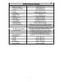
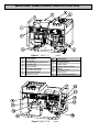
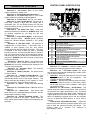
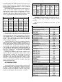
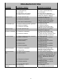
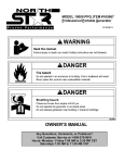
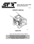
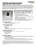
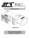
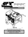
MODEL 5500 IPG, ITEM # 165926
Industrial Portable Generator
Pr o ve n
M165926A
Pe r f or ma n ce
OWNER’S MANUAL
5500 IPG
Shown with Optional Wheel Kit (Item # 165916)
Any Questions, Comments, or Problems?
Call Customer Service at 1-800-270-0810
Hours: Monday - Friday 7:30 AM to 5:30 PM
Saturday 7:30 to 11:30 AM CST
00219
THANK YOU
Thank you for purchasing a North Star Industrial Portable Series Generator. Your machine is
designed for long life, dependability, and the top performance you demand. Please take time
now to read through this manual so you can better understand the machine’s operation,
maintenance and safety precautions. Everyone who operates this generator must read and
understand this manual. The time you take now will prolong your generator’s life and prepare
you for its safe operation. Enjoy the exceptional performance of your North Star Industrial Series
Generator.
IMPORTANT
Make certain the operator:
- Reads and understands the manuals pertaining to this machine.
- Is instructed in safe and proper operation of this machine.
NOTICE
K-BAR Industries Incorporated reserves the right to make improvements in design and/or
changes in specifications at any time without incurring any obligation to install them on units
previously sold.
TABLE OF CONTENTS
Thank you
Specifications
Machine component identification
Generator features
Introduction
ANSI safety definitions
Rules for safe operation
Installation
Load application
Pre-start up preparation
Starting - Manual
Starting - Electric
Stopping
Engine care
Generator care
Troubleshooting
1
1
2
3
4-5
5
5
5-6
6
6-8
8
9
9
9
9
9
10
SPECIFICATIONS
Item Number
Ma ximum Output
Continuous Output
Voltage
Phase
Frequency
Power Factor
Engine
Engine Speed
Fuel Type
Fuel Capacity
Oil Capacity
Starting Method
120 V Receptacle
120/240 V Receptacle
Circuit Breaker
Grounding Post
Dimensions
Length
Width
Height
Dry Weight
Gross Weight
#165926
5500 Watts (W)
4500 Watts (W)
120 / 240 Volt (V)
Single phase (4-wire)
58.0-63.0 Hertz (H z)
1.0 p.f.
9 HP Honda GX270
3480-3780 RPM
Unleaded gasoline
6.5 gallons (24.6 L)
1.16 US quarts (1.1 L)
Electric Start / Recoil
(2) 20 Amp (A) duplex GFCI (NEMA 5-20R)
(1) 30 Amp (A) twistlock (NEMA L5-30R)
(1) 50 Amp (A) Straight Blade (NEMA 5-50R)
20 Amp (A) twistlock (NEMA L14-20R)
(2) 20 Amp (A) Thermal, push to reset
(1) 30 Amp (A) Thermal, push to reset
(1) 20 Amp (A) Magnetic, 2 Pole
Receives 10 Ga. wire or fork terminal
31.75” (80.6 cm)
23.63” (60.0 cm)
22.25” (56.5 cm)
195 lb. (88.6 kg)
240 lb. (109 kg)
2
MACHINE COMPONENT IDENTIFICATION
Figure 1 (Ref. 1-7)
Ref.
1
2
3
4
5
6
7
8
Description
00229
Ref.
Air Cleaner
Starting/Stopping Instructions
Oil Drain Plug
Control Panel
Gas Cap with Gauge
6.5 Gallon Gas Tank
Super Silent Muffler
Gas Drain Valve
Figure 2 (Ref. 8-16)
3
9
10
11
12
13
14
15
16
Description
Gas Line Valve
Generator Head
Battery & Box
Vibration Isolation Mount
Recoil
Fuel Valve Lever
Choke Lever
Electric Stop/Start Switch
00230
CONTROL PANEL IDENTIFICATION
GENERATOR FEATURES
Reference 1 - Air Cleaner. Refer to your Honda
engine manual for air cleaner care.
Reference 2 - Starting/Stopping Instructions.
Reference 3 - Oil Drain Plug. Refer to your Honda
engine manual for oil change recommendations.
Reference 4 - Control Panel. See Fig. 3 for details.
Reference 5 - Gas Cap with Gauge. The gas cap is
extra large, creating a large hole for refilling and a
comfortable grip. You can always monitor the fuel level
without removing the cap by using the fuel level indicator
built into the gas cap.
Reference 6 - 6.5 Gallon Gas Tank. Large tank
allows for extended run capabilities. ALWAYS allow room
for gasoline expansion by not filling the gas tank
completely full.
Reference 7 - Super Silent Muffler. 8 dB less than
Honda’s standard muffler. NEVER operate generator
without the exhaust deflector attached in the upright
position.
Reference 8 - Gas Drain Valve. The generator is
equipped with a unique feature. A gas drain valve is
installed to drain gasoline from the tank without
disconnecting the gas line feeding the engine. This valve
is intended to be used to drain gas prior to extended
periods of non use. It is recommended that if the period of
non use is longer than 30 days, the gas should be drained,
and the engine ran until all the gas is evacuated from the
carburetor. ALWAYS make sure this valve is closed prior
to filling the gas tank.
Reference 9 - Gas Line Valve. The generator tank
has an ON-OFF valve mounted underneath the tank.
ALWAYS keep this valve closed when the generator is not
in use or being transported.
Reference 10 - Generator Head. The electricity
producing part of the generator.
Reference 11 - Battery and Box. The power source
for electric starter.
Reference 12 - Vibration Isolation Mounts. The
engine and generator head are mounted on rubber
cylinders that absorb most of the engine vibration. This
feature eliminates the tendency of the machine to “walk”
which is common in engine powered equipment.
Reference 13 - Recoil. Grasp firmly when starting
engine.
Reference 14 - Fuel Valv e Lever. Additional valve for
fuel shut off.
Reference 15 - Choke Lever. Used during cold
starts. Refer to the starting/stopping instructions and the
Honda engine manual for usage.
Reference 16 - Electric Start/Stop Sw itch. The
engine key is located on the engine. Always locate this
switch and be familiar with its location before operating the
generator.
Figure 3 (Ref. 17-29)
Ref.
17
18
19
20
21
22
23
24
25
26
27
28
29
00242
Description
Voltmeter
Full Power Switch
Idle Control On/Off Switch
Adjustable Idle Delay
120/240V 20A Twistlock Receptacle
Grounding Post
120V 30A Twistlock Receptacle
120V 50A Straight Blade Receptacle
120V 20A GFCI Duplex Receptacle
30A Circuit Breaker
20A Circuit Breaker
Main Line Circuit Breaker 20A
Hour Meter
Reference 17 - Voltmeter. Voltmeter needle should
be in green area during all generator load conditions.
Reference 18 - Full Power Switch. The switch
reconnects the two generator windings from parallel (120V
only) to series (120/240V).
• 120V Only: Allows all 4500 watts (37.5A) to be used
in any combination of 120 volt receptacles. The
120/240V receptacle is disabled.
• 120/240V : Allows all 4500 watts to be used for 240V.
However, only half the power or 2250 watts (18.8A),
can be used at any one 120V receptacle. 120V output
can total 4500 watts.
Reference 19 - Idle Control - On/Off Switch. This
feature senses the load on the generator. With no load on
the generator the engine speed drops to idle. This saves
fuel and lengthens engine life. When a load is applied, the
engine speed returns to 3600 RPM nominal. Turning the
switch off disables the sensing device and the generator
will run at 3600-3780 RPM whether or not a load is
applied.
Reference 20 - Adj ustable Idle Delay. Adjusts the
amount of time from when the generator senses there is no
load to when the generator actually idles down. The
minimum delay is 5 seconds. The maximum is
approximately 1 minute.
4
Reference 21 - 120/240V 20A Receptacle.
One
twistlock 120/240V receptacle capable of drawing 20
amps, (NEMA) number L14-20R. This receptacle accepts
only NEMA 14-20P plugs, one of which is shipped with the
generator. Use this receptacle if installing a transfer switch.
Compatible with Gentran transfer switch, item #16411.
Reference 22 - Grounding Post.
Ground the
generator via the grounding post, to a copper pipe or rod
that is driven down until it reaches moist soil.
References 23-25 - 120V Receptacles.
The
generator has a control panel with:
• Reference 23 - two duplex (two receptacles in a
common housing) 120V GFCI
straight-blade
receptacles capable of drawing 20 amp, National
Electrical Manufacturer’s Association (NEMA) part
number 5-20R.
These receptacles accept NEMA
numbers 5-15P or 5-20P plugs.
• Reference 24 - one straight-blade 120V receptacle
capable of drawing 50 amp, NEMA 5-50R. This
accepts only NEMA 5-50P plugs, one of which is
shipped with the generator.
• Reference 25 - one
twistlock 120V receptacle
capable of drawing 30 amps, (NEMA) number L5-30R.
This receptacle accepts only NEMA number 5-30P
plugs, one of which is shipped with the generator.
ALWAYS use grounded male plugs. The neutral line
of the generator is mechanically grounded to the
frame. Matching NEMA male plugs must always be
used.
engine operation and maintenance always refer to the
Honda engine owner’s manual furnished with the
generator (Honda refers to the 9 HP engine as a GX270).
North Star is constantly improving its products. The
specifications outlined herein are subject to change
without prior notice or obligation. The purchaser and/or
user assumes liability of any modification and/or
alterations on this equipment from original design and
manufacture.
Before using, the user shall determine the suitability of
this product for its intended use and assumes liability
therein.
ANSI SAFETY DEFINITIONS
DANGER indicates an imminently hazardous
situation which, if not avoided, will result in death or
serious injury. This signal word is to be limited to the most
extreme situations.
WARNING indicates a potentially hazardous
situation which, if not avoided, could result in a death or
serious injury.
CAUTION indicates a potentially hazardous
situation, which if not avoided, may result in minor or
moderate injury. It may also be used to alert against
unsafe practices.
WARNING Contact a licensed electrician to
wire electrical plugs and/or cordsets. Improper wiring
could result in a fire or electrical shock. Never use
defective or broken plugs or receptacles.
RULES FOR SAFE OPERATIONS
Safety precautions are essential when operating this
generator. Respectful and cautious operation will
considerably lessen the possibilities of a personal injury.
This manual will warn of specific personal injury potential,
and these will be designated by the symbol:
References 26-28 - Circuit Breakers. This portable
single phase generator has
• Reference 26 - (2) 20 amp (A) push-to-reset circuit
breakers.
• Reference 27 - (1) 30A push-to-reset circuit breaker
• Reference 28 - (1) 20A magnetic 2 pole main circuit
breaker to protect against electrical overloads.
Reference 29 - Hour Meter.
Allows for a better
maintenance schedule of the generator.
WARNING This generator is equipped with a
grounding post, located on the control panel for your
protection. Always complete the grounding path from the
generator to a copper pipe/rod that is driven into moist
earth, to prevent electrical shock.
Low Oil Shutdow n. The Honda engine is protected
against damage resulting from low oil level. As the oil falls
below the safe level, the engine automatically shuts off
(the engine stop switch remains in the on position). The
engine will not start until the oil is refilled to above the safe
level.
ALWAYS use electrical cords that are in good
condition. Worn, bare, frayed or otherwise damaged cords
can cause electric shock.
INTRODUCTION
NEVER operate the generator, or handle any electrical
equipment while standing in water, while barefoot, while
hands are wet or while in the rain or snow. Electric shock
may result.
ALWAYS use a ground fault circuit interrupter (GFCI)
in damp or highly electrical conductive areas and on
construction job-sites to prevent electric shock.
Before starting your generator, thoroughly study the
instructions and cautions in this manual to assure you are
fully acquainted with the operation of all components of
this generator. Proper preparation, operation and
maintenance will result in operator safety, best
performance and long life of the generator. For detailed
5
Foreign matters, such as dust, dirt, sand, lint, or
abrasive materials can cause damage to the generator
head and engine if allowed into its cooling system.
ALWAYS remove the spark plug or spark plug wire
before working on the engine or generator, to prevent
accidental starting.
NEVER install your generator inside confined areas.
Inside installation can cause health hazards or death.
ALWAYS provide adequate ventilation. Do not operate
generator in any enclosed or narrow space. Engines
consume oxygen and give off deadly carbon monoxide
poisonous gas. Improper ventilation will cause damage to
generator and possible injury to people.
DANGER Remember, exhaust fumes are
deadly carbon monoxide gas, and must be vented to the
outside where there are no people.
Cooling air of
sufficient amounts must be allowed to flow in and
exhausted out to ensure proper cooling of the engine and
generator head.
NEVER touch hot muffler, hot exhaust manifold or
engine cooling fins.
ALWAYS remove all oil or gasoline deposits and
accumulated dirt from generator and immediate area.
Keep generator head and engine clean.
LOAD APPLICATION
NEVER operate the generator under the following
conditions:
A. Excessive change in engine speed, slow or
fast.
B. Overheating in load connecting devices.
C. Sparking or arcs from generator.
D. Loss of electrical output.
E. Damaged receptacles.
F. Engine misfire.
G. Excessive vibration.
H. Enclosed compartments, or confined areas.
I. Flame or smoke.
J. Rain, snow or wet conditions.
K. Operator non-attendance.
L. Excessive overload of generator.
M. Wire with too small a gauge for the load.
It is important to determine the total electrical load
before it is connected to the generator. The two major
factors in determining the life of a generator head are: heat
build up, caused by overloading the generator and
corrosive contaminants, that attack the wiring insulation. If
the generator is overloaded, the wires become excessively
hot and cause the insulation to break down, reducing its
ability to resist corrosive contaminants. Over time the
effectiveness of the insulation is eliminated and a dead
short can result.
Always compare the generator nameplate data with
that of the equipment to be used to ensure that watts,
volts, amperage, and frequency requirements are suitable
for operating equipment. The wattage listed on the
equipment nameplate is its rated output. However, some
equipment may require three to ten times more wattage
than its rating on the nameplate, as the wattage is
influenced by the equipment efficiency, power factor and
starting system. NOTE: If wattage is not given on
equipment nameplate, approximate wattage may be
determined by multiplying nameplate voltage by nameplate
amperage.
WARNING Check fuel system on a regular
basis. Look for signs of leaks, deterioration, chafed or
spongy fuel hose, loose or missing fuel hose clamps,
damaged fuel tank or a defective fuel shut-off valve.
Correct any defects before operation.
VOLTS X AMPS = WATTS
Example: 120V X 5A
= 600W
WARNING Keep fire extinguisher close by
When connecting a resistive
load such as
incandescent lights, heaters or common electric power
tools, a capacity of up to the generator full rated wattage
output can be used.
When connecting a resistive-inductive load such as a
fluorescent or mercury light, transformers or inductive
coils, a capacity of up to 0.6 times the generator’s full rated
output can be used.
Always allow the generator to reach operating speed
before a load is applied.
your generator and be familiar on how to use it. Consult
your local fire department for correct extinguisher type.
INSTALLATION
OUTDOORS: Choose a location where the generator
will not be exposed to rain, snow or direct sunlight.
Position the generator on secure, level ground so it will not
tip or slide down a hill. Place the generator so that the
exhaust fumes will not be directed towards people.
The installation site must be free from water, moisture,
or dust. All electrical components should be protected
from excessive moisture or the insulation system will
deteriorate and result in grounding or shorting out the
generating system.
STARTING ELECTRIC MOTORS
Electric motors require much more current (amps) to
start than to run. Some motors, particularly low cost splitphase motors, are very hard to start and require 5 to 7
times more current to start than to run. Capacitor motors
6
are easier to start and usually require 2 to 4 times as much
current to start than to run. Repulsion Induction motors
are the easiest to start and require 1.5 to 2.5 times as
much to start than to run.
Most fractional motors take about the same amount of
current to run them whether they are of RepulsionInduction (RI), Capacitor (Cap), or Split-Phase (SP) type.
The following chart shows the approximate current
required to start and run various types and sizes of 120
volt 60 cycle electric motors under various conditions.
120V, 60 Hz Motors
Hp motor Running
Watts
1/6
525
1/4
700
1/3
875
1/2
1175
1
1925
1 1/2
2400
2
2900
3
4075
5
6750
RI type
7-11
9-15
11-18
15-25
24-40
30-50
36-60
51-85
84-140
Current/Pow er
Amps
Load
at
(watts)
240V
10
2400
20
4800
30
7200
40
9600
50
12000
Starting Amps
Cap type SP type
9-18
12-23
14-29
20-40
32-64
40-80
48-96
68-136
112-224
Maximum
#10
Ga.
Cord
250’
125’
60’
30’
15’
Extension Cord Length
#12
#14
#16
Ga.
Ga.
Ga.
Cord
Cord
Cord
150’
100’
75’
75’
50’
25’
35’
25’
10’
15’
10’
*
*
*
*
*Not recommended
CAUTION: Equipment damage can result from the low
voltage caused by using an extension cord with a small
wire size.
16-22
22-32
26-35
NA
NA
NA
NA
NA
NA
Use this chart to estimate the total load on your
generator.
For Determining Generator Load Requirements
Dev ice
Running Watts
Air Conditioner (12,000 Btu)
1700 (a)
Battery Charger (20 Amp)
500
Belt Sander (3”)
1000
Chain Saw
1200
Circular Saw (6-1/2”)
900
Coffee Maker
1000
Compressor (1 HP)
2000 (a)
Compressor (3/4 HP)
1800 (a)
Compressor (1/2 HP)
1400 (a)
Curling Iron
700
Dishwasher
1200
Edge Trimmer
500
Electric Nail Gun
1200
Electric Range (one element)
1500
Electric Skillet
1250
Freezer
800 (b)
Furnace Fan (1/3 HP)
1200 (a)
Hair Dryer
1200
Hand Drill (1”)
1100
Hand Drill (1/2”)
875
Hand Drill (3/8”)
500
Hand Drill (1/4”)
250
Hedge Trimmer
450
Home Computer
150
Impact Wrench
500
Jet Pump
800 (a)
Lawn Mower
1200
Light Bulb
100
Microwave Oven
700
Load Requirements Continued
Milk Cooler
1100 (a)
Oil Burner on Furnace
300
Oil Fired Space Htr (140,000 Btu)
400
Oil Fired Space Htr (85,000 Btu)
225
Oil Fired Space Htr (30,000 Btu)
150
Oven
4500
Paint Sprayer, Airless (1/3 HP)
600 (a)
Paint Sprayer, Airless (handheld)
150
Radio
200
Refrigerator
600 (b)
The figures given above are for an average load such
as a blower or fan. If the electric motor is connected to a
hard starting load such as an air compressor, it will require
more starting current. If it is connected to a light load or no
load such as a power saw, it will require less starting
current. The exact requirement will also vary with the
brand or design of the motor.
Generators respond to severe overloading differently
than the power line. When overloaded, the engine is not
able to supply enough power to bring the electric motor up
to operating speed. The generator responds to the high
initial starting current, but the engine speed drops sharply.
The overload may stall the engine. If allowed to operate at
very low speeds, the electric motor starting winding will
burn out in a short time. The generator head winding
might also be damaged.
Running the generator under these conditions may
result in damage to the generator stator as well as the
motor windings. Because the heavy surge of current is
required for only an instant, the generator will not be
damaged if it can bring the motor up to speed in a few
seconds. If difficulties in starting a motor are experienced,
turn off all other electrical loads and if possible reduce the
load on the electric motor.
EXTENSION CORDS
When electric power is to be provided to various loads
at some distance from the generator, extension cords can
be used. These cords should be sized to allow for
distance in length and amperage so that the voltage drop
between the set and point of use is held to a minimum.
7
Slow Cooker
Submersible Pump (1-1/2 HP)
Submersible Pump (1 HP)
Submersible Pump (1/2 HP)
Sump Pump
Table Saw (10”)
Television
Toaster
Vacuum cleaner
VCR
Water Heater
Weed Trimmer
generator, the engine is more heavily loaded, and as a
result the speed drops slightly. This slight decrease in
speed, together with the voltage drop within the generator
itself, results in a slightly lower voltage when the generator
is loaded to its full capacity than when it is running with no
load. The slight variation has no appreciable effect in the
operation of motors, lights and most appliances. Electronic
equipment and clocks will be affected if correct RPM is not
maintained. See Load vs. Output chart.
200
2800 (a)
2000 (a)
1500 (a)
600 (a)
2000 (a)
500
1000
250
70
3000
500
Load
Percent of
Generator
Output
0%
50 %
100 %
(a) Hard-starting motors require 3 to 5 times the rated
running watts.
(b) These loads may require up to 15 minutes to
restart due to its normal build up of compressor head
pressure.
NOTE: For extremely hard to start loads such as air
conditioners and air compressors, consult the equipment
dealer to determine the maximum wattage.
Speed
(RPM)
3780
3600
3480
Output
Frequency
Generator
(Hz)
Voltage at 120V
Receptacle
63.0
129V
60.0
120V
58.0
112V
Output voltage should be checked periodically to
ensure continued proper operation of the generating plant
and appliances, it can be checked with a portable meter.
Frequency can be checked by using an electric clock with
a sweep second hand. Timed against a wrist watch or a
stop watch the clock should be correct within +/- 2 seconds
per minute. All speed setting adjustments should be done
by a qualified technician.
PRE-START PREPARATIONS
Your generator has been thoroughly tested prior to
shipment from the factory. A factory test report has been
included with this manual. However, damage can occur
during shipping, so be sure to check for damaged parts or
loose or missing nuts and bolts. If the aforementioned
problems occur, call Customer Service at 1-800-270-0810.
BEFORE STARTING
1. Make sure the generator is positioned on firm level
surface.
2. Check the crankcase for oil and maintain at a proper
level.
3. Check fuel level and fill tank with fresh unleaded
gasoline. Never fill fuel tank completely to the top. Always
wipe up and remove any spilled gasoline.
4. Make sure that the exhaust fumes are directed
away from people.
GROUNDING - All units must be grounded. Drive a
3/4” or 1” copper pipe or rod into the ground close to the
generator. The pipe/rod must penetrate moist earth.
Connect an approved ground clamp to the pipe. Run a no.
10 Ga. wire from the clamp to the generator grounding
post located on the control panel. Do not connect to a
water pipe or a ground used by a radio system.
CAUTION: The engine has been shipped without oil.
Fill the crankcase with oil before trying to start. Low oil
shut-down prevents your generator from starting without
sufficient oil.
STARTING - MANUAL
1. Disconnect all loads to generator.
2. Turn gas line valve to ON position.
3. Turn key to the ON position.
4. For cold engine, move choke lever to full choke
position, for warm engine, move choke lever to half choke
or to RUN position.
5. Firmly grasp recoil handle and pull.
6. When engine starts, move choke lever to RUN
position.
7. Loads may now be connected to generator.
OPERATING SPEED
The generator must be run at the correct speed in
order to produce the proper electrical voltage and
frequency. The speed of the engine was carefully adjusted
at the factory so that the generator produces the proper
voltage and frequency.
The output voltage should be checked to ensure the
generator is working properly before connecting a load to
the generator. Failure to do so could result in damage to
equipment plugged into the unit and possible injury to the
individual.
All engines have a tendency to slow down when a load
is applied. When the electrical load is connected to the
8
STARTING - ELECTRIC
WARNING, Stand-by Operation
If your generator is to be used as a standby electric
power source in case of utility failure, it must be installed
by a registered and licensed electrician and in compliance
with all applicable state and local electrical codes. Also,
local Fire Departments must be consulted concerning
proper and safe handling procedures for gasoline. NEVER
connect any generator to any existing electrical system
without an isolating, UL approved transfer switch, installed
by a licensed electrician.
1. Disconnect all loads to generator.
2. Turn gas line valve to ON position.
3. For cold engine, move choke lever to full choke
position, for warm engine, move choke lever to half choke
or to RUN position.
4. Turn key to start position.
5. When engine starts, move choke lever to RUN
position.
6. Loads may now be connected to generator.
STOPPING
1. Disconnect all loads to generator.
2. Place key to the OFF position.
3. Turn gas line valve to OFF position.
ENGINE CARE
Refer to your Honda Owner’s Manual for proper care
and maintenance.
NOTE: When changing the oil on a hot engine, the oil
might overshoot the oil drain hole on the generator base.
Use a deflector (piece of cardboard or paper) to direct the
oil down the hole.
GENERATOR CARE
The generator head is a two pole, 3600 RPM, 60 Hz,
brushless, revolving field and synchronous type with one
sealed ball bearing. The rotor of the generator head is
directly connected to the engine crank shaft and the stator
is rigidly coupled to the engine casting via the generator
head casting.
Exercising The Generator - The generator should
be operated every four w eeks. This is accomplished by
starting the engine and applying a load for 10 to 15
minutes.
This will dry out any moisture that has
accumulated in the windings. If left, this moisture can
cause corrosion in the winding. Frequent operation of the
engine generator will also ensure that the set is operating
properly should it be needed in an emergency.
Generator Maintenance - The generator head is
brushless and maintenance free. Any major generator
service including the installation or replacement of parts
should be performed only by a qualified electrical service
technician. USE ONLY NORTHSTAR APPROVED
REPAIR PARTS AVAILABLE AT 1-800-270-0810.
A. Bearing - The bearing used in these generators is a
heavy duty sealed ball bearing. They require no
maintenance or lubrication.
B. Receptacles - Quality receptacles have been
utilized. If a receptacle should become cracked or
otherwise damaged, replace it.
Using cracked or
damaged receptacles can be both dangerous to the
operator and destructive to the equipment.
9
TROUBLESHOOTING
Problem
Possible Causes
Possible Remedies
Engine will not start.
a)
b)
c)
d)
e)
Voltage too low.
a) Engine speed too slow.
a) Fill crankcase to proper oil level.
b) Clean or replace spark plug.
c) Fill fuel tank.
d) Place switch in ON position.
e) Battery has low electrolyte and/or
needs to be charged or replaced.
a) Bring generator to a qualified
technician for adjustment.
b) Reduce the load. (See Load
Application section of this manual.)
c) Bring generator to a qualified
technician for inspection.
a) Disconnect load.
b) Replace receptacle.
c) Reduce the load. (See Load
Application section of this manual.)
a) Bring generator to a qualified
technician for adjustment.
a) Reduce the load. (See Load
Application section of this manual.)
b) Make sure there is at least 3 feet of
clearance on all sides of generator.
a) Disconnect load.
b) Bring generator to a qualified
technician for repair.
c) Replace receptacle.
d) Bring generator to a qualified
technician for repair.
e) Bring generator to a qualified
technician for repair.
f) Bring generator to a qualified
technician for repair.
a) Reduce the load. (See Load
Application section of this manual.)
b) Clean or replace air filter.
a) Place switch in ON position.
b) Check for 24VDC at solenoid. Check
coil resistance, it should be 73.9Ω ±5%.
Check for sticking in mechanism and
solenoid. Replace idle assembly if
necessary.
c) Bring generator to a qualified
technician for repair.
d) Bring generator to a qualified
technician for repair.
e) Reset circuit breaker.
a) Fill fuel tank.
b) Fill crankcase to proper oil level.
Low oil level.
Fouled spark plug.
Out of fuel.
Stop switch in OFF position.
Battery has lost its charge.
b) Generator is overloaded.
c) Idle control is malfunctioning.
Circuit breaker trips.
a) Defective load connected to generator.
b) Defective receptacle.
c) Generator overloaded.
Voltage too high.
a) Engine speed too high.
Generator overheating.
a) Generator is overloaded.
b) Insufficient ventilation.
No output voltage.
a) Defective load connected to generator.
b) Broken or loose wire.
c) Defective receptacle.
d) Defective stator.
e) Defective rotor.
f) Defective capacitor.
Engine lacks power.
a) Generator is overloaded.
Idle control doesn’t
work.
b) Dirty air filter.
a) Switch is in OFF position.
b) Solenoid failure.
c) Defective circuit board.
d) Defective capacitor.
Engine shuts off during
operation.
e) Circuit breaker tripped
a) Out of fuel.
b) Low oil level.
10