1
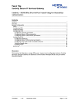
Configuration Guide
Contivity Secure IP Services Gateway
Frame Relay on Contivity Secure IP Services Gateway
Introduction to Frame Relay
Frame relay is a high-speed, packet-switching WAN protocol that connects
geographically dispersed LANs. A public network provider usually offers frame relay.
However, private organizations can acquire and manage their own frame relay networks
as well.
Frame relay is a connection-oriented protocol. This means it relies on end-to-end paths
between devices connected across the network. It implements these connections using
permanent virtual circuits (PVCs).
Frame relay assumes that networks use transmission lines with low error rates, such as
digital transmission media. Therefore, frame relay provides only basic error detection
with no error recovery. This minimizes the processing required for each packet, allowing
frame relay networks to operate at high speeds with few network delays.
Because frame relay performs only basic error checking, end stations running upper-layer
protocols such as the Internet Protocol (IP) are responsible for resending packets that did
not transmit correctly the first time.
Permanent virtual circuits
A permanent virtual circuit (PVC) is a dedicated logical path that connects two devices
over a network. When configured, a PVC is always available to the connected devices; a
PVC does not require setup before data can travel across the network, nor does it need to
be disconnected after data has passed. Because many PVCs can coexist for one physical
line, devices can share the bandwidth of the transmission line.
Frame Relay packets
The structure of a frame relay packet is shown in the following figure.
Figure 1 Frame Relay packet
The packet’s header field includes the following components:
Data link connection identifier (DLCI)
The DLCI is the virtual circuit identification number. The frame relay network uses the
DLCI to direct basic data flow. You configure the DLCI for PVCs.
CG030601
2.00
July 2003
Page: 1 of 14
Configuration Guide
Contivity Secure IP Services Gateway
Frame Relay on Contivity Secure IP Services Gateway
Command/response bit (C/R)
ITU-T (formerly CCITT) standards do not use this bit.
Forward explicit congestion notification (FECN) and backward explicit congestion
notification (BECN)
The FECN and BECN indicate congestion on the network. For information about how the
frame relay software uses these bits, see “Congestion Control”.
Discard eligibility (DE)
The DE bit allows the router to mark specific frames as low priority (discard eligible)
before transmitting them to the frame relay network.
Extended address bit (EA)
The EA bit signals whether the next byte is part of the address. This bit indicates the last
byte of the DLCI.
Management protocols
Frame relay is an access protocol that runs between a CES or data terminal equipment
(DTE) and a switch or data communications equipment (DCE). The CES and the switch
use the Data Link Control Management Interface (DLCMI) to exchange information
about the interface and the status of each virtual circuit.
DLCMI supports three standard data link management specifications: LMI, ANSI T1.617
Annex D, and CCITT (now ITU-T) Q.933 Annex A.
•
•
•
The networking industry first developed the local management interface (LMI)
specification. The LMI approach is asymmetric; the router sends a status-inquiry
message to the network, signaling that the router’s connection to the network is
functioning. The network replies with a status response.
ANSI modified the LMI specification and incorporated it as Annex D to ANSI
standard T1.617. The ANSI method is generally similar to the LMI approach.
The CCITT (now ITU-T) modified the ANSI standard and adopted it as Annex A
to Q.933. The CCITT Annex A specification is similar to Annex D, but it uses an
international numbering scheme.
Be sure to configure the frame relay interface on the CES to use the same management
protocol as the switched network to which it is connected.
CG030601
2.00
July 2003
Page: 2 of 14
Configuration Guide
Contivity Secure IP Services Gateway
Frame Relay on Contivity Secure IP Services Gateway
Address resolution for PVCs
Address resolution for PVCs maps a remote network address such as an IP address to a
local DLCI number. IP uses the Address Resolution Protocol (ARP). ARP dynamically
generates an ARP table of addresses and DLCI numbers by sending messages back and
forth to each network node to gather address information. This process increases
broadcast traffic across the network.
Committed information rate
The committed information rate (CIR) is the rate at which the network supports data
transfer under normal operations. Its name is descriptive: you have a contract with your
carrier, who has committed to providing a given throughput, here called the committed
information rate. The CIR is measured in bits per second. You configure this value that
the carrier provides per virtual circuit.
When configuring the CIR, consider the following:
CIR of 0
You can contract with a carrier for a CIR of 0, which yields best-effort service at low cost.
The carrier transmits data, but does not commit to providing a specified throughput. To
configure a CIR of 0, set both the throughput (which is the CIR) and the committed burst
(Bc) to 0, and set the excess burst (Be) to a value greater than 0. For more information
about burst rates, see the next section, “Committed burst rate and excess burst rate.”
Maximum CIR
The maximum CIR should not be greater than the speed of the access line on the slower
end of a virtual circuit. In a big pipe/little pipe topology likely CIRs at the remote sites
would be 32 Kb/s, 56 Kb/s, or 64 Kb/s. If you configure CIRs for these virtual circuits at
the central site, you can use CIR enforcement (described in the next section) to prevent
the big pipe from sending traffic that exceeds the PVC CIRs.
Committed burst rate and excess burst rate
The committed burst rate (Bc) defines the number of bits that the CES can transmit over a
specified time interval (Tc) when congestion is occurring. The excess burst (Be) defines
the number of extra bits that the CES attempts to send over the Tc when there is no
congestion. Both the Bc and the Be are values that you configure.
The sum of the Bc and the Be is the maximum amount of traffic that can travel across the
network per Tc when there is no congestion. If you set the Be to a value greater than zero,
the CES can send traffic exceeding the CIR. To enforce the CIR, that is, to limit traffic
that the CES can send to the amount of the CIR, set the Be to 0.
CG030601
2.00
July 2003
Page: 3 of 14
Configuration Guide
Contivity Secure IP Services Gateway
Frame Relay on Contivity Secure IP Services Gateway
Congestion control
Network congestion can degrade network performance. Congestion occurs when a node
receives more frames than it can process, or sends more frames than the transmission line
can handle. The frame relay network informs the nodes of congestion so that they can
reduce the amount of traffic across the network.
In the frame relay packet header, there are two bits that the network sets to alert nodes of
network congestion. These bits, as defined by the frame relay specification, are the
forward explicit congestion notation (FECN) bit and the backward explicit congestion
notation (BECN) bit.
If the network detects congestion, it alerts the CES in the same direction as the received
frame by changing the frame’s FECN bit from 0 to 1. For nodes in the opposite direction
of the received frame, it changes the frame’s BECN bit from 0 to 1.
CG030601
2.00
July 2003
Page: 4 of 14
Configuration Guide
Contivity Secure IP Services Gateway
Frame Relay on Contivity Secure IP Services Gateway
Configuring Frame Relay on CES
Configuring frame relay on the CES can be accomplished through the command line
interface (CLI) or through the Web GUI.
To enable Frame Relay through the CLI
1. To configure a physical interface on a slot and connector, navigate to the top-level
box prompt and enter:
Interface serial <slot_number>/<interface_number>
slot_number is the number of the slot on which the link module is located.
interface_number is the number of the module on which the slot is located.
After you configure a physical interface, the CLI returns a prompt that specifies your
current working location.
For example, the following command configures a serial interface on slot 6, interface
1.
CES(config)#interface serial 6/1
CES(config-if)#
2. Configure description and circuit number. The circuit number is only relevant for
administration purposes only. (Not used by system for identification of circuit.)
CES(config-if)#description “frame relay 61”
CES(config-if)#circuit-id 1
3. Configure line rate and interface filter.
CES(config-if)# filter “deny all”
(quotes are needed for filter names with 2 words or more)
CES(config-if)# data-rate 1536
(parameter is entered in kilobits, only valid parameters are multiples of 64k starting at
64k and ending at 2048k)
4. Configure frame-relay connection type with the following command:
Frame-relay connection-type <connection-type>
<connection-type> can be:
direct for placing 2 FR CES ports back-to-back
switched (default) to connection to a frame-relay cloud.
Example:
CES(config-if)#frame-relay connection-type switched
CG030601
2.00
July 2003
Page: 5 of 14
Configuration Guide
Contivity Secure IP Services Gateway
Frame Relay on Contivity Secure IP Services Gateway
Enabling Frame Relay using Web interface
1. Click System->Wan to bring up the following screen:
Figure 2 WAN Interface list screen
2. In the Select column, click the radio button beside the Interface you want to
configure.
3. Click Configure to get the next screen (illustrated in Figure 3).
CG030601
2.00
July 2003
Page: 6 of 14
Configuration Guide
Contivity Secure IP Services Gateway
Frame Relay on Contivity Secure IP Services Gateway
Figure 3 Configure WAN Interface
4. Enter the description and circuit number. The circuit number is only relevant for
administration purposes only. (Not used by system for identification of circuit.)
5. For the Interface Filter field, select the appropriate interface filter from the drop-down
list.
6. For the Protocol field, select Frame Relay Service from the drop-down list.
7. For the Data Rate field, select the appropriate line rate from the drop-down list.
Selecting a management type
You can specify the management protocol that the router and the frame relay network use
to communicate status information. Routers connected back to back also use a
management protocol to exchange status information. The following list describes your
options:
•
DLCMI None provides no management interface between the router and the
frame relay network. In the absence of management support, you must configure
all PVCs manually.
•
Rev 1 LMI provides user-side management services as specified by Revision 1 of
the LMI standard.
CG030601
2.00
July 2003
Page: 7 of 14
Configuration Guide
Contivity Secure IP Services Gateway
Frame Relay on Contivity Secure IP Services Gateway
•
ANSI T1.617D provides user-side management services as specified in Annex-D
to ANSI standard T1.617-1991. This is the default value.
•
CCITT Annex A provides user-side management services as specified by the
ITU-T (formerly CCITT).
Configuring management type using CLI
To specify the link manager type, navigate to the serial interface and enter:
Frame-relay lmi-type <lmi-type>
<lmi-type> can be:
ANSI for ANSIT1.617 Annex D service.
ilmi for Rev. 1 LMI.
none for no management service.
q933a for CCITT Annex A service.
Monitoring the connection
You can monitor the status of your frame relay network connection by setting the time
intervals for the CES to send messages that verify the integrity of the link
Polling interval
The polling interval specifies the amount of time between status inquiry messages that
the CES transmits. Status inquiry messages cause a network to respond with a link
integrity verification message or full status message. Successful completion of the
request/response “handshake” verifies the status of the CES/frame relay network link.
The default polling interval is 10 seconds. If this value does not match what the network
requests, specify a new value in the range of 5 to 30 seconds.
Configuring polling interval using CLI
To configure the polling interval, navigate to the serial interface and enter:
Frame-relay lmi-t391dte <integer>
<integer> is the polling interval, from 5 to 30 seconds. The default is 10.
Full enquiry interval
The full enquiry interval specifies the interval between full status inquiry messages that
the CES transmits. Full status inquiry messages cause the network to send a full status
report message, which lists all PVCs and their status (active or inactive, and new or
previously established). The default full enquiry interval value, 6, tells the CES to send a
full status inquiry every 6 polling intervals. For example, with a polling interval of 10 and
CG030601
2.00
July 2003
Page: 8 of 14
Configuration Guide
Contivity Secure IP Services Gateway
Frame Relay on Contivity Secure IP Services Gateway
a full enquiry interval of 6, the CES transmits a full status inquiry every 60 seconds. With
a polling interval of 20 and a full enquiry interval of 30, the CES transmits a full status
inquiry every 10 minutes (600 seconds).
Using CLI to configure
To configure the full enquiry interval, navigate to the serial interface and enter:
Frame-relay lmi-n391dte <integer>
<integer> is the full enquiry interval, from 1 to 255. The default is 6.
Using Web GUI to configure
To set the connection type, Frame Relay management type, polling interval, and the full
enquiry interval, follow these steps:
1. Bring up the WAN Interface screen (Figure 3), for the interface you are configuring.
2. Click Configure to get the next screen (Figure 4).
Figure 4 Frame Relay Interface screen
3. For the Connection Type field, select Switched if CES connects directly for Frame Relay
switch, or Direct if CES is back to back with another CES.
4. For LMI type field, select Frame Relay management
5. For LMI Poll Interval Timer field, enter the Frame Relay polling interval
6. For LMI Poll Interval Counter field, enter the full enquiry interval.
CG030601
2.00
July 2003
Page: 9 of 14
Configuration Guide
Contivity Secure IP Services Gateway
Frame Relay on Contivity Secure IP Services Gateway
Configuring Frame Relay virtual circuits
You can configure one network/virtual circuit for each Frame Relay DLCI.
Using CLI to configure
Follow these steps to configure a frame relay virtual circuit:
1. Define a virtual circuit.
Frame-relay subinterface <integer>
<integer> is the virtual circuit number, from 1 to 10.
After you configure a virtual circuit number, the CLI returns a prompt that specifies your
current working location. For example, the following command defines virtual circuit 1 on
the frame relay circuit.
CES(config-if)#frame-relay subinterface 1
CES(config-subif)#
2. Add a description for this virtual circuit.
CES(config-subif)#description <virtual-circuit name>
<virtual circuit name> can be any wording used to properly describe this virtual circuit.
Example:
CES(config-subif)# description “virtual circuit1”
3. Define the Frame Relay encapsulation.
CES(config-subif)# encapsulation <encaps_type>
<encaps_type> is the Frame Relay encapsulation type. Currently, the only encaps type
is MPoFR.
Example:
CES(config-subif)#encapsulation MpoFR
4. Define whether the virtual circuit is a public or private interface.
CES(config-subif)#(no) public
By default, the virtual circuit is set to public.
Example on how to change virtual circuit to be a private interface:
CES(config-subif)#no public
Example on how to change virtual circuit to be a public interface.
CES(config-subif)#public
CG030601
2.00
July 2003
Page: 10 of 14
Configuration Guide
Contivity Secure IP Services Gateway
Frame Relay on Contivity Secure IP Services Gateway
5. Define the DLCI number for this virtual circuit.
CES(config-subif)#dlci <integer>
<integer> is the DLCI number for this connection, from 16 – 991.
Example:
CES(config-subif)# dlci 100
6. Configure the traffic shaping parameters, CIR, committed burst, and excess burst.
CES(config-subif)#traffic-shape <CIR> <Committed_Burst>
<Excess_Burst>
<CIR> is the committed information rate assigned to the DLCI, in bits per second.
<Committed_Burst> is the committed burst rate for this DLCI, in bits.
<Excess_Burst> is the excess burst rate for this DLCI, in bits.
Example:
CES(config-subif)#traffic-shape 5000 4000 0
7. Configure the local IP address of this interface.
CES(config-subif)#ip local <address> <mask>
<address> is the IP address for this interface.
<mask> is the subnet mask for this interface.
Example:
CES(config-subif)#ip local 10.1.1.1 255.255.255.0
8. Configure the IP address of device on the remote end of this virtual circuit.
CES(config-subif)#ip remote <address>
<address> is the IP address of the device on the other end of the DLCI.
Example:
CES(config-subif)#ip remote 10.1.1.2
CG030601
2.00
July 2003
Page: 11 of 14
Configuration Guide
Contivity Secure IP Services Gateway
Frame Relay on Contivity Secure IP Services Gateway
Using the Web interface to configure
To configure virtual circuits through the Web interface, follow these steps:
1. Go to the Frame Relay Interface screen, shown in Figure 4.
2. To bring up the Virtual Circuits page (Figure 5), click Configure Virtual Circuits button.
This page lists all virtual circuits that have been configured for this Frame Relay interface.
Figure 5 Frame Relay Virtual Circuits page
3. To add a virtual circuit, click Add, and the following screen appears (Figure 6).
CG030601
2.00
July 2003
Page: 12 of 14
Configuration Guide
Contivity Secure IP Services Gateway
Frame Relay on Contivity Secure IP Services Gateway
Figure 6 Add Virtual Circuit Screen
4. In the VC field, type the virtual circuit number.
5. In the Description field, enter a description of the virtual circuit.
6. From the State menu, select whether this virtual circuit is enabled or disabled.
7. In the Local IP Address field, enter the virtual circuit IP address.
8. In the Subnet Mask field, enter the subnet mask of the IP address.
9. In the Remote IP Address field, enter the IP address of the remote end of this virtual
circuit.
10. In the DLCI field, enter the assigned DLCI number for this virtual circuit.
11. In the CIR field, enter the PVC’s committed information rate.
12. In the Bc field, enter the committed burst for this circuit.
13. In the BE field, enter the excess burst for this circuit.
14. Click OK to create this virtual circuit.
CG030601
2.00
July 2003
Page: 13 of 14
Configuration Guide
Contivity Secure IP Services Gateway
Frame Relay on Contivity Secure IP Services Gateway
Copyright 2003, Nortel Networks. All rights reserved.
*Nortel Networks, the Nortel Networks logo, the Globemark, Unified Networks, and Contivity are
trademarks of Nortel Networks.
Information in this document is subject to change without notice. Nortel Networks assumes no
responsibility for errors that might appear in this document.
If you found this document useful and would like to see more similar documents please send your
feedback to [email protected] with the subject heading "How To Documentation."
If after following this guide you are still having problems please ensure you have carried out the
steps exactly as in this document. You should also check the Nortel Networks FAQs/Solutions
Search Knowledge Database for additional help. If problems still persist, please contact Nortel
Networks Customer Support.
Technical Support Contact Information:
Nortel Networks is committed to bettering the customer experience through its Customer
TouchPoint Program (CTP) – where in most countries one number can be used to contact Nortel
Networks. To obtain regional telephone contact information, please visit the following website:
http://www.nortelnetworks.com/help/contact/global/.
CG030601
2.00
July 2003
Page: 14 of 14