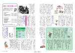
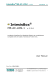
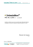
1
TM NHTC NORTEC LINKS 2 OPTIONS Installation Manual Manual No. H-502 2008-02-18 PROPRIETARY NOTICE This document and the information disclosed herein are proprietary data of WALTER MEIER LTD. Neither this document nor the information contained herein shall be reproduced used, or disclosed to others without the written authorization of WALTER MEIER LTD., except to the extent required for installation or maintenance of recipient’s equipment. All references to the NORTEC name should be taken as referring to WALTER MEIER LTD. LIABILITY NOTICE NORTEC does not accept any liability for installations of humidity equipment installed by unqualified personnel or the use of parts/components/equipment that are not authorized or approved by NORTEC. COPYRIGHT NOTICE Copyright 2008, WALTER MEIER LTD. All rights reserved. RECORD OF REVISIONS For each revision, put the revised pages in your manual and discard the superseded pages. Write the revision number and revision date, date put in manual, and the incorporator’s initials in the applicable columns on the Record of Revisions. Revision Number 2008-02-18 Revision Date Date Put In Manual By Revision Number Revision Date Date Put In Manual By TABLE OF CONTENTS Subject Page 10-00 INTRODUCTION 1. OVERVIEW . . . . . . . . . . . . . . . . . . . . . . . . . . . . . . . . . . . . . . . . . . . . . . . . . . . . . . . . . . . . . . . . . . . . . . . . . . . 2 10-10 INSTALLATION PROCEDURES 1. 2. A. B. 3. 4. A. B. 5. NETWORKING . . . . . . . . . . . . . . . . . . . . . . . . . . . . . . . . . . . . . . . . . . . . . . . . . . . . . . . . . . . . . . . . . . . . . . . . . 2 WIRING . . . . . . . . . . . . . . . . . . . . . . . . . . . . . . . . . . . . . . . . . . . . . . . . . . . . . . . . . . . . . . . . . . . . . . . . . . . . . . 3 BACNET/MSTP, JOHNSON N2, AND LONWORKS . . . . . . . . . . . . . . . . . . . . . . . . . . . . . . . . . . . . . . . . 3 BACNET/IP . . . . . . . . . . . . . . . . . . . . . . . . . . . . . . . . . . . . . . . . . . . . . . . . . . . . . . . . . . . . . . . . . . . . . . . . 3 GATEWAY CONFIGURATION. . . . . . . . . . . . . . . . . . . . . . . . . . . . . . . . . . . . . . . . . . . . . . . . . . . . . . . . . . . . . 4 NETWORK INTEGRATION . . . . . . . . . . . . . . . . . . . . . . . . . . . . . . . . . . . . . . . . . . . . . . . . . . . . . . . . . . . . . . . 4 LONWORKS.XIF FILE . . . . . . . . . . . . . . . . . . . . . . . . . . . . . . . . . . . . . . . . . . . . . . . . . . . . . . . . . . . . . . . 4 BACNET PICS AND BIBS. . . . . . . . . . . . . . . . . . . . . . . . . . . . . . . . . . . . . . . . . . . . . . . . . . . . . . . . . . . . . 4 VARIABLE DEFINITION. . . . . . . . . . . . . . . . . . . . . . . . . . . . . . . . . . . . . . . . . . . . . . . . . . . . . . . . . . . . . . . . . . 5 10-20 START-UP 1. 2. NORTEC LINKS 2 START-UP CHECKLIST . . . . . . . . . . . . . . . . . . . . . . . . . . . . . . . . . . . . . . . . . . . . . . . . . . 2 START-UP PROCEDURE . . . . . . . . . . . . . . . . . . . . . . . . . . . . . . . . . . . . . . . . . . . . . . . . . . . . . . . . . . . . . . . . 2 10-30 TROUBLESHOOTING 1. 2. TROUBLESHOOTING . . . . . . . . . . . . . . . . . . . . . . . . . . . . . . . . . . . . . . . . . . . . . . . . . . . . . . . . . . . . . . . . . . 2 INDICATOR LIGHTS . . . . . . . . . . . . . . . . . . . . . . . . . . . . . . . . . . . . . . . . . . . . . . . . . . . . . . . . . . . . . . . . . . . . 2 10-40 SPARE PARTS 1. REPLACEMENT PARTS . . . . . . . . . . . . . . . . . . . . . . . . . . . . . . . . . . . . . . . . . . . . . . . . . . . . . . . . . . . . . . . . . 2 10-50 TECHNICAL 1. WIRING DIAGRAMS . . . . . . . . . . . . . . . . . . . . . . . . . . . . . . . . . . . . . . . . . . . . . . . . . . . . . . . . . . . . . . . . . . . . 2 WARRANTY 2008-02-18 LIST OF FIGURES Figure Page 10-10 INSTALLATION Figure 1. Figure 2. Figure 3. Sample Humidification Applications - Room-Sensed %RH Feedback with Duct Hi-Limit Sensing .16 Sample Humidification Applications - Control Feedback (0-100%) with Duct Hi-Limit Sensing . . . .16 Sample Humidification Applications - 0-10V Signal Directly to Humidifier) . . . . . . . . . . . . . . . . . . .17 10-30 TROUBLESHOOTING Figure 1. Figure 2. Figure 3. Figure 4. OnLine Diagnostic LED Locations . . . . . . . . . . . . . . . . . . . . . . . . . . . . . . . . . . . . . . . . . . . . . . . . . . .3 BACnet Module LED . . . . . . . . . . . . . . . . . . . . . . . . . . . . . . . . . . . . . . . . . . . . . . . . . . . . . . . . . . . . .3 LonWorks Module LED. . . . . . . . . . . . . . . . . . . . . . . . . . . . . . . . . . . . . . . . . . . . . . . . . . . . . . . . . . . .3 Ethernet Port . . . . . . . . . . . . . . . . . . . . . . . . . . . . . . . . . . . . . . . . . . . . . . . . . . . . . . . . . . . . . . . . . . .3 10-40 SPARE PARTS Figure 1. Figure 2. Figure 3. Figure 4. Figure 5. BACnet or N2 Module. . . . . . . . . . . . . . . . . . . . . . . . . . . . . . . . . . . . . . . . . . . . . . . . . . . . . . . . . . . . .3 LonWorks Module. . . . . . . . . . . . . . . . . . . . . . . . . . . . . . . . . . . . . . . . . . . . . . . . . . . . . . . . . . . . . . . .3 OnLine Module . . . . . . . . . . . . . . . . . . . . . . . . . . . . . . . . . . . . . . . . . . . . . . . . . . . . . . . . . . . . . . . . . .3 Ethernet Router . . . . . . . . . . . . . . . . . . . . . . . . . . . . . . . . . . . . . . . . . . . . . . . . . . . . . . . . . . . . . . . . .3 Ethernet Swithch . . . . . . . . . . . . . . . . . . . . . . . . . . . . . . . . . . . . . . . . . . . . . . . . . . . . . . . . . . . . . . . .4 10-50 TECHNICAL Figure 1. Figure 2. Figure 3. Wiring Diagram - NHTC LINKS II BACnet/IP Option . . . . . . . . . . . . . . . . . . . . . . . . . . . . . . . . . . . . .2 Wiring Diagram - NHTC LINKS II LonWorks Option. . . . . . . . . . . . . . . . . . . . . . . . . . . . . . . . . . . . . .3 Wiring Diagram - NHTC LINKS II Option . . . . . . . . . . . . . . . . . . . . . . . . . . . . . . . . . . . . . . . . . . . . . .4 LIST OF TABLES Table Page 10-00 INTRODUCTION Table 1. Protocol Options . . . . . . . . . . . . . . . . . . . . . . . . . . . . . . . . . . . . . . . . . . . . . . . . . . . . . . . . . . . . . . . . .2 10-10 INSTALLATION Table 1. Table 2. Table 3. Table 4. Table 5. Table 6. Table 7. Table 8. Table 9. Table 10. Table 11. Recommended Wire Types and Lengths . . . . . . . . . . . . . . . . . . . . . . . . . . . . . . . . . . . . . . . . . . . . .3 Baud Rates . . . . . . . . . . . . . . . . . . . . . . . . . . . . . . . . . . . . . . . . . . . . . . . . . . . . . . . . . . . . . . . . . . . .4 Variable Definitions. . . . . . . . . . . . . . . . . . . . . . . . . . . . . . . . . . . . . . . . . . . . . . . . . . . . . . . . . . . . . . .6 Variable Addresses Unit #1 . . . . . . . . . . . . . . . . . . . . . . . . . . . . . . . . . . . . . . . . . . . . . . . . . . . . . . . .8 Variable Addresses Unit #2 . . . . . . . . . . . . . . . . . . . . . . . . . . . . . . . . . . . . . . . . . . . . . . . . . . . . . . . .9 Variable Addresses Unit #3 . . . . . . . . . . . . . . . . . . . . . . . . . . . . . . . . . . . . . . . . . . . . . . . . . . . . . . .10 Variable Addresses Unit #4 . . . . . . . . . . . . . . . . . . . . . . . . . . . . . . . . . . . . . . . . . . . . . . . . . . . . . . .11 Variable Addresses Unit #5 . . . . . . . . . . . . . . . . . . . . . . . . . . . . . . . . . . . . . . . . . . . . . . . . . . . . . . .12 Variable Addresses Unit #6 . . . . . . . . . . . . . . . . . . . . . . . . . . . . . . . . . . . . . . . . . . . . . . . . . . . . . . .13 Variable Addresses Unit #7 . . . . . . . . . . . . . . . . . . . . . . . . . . . . . . . . . . . . . . . . . . . . . . . . . . . . . . .14 Variable Addresses Unit #8 . . . . . . . . . . . . . . . . . . . . . . . . . . . . . . . . . . . . . . . . . . . . . . . . . . . . . . .15 10-30 TROUBLESHOOTING Table 1. Table 2. Table 3. OnLine Diagnostic LED Description . . . . . . . . . . . . . . . . . . . . . . . . . . . . . . . . . . . . . . . . . . . . . . . . . .4 LINKS 2 Module Diagnostic LEDs . . . . . . . . . . . . . . . . . . . . . . . . . . . . . . . . . . . . . . . . . . . . . . . . . . .5 Troubleshooting Communication Problems . . . . . . . . . . . . . . . . . . . . . . . . . . . . . . . . . . . . . . . . . . . .6 10-40 SPARE PARTS Table 1. 2008-02-18 Replacement Parts . . . . . . . . . . . . . . . . . . . . . . . . . . . . . . . . . . . . . . . . . . . . . . . . . . . . . . . . . . . . . . .2 THIS PAGE INTENTIONALLY LEFT BLANK 2008-02-18 10-00 INTRODUCTION 10-00 Page 1 2008-02-18 (1) OVERVIEW (1) The NHTC Nortec LINKS 2 Option allows for the integration of a NHTC Series humidifier within a BACnet, Johnson N2 or LonWorks network and allows those units to concurrently be monitored via the Nortec OnLine interface. This option features a Nortec OnLine module co-existing with a gateway that has the capability of converting information from the host Modbus protocol to a specified secondary protocol. (2) The following protocol options are available and must be specified when ordering: Table 1. Protocol Options Protocol Default Baud Rates BACnet MS/TP 38.4 kbps BACnet / IP 10BaseT Johnson N2 9.6 kbps 10-00 Page 2 2008-02-18 10-10 INSTALLATION 10-10 Page 1 2008-02-18 (1) NETWORKING (1) It is possible to network up to a maximum of 8 units to a single LINKS 2. Since each unit is separately addressed, it is possible to monitor and control each unit individually. Different networking configurations may be achieved and are mostly dependant on the type of network present at the site. One networking example could have a Gateway installed inside the lead unit, which could then be daisy-chained to successive units. In turn, the lead unit would connect to a Building Management System (BMS) network via a shielded, twisted-pair connection. Please see wiring section for additional detail. A second example could have a series of units directly connected to an Ethernet network. This is only possible for BACnet communication and is essentially referred to as a BACnet/IP configuration. 10-10 Page 2 2008-02-18 (2) WIRING (A) BACNET/MSTP, JOHNSON N2, AND LONWORKS (1) The necessary internal wiring for the Gateway is already present except for the BMS network connection that can be made via twisted-pair at terminals A and B. To network multiple units to a single Gateway, the units may be daisy-chained to each other using the network link terminals at the TB3 connection jack on the humidifier logic board. Refer to wiring diagram in section 10-50. (1) Table #1 refers to the recommended wire types and maximum recommended lengths from the Nortec LINK 2 module to the front-end of the Building Management system. Since communication between the humidifiers and Nortec Links will always occur via a EIA-485 signal type, Nortec recommends using a 18-24 AWG shielded, twisted pair wire between the lead humidifier and each of the slave humidifiers. Cable runs between the Nortec LINKS 2 module and the furthest slave humidifier should not exceed 2,000 feet. Signal boosters or repeaters may be necessary for longer wire runs or where electrical noise interference is prevalent. Table 1. Recommended Wire Types and Lengths Polarity Protocol Signal Type BACnet MS/TP Johnson N2 EIA-485, 2-wire BACnet/IP LonWorks LAN standard EIA-232, 2-wire A B Net + Net - N/A N/A Tx Rx Recommended Cable 18-24 AWG Shielded, Twisted Pair CAT.5E cable with RJ-45 termination 18-24 AWG Twisted Pair Maximum Recommended Distance from Nortec Module 2300 ft at 9.600 kbps 2000 ft at 38,400 kbps Depends on cable manufacturer Should not exceed 50 ft. (B) BACNET/IP (1) The necessary wiring for the Gateway is present except for the network cable, which must be connected to the RJ-45 (Ethernet) jack on the Gateway. Refer to wiring diagram in section 10-50. 10-10 Page 3 2008-02-18 (3) GATEWAY CONFIGURATION (1) Protocol configuration is made at the factory, prior to final testing. Baud rates are also adjusted to the following values: Table 2. Baud Rates Protocol Default Baud Rates BACnet MS/TP 38.4 kbps BACnet / IP 10BaseT Johnson N2 9.6 kbps (2) For BACnet/IP, BACnet/MSTP and Johnson N2 applications, it is necessary to establish the modules network address parameters in order access it. Address assignments can be configured at the factory or Nortec can provide instructions to modify the address settings in the field. (4) NETWORK INTEGRATION (A) LONWORKS.XIF FILE (1) To facilitate the integration of a LonWorks unit within a network, it may be desirable to obtain an External Interface File (XIF). Files of type .xif are used to convey the resources, specific objects and data types which a LonWorks device possesses. The .xif file allows a network integrator to simulate the presence of a networked humidifier even if it is not yet physically connected to the network. In fact, if the integrator has the .xif files of all network devices, a complete system could be simulated and configured off-line. Once the configuration is done, the integrator's software tool can be connected to the actual system and the configuration information can be downloaded. If a .xif file is required prior to installing a LonWorks-enabled humidifier, please contact the factory to obtain it. (B) BACNET PICS AND BIBS (1) The Protocol Implementation Conformance Statement or “PICS” describes the BACnet capabilities of a particular BACnet implementation. It is a written document, created by the manufacturer of a device, which identifies the particular options specified by BACnet that are implemented in the device. (2) BACnet Interoperability Building Blocks (BIBBs) describe a list of services a BACnet device provides. The main areas that the building blocks are concerned with include: data sharing, trends, schedules, device and system management. BIBBs help specify the interoperability capabilities of a BACnet device. Please contact the factory to obtain a PICS statement or BIBBs profile. 10-10 Page 4 2008-02-18 (5) VARIABLE DEFINITION IMPORTANT: In the variable name, “_x” denotes the humidifier number. If there is only one GSTC humidifier, all variable names will end in “_1”. If two units are networked together (see Figure 4), the second unit’s variable names will end in “_2”. For 3 networked units, “_3” and so on. If unsure of the unit number, each unit will have a label indicating the device instance of each humidifier. If unsure of the unit number, each unit will have a label, in the electrical compartment close to the terminal strip, indicating the device instance of each humidifier. (1) Nortec LINKS 2 monitors a variety of variables for each unit that is connected to it. For a variable listing and definition refer to Table 3. Network variable addresses for the humidifiers may be seen in Table 4 to Table 11. 10-10 Page 5 2008-02-18 Table 3. Variable Definitions R=Read W=Write Description LonWorks SNVT nvoHourOpt_x R Analogue Value Indicates the number of hours the humidifier cylinder has been in operation. SNVT_count_inc nvoCapLimit R Analogue Value Variable Name Reads to capacity limitation applied to the unit output. SNVT_switch (50-100%) nvoRHDem1_x R Analogue Value Reads Ch.1 input signal in %RH or demand to humidifier. (0-100%) SNVT_switch nvoSet1_x R Analogue Value Reads Ch.1 setpoint setting. (10-90%) SNVT_switch nvoRHDem2_x R Analogue Value Reads Ch.2 input signal in %RH or demand to humidifier. (0-100%) Reads Ch.2 setpoint setting. (10-90%) nvoSet2_x R Analogue Value nvoSysDemand_x R Analogue Value Reads humidifier system demand. (0-100%) nviCapLimit R Analogue Value Sets the humidifier’s unit capacity. (50-100%) nviRHDem1_x nviRHDem2_x nviSet1_x nviSet2_x W Analogue Value W Analogue Value W Analogue Value W Analogue Value SNVT_switch Unit must be configured for dual channel operation. Unit must be configured for dual channel operation. Writes Ch.1 demand or %RH level. Allows BMS control of humidifier output. (0-100%) SNVT_switch SNVT_switch SNVT_switch Unit must be configured for networked demand Writes Ch.2 demand or %RH level. Allows BMS control of humidifier output. (0-100%) SNVT_switch Unit must be configured for networked demand Writes Ch.1 setpoint (0-90%) SNVT_switch Writes Ch.2 setpoint (0-90%) SNVT_switch 10-10 Page 6 2008-02-18 Variable Name R=Read W=Write Description Indicates unit fault status. LonWorks SNVT nvoFault_x R Binary Value nvoHWSensor_x R Binary Value nvoNetSensor_x R Binary Value nvoDisable_x R Binary Value nvoSecurity_x R Binary nvoService_x R Binary Value nvoStatus_x R Binary Value Reads humidifier status. 0=standby, 1=humidifying. SNVT_switch nvoConnection_x R Binary Value Indicates that the Nortec Links module is communicating with the Humidifier SNVT_switch nviDisable_x W Binary Value Writes remote disable status. 0=humidifier enabled, 1=humidifier disabled from network SNVT_switch W Binary Value Writes configuration status for network-enabled sensing or control. 0=%RH or %demand input is not from the network 1=%RH or %demand input is from the network SNVT_switch 0=no fault, 1=fault. Indicates if a high-water level condition exists in the humidifier cylinder. 0=normal, 1=high water condition Reads configuration status for network-enabled sensing or control. 0=%RH or %demand input is not from the network 1=%RH or %demand input is from the network Reads remote disable status. 0=humidifier enabled, 1=humidifier disabled by network SNVT_switch SNVT_switch SNVT_switch Indicates security loop status. 0=Sec. loop open, 1=Sec. loop closed SNVT_switch Reads service requirement status. nviNetSensor _x 10-10 Page 7 2008-02-18 0=no service required, 1=service required SNVT_switch Table 4. Humidifier Variable Addresses Unit #1 NHTC LINKS 2 Variable Listing Default BACnet/IP Address: 192.168.10.11; Subnet: 255.255.255.0 Default BACnet/MSTP Address: 78 Default Johnson N2 Address: 174 Unit #1 Variable Name nvoHourOpt_1 nvoCapLimit_1 nvoRHDem1_1 nvoSet1_1 nvoRHDem2_1 nvoSet2_1 nvoSysDemand_1 nviCapLimit_1 nviSet1_1 nviSet2_1 nviRHDem1_1 nviRHDem2_1 nviDisable_1 Expansion_1 Expansion_1 nvoFault_1 nvoHWSensor_1 nvoNetSensor nvoDisable_1 nvoSecurity_1 nvoService_1 nvoStatus_1 Expansion_1 nviNetSensor_1 nvoConnection_1 Expansion_1 Expansion_1 Expansion_1 Expansion_1 Expansion_1 BACnet Type Instance AV 1 AV 2 AV 3 AV 4 AV 5 AV 6 AV 7 AV 8 AV 9 AV 10 AV 11 AV 12 AV 13 AV 14 AV 15 BV BV BV BV BV BV BV BV BV BV BV BV BV BV BV 1 2 3 4 5 6 7 8 9 10 11 12 13 14 15 Lonworks SNVT SNVT # time_hour 124 lev_percent 81 lev_percent 81 lev_percent 81 lev_percent 81 lev_percent 81 lev_percent 81 lev_percent 81 lev_percent 81 lev_percent 81 lev_percent 81 lev_percent 81 switch 95 N/A N/A N/A N/A switch switch switch switch switch switch switch N/A switch switch N/A N/A N/A N/A N/A 95 95 95 95 95 95 95 N/A 95 95 N/A N/A N/A N/A N/A N2 NV Index 1 2 3 4 5 6 7 8 9 10 11 12 20 N/A N/A Type AI AI AI AI AI AI AI AO AO AO AO AO AO AO AO Instance 1 2 3 4 5 6 7 8 9 10 11 12 13 14 15 13 14 15 16 17 18 19 N/A 21 22 N/A N/A N/A N/A N/A Binary In Binary In Binary In Binary In Binary In Binary In Binary In Binary Out Binary Out Binary Out Binary Out Binary Out Binary Out Binary Out Binary Out 1 2 3 4 5 6 7 8 9 10 11 12 13 14 15 10-10 Page 8 2008-02-18 Table 5. Humidifier Variable Addresses Unit #2 Unit #2 Variable Name nvoHourOpt_2 nvoCapLimit_2 nvoRHDem1_2 nvoSet1_2 nvoRHDem1_2 nvoSet2_2 nvoSysDemand_2 nviCapLimit_2 nviSet1_2 nviSet2_2 nviRHDem1_2 nviRHDem2_2 nviDisable_1 Expansion_2 Expansion_2 nvoFault_2 nvoHWSensor_2 nvoNetSensor_2 nvoDisable_2 nvoSecurity_2 nvoService_2 nvoStatus_2 Expansion_2 nviNetSensor_2 nvoConnection_2 Expansion_2 Expansion_2 Expansion_2 Expansion_2 Expansion_2 10-10 Page 9 2008-02-18 BACnet Type Instance AV 16 AV 17 AV 18 AV 19 AV 20 AV 21 AV 22 AV 23 AV 24 AV 25 AV 26 AV 27 AV 28 AV 29 AV 30 BV BV BV BV BV BV BV BV BV BV BV BV BV BV BV 16 17 18 19 20 21 22 23 24 25 26 27 28 29 30 Lonworks SNVT SNVT # time_hour 124 lev_percent 81 lev_percent 81 lev_percent 81 lev_percent 81 lev_percent 81 lev_percent 81 lev_percent 81 lev_percent 81 lev_percent 81 lev_percent 81 lev_percent 81 switch 95 N/A N/A N/A N/A switch switch switch switch switch switch switch N/A switch switch N/A N/A N/A N/A N/A 95 95 95 95 95 95 95 N/A 95 95 N/A N/A N/A N/A N/A N2 NV Index 23 24 25 26 27 28 29 30 31 32 33 34 42 N/A N/A Type AI AI AI AI AI AI AI AO AO AO AO AO AO AO AO Instance 16 17 18 19 20 21 22 23 24 25 26 27 28 29 30 35 36 37 38 39 40 41 N/A 43 44 N/A N/A N/A N/A N/A Binary In Binary In Binary In Binary In Binary In Binary In Binary In Binary Out Binary Out Binary Out Binary Out Binary Out Binary Out Binary Out Binary Out 16 17 18 19 20 21 22 23 24 25 26 27 28 29 30 Table 6. Humidifier Variable Addresses Unit #3 Unit #3 Variable Name nvoHourOpt_3 nvoCapLimit_3 nvoRHDem1_3 nvoSet1_3 nvoRHDem1_3 nvoSet2_3 nvoSysDemand_3 nviCapLimit_3 nviSet1_3 nviSet2_3 nviRHDem1_3 nviRHDem2_3 nviDisable_3 Expansion_3 Expansion_3 nvoFault_3 nvoHWSensor_3 nvoNetSensor_3 nvoDisable_3 nvoSecurity_3 nvoService_3 nvoStatus_3 Expansion_2 nviNetSensor_3 nvoConnection_3 Expansion_3 Expansion_3 Expansion_3 Expansion_3 Expansion_3 BACnet Type Instance AV 31 AV 32 AV 33 AV 34 AV 35 AV 36 AV 37 AV 38 AV 39 AV 40 AV 41 AV 42 AV 43 AV 44 AV 45 BV BV BV BV BV BV BV BV BV BV BV BV BV BV BV 31 32 33 34 35 36 37 38 39 40 41 42 43 44 45 Lonworks SNVT SNVT # time_hour 124 lev_percent 81 lev_percent 81 lev_percent 81 lev_percent 81 lev_percent 81 lev_percent 81 lev_percent 81 lev_percent 81 lev_percent 81 lev_percent 81 lev_percent 81 switch 95 N/A N/A N/A N/A switch switch switch switch switch switch switch N/A switch switch N/A N/A N/A N/A N/A 95 95 95 95 95 95 95 N/A 95 95 N/A N/A N/A N/A N/A N2 Element 45 46 47 48 49 50 51 52 53 54 55 56 64 N/A N/A Type AI AI AI AI AI AI AI AO AO AO AO AO AO AO AO Instance 31 32 33 34 35 36 37 38 39 40 41 42 43 44 45 57 58 59 60 61 62 63 N/A 65 66 N/A N/A N/A N/A N/A Binary In Binary In Binary In Binary In Binary In Binary In Binary In Binary Out Binary Out Binary Out Binary Out Binary Out Binary Out Binary Out Binary Out 31 32 33 34 35 36 37 38 39 40 41 42 43 44 45 10-10 Page 10 2008-02-18 Table 7. Humidifier Variable Addresses Unit #4 Unit #4 Variable Name nvoHourOpt_4 nvoCapLimit_4 nvoRHDem1_4 nvoSet1_4 nvoRHDem1_4 nvoSet2_4 nvoSysDemand_4 nviCapLimit_4 nviSet1_4 nviSet2_4 nviRHDem1_4 nviRHDem2_4 nviDisable_4 Expansion_4 Expansion_4 nvoFault_4 nvoHWSensor_4 nvoNetSensor_4 nvoDisable_4 nvoSecurity_4 nvoService_4 nvoStatus_4 Expansion_2 nviNetSensor_4 nvoConnection_4 Expansion_4 Expansion_4 Expansion_4 Expansion_4 Expansion_4 10-10 Page 11 2008-02-18 BACnet Type Instance AV 46 AV 47 AV 48 AV 49 AV 50 AV 51 AV 52 AV 53 AV 54 AV 55 AV 56 AV 57 AV 58 AV 59 AV 60 BV BV BV BV BV BV BV BV BV BV BV BV BV BV BV 46 47 48 49 50 51 52 53 54 55 56 57 58 59 60 Lonworks SNVT SNVT # time_hour 124 lev_percent 81 lev_percent 81 lev_percent 81 lev_percent 81 lev_percent 81 lev_percent 81 lev_percent 81 lev_percent 81 lev_percent 81 lev_percent 81 lev_percent 81 switch 95 N/A N/A N/A N/A switch switch switch switch switch switch switch N/A switch switch N/A N/A N/A N/A N/A 95 95 95 95 95 95 95 N/A 95 95 N/A N/A N/A N/A N/A N2 Element 67 68 69 70 71 72 73 74 75 76 77 78 86 N/A N/A Type AI AI AI AI AI AI AI AO AO AO AO AO AO AO AO Instance 46 47 48 49 50 51 52 53 54 55 56 57 58 59 60 79 80 81 82 83 84 85 N/A 87 88 N/A N/A N/A N/A N/A Binary In Binary In Binary In Binary In Binary In Binary In Binary In Binary Out Binary Out Binary Out Binary Out Binary Out Binary Out Binary Out Binary Out 46 47 48 49 50 51 52 53 54 55 56 57 58 59 60 Table 8. Humidifier Variable Addresses Unit #5 Unit #5 Variable Name nvoHourOpt_5 nvoCapLimit_5 nvoRHDem1_5 nvoSet1_5 nvoRHDem1_5 nvoSet2_5 nvoSysDemand_5 nviCapLimit_5 nviSet1_5 nviSet2_5 nviRHDem1_5 nviRHDem2_5 nviDisable_5 Expansion_5 Expansion_5 nvoFault_5 nvoHWSensor_5 nvoNetSensor_5 nvoDisable_5 nvoSecurity_5 nvoService_5 nvoStatus_5 Expansion_2 nviNetSensor_5 nvoConnection_5 Expansion_5 Expansion_5 Expansion_5 Expansion_5 Expansion_5 BACnet Type Instance AV 61 AV 62 AV 63 AV 64 AV 65 AV 66 AV 67 AV 68 AV 69 AV 70 AV 71 AV 72 AV 73 AV 74 AV 75 BV BV BV BV BV BV BV BV BV BV BV BV BV BV BV 61 62 63 64 65 66 67 53 69 70 71 72 73 74 75 Lonworks SNVT SNVT # time_hour 124 lev_percent 81 lev_percent 81 lev_percent 81 lev_percent 81 lev_percent 81 lev_percent 81 lev_percent 81 lev_percent 81 lev_percent 81 lev_percent 81 lev_percent 81 switch 95 N/A N/A N/A N/A switch switch switch switch switch switch switch N/A switch switch N/A N/A N/A N/A N/A 95 95 95 95 95 95 95 N/A 95 95 N/A N/A N/A N/A N/A N2 Element 89 90 91 92 93 94 95 96 97 98 99 100 108 N/A N/A Type AI AI AI AI AI AI AI AO AO AO AO AO AO AO AO Instance 61 62 63 64 65 66 67 68 69 70 71 72 73 74 75 101 102 103 104 105 106 107 N/A 109 110 N/A N/A N/A N/A N/A Binary In Binary In Binary In Binary In Binary In Binary In Binary In Binary Out Binary Out Binary Out Binary Out Binary Out Binary Out Binary Out Binary Out 61 62 63 64 65 66 67 68 69 70 71 72 73 74 75 10-10 Page 12 2008-02-18 Table 9. Humidifier Variable Addresses Unit #6 Unit #6 Variable Name nvoHourOpt_6 nvoCapLimit_6 nvoRHDem1_6 nvoSet1_6 nvoRHDem1_6 nvoSet2_6 nvoSysDemand_6 nviCapLimit_6 nviSet1_6 nviSet2_6 nviRHDem1_6 nviRHDem2_6 nviDisable_6 Expansion_6 Expansion_6 nvoFault_6 nvoHWSensor_6 nvoNetSensor_6 nvoDisable_6 nvoSecurity_6 nvoService_6 nvoStatus_6 Expansion_6 nviNetSensor_6 nvoConnection_6 Expansion_6 Expansion_6 Expansion_6 Expansion_6 Expansion_6 10-10 Page 13 2008-02-18 BACnet Type Instance AV 76 AV 77 AV 78 AV 79 AV 80 AV 81 AV 82 AV 83 AV 84 AV 85 AV 86 AV 87 AV 88 AV 89 AV 90 BV BV BV BV BV BV BV BV BV BV BV BV BV BV BV 76 77 78 79 80 81 82 83 84 85 86 87 88 89 90 Lonworks SNVT SNVT # time_hour 124 lev_percent 81 lev_percent 81 lev_percent 81 lev_percent 81 lev_percent 81 lev_percent 81 lev_percent 81 lev_percent 81 lev_percent 81 lev_percent 81 lev_percent 81 switch 95 N/A N/A N/A N/A switch switch switch switch switch switch switch N/A switch switch N/A N/A N/A N/A N/A 95 95 95 95 95 95 95 N/A 95 95 N/A N/A N/A N/A N/A N2 Element 111 112 113 114 115 116 117 118 119 120 121 122 130 N/A N/A Type AI AI AI AI AI AI AI AO AO AO AO AO AO AO AO Instance 76 77 78 79 80 81 82 83 84 85 86 87 88 89 90 123 124 125 126 127 128 129 N/A 131 132 N/A N/A N/A N/A N/A Binary In Binary In Binary In Binary In Binary In Binary In Binary In Binary Out Binary Out Binary Out Binary Out Binary Out Binary Out Binary Out Binary Out 76 77 78 79 80 81 82 83 84 85 86 87 88 89 90 Table 10. Humidifier Variable Addresses Unit #7 Unit #7 Variable Name nvoHourOpt_7 nvoCapLimit_7 nvoRHDem1_7 nvoSet1_7 nvoRHDem1_7 nvoSet2_7 nvoSysDemand_7 nviCapLimit_7 nviSet1_7 nviSet2_7 nviRHDem1_7 nviRHDem2_7 nviDisable_7 Expansion_7 Expansion_7 nvoFault_7 nvoHWSensor_7 nvoNetSensor_7 nvoDisable_7 nvoSecurity_7 nvoService_7 nvoStatus_7 Expansion_7 nviNetSensor_7 nvoConnection_7 Expansion_7 Expansion_7 Expansion_7 Expansion_7 Expansion_7 BACnet Type Instance AV 91 AV 92 AV 93 AV 94 AV 95 AV 96 AV 97 AV 98 AV 99 AV 100 AV 101 AV 102 AV 103 AV 104 AV 105 BV BV BV BV BV BV BV BV BV BV BV BV BV BV BV 91 92 93 94 95 96 97 98 99 100 101 102 103 104 105 Lonworks SNVT SNVT # time_hour 124 lev_percent 81 lev_percent 81 lev_percent 81 lev_percent 81 lev_percent 81 lev_percent 81 lev_percent 81 lev_percent 81 lev_percent 81 lev_percent 81 lev_percent 81 switch 95 N/A N/A N/A N/A switch switch switch switch switch switch switch N/A switch switch N/A N/A N/A N/A N/A 95 95 95 95 95 95 95 N/A 95 95 N/A N/A N/A N/A N/A N2 Element 133 134 135 136 137 138 139 140 141 142 143 144 152 N/A N/A Type AI AI AI AI AI AI AI AO AO AO AO AO AO AO AO Instance 91 92 93 94 95 96 97 98 99 100 101 102 103 104 105 145 146 147 148 149 150 151 N/A 153 154 N/A N/A N/A N/A N/A Binary In Binary In Binary In Binary In Binary In Binary In Binary In Binary Out Binary Out Binary Out Binary Out Binary Out Binary Out Binary Out Binary Out 91 92 93 94 95 96 97 98 99 100 101 102 103 104 105 10-10 Page 14 2008-02-18 Table 11. Humidifier Variable Addresses Unit #8 Unit #8 Variable Name nvoHourOpt_8 nvoCapLimit_8 nvoRHDem1_8 nvoSet1_8 nvoRHDem1_8 nvoSet2_8 nvoSysDemand_8 nviCapLimit_8 nviSet1_8 nviSet2_8 nviRHDem1_8 nviRHDem2_8 nviDisable_8 Expansion_8 Expansion_8 nvoFault_8 nvoHWSensor_8 nvoNetSensor_8 nvoDisable_8 nvoSecurity_8 nvoService_8 nvoStatus_8 Expansion_8 nviNetSensor_8 nvoConnection_8 Expansion_8 Expansion_8 Expansion_8 Expansion_8 Expansion_8 10-10 Page 15 2008-02-18 BACnet Type Instance AV 106 AV 107 AV 108 AV 109 AV 110 AV 111 AV 112 AV 113 AV 114 AV 115 AV 116 AV 117 AV 118 AV 119 AV 120 BV BV BV BV BV BV BV BV BV BV BV BV BV BV BV 106 107 108 109 110 111 112 116 114 115 116 117 118 119 120 Lonworks SNVT SNVT # time_hour 124 lev_percent 81 lev_percent 81 lev_percent 81 lev_percent 81 lev_percent 81 lev_percent 81 lev_percent 81 lev_percent 81 lev_percent 81 lev_percent 81 lev_percent 81 switch 95 N/A N/A N/A N/A switch switch switch switch switch switch switch N/A switch switch N/A N/A N/A N/A N/A 95 95 95 95 95 95 95 N/A 95 95 N/A N/A N/A N/A N/A N2 Element 155 156 157 158 159 160 161 162 163 164 165 166 174 N/A N/A Type AI AI AI AI AI AI AI AO AO AO AO AO AO AO AO Instance 106 107 108 109 110 111 112 113 114 115 116 117 118 119 120 167 168 169 170 171 172 173 N/A 175 176 N/A N/A N/A N/A N/A Binary In Binary In Binary In Binary In Binary In Binary In Binary In Binary Out Binary Out Binary Out Binary Out Binary Out Binary Out Binary Out Binary Out 106 107 108 109 110 111 112 113 114 115 116 117 118 119 120 Configuration Variables nviInputType_x = 1 nviNetSensor_x = 1 Control Variables nviSet1_x = Room Setpoint (0-100%) nviSet2_x = Hi-Limit Setpoint (0-100%) nviRHDem1_x = Room %RH (0-100%) nviRHDem2_x = Hi-Limit %RH (0-100%) nviDisable_x = 1 Unit Disabled = 0 Unit Enabled Readable Variables nvoStatus_x = 1 Humidifying = 0 Standby nvoService_x = 1 Service Required = 0 No Service Required nvoFault_x = 1 Fault = 0 No Fault nvoSysDemand_x = System Demand(0-100%) nvoDisable_x = 1 Unit Disabled = 0 Unit Enabled NHTC Figure 1. Sample Humidification Applications Room-Sensed %RH Feedback with Duct Hi-Limit Sensing Configuration Variables nviInputType_x = 0 nviNetSensor_x = 1 Control Variables nviSet1_x = Room Setpoint (0-100%) nviSet2_x = Hi-Limit Setpoint (0-100%) nviRHDem1_x = Room %RH (0-100%) nviRHDem2_x = Hi-Limit %RH (0-100%) nviDisable_x = 1 Unit Disabled = 0 Unit Enabled Readable Variables nvoStatus_x = 1 Humidifying = 0 Standby nvoService_x = 1 Service Required = 0 No Service Required nvoFault_x = 1 Fault = 0 No Fault nvoSysDemand_x = System Demand(0-100%) nvoDisable_x = 1 Unit Disabled = 0 Unit Enabled NHTC Figure 2. Sample Humidification Applications Control Feedback (0-100%) with Duct Hi-Limit Sensing 10-10 Page 16 2008-02-18 Configuration Variables nviInputType_x = 1 nviNetSensor_x = 0 Control Variables nviSet1_x = Room Setpoint (0-100%) nviSet2_x = Hi-Limit Setpoint (0-100%) nviRHDem1_x = Room %RH (0-100%) nviRHDem2_x = Hi-Limit %RH (0-100%) nviDisable_x = 1 Unit Disabled = 0 Unit Enabled Readable Variables nvoStatus_x = 1 Humidifying = 0 Standby nvoService_x = 1 Service Required = 0 No Service Required nvoFault_x = 1 Fault = 0 No Fault nvoSysDemand_x = System Demand(0-100%) nvoDisable_x = 1 Unit Disabled = 0 Unit Enabled NHTC Figure 3. Sample Humidification Applications Room-Sensed %RH Feedback with Duct Hi-Limit Sensing (0-10V Signal Directly to Humidifier) 10-10 Page 17 2008-02-18 THIS PAGE INTENTIONALLY LEFT BLANK 10-10 Page 18 2008-02-18 10-20 START-UP 10-20 Page 1 2008-02-18 (1) NORTEC LINKS 2 START-UP CHECKLIST WIRING Humidifier-to-Humidifier Connection: Each individual humidifier linked to lead unit. Connection must be daisy-chained to other units. BMS Network Connection: Lead unit wired to BMS system (Twisted Pair or Ethernet). Network activity verified. Controls Wired: Directly to humidifiers or through BMS network. (2) START-UP PROCEDURE (1) Ensure power is being supplied to the humidifier, Nortec Links Module and Nortec OnLine module. For BACnet/IP adjust network IP settings. (If this information is provided, factory will perform necessary IP assignment). (2) After power-up, verify network communication. (3) Map desired network variables to BMS. (4) Verify variable operation after mapping is complete. (5) Perform regular humidifier start-up check. 10-20 Page 2 2008-02-18 10-30 TROUBLESHOOTING 10-30 Page 1 2008-02-18 (1) TROUBLESHOOTING (1) When troubleshooting the communication process for OnLine and/or LINKS 2 modules should be kept in mind. Humidifier data is first received by the Nortec OnLine module using the modbus protocol over the serial port connection. It then forwards this data, via modbus/TCP, to the LINKS 2 module over an Ethernet link. A router (switch for BACnet/IP applications) links the two devices together through their Ethernet ports and allows a user to access both devices using only 1 customer installed Ethernet line. (2) INDICATOR LIGHTS (1) There is a variety of status LEDs on both the OnLine module and the LINKS 2 module to aid in the diagnosis of communication problems. Note that communication first occurs between the OnLine module and the humidifier logic board. The OnLine module then passes information to the LINKS 2 module. If practical, it may be useful to establish a connection with the Nortec OnLine server first and then establish communication with the LINKS 2 module. 10-30 Page 2 2008-02-18 Module Status RX – Receive LED Serial Port Activity Power LED Ethernet Activity Ethernet Link TX – Transmit LED Figure 1. OnLine Diagnostic LED Locations Figure 2. BACnet Module LED Lon Device Status RX – Receive LED Power LED Ethernet Activity Ethernet LINKS 2 TX – Transmit LED Figure 3. LonWorks Module LED 10-30 Page 3 2008-02-18 Figure 4. Ethernet Port Table 1. OnLine Diagnostic LED Description LED Name Module Status Serial Port Activity Ethernet Activity/Collision Ethernet Link Color Function Off Indicates that the Online module is not receiving power. Green Indicates the Online module is operating normally. Orange Indicates that the Online module is loading the firmware installed on the module. Flashing Green Indicates that the Online module is receiving a network packet from a serial connection. Flashing Red Indicates that the Online module is transmitting a network packet on a serial connection. Orange Displayed when the Online module is booting. Flashing Green Indicates that the Online module is receiving a network packet from an Ethernet connection. Flashing Red Indicates that the Online module is transmitting a network packet on an Ethernet connection. Off No network connection is present. Green The Online module has detected the presence of a 10Mbps network. Orange The Online module has detected the presence of a 100Mbps network. 10-30 Page 4 2008-02-18 Table 2. LINKS 2 Module Diagnostic LEDs LED Name Color Function Module Power Off Indicates that the Online module is not receiving power. Green Indicates the Online module is operating normally. Receive LED (marked as Rx on processor board) Flashing Green Indicates that the Online module is receiving a network packet from a serial connection. Transmit LED (marked as Tx on processor board) Flashing Green Indicates that the Online module is transmitting a network packet on a serial connection. Ethernet LINK Off Indicates no Ethernet connection is present. Solid Yellow Indicates an Ethernet connection has been detected. Off No Ethernet network activity. Flashing Green Indicates Ethernet activity. Ethernet Activity 10-30 Page 5 2008-02-18 Table 3. Troubleshooting Communication Problems Problem 1. The BMS network cannot read/write any information to any of the networked humidifiers Solution Verify that the network connection is made and is connected properly. Verify that the correct network settings are being used. The LINKS 2 module may need to be restarted to load the new settings. Check the Serial Port Activity LED on the Nortec OnLine module to ensure proper communication with the humidifiers. Data is first received from the humidifier to the OnLine module. The OnLine module then transmits this data, via the Ethernet port, to the LINKS 2 module. Check the Ethernet port activity on the LINKS 2 module to ensure it is receiving data from the Nortec OnLine module. Check the transmit and receive status LEDs to determine if there is any network traffic being sent or being received by the LINKS 2 module from the BMS network Verify proper connections to networked humidifiers. Turn the LINKS 2 module and the OnLine module off for several seconds then switch it back on to reload the control program. Allow for some time for the network variables to be polled. 2. The BMS network can see some of the networked humidifiers but not others. Ensure network variables are mapped correctly to the BMS. Ensure proper connections to the humidifiers. Disconnect all of the humidifiers from the LINKS 2 package except for the unit that is not responding to the network. Turn the LINKS 2 package off and then back on. Check if the humidifier can now be seen by the BMS 3. The BMS network receives information from the networked humidifier(s) but the information is mismatched or the humidifier responds un-expectedly Verify that the network variables have been mapped to the BMS network correctly. It is possible that the variables have been cross-linked during the network integration process. 4. After sending the humidifier a network-based demand signal the unit powers down after several minutes. The nviNetSensor variable is switched on and a value has been set for the nviRHDem1 variable. When a BMS network demand/RH signal is being used the network must refresh the nviRHDem signal at least every 5 minutes otherwise the humidifier will revert to a 0 demand state. This is a safety precaution in case the BMS network connection is lost. Connect humidifiers one at a time and test units individually. 10-30 Page 6 2008-02-18 10-40 SPARE PARTS 10-40 Page 1 2008-02-18 Table 1. Replacement Parts Nortec LINKS 2 Options Part Number Description Specify Unit Type Protocol at time of order BACnet/MSTP 2527101 LINKS 2 Replacement Module, BACnet/IP 2527102 LINKS 2 Replacement Module, BACnet/MSTP 2527103 LINKS 2 Replacement Module, LonWorks 2527104 LINKS 2 Replacement Module, N2 1509604 OnLine Replacement Module, Static/IP X 2528126 LINKS 2 Replacement Router X 2531455 LINKS 2 Ethernet Switch 2530087 24VAV to 9VDC Power Supply (for switch or router) BACnet/IP N2 LonWorks X X X X X X X X X X X X X X 10-40 Page 2 2008-02-18 Figure 1. BACnet or N2 Module Figure 2. LonWorks Module Figure 3. OnLine Module Figure 4. Ethernet Router 10-40 Page 3 2008-02-18 Figure 5. Ethernet Switch 10-40 Page 4 2008-02-18 10-50 TECHNICAL 10-50 Page 1 2008-02-18 To Units 2 to 8 A B Nortec LINKS 2 Terminal Strip (Unit 1) Shield Net Net + External wiring ‘by others’ - 18 to 24 AWG stranded - Twisted pair, shielded External Internal J5 1 RJ-45 RJ-12 J3 Nortec OnLine Module NHTC Processor Board J4 Nortec LINKS 2 Module RJ-45 J1 EIA-232 Serial Port J2 DC Power Supply 9 VDC Input +9V on center pin 1 2 3 4 5 LAN Ports 5-Port Ethernet Switch 24 VAC HOT AC GND DC GND 9 VDC OUT Note: Use open LAN port when employing an internet connection for BACnet/IP and/or Nortec OnLine. WID NHTC LINKS 2 BACnet/IP Option Supplemental Wiring Diagram Diagram No. 2531457 Rev. B Aug 22, 2007 Figure 1. Wiring Diagram 10-50 Page 2 2008-02-18 External wiring ‘by others’ - 18 to 24 AWG stranded - Twisted pair, shielded To BMS Network A B Nortec LINKS 2 Terminal Strip (Unit 1) Shield Net Net + To Units 2 to 8 External Internal J5 1 RJ-45 RJ-12 J3 Nortec OnLine Module NHTC Processor Board J4 Nortec LINKS 2 Module RJ-45 J1 EIA-232 Serial Port J2 LonWorks Service Pin DC Power Supply 9 VDC Input +9V on center pin 1 2 3 4 LAN Ports 24 VAC HOT 4-Port Router AC GND WAN Port DC GND 9 VDC OUT Note: Use Router WAN port when employing an internet connection for OnLine. Use A and B terminals for LonWorks feedback. WID NHTC LINKS 2 LonWorks Option Supplemental Wiring Diagram Diagram No. 2531433 Rev. B Figure 2. Wiring Diagram 10-50 Page 3 2008-02-18 Aug 21, 2007 External wiring ‘by others’ - 18 to 24 AWG stranded - Twisted pair, shielded To BMS Network A B Shield Net Net + Nortec LINKS 2 Terminal Strip (Unit 1) To Units 2 to 13 External Internal J5 1 RJ-12 J3 Nortec LINKS 2 Module Nortec OnLine Module NHTC Processor Board RJ-45 RJ-45 EIA-232 Serial Port J4 J1 J2 DC Power Supply 9 VDC Input +9V on center pin 1 2 3 4 LAN Ports 24 VAC HOT 4-Port Router AC GND WAN Port DC GND 9 VDC OUT User Interface Ports Note: Use Router WAN port when employing an internet connection for OnLine. Use A and B terminals for Johnson N2 and BACnet/MSTP feedback. Customer Internet Connection (OnLine Interface) WID NHTC Nortec LINKS 2 Option Supplemental Wiring Diagram Diagram No. 2525757 Rev. A Aug 1, 2007 Figure 3. Wiring Diagram 10-50 Page 4 2008-02-18 THIS PAGE INTENTIONALLY LEFT BLANK 10-50 Page 5 2008-02-18 WARRANTY (1) WALTER MEIER INC. and/or WALTER MEIER LTD. (hereinafter collectively referred to as THE COMPANY), warrant for a period of two years after installation or 30 months from manufacturer’s ship date, whichever date is earlier, that THE COMPANY’s manufactured and assembled products, not otherwise expressly warranted (with the exception of the cylinder), are free from defects in material and workmanship. No warranty is made against corrosion, deterioration, or suitability of substituted materials used as a result of compliance with government regulations. (2) THE COMPANY’s obligations and liabilities under this warranty are limited to furnishing replacement parts to the customer, F.O.B. THE COMPANY’s factory, providing the defective part(s) is returned freight prepaid by the customer. Parts used for repairs are warranted for the balance of the term of the warranty on the original humidifier or 90 days, whichever is longer. (3) The warranties set forth herein are in lieu of all other warranties expressed or implied by law. No liability whatsoever shall be attached to THE COMPANY until said products have been paid for in full and then said liability shall be limited to the original purchase price for the product. Any further warranty must be in writing, signed by an officer of THE COMPANY. (4) THE COMPANY’s limited warranty on accessories, not of the companies manufacture, such as controls, humidistats, pumps, etc. is limited to the warranty of the original equipment manufacturer from date of original shipment of humidifier. (5) THE COMPANY makes no warranty and assumes no liability unless the equipment is installed in strict accordance with a copy of the catalog and installation manual in effect at the date of purchase and by a contractor approved by THE COMPANY to install such equipment. (6) THE COMPANY makes no warranty and assumes no liability whatsoever for consequential damage or damage resulting directly from misapplication, incorrect sizing or lack of proper maintenance of the equipment. (7) THE COMPANY retains the right to change the design, specification and performance criteria of its products without notice or obligation. INSTALLATION DATE (MM/DD/YYYY) MODEL # SERIAL # U.S.A. Walter Meier (Climate USA) Inc. CANADA Walter Meier (Climate Canada) Ltd. 826 Proctor Avenue Ogdensburg, NY 13669 TEL: 1-866-NORTEC-1 EMAIL: [email protected] WEBSITE: www.humidity.com 2740 Fenton Road Ottawa, ON K1T 3T7 TEL: 1-866-NORTEC-1 FAX: (613) 822-7964 Authorized Agent: