1
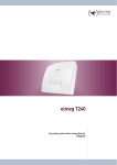
Orion 2000
Cable Router
User’s Guide
Rev. 1.2c
Firmware 2.59.2013
Oct 20th, 2003
Contents
1. BEFORE YOU BEGIN ...........................................................................................................5
Understand the Cable Modem’s Features ....................................................................................................... 5
Contact Your Local Cable Operator ................................................................................................................ 5
Prepare Your Area for Cable Modem Installation.......................................................................................... 6
Gather Supplied and Required Items .............................................................................................................. 6
2. INSTALLING THE CABLE MODEM USING THE USB PORT ....................................7
Installing the Hardware .................................................................................................................................. 10
Installing the Software Drivers....................................................................................................................... 10
Installing the Software Drivers in Windows 98 SE Operating System ....................................................... 10
Installing the Software Drivers in Windows Me Operating System............................................................ 16
Installing the Software Drivers in Windows 2000 Operating System ......................................................... 19
Installing the Software Drivers in Windows XP Operating System ............................................................ 23
Troubleshooting the USB Installation............................................................................................................ 25
Uninstalling the USB Driver ........................................................................................................................... 26
3. INSTALLING THE MODEM USING THE ETHERNET PORT...................................27
Installing the Hardware .................................................................................................................................. 27
Troubleshooting the Ethernet Installation..................................................................................................... 28
4. CABLE MODEM LEDS AND CONNECTORS ...............................................................30
LEDs on the Front of the Modem................................................................................................................... 30
Connectors on the Back of the Modem.......................................................................................................... 31
5. TELNET COMMANDS.......................................................................................................32
Debug................................................................................................................................................................ 34
Undebug............................................................................................................................................................ 34
User’ Guide
2
Image ................................................................................................................................................................ 35
Ping ................................................................................................................................................................... 35
Tracert .............................................................................................................................................................. 36
Password........................................................................................................................................................... 36
User-Level......................................................................................................................................................... 36
Show.................................................................................................................................................................. 37
NVRAM............................................................................................................................................................ 45
TFTP................................................................................................................................................................. 45
Host-name ........................................................................................................................................................ 45
DHCP................................................................................................................................................................ 46
NAT................................................................................................................................................................... 48
One to one mapping .............................................................................................................................. 48
Port forwarding setting ........................................................................................................................ 49
NAT static ip.......................................................................................................................................... 50
NAT static gateway ............................................................................................................................... 50
Interfaces .......................................................................................................................................................... 51
IP ....................................................................................................................................................................... 54
RIP .................................................................................................................................................................... 54
Web-access........................................................................................................................................................ 55
Telnet-access..................................................................................................................................................... 56
Access-list ......................................................................................................................................................... 56
PPPoE-Forwarding ......................................................................................................................................... 57
Copy.................................................................................................................................................................. 57
Clear ................................................................................................................................................................. 57
CPE-limit.......................................................................................................................................................... 57
SNMP................................................................................................................................................................ 58
NSA ................................................................................................................................................................... 58
Line ................................................................................................................................................................... 58
Wirte ................................................................................................................................................................. 58
User’ Guide
3
Reset.................................................................................................................................................................. 58
Quit ................................................................................................................................................................... 58
6. MODE OF OPERATION .....................................................................................................59
Bridge mode ..................................................................................................................................................... 59
NAT mode......................................................................................................................................................... 59
Routing mode ................................................................................................................................................... 60
NAT/Routing mode.......................................................................................................................................... 61
7. WEB USER INTERFACE ....................................................................................................62
Accessing the Web User Interface .................................................................................................................. 62
Web User Interface Home Page...................................................................................................................... 62
Cable Modem Information ............................................................................................................................. 63
Cable Modem Status........................................................................................................................................ 64
Downstream ..................................................................................................................................................... 65
Upstream .......................................................................................................................................................... 66
Upstream Burst................................................................................................................................................ 67
Operation Parameters ..................................................................................................................................... 68
Event Log ......................................................................................................................................................... 69
Router/NAT configuration .............................................................................................................................. 70
Bridge Mode .......................................................................................................................................... 70
NAT Mode.............................................................................................................................................. 71
Router Mode.......................................................................................................................................... 72
NAT Router Mode................................................................................................................................. 75
DHCP................................................................................................................................................................ 79
9. DOCSIS CONFIGURATION FILE VSIF TAG SUPPORT ............................................81
User’ Guide
4
1. Before You Begin
Your new cable modem provides high-speed access to the Internet by an active Internet Connection
through your cable service provider. This user guide describes how to set up and use the cable
modem. Before installing the cable modem, you should read this user guide to ensure proper cable
modem operation.
Understand the Cable Modem’s Features
Your cable modem has the following features to help you access and use the Internet:
•
Two-way design allows the cable modem to send and receive data over the cable television
network.
•
Cable bandwidth allows data rates of up to 38 megabits per second (Mbps)*, which is faster
than analog modems, integrated services digital network (ISDN), or asymmetric digital
subscriber line (ADSL).
•
Using your cable line means that the cable modem is always on, always connected, and does
not tie up your phone line.
•
Plug-and-play operation through universal serial bus (USB) ensures easy setup and
installation.
•
Data Over Cable Service Interface Specification (DOCSIS) compliance ensures
interoperability with DOCSIS compliant cable operators.
*NOTE: Speeds may vary based on the following factors:
•
•
•
•
Computer equipment including available RAM and processor speed
Software applications utilizing your computer’s resources
Network traffic depending on the time of day
Limitations set by your Cable Service Provider
Contact Your Local Cable Operator
Before installing you new cable modem, you must contact your local cable service provider to
activate your Internet account. Be sure to have the cable modem’s MAC address available, which
can be found on the underside of the cable modem.
User’ Guide
5
Prepare Your Area for Cable Modem Installation
Before installing your cable modem, you should first prepare your area. To do this:
1. Locate your cable outlet and ensure that it is located within proper distance of your cable
modem and computer. Be sure not to bend the cable as this may strain the connector and
cause damage.
2. Ensure that the temperature in the room where the cable modem will be operating is
between 0 and 40°C (32 and 104°F)
Gather Supplied and Required Items
You will use a variety of items to install your cable modem. Some of the items are supplied with
your cable modem.
Supplied
Verify that these items were included in the cable modem’s package:
•
•
•
•
•
•
cable modem
Power adapter
USB cable (1.5m)
Ethernet cable (1.8m)
CD containing USB drivers
This user guide
Not Supplied
Verify that these items are available before beginning the installation:
•
If using the cable modem’s USB port:
o A PC running Windows 98 Second Edition (SE), Windows Me, Windows 2000, or
Windows XP. The cable modem’s USB setup does not support the Macintosh
operating system, Windows 98 First Edition, and NT.
o Windows 98 SE, Windows Me, Windows 2000, or Windows XP CD or diskettes.
o An active USB port on your PC.
•
If using the cable modem’s Ethernet port:
o A PC running Windows 95 (or later) operating system or a Macintosh computer
running system 7.6 (or later) operating system
o An active Ethernet port on your PC or Macintosh
User’ Guide
6
Be sure to follow the instructions provided for the port that you want to use.
Using the USB port allows you to install the cable modem more quickly and easily than using the
Ethernet port, because you do not have to install and configure a network interface card (NIC).
USB, however, only enables you to connect one computer to the cable modem. Using the Ethernet
port allows you connect multiple computers to a cable modem through the use of additional
equipment that is not included. Please contact your cable service provider for more information
on using multiple computers.
2. Installing the Cable Modem Using the USB Port
This chapter explains the process for installing your cable modem using the USB port. First, you
will install the hardware (cable modem, USB cable, coax cable, and power adapter). You will then
install the cable modem drivers and verify that the modem is functioning properly.
NOTE: The cable modem’s USB setup does not support the Macintosh operating system,
Windows 95 & NT.
Using the USB port allows you to install the cable modem more quickly and easily than using the
Ethernet port, because you do not have to install and configure a network interface card (NIC).
USB, however, only enables you to connect one computer to the cable modem. Using the Ethernet
port allows to you connect multiple computers to a cable modem using additional equipment which
is not included. Please contact your cable service provider for more information on using multiple
computers.
Installing the Software Drivers Before Hardware Connection
CAUTION: You should run the “Setup.exe” program first before you connect USB
cable to PC.
To install the cable modem software drivers using the Windows operating system:
1. Double click the “Setup.exe” program in the CD.
2. Then the “Choose Setup Language” screen appears. You can choose the language you
need and click “OK”.
User’ Guide
7
3. You will see the following Welcome screen.
4. Click “Next>”. You will see the following Start screen.
User’ Guide
8
5. Click “Next>”. You will see the following ‘Complete’ screen.
6. Click “Finish”. You will see below screen, and then select ‘Yes.’ Now you can connect the
User’ Guide
9
USB cable to the PC by following next section instructions.
Installing the Hardware
This section explains how to connect the cable modem to the computer, wall outlet, and electrical
outlet.
To install the hardware:
1. Power off the computer
2. Connect one end of the coaxial cable to the cable modem’s cable connector. Connect the
other end of the coaxial cable to the cable wall outlet. Be sure not to bend or over tighten the
cables as this may strain the connector and cause damage. If you plan to connect the cable
modem and television to the same wall outlet, you must use a cable line splitter (not
included).
3. Connect one end of the USB cable to the cable modem’s USB port and the other end of the
cable to the USB port on the PC.
4. Plug the cable modem’s power adapter into the cable modem’s power jack and into a wall
outlet or surge protector.
5. You are now ready to install the software drivers.
Installing the Software Drivers
This section explains how to install the software drivers that your PC requires for the cable modem
to operate.
Installing the Software Drivers in Windows 98 SE Operating System
CAUTION: You must install the drivers located on the CD that ships with your cable
modem. If you use the default Windows-supplied software drivers, you will not be able to
properly install the cable modem.
To install the cable modem software drivers using the Windows 98 operating system:
1. Power on your PC. After your computer boots, Windows detects the cable modem. The
Found New Hardware screen appears, followed by the Add New Hardware Wizard screen.
User’ Guide
10
2. Insert the CD into the PC’s CD-ROM and click Next. You will see the following screen.
3. Select Search for the best driver for your device (Recommended). Then select Next. You
will see the following screen.
User’ Guide
11
4. Check the CD-ROM drive check box and verify that the CD is in the CD-ROM drive.
Click Next to have Windows search for the necessary driver files. You will see the
following:
5. Select the updated driver (Recommended) Ambit USB Cable Modem and click next. You
will see the following screen.
User’ Guide
12
CAUTION: You must verify that Ambit USB Cable Modem appears on the screen. If
USB Composite Device appears, you must click Back twice and specify the correct
location of the driver files. DO NOT proceed if USB Composite Device is displayed in the
above window. Contact your cable provider for further assistance.
6. Click Next. The computer automatically installs the necessary driver files. You may see
the following screen
User’ Guide
13
7. If the above screen appears, you must insert the Windows 98 CD so that Windows can copy
the remaining files.
8. After files copying is done, you will see the following screen:
9. Click Finish to complete the installation. You will see the following screen.
User’ Guide
14
10. Choose Yes to restart your computer.
11. After the computer is rebooted, verify that the USB LED is lit on the front of you cable
modem. If not, refer to the troubleshooting section later in this chapter.
User’ Guide
15
Installing the Software Drivers in Windows Me Operating System
To install the cable modem software drivers using the Windows Me operating system:
1. Power on your PC. After your computer boots, Windows detects the cable modem. The
Found New Hardware screen appears, followed by the Found New Hardware Wizard
screen.
2. Insert the CD into the PC’s CD-ROM and click Next. You will see the following screen.
3. Select Automatic search for a better driver (Recommended) and click (Next). The
computer automatically copies the necessary driver files from the CD. You will see the
following screen.
S
User’ Guide
16
4. Click Next. The computer automatically installs the necessary driver files.
5. Click Finish after the computer has copied the necessary files. You will see the following
screen.
User’ Guide
17
6. Click Yes to restart the computer
User’ Guide
18
Installing the Software Drivers in Windows 2000 Operating System
To install the cable modem software drivers using the Windows 2000 operating system:
1. Power on your PC. After your computer boots, Windows detects the cable modem. The Found
New Hardware screen appears, followed by the Found New Hardware Wizard screen.
2. Insert the CD into the PC’s CD-ROM Drive and click Next. You will see the following screen.
User’ Guide
19
3. Select Search for a suitable driver for my device (recommended. Then select Next. You will
see the following screen
4. Check the CD-ROM drive check box and verify that the CD is in the CD-ROM drive. Click
User’ Guide
20
Next to have Windows locate the necessary driver files. You will see the following screen.
5. Click Next to install the driver files for the cable modem. You will see the following screen.
User’ Guide
21
7. Click Finish to complete the installation.
8. After the installation is completed, verify that the USB LED is lit on the front of you cable
modem. If not, refer to the troubleshooting section later in this chapter.
User’ Guide
22
Installing the Software Drivers in Windows XP Operating System
1. Power on your PC. After your computer boots, Windows detects the cable modem. The Found
New Hardware screen appears, followed by the Found New Hardware Wizard screen.
2. Choose the software automatically (Recommended). Click Next to continue. You will see the
following screen.
User’ Guide
23
3. Click Finish to complete the installation.
User’ Guide
24
Troubleshooting the USB Installation
None of the LEDs is on when I power on the LAN Cable Modem.
Check the connection between the power adapter and the cable modem. Power off the LAN Cable
Modem and wait for 5 Seconds and power on the modem again. If the problem still exists, you may
have a hardware problem.
When attempting to install the USB driver in Windows 98 SE, I receive the following error
message: Device not installed at this time. Driver not found.
This usually occurs when the wrong driver has been installed. To remove the wrong driver and
install the correct driver:
1. Right-click on the My Computer icon on your desktop and choose Properties.
2. Click the Device Manager tab
3. Click the plus sign next to Universal Serial Bus controllers to view the list of installed USB
device drivers
User’ Guide
25
4. Select USB Composite Device and click Remove
5. Click Refresh
The Add New Hardware Wizard window appears, displaying the device name USB Composite
Device. Refer to the proper operating system instructions in this chapter for information on
reinstalling the driver properly.
All of the LEDs on the front of my modem look correct, but I cannot access the Internet.
•
If the POWER, USB, SYNC, and READY are solidly lit, the cable modem is working
properly. Use the following procedures to verify connectivity between the PC and the
cable modem:
o Launch Your PC’s Internet Browser (e.g., Netscape, IE)
o Enter http://192.168.100.1 into your browser. This URL connects you directly to the
web server within your cable modem. A successful connection indicates that the PC
is able to communicate with the cable modem. The next step is to enter a public
URL to ensure connectivity between the cable modem and your cable service
provider. If this fails, please contact your cable service provider for further
assistance.
•
•
Try restarting the computer so that it could re-establish a connection with the cable modem.
Power cycle the cable modem by removing the power adapter from the electrical outlet and
plugging it back in. Wait several minutes for the cable modem to re-establish
communications with your cable service provider.
•
Remove any other USB devices from your computer and connect the cable modem’s USB
cable directly to the USB port on your computer.
•
If you are using a cable splitter, try removing the splitter and connect the cable modem
directly to the cable wall outlet. Wait several minutes for the cable modem to re-establish
communications with your cable service provider.
•
•
Your USB or coaxial cable may be damaged. Try using another cable.
If none of these suggestions work, contact your cable service provider for further
assistance.
Uninstalling the USB Driver
1. Insert the supplied CD into your CD-ROM drive
2. Click on the My Computer icon on your desktop. Then click on the icon that belongs to
your CD-ROM Drive.
3. Locate the file called “Uninstall” and click on the file. This program will remove all the
User’ Guide
26
necessary files from you computer.
3. Installing the Modem Using the Ethernet Port
This chapter explains the process for installing your cable modem using the Ethernet port. Using
the Ethernet port allows to you connect multiple computers to a cable modem using additional
equipment which is not included. Please contact your cable service provider for more information
on using multiple computers.
See Chapter 2 “Installing the Cable Modem Using the USB Port” for instructions on installing the
cable modem using the USB port.
You can use the cable modem’s Ethernet port if you have:
•
A PC running Windows 95 (or later) operating system or a Macintosh computer running
system 7.6 (or later) operating system
• An active Ethernet port on your PC
Before you begin, verify that your Network Interface Card (NIC) has been installed and
configured for use with your cable modem. The cable modem requires TCP/IP to be installed.
Contact your cable service provider for assistance with installing and configuring TCP/IP. After
installed the hardware, your computer can connect the cable modem directly by using Network
Interface Card. Unlike USB installation, there is no needed for software installation for the
Ethernet connection.
Installing the Hardware
This section explains how to connect the cable modem to the computer, wall cable outlet, and
electrical outlet.
To install the hardware:
1. Power off the computer
2. Connect one end of the coaxial cable to the cable modem’s cable connector. Connect the
other end of the coaxial cable to the cable wall outlet. Be sure not to bend or over tighten the
cables as this may strain the connector and cause damage. If you plan to connect the cable
modem and television to the same wall outlet, you must use a cable line splitter (not
included).
3. Connect one end of the Ethernet cable to the cable modem’s Ethernet port and the other end
of the cable to the Ethernet port on the PC or network interface card (NIC).
User’ Guide
27
4. Plug the cable modem’s power adapter into the cable modem’s power jack and into a wall
outlet or surge protector.
5. If the POWER, ENET, SYNC, and READY LEDs are solidly lit, the cable modem is
working properly.
Troubleshooting the Ethernet Installation
None of the LEDs are on when I power on the Cable Modem.
Check the connection between the power adapter and the cable modem. Power off the Cable
Modem and wait for 5 seconds and power on the modem again. If the problem still exists, you may
have a hardware problem.
The ENET LED on my cable modem is not lit.
•
Try restarting the computer so that is could re-establish a connection with the cable
modem.
•
Check for a resource conflict (Windows users only). To do this:
1) Right-click on the My Computer icon on your desktop and choose Properties.
2) Click the Device Manager tab and look for a yellow exclamation point or red X
over the NIC in the Network Adapters field. If you see either one, you may have an
IRQ conflict. Refer to the manufacturer’s documentation or you cable service
provider for further assistance.
•
•
Verify that TCP/IP is the default protocol for your network interface card (NIC)
Power cycle the cable modem by removing the power adapter from the electrical outlet and
plugging it back in. Wait several minutes for the cable modem to re-establish
communications with your cable service provider.
•
Your Ethernet cable may be damaged. Try another cable.
All of the LEDs on the front of my modem look correct, but I cannot access the Internet.
•
If the POWER, ENET, SYNC, and READY LEDs are solidly lit, the cable modem is
working properly. Try restarting the computer so that is could re-establish a connection
with the cable modem.
•
Power cycle the cable modem by removing the power adapter from the electrical outlet and
plugging it back in. Wait several minutes for the cable modem to re-establish
User’ Guide
28
communications with your cable service provider.
•
If your PC is connected to a hub or gateway, try connecting the PC directly into the cable
modem.
•
If you are using a cable splitter, try removing the splitter and connect the cable modem
directly to the cable wall outlet. Wait several minutes for the cable modem to re-establish
communications with your cable service provider.
•
•
Your Ethernet or coaxial cable may be damaged. Try using another cable.
If none of these suggestions work, contact your cable service provider for further
assistance.
User’ Guide
29
4. Cable Modem LEDs and Connectors
This chapter describes the functions of the cable modem’s LEDs and connectors.
When the PWR, SYNC, and READY LEDs are lit, the cable modem is working properly. The
USB or ENET LED should also be lit depending on what port is being used.
The following provides an overview of the LED indicator lights on the front of the cable modem
and what the LEDs mean.
LEDs on the Front of the Modem
•
power: Indicates that the cable modem has successfully completed internal power-on
tests.
•
usb: Indicates connectivity between the USB port on the cable modem and the PC’s
USB port
•
enet: Indicates connectivity between the ethernet port on the cable modem and the
PC’s ethernet port.
•
send: Indicates that data is being transmitted from the cable modem to the cable
network.
•
•
recv: Indicates that data is being received from the cable network.
sync: Indicates the connection status between the cable modem and the cable network.
The LED is lit when the cable modem has established a downstream channel with the
cable service provider’s Cable Modem Termination System (CMTS).
• ready: Indicates that the cable modem has completed the ranging/registration process
and is ready to send/receive data.
Installation problems with the cable modem are commonly due to the cable network and its topography.
LEDs on the front panel of the cable modem reveal operational status and help you determine problem
User’ Guide
30
areas.
Connectors on the Back of the Modem
This list of connectors describes where to connect the cables and power adapter when installing the
cable modem.
1. power: This is where you plug the include power adapter. Remember to use only the
power adapter that came with the cable modem.
2. usb: This is where you plug the included USB cable. The other end connects to the USB
port on your PC. It is not required when using the Ethernet port.
3. enet: This is where you plug the included Ethernet cable. The other end connects to the
Ethernet Jack on the PC or NIC. It is not requires when using the USB.
4. cable: This is where you connect the coaxial cable (not included) that leads to the cable
splitter (not included) or the cable wall outlet.
User’ Guide
31
5. Telnet commands
The Cable Router telnet Login and Password:
Login:
Password:
** Note: Cable Modem Router Telnet IP address is 192.168.100.1
Getting Help
Entering a question mark (?) at the system prompt displays a list of commands for each command mode.
To list keywords or arguments, enter a question mark (?) in place of a keyword or argument. Include a
space before the ?. This form of help is called command syntax help, because it reminds you which
keywords or arguments are applicable based on the command, keywords, and arguments you already
have entered.
CM>?
debug
undebug
image
ping
tracert
pwd
user-level
show
nvram
tftp
host-name
dhcp
nat
interface
ip
rip
web-access
telnet-access
access-list
pppoe-forwarding
copy
cpe-limit
snmp
nsa
User’ Guide
Debugging functions
Disable debugging functions
Image commands
Ping specified IP address
Trace route command
Change password
Change User's access right
Show commands
NVRAM command
Display/Set TFTP information
Cable modem Host name command
NAT DHCP commands
NAT commands
Interface commands
IP commands
RIP commands
Web access control command
Telnet access control command
Access list command
PPPoE forwarding command
Copy command
Limit CPE number command
SNMP agent command
No-Server-Allow command
32
line
write
reset
quit
Configure a terminal line
Write configuratoin to nvram
Reboot Cable Modem
Disconnect
To list keywords or arguments, enter a question mark (?) in place of a keyword or argument. Include a
space before the ?. This form of help is called command syntax help, because it reminds you which
keywords or arguments are applicable based on the command, keywords, and arguments you already
have entered. This example shows what the show ? command displays on an Ambit Cable router:
CM>show ?
dhcp
Display all options in DHCP response
version
Display system version information
ip
Display IP configuration
interface
Display interface information
running-config
Display Cable Router configuration
cpe-info
Display CPE information
downstream
Display current downstream information
upstream
Display current upstream information
rip
Display RIP information
nat
Show NAT commands
user
List login user(s)
access-list
Display access list information
cpe-limit
Display CPE limit information
snmp
Display SNMP parameter
pppoe-forwarding Show PPPoE forwarding function status
To complete a partial command, keyword, or argument use the <Tab> key. This example shows what
how <Tab> key works:
CM>show inter<Tab>
CM>show interface
Redisplaying a command
To redisplay a command you previously entered, press the up-arrow key. You can continue to press the
up-arrow key for more commands.
User’ Guide
33
Debug
¾
debug
Display corresponding message, the protocol debug just show packet information send to or receive
from RF interface.
CM>debug ?
console
ip
dhcp
arp
l2
nat
Display console message
IP information
DHCP protocol information
ARP information
Layer 2 information
NAT translation information
CM>debug ip ?
tcp
TCP information
udp
UDP information
icmp
ICMP information
rip
RIP protocol information
Example:
CM>debug ip tcp
TCP:
rcvd src:10.0.0.3(1150) dst:172.17.100.134(23) chksum:F368
TCP:
Seq#:1711689473 Ack#:1591494822 dataOffset:20 Flags:10(h)
TCP:
rcvd src:172.17.100.134(23) dst:10.0.0.3(1150) chksum:7587
TCP:
Seq#:1591494822 Ack#:1711689473 dataOffset:20 Flags:18(h)
TCP:
rcvd src:10.0.0.3(1150) dst:172.17.100.134(23) chksum:F368
TCP:
Seq#:1711689473 Ack#:1591494977 dataOffset:20 Flags:10(h)
TCP:
rcvd src:172.17.100.134(23) dst:10.0.0.3(1150) chksum:DC13
Undebug
¾
undebug
Disable debug function
CM>undebug ?
console
Disable console message
ip
IP information
dhcp
DHCP protocol information
arp
ARP information
l2
Layer 2 information
nat
NAT translation information
User’ Guide
34
all
Disable all debugging functions
Image
¾ image upgrade {1|2}
Download the specified firmware image name from TFTP server and store in as “image 1” or “image 2”.
If {1|2} is not specified, cable modem will upgrade the other image. (If cable modem boot with image 2,
it will upgrade image 1)
Example:
CM>image upgrade 1
Downloading ram.compress from 172.146.1.177
..................
Download file size=596407
Board ID is U10C005.00.01_JP01
Compatible list is U10C005.00.01_US01
Match compatible list
Update image 1...
Reboot Cable Modem...
¾ image use {1|2}
Activate and boot with the firmware stored in “image 1” or “image 2”.
Ping
¾ ping {IP address} [-t]
Ping specified IP address. When [–t] parameter is specified, continually ping until Ctrl-C or Ctrl-Z is
pressed. The Ctrl-C key ceases ping and display summery results of ping test. The Ctrl-Z key pauses ping
test and display summery results collect from the beginning of ping test.
Example:
CM>ping 92.146.1.254 -t
Pinging 92.146.1.254 with 64 bytes of data:
Reply from 92.146.1.254: bytes=64 time=10ms TTL=255 seq=0
Reply from 92.146.1.254: bytes=64 time=10ms TTL=255 seq=1
Reply from 92.146.1.254: bytes=64 time=10ms TTL=255 seq=2
Reply from 92.146.1.254: bytes=64 time=10ms TTL=255 seq=3
Reply from 92.146.1.254: bytes=64 time=20ms TTL=255 seq=4
Reply from 92.146.1.254: bytes=64 time=10ms TTL=255 seq=5
Control-C Pressed...
User’ Guide
35
Ping statistics:
Packets sent: 6; received: 6; Lost: 0 (0% loss)
Round trip time in milli-seconds:
Minimum time: 0ms; Maximum time: 20ms; Average time: 11ms
Tracert
¾ tracert {IP address} hops {1-50}
Tracing route by given IP address and maximum hop counts
Example:
CM>tracert 68.4.16.25 hops 50
Tracing route to 68.4.16.25 over a maximum of 50 hops
1
20ms 20ms
2
30ms 10ms
3
20ms 20ms
4
20ms 20ms
5
20ms 20ms
6
10ms 20ms
trace complete
20ms
20ms
10ms
20ms
20ms
20ms
10.71.128.1
68.4.14.153
68.4.15.213
68.4.15.249
68.4.16.22
68.4.16.25
Password
¾ pwd {user name}
Change the password of accessing Telnet command.
Example:
CM>pwd admin
Old password:
New password:
Reconfirm:
Change password successfully.
User-Level
¾ user-level [user name] {1-90}
Change the user level of accessing Telnet command.
Example:
CM>user-level admin 90
password:
Change user admin access level to 90.
Change user access level successfully.
User’ Guide
36
Show
¾ show dhcp
Display all options provided in DHCP response.
Example:
CM>show dhcp
TFTP Server IP address: 92.146.1.250
Cable Modem IP address: 10.146.1.31
Configuration file: chard.cfg
Lease time: 18000 (secs)
UTC time offset: 28800 (secs)
System Log Server IP address: 92.146.1.254
Router IP address: 10.146.1.254
Subnet Mask: 255.255.0.0
DHCP server : disable
¾ show version
Display hardware and software reversion and board ID.
Example:
CM>show version
Hardware revision: 1.13
Board ID: U10C009.00.01_US01
Serial number: U10C0090EE672
Bootcode revision: 3.14.1
Software revision: 2.59.2013
Web Page revision: 1.0.1
Software build time: Sep 25 2003 12:44:08
¾ show ip route
Display routing table
Example:
CM>show ip route
Route Table:
Index
Destination
1
10.0.0.0
User’ Guide
Net Mask
255.0.0.0
Gateway
172.17.100.254
Metric
3
Static
RIP
37
2
3
4
5
172.17.0.0
92.0.0.0
30.0.0.8
30.0.0.0
255.255.0.0
255.0.0.0
255.255.255.248
255.0.0.0
172.17.100.134
172.17.100.254
30.0.0.9
30.0.0.9
1
1
1
1
connected
RIP
connected
connected
¾ show interface
Display interface information
Example:
CM>show interface ?
ethernet
Display ETHERNET interface information
cable
Display CABLE interface information
usb
Display USB interface information
¾ show interface ethernet
Display ethernet interface configuration
Example:
CM>show interface ethernet
Interface Ethernet
MAC address: 00D0.5904.5E16
IP address 30.0.0.9 subnet-mask 255.255.255.248
Link status: link
Mode: 10Mbps, half-duplex
RIP status: Enable
RIP send version: 2
¾ show interface cable
Display cable interface information
Example:
CM>show interface cable
Interface Cable
MAC address: 0008.0E86.1118
IP address 10.71.135.99 subnet-mask 255.255.240.0
Downstream information
FEC Lock : Locked
Downstream Frequency : 561000000 Hz
Downstream Modulation : 64 QAM
Downstream Interleave Depth : 32
Downstream Receive Power Level : -1.18 dBmv
User’ Guide
38
Downstream SNR : 33.28 dB
Upstream information
Upstream Channel ID : 2
Upstream Transmit Power Level : 36.00 dBmv
Upstream Symbol Rate : 2560 ksym/sec
Upstream Frequency : 28688000 Hz
Upstream Mini-Slot Size : 8
Upstream Burst Descriptor :
Initial
Periodic
request(1) Ranging(3)
Modulation Type
QPSK
QPSK
Differential
off
off
Preamble Length
64
128
Preamble Value
952
896
FEC Error
no FEC 5
FEC Codeword
16
34
Scrambler Seed
338
338
Maximum Burst Size 0
0
Guard Time Size
8
48
Last Codeword
fixed
fixed
Scrambler on/off
on
on
Ranging(4)
QPSK
off
128
896
5
34
338
0
48
fixed
on
shortData(5)
QPSK
off
72
944
5
75
338
6
8
fixed
on
longData(6)
QPSK
off
80
936
8
220
338
0
8
fixed
on
¾ show interface usb
Display ethernet interface configuration
Example:
CM>show interface usb
Interface USB
USB-Host MAC address: 0002.8A0E.ECCA
Speed: 12Mbps
Link status: disconnect
¾ show running-configuration
Display system running information
Example:
CM>show running-config
Hardware revision: 1.13
Board ID: U10C009.00.01_US01
Bootcode revision: 3.14.1
Software revision: 2.59.2013
System up time is 0 days 04:04:09
System time is 2003-5-2 08:24:28
User’ Guide
39
Interface Cable
MAC address: 0002.8A32.4101
IP address 10.54.5.186 subnet-mask 255.255.252.0
RIP status: Enable
RIP send version: 2
Downstream information
FEC Lock : Locked
Downstream Frequency : 741000000 Hz
Downstream Modulation : 64 QAM
Downstream Interleave Depth : 32
Downstream Receive Power Level : -11.44 dBmv
Downstream SNR : 30.03 dB
Upstream information
Upstream Channel ID : 1
Upstream Transmit Power Level : 46.00 dBmv
Upstream Symbol Rate : 2560 ksym/sec
Upstream Frequency : 32784000 Hz
Upstream Mini-Slot Size : 8
Upstream Burst Descriptor :
Initial
Periodic
request(1) Ranging(3)
Modulation Type
QPSK
QPSK
Differential
off
off
Preamble Length
64
128
Preamble Value
952
896
FEC Error
no FEC 5
FEC Codeword
16
34
Scrambler Seed
338
338
Maximum Burst Size 0
0
Guard Time Size
8
48
Last Codeword
fixed
fixed
Scrambler on/off
on
on
Ranging(4)
QPSK
off
128
896
5
34
338
0
48
fixed
on
shortData(5)
QPSK
off
72
944
5
75
338
6
8
fixed
on
longData(6)
QPSK
off
80
936
8
220
338
0
8
fixed
on
Interface Ethernet
MAC address: 0002.8A32.4102
IP address 24.196.57.13 subnet-mask 255.255.255.252
Link status: link
Mode: 100Mbps, full-duplex
RIP status: Enable
RIP send version: 2
Interface USB
USB-Host MAC address: 0002.8A32.4103
Speed: 12Mbps
Link status: disconnect
Cable Modem mode : Router
RIP parameter
Routing protocol: RIPv2
User’ Guide
40
RIP update time: 15 seconds
RIP response time: 30 secconds
RIP expire time: 180 seconds
RIP garbage time: 120 seconds
TFTP Server IP address : 24.196.48.38
Cable Modem IP address : 10.54.5.186
Configuration file : cbn-2000-512-3cpe.cm
Lease time : 604800 (secs)
UTC time offset : 14400 (secs)
Router IP address : 10.54.4.1
SubnetMask : 255.255.252.0
DHCP server : enable
Router DHCP server IP range from 24.196.57.13 to 24.196.57.14
DNS server(1) 24.196.48.39
DNS server(2) 24.196.48.40
DHCP server lease time : 1800
DHCP Domain Name option : disable.
Web access control
CPE interface web access enable.
Cable interface web access enable.
Telnet access control
CPE interface telnet access enable.
Access List is empty
PPPoE forwarding disable.
Number of CPE limitation
MAC address limit: unlimited
IP address limit: unlimited
No Server Allow is disable.
Line vty exec-timeout: 6000 minutes
¾ show cpe-info
Display CPE information
Example:
CM>show cpe-info
MAC
IP
0002.8A0E.E674
0.0.0.0
0800.465B.69B2 192.168.100.2
Port
USB
Ethernet
¾ show cpe-limit
Display CPE limit information
User’ Guide
41
Example:
CM>show cpe-limit
MAC address limit: unlimited
IP address limit: unlimited
¾ show downstream
Display downstream information
Example:
CM>show downstream
FEC Lock : Locked
Downstream Frequency : 561000000 Hz
Downstream Modulation : 64 QAM
Downstream Interleave Depth : 32
Downstream Receive Power Level : -1.48 dBmv
Downstream SNR : 33.28 dB
¾ show upstream
Display current upstream information
Example:
CM>show upstream
Upstream Channel ID : 2
Upstream Transmit Power Level : 36.00 dBmv
Upstream Symbol Rate : 2560 ksym/sec
Upstream Frequency : 28688000 Hz
Upstream Mini-Slot Size : 8
Upstream Burst Descriptor :
Initial
Periodic
request(1) Ranging(3)
Modulation Type
QPSK
QPSK
Differential
off
off
Preamble Length
64
128
Preamble Value
952
896
FEC Error
no FEC 5
FEC Codeword
16
34
Scrambler Seed
338
338
Maximum Burst Size 0
0
Guard Time Size
8
48
Last Codeword
fixed
fixed
Scrambler on/off
on
on
User’ Guide
Ranging(4)
QPSK
off
128
896
5
34
338
0
48
fixed
on
shortData(5)
QPSK
off
72
944
5
75
338
6
8
fixed
on
longData(6)
QPSK
off
80
936
8
220
338
0
8
fixed
on
42
¾ show rip
Display RIP information
Example:
CM>show rip
IP Route disables.
Key Chain-1 information
ID
String
Start Time
1
abcdefg 2001-1-1 00:00:00
Expire Time
infinite
Key Chain-2 information
ID
String
Start Time
Expire Time
1
AmbitString
2001-1-1 00:00:00
infinite
¾ show nat config
Display all settable NAT/PAT information
Example:
CM>show nat config
NAT : Enable
WAN SETUP :
NAT public IP configuration : Automatically
NAT public IP address : 68.101.124.67 Subnet Mask : 255.255.255.0
NAT public Gateway IP address : 68.101.124.1
LAN SETUP :
Sub Ethernet interface IP address 192.168.100.1 subnet-mask 255.255.255.0
DHCP Server Pool Table :
DHCP server support 512 IP, Created 20 IP
Pool Index
Begin IP
End IP
1
192.168.100.1 192.168.100.21
Provision assigned DNS 68.4.16.25
Provision assigned DNS 68.2.16.30
Provision assigned DNS 68.6.16.30
DHCP server lease time : 1800
¾ show nat timer
Display all settable NAT/PAT information
User’ Guide
43
Example:
CM>show nat timer
Aging Timer (second)
ICMP protocol : 5 (secs)
UDP protocol : 1800 (secs)
TCP protocol : 3600 (secs)
GRE protocol : 3600 (secs)
Default Time OUT : 5 (secs)
¾ show user
Display all telnet user information
Example:
CM>show user
Index User Name
1
admin
From
Alive(sec)
192.168.100.2
221
Idle(sec)
1
¾ show access-list
Display access list information
Example:
CM>show access-list
Access List
ID Control
Address
41 Permit 00D0.5900.0000, hardware address mask FFFF.FF00.0000
42 Permit 0008.0E00.0000, hardware address mask FFFF.FF00.0000
1 Permit 192.168.100.0, wildcard bits 0.0.0.16
21 Permit
64.168.39.0, wildcard bits 0.0.0.8
¾ show snmp
Display SNMP parameters
Example:
CM>show snmp
SNMP read-only community: public
¾ show pppoe-forwarding
Display PPPoE enable or disable.
Example:
User’ Guide
44
CM>show pppoe-forwarding
PPPoE-forwarding disable.
NVRAM
¾ nvram factory-default
Restore cable modem to factory default.
¾ nvram clear config-data
Clear configuration data.
TFTP
¾ tftp filename {file name}
Set the file name of the firmware image to download.
Example:
CM>tftp filename ram.cpr
Set TFTP filename to "ram.cpr"
¾ tftp server {Server IP address}
Establishes the IP address of the TFTP server for file download
Example:
CM>tftp server 92.146.1.250
Set TFTP Server to 92.146.1.250
Host-name
¾ host-name set {Max 64 character}
Set host name for the modem.
Example:
CM> host-name set Customer-123
Set host name to “Customer-123”. It will change the command prompt from CM> to Customer-123>.
User’ Guide
45
¾ host-name delete
Delete host-name.
Example:
Customer-123> host-name delete
Delete host name will change the command prompt to CM>.
DHCP
¾ dhcp {enable/disable}
Enable/disable dhcp server
¾ dhcp ip-pool {start IP} {end ip}
Set dhcp server ip pool range
Example:
CM> dhcp ip-pool 192.168.10.2 192.168.10.6
CM>show dhcp
TFTP Server IP address : 172.19.89.19
Cable Modem IP address : 10.71.135.99
Configuration file : DEF001.cfg
Lease time : 86400 (secs)
UTC time offset : -28800 (secs)
SystemLog Server IP address : 172.19.89.19
Router IP address : 10.71.128.1
SubnetMask : 255.255.240.0
DHCP server : enable
DHCP Server Pool Table :
DHCP server support 512 IP, Created 5 IP
Pool Index
Begin IP
End IP
1
192.168.10.2 192.168.10.6
Provision assigned DNS 68.4.16.25
Provision assigned DNS 68.2.16.30
Provision assigned DNS 68.6.16.30
DHCP server lease time : 1800
Provision assigned DHCP Domain Name : oc.cox.net
¾ dhcp ip-pool delete
Delete dhcp server ip-pool .
User’ Guide
46
¾ dhcp gateway {ip address}
Set local DHCP gateway ip address.
¾ dhcp reserve-mac add {ip address} {mac address}
Reserve a specific prviate LAN ip address for a specific mac address.
Example:
CM>dhcp reserve-mac add 192.168.100.4 0002.8A25.251D
CM>show dhcp
TFTP Server IP address : 172.19.89.19
Cable Modem IP address : 10.71.135.99
Configuration file : DEF001.cfg
Lease time : 86400 (secs)
UTC time offset : -28800 (secs)
SystemLog Server IP address : 172.19.89.19
Router IP address : 10.71.128.1
SubnetMask : 255.255.240.0
DHCP server enable
NAT DHCP Server Pool Table :
NAT DHCP server support 20 IP pools
NAT DHCP server support 512 IP, Created 3 IP
Pool Index
Begin IP
End IP
1
192.168.100.2
192.168.100.4
NAT DHCP Server MAC reserved Table :
NAT DHCP Server support 16 reserved MAC address:
Index
Begin IP
MAC address
1 192.168.100.4
0002.8A25.251D
Provision assigned DNS 68.4.16.30
Provision assigned DNS 68.6.16.30
DHCP server lease time : 1800
Provision assigned DHCP Domain Name : oc.cox.net
¾ dhcp reserve-mac delete {1-16|all}
Delete one/all reserved mac address(es) based on the index of reserve-mac table.
¾ dhcp lease-time { 30-2147483647 seconds}
Set lease time of IP address assiged by local DHCP Server.
¾ dhcp dns add {1~4} {ip address}
Set dhcp server dns ip address, maximum 4 dns setting.
User’ Guide
47
¾ dhcp dns delete {1~4/all}
Remove one/all dhcp server dns ip address(es) setting.
¾ dhcp domain-name set {domain name}
Set domain name manually.
¾ dhcp domain-name delete
Delete domain name manually assigned.
NAT
Network Address Translation/Port Address Translation (NAT/PAT) gateway is designed for IP address
simplification and conservation, as it enables private IP network that uses no registered IP addresses to
connect to the Internet. NAT/PAT operates on a cable modem router, connecting to Internet, and
translates the private (not globally unique) addresses in the internal network into legal addresses before
packets are forwarded onto the Internet. As part of this functionality, NAT can be configured to advertise
only one address for the entire network to the outside world. This provides additional security,
effectively hiding the entire internal network from the world behind that address. NAT has the dual
functionality of security and address conservation, and is typically implemented in remote access
environments.
¾
ip nat {enable/disable}
Enable/disable NAT/PAT gateway function
¾
nat timer {tcp/udp/gre/icmp/dns} {1~86400 sec}
Set aging time for different protocol session
One to one mapping
¾ nat static ipmapping add { private ipaddress} { global ipaddress}
Set NAT one to one mapping table
Example:
CM>nat static ipmapping add 64.168.39.3 192.168.100.4
Set global IP 64.168.39.3 to private IP 192.168.100.4
CM>show nat config
User’ Guide
48
NAT : Enable
WAN SETUP :
NAT public IP configuration : Automatically
NAT public IP address : 68.101.124.67 Subnet Mask : 255.255.255.0
NAT public Gateway IP address : 68.101.124.1
LAN SETUP :
Sub Ethernet interface IP address 192.168.100.1 subnet-mask 255.255.255.0
DHCP Server Pool Table :
DHCP server support 512 IP, Created 20 IP
Pool Index
Begin IP
End IP
1 192.168.100.1 192.168.100.21
Provision assigned DNS 68.4.16.25
Provision assigned DNS 68.2.16.30
Provision assigned DNS 68.6.16.30
DHCP server lease time : 1800
IP Mapping Table:
Index Global IP
1 64.168.39.3
¾
Local IP
192.168.100.4
nat static ipmapping delete {index/all}
Remove NAT one to one mapping entry from the IP Mapping Table
index: The index number IP Mapping Table (see “show nat config”command )
Port forwarding setting
¾ nat static portmapping add {port }{ private ipaddress} {tcp|udp}
Set NAT/PAT Port forwarding table
Example:
CM>nat static portmapping add 21 192.168.100.23 tcp
CM>show nat config
NAT : Enable
WAN SETUP :
NAT public IP configuration : Manually
Static NAT public IP address : 68.5.203.15 Subnet Mask : 255.255.254.0
Static NAT public Gateway IP address : 68.5.202.1
LAN SETUP :
Ethernet interface IP address 192.168.100.1 subnet-mask 255.255.255.224
NAT DHCP Server Pool Table :
NAT DHCP server support
NAT DHCP server support 512 IP, Created 20 IP
Pool Index
Begin IP
End IP
User’ Guide
49
1
192.168.100.1 192.168.100.21
DNS server(1) 68.6.16.30
DHCP server lease time : 1800
IP Mapping Table:
Index Global IP
1 68.5.203.16
Local IP
192.168.100.22
Port Mapping Table:
Index Port
Local IP Protocol
1
21 192.168.100.23
tcp
¾ nat static portmapping delete {index/all}
Remove the entry from the Port Mapping Table
index: The index number in Port Mapping Table (see “show nat config” command )
CM>nat static portmapping delete 1
Delete static portmapping index 1 from Port Mapping Table
NAT static ip
¾
nat static ip {enable|disable|ipaddress}
Enable/disable NAT/PAT gateway function or assign global ip
CM>nat static ip disable
Static IP will be disabled after "reset" command.
CM>nat static ip enable
Static IP will be enabled after "reset" command.
¾
nat static ip {ipaddress} mask (mask)
Set static IP and network mask for NAT/PAT
Example:
CM>nat static ip 68.5.203.15 mask 255.255.254.0
Set NAT public IP to 68.5.203.15, subnet mask to: 255.255.254.0
NAT static gateway
¾ nat static gateway {ipaddress}
User’ Guide
50
Set static router address
Example:
CM>nat static gateway 68.5.202.1
Set NAT public Gateway IP to 68.5.202.1
CM>show nat config
NAT : Enable
WAN SETUP :
NAT public IP configuration : Manually
Static NAT public IP address : 68.5.203.15 Subnet Mask : 255.255.254.0
Static NAT public Gateway IP address : 68.5.202.1
Interfaces
¾
interface ethernet address {ip address} mask {subnet netmask}{nat-private|””}
Set ethernet interface IP address.
Set ethernet interface IP address as nat-private gateway.
Example:
CM>interface ethernet address 192.168.100.1 mask 255.255.255.224
CM>show interface ethernet
Interface Ethernet
MAC address: 0002.8A0E.ECC8
IP address 192.168.100.1 subnet-mask 255.255.255.224
Link status: link
Mode: 100Mbps, full-duplex
Example:
CM>interface ethernet address 192.168.100.1 mask 255.255.255.224 nat-private
CM>show interface ethernet
Interface Ethernet
MAC address: 0002.8A0E.E673
IP address 192.168.100.1 subnet-mask 255.255.255.224 (nat-private)
Link status: link
Mode: 100Mbps, full-duplex
¾
interface ethernet dhcp-relay {ip address|enable|disable}
Ethernet interface dhcp-relay.
User’ Guide
51
¾
interface ethernet mac-address {mac address}
Assign MAC address to ethernet interface.
Example:
CM>interface ethernet mac-address 0008.0E86.1118
CM>show interface ethernet
Interface Ethernet
MAC address: 0008.0E86.1118
IP address 192.168.100.1 subnet-mask 255.255.255.224
Link status: link
Mode: 100Mbps, full-duplex
¾
interface ethernet rip {enable|disable}
Enable/disable RIP on ethernet interface.
¾
interface ethernet rip send-version {1|2}
Set RIP version 1 or version 2 on ethernet interface.
¾
interface ethernet rip key-chain {1|2|none}
Set RIP key-chain to 1, 2, or none.
¾
interface ethernet rip auth-mode { none| md5| text}
Set RIP authentication mode to none, md5, or text.
¾
interface ethernet shutdown
Stop transmitting traffic on the ethernet interface.
¾
interface ethernet startup
Start transmitting traffic on the ethernet interface.
¾
interface cable upstream channel {id}
Change upstream channel ID.
¾
interface cable downstream preset {frequency}
Add frequency to downstream frequency preset table.
¾
interface cable rip {enable|disable}
Enable/disable RIP on cable interface.
User’ Guide
52
¾
interface cable rip send-version {1|2}
Set RIP version 1 or version 2 on cable interface.
¾
interface cable rip key-chain {1|2|none}
Set RIP key-chain to 1, 2, or none.
¾
interface cable rip auth-mode { none| md5| text}
Set RIP authentication mode to none, md5, or text.
¾
interface cable shutdown
Stop transmitting traffic on the cable interface.
¾
interface cable startup
Start transmitting traffic on the cable interface.
¾
interface usb shutdown
Stop transmitting traffic on the usb interface
¾
interface usb startup
Start transmitting traffic on the usb interface
User’ Guide
53
IP
¾
ip route {enable/disable}
Enable/disable routing with RIP. Default routing mode is RIPv2.
Reference Mode of Operation section for example.
¾
ip natroute {enable/disable}
Enable/disable NAT and routing function simultaneously.
Reference Mode of Operation section for example.
¾
ip nat {enable/disable}
Enable/disable NAT/PAT function.
Reference Mode of Operation section for example.
RIP
¾
rip version {1/2/2b}
Version number : 1 for RIPv1, 2 for RIPv2, 2b for RIPv2-broadcast mode.
¾
rip timer update {10-65535 second}
Set interval between routing table update.
¾
rip timer response {10-65535 second}
Set interval between RIP response message send out.
¾
rip timer expire {10-65535 second}
Set routing entry expire timer.
¾
rip timer garbage {10-65535 second}
Set garbage collection timer.
¾
rip timer default
Set all of the RIP timers to default value.
¾
rip silence-mode {enable/disable}
User’ Guide
54
Enable/disable silence mode. If set, the cable router just listen RIP message, it doesn’t send any
RIP message out.
¾
rip key-chain {1| 2}{0..32767} key-string {a..z|A..Z|0..9}
Set RIP authentication key string for key-chain & Key ID
key-chain number: select key-chain1 or key-chain2
key-id: Key ID number, range between 0..32767.
key-string: Key content, the key length must not exceed 16 bytes.
Example:
CM>rip key-chain 1 1 key-string abcdefg
Set key-chain 1, key ID 1, with key string to “abcdefg”
¾
rip key-chain {1|2}{ 0..32767} start-time {yyyy-mm-dd}{hh:mm:ss}
Set RIP authentication start time for key-chain specified.
Example:
CM>rip key-chain 1 1 start-time 2002-04-20 15:30:00
Set key-chain 1, key ID 1, with start time to 2003/04/20 15:30:00
¾
rip key-chain {1|2}{1..32767} expire-time [{yyyy-mm-dd}{hh:mm:ss}|infinite]
Set key expire time, default value is infinite.
Example:
CM>rip key-chain 1 1 expire-time 2002-06-01 18:00:00
Set expire time at 2003-06-01 18:00:00
¾
rip key-chain {1|2}{1..32767} delete
Delete a key from specified key-chain and key ID.
¾
rip default
Set all RIP parameters to default.
Web-access
¾
web-access cpe {enable|disable}
User’ Guide
55
Enable|disable the CM web access via CPE interface.
¾ web-access cable {enable|disable}
Enable|disable the CM web access via Cable interface.
¾ web-access password
Show web-access password.
¾ web-access password {string}
Set web-access password.
Telnet-access
¾ telnet-access cpe {enable|disable}
Enable|disable of telnet-access from cpe.
Access-list
¾ access-list {1~20|21~40|41~60} {deny|permit} {any|source IP|mac address} [wildcard bit]
The standard access list performs packet filtering based on source IP address from the CPE host(s).
The management access list performs packet filtering based on destination IP address matching the
Cable Router IP address. The standard MAC access list performs frame filtering based on source MAC
address from the CPE host(s). Basically, the access list works as a source address packet filter, if the
access list is empty, the cable router will forward any packet, if access list is not empty, packet filtering
will be enforced according to the access list(s).
1~20, access list ID, for standard IP access list
21~40, access list ID, for management access list
41~60, access list ID, for standard MAC access list
Example:
1) Set the access list to permit source IP 192.168.100.xxx to access network.
CM>access-list 1 permit 192.168.100.1 0.0.0.255
Note: 0.0.0.255 means 192.168.100.1~192.168.100.255
2) Set the access list to permit source IP 192.168.100.10 to access cable router (telnet, web-page, snmp)
User’ Guide
56
CM>access-list 21 permit 192.168.100.10 0.0.0.0
Note: No network packet will be filtered
3) Set the access list to permit source MAC 00D0.5921.3354 to access network
CM>access-list 41 permit 00d0.5921.3354 ffff.ffff.ffff
Note: The cable router only forward packet with this source MAC, all other packet will be discarded.
¾ access-list delete {list ID|all}
Delete a specific access-list or delete all access-list.
PPPoE-Forwarding
¾ pppoe-forwarding {enable|disable}
Enable|disable PPPoE packet pass-through the NAT gateway.
Copy
¾ copy tftp:config {tftp server ip address} {configuration filename}
Download the Cable Router configuration from remote tftp server. The configuration file must be text
file.
Example:
CM>copy tftp:config 68.5.203.15 4ips.txt
Download the 4ips.txt Cable Router configuration from TFTP server 68.5.203.15
Clear
¾ clear arp
Clear ARP table.
CPE-limit
¾ cpe-limit ip {1-256|unlimited}
Limit the number of CPEs based on IPs, or unlimited
¾
cpe-limit mac {1-256|unlimited}
User’ Guide
57
Limit the number of CPEs based on MACs, or unlimited
SNMP
¾ snmp community
Show current SNMP community string setting.
¾ snmp community {string} ro
Set SNMP read-only community string.
NSA
¾ nsa {enable|disable}
Enable|disable No-Server-Allow.
Line
¾ line vty exec-timeout {1-43200 minutes}
Configure a terminal line timeout in 1-43200 minutes
Wirte
¾ write
Write configuration to NVRAM
Reset
¾ reset
Reboot cable modem
Quit
¾ quit
Disconnect telnet.
User’ Guide
58
6. Mode of Operation
Bridge mode
Bridge mode is the factory default setting.
NAT mode
¾ ip nat enable
Enable NAT will also enable DHCP server on NAT-private subnet automatically.
Example:
NAT-Private subnet 192.168.100.0/24 (default is 192.168.100.0/27)
•
•
•
(253) Dynamic Private IPs 192.168.100.2~192.168.100.254
Gateway IP address 192.168.100.1
Dynamic public WAN IP address from Head-end DHCP server
Telnet commands:
CM>interface ethernet address 192.168.100.1 mask 255.255.255.0 nat-private
CM>ip nat enable
CM>reset
User’ Guide
59
Routing mode
¾ ip route enable
Default setting for routing mode is RIPv2 with DHCP disabled automatically.
Example:
RIPv2 with MD5 authenication mode enable, key-string “abcdefg”
Public subnet 24.30.206.0/29
•
•
(5) Static Public IPs 24.30.206.2~24.30.206.6
Gateway IP address 24.30.206.1
Telnet commands:
CM>interface ethernet address 24.30.206.1 mask 255.255.255.248
CM>interface cable rip key-chain 1
CM>interface cable rip auth-mode md5
CM>rip key-chain 1 1 key-string abcdefg
CM>ip route enable
CM>reset
User’ Guide
60
NAT/Routing mode
¾ ip natroute enable
Enable NAT and Routing simultaneously. Enable natroute will also enable DHCP automatically for
NAT-private subnet. Default NAT-private subnet is 192.168.100.0/27. DHCP is disabled automatically
on public subnet.
Example:
RIPv2 with MD5 authentication mode enable, key-string “abcdefg”
Public subnet 24.30.206.0/29
• (5) Static Public IPs 24.30.206.2~24.30.206.6
• Gateway IP address 24.30.206.1
NAT-Private subnet 192.168.100.0/24
• (253) Dynamic Private IPs 192.168.100.2~192.168.100.254
• Gateway IP address 192.168.100.1
• NAT-Private subnet WAN IP address 24.20.206.1
Telnet commands:
CM>interface ethernet address 24.30.206.1 mask 255.255.255.248
CM>interface ethernet address 192.168.100.1 mask 255.255.255.0 nat-private
CM>interface cable rip key-chain 1
CM>interface cable rip auth-mode md5
CM>rip key-chain 1 1 key-string abcdefg
CM>ip natroute enable
CM>reset
User’ Guide
61
7. Web User Interface
Accessing the Web User Interface
1. The PC connected to the cable modem must support TCP/IP connection and dynamic DHCP IP
address acquisition, and must have a web browser installed.
2. Open the web browser and set the URL location as: http://192.168.100.1
Web User Interface Home Page
A main menu is shown at the top of the pages and the user can select different options to view
cable modem information. The main menu contains nine categories. They include:
User’ Guide
62
Cable Modem Information
User’ Guide
63
Cable Modem Status
User’ Guide
64
Downstream
User’ Guide
65
Upstream
User’ Guide
66
Upstream Burst
User’ Guide
67
Operation Parameters
User’ Guide
68
Event Log
User’ Guide
69
Router/NAT configuration
Bridge Mode
In Bridge mode, no configuration is required. The Orion 2000 Cable Router is in Bridge Mode by
factory default.
User’ Guide
70
NAT Mode
Gateway LAN Interface
• IP Address
Gateway private NAT IP address
• Subnet
Gateway private NAT subnet mask
WAN Interface
• IP Address
Cable Modem IP address (private Cable RF network)
• Subnet
Cable Modem IP subnet mask
Submit
• Click “Submit” to change displayed parameters
Reset
• Click “Reset” to use displayed parameters, cable modem will reset.
User’ Guide
71
Router Mode
User’ Guide
72
Routing Protocol
LAN Interface
• Public IP Address Gateway(same as the Cable Modem’s ethernet interface)
• Public IP Address subnet mask
• RIP status
• Authentication mode
• Authentication Key Chain
WAN Interface
• Private IP Address (private Cable RF network)
• Private IP Address subnet mask
• RIP status
• Authentication mode
User’ Guide
73
• Authentication Key Chain
Key Chain 1
• Listing of key
• Input key Index ID, Key String, Start time, and End time
Add
• Click “Add” to add the input index ID, Key String, Start Time, and End Time. If End Time
is empty, it equals to infinite End Time.
Delete
•
Select from the list and click “Delete” to remove the input index ID, Key String, Start Time,
and End Time.
Key Chain 2
• Listing of key Chain 2
• Input key Index ID, Key String, Start time, and End time
Submit
• Click “Submit” to change displayed parameters
Reset
• Click “Reset” to use displayed parameters, cable modem will reset.
User’ Guide
74
NAT Router Mode
User’ Guide
75
Routing Protocol
Gateway LAN Interface
• Gateway Public IP Address for LAN Interface subnet and NAT-private subnet
(same as the Cable Modem’s ethernet interface)
• Public IP Address subnet mask
LAN Interface
• NAT-Private IP Address subnet Gateway
• NAT-private IP Address subnet mask
• RIP status
• Authentication mode
• Authentication Key Chain
WAN Interface
• Public IP Address subnet Gateway
• Public IP Address subnet mask
• RIP status
User’ Guide
76
• Authentication mode
• Authentication Key Chain
Key Chain 1
• Listing of key
• Input key Index ID, Key String, Start time, and End time
Add
• Click “Add” to add the input index ID, Key String, Start Time, and End Time. If End Time
is empty, it equals to infinite End Time.
Delete
•
Select from the list and click “Delete” to remove the input index ID, Key String, Start Time,
and End Time.
Key Chain 2
• Listing of key Chain 2
• Input key Index ID, Key String, Start time, and End time
Submit
User’ Guide
77
• Click “Submit” to change displayed parameters
Reset
• Click “Reset” to use displayed parameters, cable modem will reset.
User’ Guide
78
DHCP
Gateway LAN Setup
•
IP Address
(Gateway for private IP subnet in NAT mode)
(Gateway for Public IP subnet in NAT/Router mode)
•
•
Subnet Mask
DHCP Server Status
Enable/disable
•
IP Lease Time
Default lease time is 1800 secs
User’ Guide
79
•
Domain Name Service
Supports up to four DNSs by clicking “Add” or “Delete” to insert or remove DNS.
•
IP-pool
Default IP-pool 1 supports 192.168.100.2~192.168.100.21
IP-pool can be added or deleted by clicking the “Add” or “Delete” button.
User’ Guide
80
9. DOCSIS configuration file VSIF tag support
This feature allows downloading Cable Router configuration from remote TFTP server via
DOCSIS configuration file VSIF assignment. The router text based command lines configuration
file can be downloaded from specified remote TFTP server. After the download of DOCSIS
configuration file, it will also download Router configuration file and configure the router.
Example:
0x2b 0x31 0x08 0x03 0x00 0xd0 0x59 0x01 0x2a 0x63 0x6f 0x70 0x79 0x20 0x74 0x66
0x74 0x70 0x3a 0x63 0x6f 0x6e 0x66 0x69 0x67 0x20 0x31 0x37 0x32 0x2e 0x32 0x31
0x2e 0x31 0x2e 0x32 0x35 0x30 0x20 0x63 0x6d 0x63 0x6f 0x6e 0x66 0x69 0x67 0x2e
0x74 0x78 0x74
Meaning:
0x2b 0x31
VSIF tag number 43 (0x2b), total length is 49
bytes(0x31), the length does not include this two
bytes.
0x08 0x03 0x00 0xd0 0x59
Vendor ID sub-type 08(0x08), ID length 3
(0x03), Ambit vendor ID is 0x00 0xd0 0x59
0x01 0x2a
0x01 mean configuration download,
command length 42 bytes (0x2a)
0x63 0x6f …… 0x78 0x74
Command string, as following
copy tftp:config 172.21.1.250 cmconfig.txt
172.21.1.250 is the TFTP server ip address, which is changeable.
“cmconfig.txt” is the text file containing the router configuration, which is changeable.
Example:
Change the telnet password “cableroot” to “abcdefg” and key-1 key string to “cablerouter”.
The cmconfig.text file should contain the following:
Pwd admin
Cableroot
abcdefg
rip key-chain1 1key-string cablerouter
User’ Guide
81