1
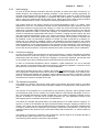
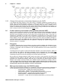
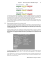
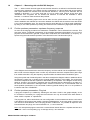
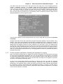
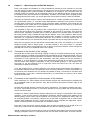
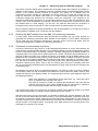
APPLICATION NOTE AN003 DOCSIS 2.0 Analyzer KWS-Electronic GmbH Tattenhausen Sportplatzstrasse 1 83109 Großkarolinenfeld Phone: 0049 .8067 .9037-0 Fax: 0049 .8067 .9037-99 E-Mail: [email protected] www.kws-electronic.de Contents 1 Contents CONTENTS 1 CHAPTER 1 2 About this document ----------------------------------------------------------------------------------- 2 Revisions ---------------------------------------------------------------------------------------------------- 2 Reference documents ------------------------------------------------------------------------------------ 2 Contact with the manufacturer ------------------------------------------------------------------------- 2 1.1 1.2 1.3 CHAPTER 2 2.1 2.2 2.3 2.4 2.5 2.5.1 2.5.2 2.5.3 2.5.4 2.5.5 2.5.6 2.6 2.7 2.8 2.9 2.10 CHAPTER 3 3.1 3.1.1 3.1.2 3.1.3 3.1.4 3.1.5 3.1.6 3.1.7 3.2 3.2.1 3.2.2 3.2.3 3.2.4 3.2.5 3.2.6 3.2.7 3.2.8 3 Basics ------------------------------------------------------------------------------------------------------- 3 DOCSIS standard ----------------------------------------------------------------------------------------- 3 EURO-DOCSIS and US-DOCSIS --------------------------------------------------------------------- 3 The downstream ------------------------------------------------------------------------------------------- 4 The upstream----------------------------------------------------------------------------------------------- 4 Ranging ------------------------------------------------------------------------------------------------------ 6 The MAC address ----------------------------------------------------------------------------------------- 6 Extracting upstream parameters from the downstream ------------------------------------------ 6 Initial ranging ----------------------------------------------------------------------------------------------- 7 Continuous ranging --------------------------------------------------------------------------------------- 7 The upstream equalizer ---------------------------------------------------------------------------------- 7 Change of the upstream or downstream frequency by the CMTS ---------------------------- 8 Further modem synchronisation and registration with the CMTS ----------------------------- 8 Encryption --------------------------------------------------------------------------------------------------- 8 Main synchronisation steps of a DOCSIS modem ------------------------------------------------ 8 The ping test ------------------------------------------------------------------------------------------------ 9 Ingress ------------------------------------------------------------------------------------------------------- 9 10 Measuring with the DOCSIS Analyzer----------------------------------------------------------- 10 Measurement process --------------------------------------------------------------------------------- 10 Connection ------------------------------------------------------------------------------------------------ 10 Measuring the downstream at the customer outlet ---------------------------------------------- 10 Measuring the upstream at the customer outlet ------------------------------------------------- 11 Further upstream parameters: advanced time slot analysis ---------------------------------- 13 Further upstream parameters: upstream frequency response ------------------------------- 14 Further upstream parameters: Ping test ----------------------------------------------------------- 14 Further upstream parameters: Selecting the upstream for ranging ------------------------- 15 Comments------------------------------------------------------------------------------------------------- 16 Measuring device’s transmission and receive power levels ---------------------------------- 16 Comments to the ping test ---------------------------------------------------------------------------- 17 Comments to the duration of the ranging ---------------------------------------------------------- 18 Comments to the registration of the analyzer at the headend -------------------------------- 18 Reading the MAC address from the AMA 310 measuring instrument ---------------------- 19 Comments on downstream duty factor ------------------------------------------------------------- 19 Comments to BPI(+) ------------------------------------------------------------------------------------ 20 Compatibility to DOCSIS 3.0 systems -------------------------------------------------------------- 20 AN003 DOCSIS-2.0-Analyzer 11V00.02 2 Chapter 1 - About this document Chapter 1 About this document This document contains information about the “DOCSIS-2.0-Analyzer” option of the AMA310 antenna measuring receivers. 1.1 Revisions V00.01 January 2011 First release V00.02 September 2011 Update 1: Upstream for ranging can be selected; this requires an update to the FPGA configuration of the DOCSIS-2.0 analyzer (can only be carried out at the factory; not required for analyzers supplied after September 2011) and a firmware version of the AMA 310 of Vxx.07a or higher Update 2: Downstream channel utilization can now also be illustrated in diagram form as a function of time; this requires: Firmware version Vxx.07a or higher Update 3: MAC address of the modem can be read from AMA 310; this requires: Firmware version Vxx.07a or higher. 1.2 Reference documents This application note refers to the following documents: AMA 310 Antenna Measuring Receiver operating manual DOCSIS 2.0 specifications (http://www.cablelabs.com/cablemodem/specifications/specifications20.html) 1.3 Contact with the manufacturer For information about KWS-Electronic products please visit our website www.kws-electronic.de. Contact details can also be found there. AN003 DOCSIS-2.0-Analyzer 11V00.02 Chapter 2 - Basics 3 Chapter 2 Basics 2.1 DOCSIS standard The analyzer of the measuring receiver either conforms to the DOCSIS 1.1 or DOCSIS 2.0 specification depending on which option has been fitted. DOCSIS stands for “Data over Cable Service Interface Specification”. The standard sets the rules for fast, bi-directional communication and IP data exchange between the headend and the user either via a pure coaxial network or an HFC network (Hybrid Fibre/Coaxial). The counterpart station for the cable modem (CM) on the user side is the CMTS (Cable Modem Termination System) in the headend. The data from the headend to the customer is transmitted in the so-called downstream (DS); information returning from the customer is transmitted in the upstream (US). The US and DS are transmitted in the same cable but in different frequency ranges. 2.2 EURO-DOCSIS and US-DOCSIS There are two different DOCSIS specifications: EURO-DOCSIS und US-DOCSIS. The former takes North American conditions into consideration while the latter is adapted to the European conditions. US-DOCSIS is often simply known as DOCSIS (as this was the standard that was first introduced) and EURO-DOCSIS in turn as EuroDOCSIS. For the sake of clarity this document uses both terms in the headers. Both standards can be measured with the measuring receiver. The differences lie in the DS forward error correction (FEC) and in the DS channel bandwidths or in the channel rasters respectively and in the DS and US frequency ranges. The message contents exchanged between headend and user are identical in both specifications. The following tables summarize the differences between the two systems. AN003 DOCSIS-2.0-Analyzer 11V00.02 4 Chapter 2 - Basics Similarities and differences in the forward path (DS): Modulation type Symbol rate FEC Channel bandwidth Transmission frequency range US-DOCSIS 64-QAM, 256-QAM 5057 und 5361 kSymb/s J.83/B 6 MHz EURO-DOCSIS 64-QAM, 256-QAM 6952 kSymb/s DVB-C 8 MHz 50…862 MHz 112…862 MHz US-DOCSIS EURO-DOCSIS 5…42 MHz 5…65 MHz Difference on the return path (US): Transmission frequency range 2.3 The downstream Data from the headend is sent continuously in the downstream to the modems in MPEG data streams. In the spectrum it is therefore not possible to differentiate between a DOCSIS downstream and a DVB-C television channel (in the case of US-DOCSIS a J.83/B channel). The only difference to DVB-C is a special symbol rate which does not occur with DVB-C. Even the forward error correction (Reed Solomon with EURO-DOCSIS; Reed-Solomon and Viterbi with US-DOCSIS) is identical to the TV channel transmission. With the support of the QAM-orders, the symbol rates and of the FEC overhead the total DS net data rate for EURO-DOCSIS of 38.44 Mbit/s (64-QAM) or 51.25 Mbit/s (256-QAM) and for US-DOCSIS of 26.97 Mbit/s (64-QAM) or 38.81 Mbit/s (256-QAM) can be calculated. After the synchronisation on a downstream and after demodulation the connected modems recognise the MPEG packets, which contain DOCSIS information, via a special packet identification number (PID; for DOCSIS 0x1FFE) in the packet header. In general, not all MPEG packets of a DS channel contain DOCSIS information. This depends on how many modems are currently requesting data from the CMTS. As we are dealing with a continuous data stream with a fixed symbol rate in the downstream this means that so-called zero packets have to be inserted if the complete bandwidth is not required. These carry the PID 0x1FFF and are not evaluated by the modems. The following figure shows a sequence of MPEG packets which might be received by a modem after the RF demodulation. Each modem in a DOCSIS network also receives the data for all the other modems connected in the network. Once again, using special identification numbers each modem filters out the valid data intended for itself; all other data must be ignored. 2.4 The upstream Conditions in the upstream are a little more complicated. Depending on the number of modems on a network segment and how the headend is equipped one or a small number of upstream frequencies will be offered to the modems. This means that multiple modems need to transmit on the same frequency. The allocation of upstream bandwidth is made using time division multiple access (TDMA). AN003 DOCSIS-2.0-Analyzer 11V00.02 Chapter 2 - Basics 5 Using this method the upstream is divided into individual time slots. The headend assigns each modem time slots, within which the modem can send its data to the CMTS. It is not possible to use time slots reserved for other modems. The following figure shows this procedure. The vertical axis represents the US frequency range (5 MHz to 65 MHz). We will assume that two upstreams at 15 MHz and 45 MHz are available and that the transmission bandwidth amounts to 3.2 MHz, which corresponds to a symbol rate of 2560 kSymb/s (see below). The horizontal axis is the timeline. The CMTS must plan the time so that each modem is served. Different time slot types are available for the communication between modems and headend. Some time slots are provided for setting up and maintaining a connection between the CMTS and the modem, others purely for data exchange. The connection setup made between the devices is called “ranging” (see next chapter). If a modem is switched on there is still no connection with the CMTS and therefore no time synchronization, which is essential for transmission in well defined timeslots. For an initial contact of the modem to the headend very long time slots (called "Initial Maintenance") are available in which all modems send in competition. In these long slots the time synchronisation is not so crucial. These allow the modems to report to the headend, synchronising with it and letting it be assigned its own time slots. As soon as a first contact is made, the connection between the modem and CMTS has to be maintained. For this transmission opportunities are periodically available in which each modem has to report to the CMTS (“Station Maintenance”). Various checks are made including to see if the time synchronisation is kept exactly. If the modem wants to send data it can request bandwidth from the CMTS in time intervals called "Request" or "Request/Data”. Depending on the volume of data to be sent the headend reserves a “Short Data Grant” or a “Long Data Grant” for the modem. These time slots are then reserved and the modem can transfer its data without being interrupted by other modems. In addition to these basic time slot types from the DOCSIS 1.0 and 1.1 specifications in DOCSIS 2.0 there are the “Advanced PHY Short Data Grant”, the “Advanced PHY Long Data Grant” and the “Advanced PHY Unsolicited Grant” as well. The CMTS must not necessarily offer all the time slots. It must only ensure that the modem can establish a connection (via Initial and Station Maintenance) and that intervals to transmit data are available. As well as the time multiplexing multiple access mode (many modems sharing one transmission frequency) DOCSIS 2.0 supports S-CDMA (synchronous code division multiple access). With this method the modems must also adhere to time slot sharing (therefore “synchronous”). However up to 128 modems can transmit simultaneously within a single time slot. This is possible as each modem is allocated a certain code which the modem multiplies with its transmission signal. By means of the mathematical correlation operation it is possible for the CMTS to allocate the messages arriving at the same time to the corresponding modems. S-CDMA is however deployed much more seldom by network operators than pure TDMA. Various modulation types and symbol rates are available in order to send in a time slot. QPSK and 16-QAM are stipulated in the DOCSIS 1.x specifications. 8QAM, 32-QAM, 64-QAM and 128-QAM are additionally available in DOCSIS 2.0. The symbol rates include 160 kSymb/s, 320 kSymb/s, 640 kSymb/s, 1280 kSymb/s, 2560 kSymb/s and as from DOCSIS 2.0 also 5120 kSymb/s. To calculate the necessary bandwidth from the symbol rate simply multiply using factor 1.25 (as the so-called Roll-Off-Factor in the upstream amounts to 0.25). This results in the following bandwidths: 200 kHz, 400 kHz, 800 kHz, 1600 kHz, 3200 kHz and for DOCSIS 2.0 6400 kHz. AN003 DOCSIS-2.0-Analyzer 11V00.02 6 Chapter 2 - Basics As mentioned previously only QPSK and 16-QAM modulation is available with DOCSIS 1.1 and that with a symbol rate up to 2560 kSymb/s. This variant is known as standard TDMA. In DOCSIS 2.0 we have A-TDMA (“advanced” TDMA) - a result of higher modulation grades, greater bandwidth and the advanced time slots. While for an upstream frequency the symbol rate for reasons of time synchronization is always constant and is equal for all modems, the QAM order in the various time slots can be different. The cable network can be operated under different modes. In the pure DOCSIS 1.1 mode the advanced time slots, the highest symbol rates and the high level modulations are not available. Most of the modems used with the network are of the DOCSIS 1.1 type. DOCSIS 2.0 modems can be operated in DOCSIS 1.1 as they are downward compatible; however their full throughput is not possible. In pure DOCSIS 2.0 mode only DOCSIS 2.0 modems are served by the headend. In this case it is not possible for the DOCSIS 1.x modems to establish contact with the headend. This modus is generally only used in a network segment where only DOCSIS 2.0 modems are deployed. If it is necessary that both modem types are able to establish a connection then a so-called “mixed mode” can be activated allowing modems of both specifications with their individual transmission conditions to be served by the CMTS. 2.5 Ranging The purpose of the so called ranging is to establish a physical connection between the headend and the modem and maintain this for the complete duration of modem operation. Above all it ensures that the time synchronization between devices always matches exactly and that the messages that each modem sends to the CMTS are sent with the correct power level. The CMTS in the headend communicates normally with numerous modems, which are all at differrent distances to the headend. The mechanism for the time synchronisation in the DOCSIS specifications allows the modems to be located up to 160 KM from the headend. This means that the transmission data for each modem must make its way through very different cable paths and a highly variable number of amplifiers. If each modem were to operate with the same power then the CMTS would have to deal with receive levels of enormous differences in short successive time slots, which is simply impossible. In addition, messages from modems located further from the headend require longer than those closer to the headend. During the ranging the transmitting power and the transmission time of the modems are corrected and adjusted that each message from each modem arrives at the CMTS with the same power and at the precise time as expected by the CMTS. 2.5.1 The MAC address The MAC address is the modem hardware address. It consists of 48 bits and uniquely identifies the modem globally, i.e. there are no two modems with the same MAC address. Normally it is written in hexadecimal format, e.g. 00-50-C2-A2-C4-65 or 00:50:C2:A2:C4:65. The modem’s MAC address is contained in the header of every message sent by the modem to the CMTS. Even during the ranging and synchronisation process of a modem (see below), when further identification numbers and addresses are assigned to it the MAC address remains the modem’s unique identifier. MAC addresses are centrally allocated by the IEEE. The composition of the MAC address is so construed that it is possible to recognise the manufacturer of a hardware component. The manufacturers can normally be identified in a central database. 2.5.2 Extracting upstream parameters from the downstream The start of connection establishment between the modem and CMTS is as follows. In general the modem synchronises on a downstream after a channel scan. In case of the measuring receiver synchronisation is done after direct channel input by the user. Then the modem tries to decode the MPEG data stream after the demodulation. The modem finds DOCSIS-specific packets in the MPEG data stream. The modem searches at the beginning for information about the available upstream(s) and the rough time synchronisation. This data, which can be understood by all cable modems, is sent from the CMTS in regular intervals down the cable network. In this way the modem can get the upstream frequency/frequencies from the downstream, the required symbol rate(s), information about the offered time slots and the modulation(s) to be used as well as basic synchronisation data about the transmission intervals on the time line. Many important parameters such as the upstream FEC, a preamble which is to be sent before each message, data regarding the scrambling of the transmission data and much more data, without which it would not be possible to synchronise with the headend, is read by the modem from the downstream. AN003 DOCSIS-2.0-Analyzer 11V00.02 Chapter 2 - Basics 2.5.3 7 Initial ranging As soon as all the relevant information about the upstream is known the modem chooses an upstream frequency and configures its sending modulator. It then waits for a sending opportunity for the initial communication with the CMTS, i.e. an “Initial Maintenance” time slot. As the modem is still unknown at the headend it is generally in competition with other modems. Therefore it is possible that by chance two modems send at the same time or slightly apart from another and the headend fails to understand either of them. Therefore the following procedure has to be used. The modem sends its first ranging request at its lowest transmission power in a random “Initial Maintenance” time slot. If it receives an answer from the headend within a given timeout it then proceeds with continuous ranging (see next chapter). If it does not receive an answer then there has either been a message collision with another modem or the transmission power was too low and the CMTS was therefore not able to receive the message. The modem then waits through a random number of transmission opportunities after which it re-sends a ranging request however this time with 3dB increased transmission power. The modem continues to select random transmission opportunities with the transmission power being continuously raised until an answer is received from the headend. If after 16 transmission attempts no answer has been received then a different upstream has to be selected to establish contact. If all upstreams that were reported to the modem from the downstream have been tested and there is still no answer then the modem must scan for a further downstream (or the measuring device user must enter a new downstream). This procedure is to be repeated until an upstream/downstream combination has been found with which the ranging can function and as a result the connection between the modem and the CMTS can be established. 2.5.4 Continuous ranging As soon as the CMTS has received the first ranging request from a modem it allocates an individual reserved interval for continuous ranging. On top of that the modem receives correction data for the transmission power and timing. The aim of the ranging is, as previously explained, that the data sent by the modem arrive at the headend with the required level and in the exact time slot. In order to compensate temperature drift for amplifiers, crystal frequencies, etc. and to intercept other changes on the transmission channel the ranging is periodically repeated in intervals of a few seconds so as to ensure the connection is correctly maintained. If the CMTS requests ranging from a modem, the modem must respond to this. In the case of periodic ranging each modem has its own time intervals as the CMTS is now aware of the modem. Normally the time interval between two rangings, used to validate the connection, is between 5 and 20 seconds. The DOCSIS speciation stipulates an upper limit of 30 seconds. The process is vital and is executed for the modem’s complete service life. 2.5.5 The upstream equalizer The equalizer is a feature, which every cable modem must support, but whose usage is, according to DOCSIS, optional. This means that the upstream equalizer is not deployed by every network operator. The purpose of the equalizer is to compensate for the frequency response, which possibly shows the transmission path from the modem to the CMTS within the transmission bandwidth of the modem. The DOCSIS specification provides a digital filter in the modem’s upstream modulator for this purpose. In DOCSIS 1.1 this filter has 8 complex parameters (i.e. each parameter consists of real and imaginary parts); in DOCSIS 2.0 there are 24 parameters. The CMTS can calculate filter parameters if the QAM spectrum of a modem offers a frequency response on arrival at the headend and report these parameters during the ranging procedure to the modem. The modem has to enter the parameters into its equaliser. Thus it sends its messages with a frequency response that is antipodal to the channel’s transmission characteristic. In this way the message arrives at the upstream input of the CMTS ideally without distortion, i.e. without frequency response. The reason for a frequency response in the transmission channel might be for example damage to the cable allowing the occurrence of micro-reflections. The following picture shows the structure of the equalizer. AN003 DOCSIS-2.0-Analyzer 11V00.02 8 Chapter 2 - Basics 2.5.6 Change of the upstream or downstream frequency by the CMTS It is possible that during ranging or even later during a completely established connection the upstream and/or downstream frequency changes. A reason might be that in a DOCSIS network with several upstream and downstream frequencies an operator might be using a software tool to balance the usage of the frequencies so that sufficient bandwidth is available for all the modems. If a modem is informed during ranging that the upstream that it is using to transmit or the downstream that it is using to receive is to be changed then it must comply. 2.6 Further modem synchronisation and registration with the CMTS After the physical connection between the modem and CMTS has been established through the ranging an IP connection is set up. For this the modem receives its own IP address via DHCP (Dynamic Host Configuration Protocol). The modem is then provided with the TOD – time of day. To complete the registration the modem has to download a configuration file (config.-file) from the network operator’s server with help of TFTP (Trivial File Transfer Protocol). The modem receives further details in this file with regards network access at IP level, about a possible message encryption between modem and CMTS and many other mandatory and optional parameters. If this file has been successfully downloaded then the registration, excepting any optional encryption (see following chapter), is completed. 2.7 Encryption In DOCSIS networks there are two different encryption systems available. BPI (Baseline Privacy Interface; introduced with the DOCSIS 1.0 standard) and BPI+ (since DOCSIS 1.1). The encryption is based on certificates, which are different for US- and EURO-DOCSIS, and must be acquired from two central points. The deployment of encryption is optional and therefore depends on the network operator. If BPI(+) is to be used then the modem is informed at registration via the configuration file. The modem must then set up the encryption for the message exchange with the headend. Only the messages for maintaining the physical connection (ranging) must be transmitted unencoded. BPI encodes the messages between cable modem and CMTS in both directions and protects the message from being read by a 3rd-party. BPI+ goes one step further offering the network operator protection from unauthorised modems. With this type of encryption the serial number and MAC address of the modem must be included in the certificate which is necessary for setting up the encryption. This prevents the cloning of modems, porting of MAC addresses and re-usage of certificates. With BPI+ if the serial number and the MAC address of the modem do not match the certificate then the use of the operator‘s service is not possible. 2.8 Main synchronisation steps of a DOCSIS modem Taking the aforementioned procedures into consideration during the ranging and the registration it can be distinguished between the following essential synchronisation steps for a DOCSIS modem: Unsynchronized → Modem has no DS synchronisation Synchronized → Modem has synchronised itself on a DS UsParameters Acquired → US parameters were extracted from the DS Ranging Complete → Ranging with the CMTS was successful DHCP Complete → Modem was allocated an IP address Operational → Config.-file was successfully loaded, BPI(+) is active (if used) AN003 DOCSIS-2.0-Analyzer 11V00.02 Chapter 2 - Basics 2.9 9 The ping test The ping test is a diagnostic tool, well known from the PC world, with which it is possible to assess the quality of an IP connection. Here certain IP packets are sent to a host to which it must respond (providing the protocol is supported). It is possible to determine the quality from the number of answers arriving for sent ping packets and from the answering time (round trip delay). A modem can only execute this test if an IP address has been allocated by DHCP (see above) as an IP connection is required for a ping test. 2.10 Ingress Ingress is electromagnetic distortion which can be injected into coaxial cable plants. Possible sources include strong short wave transmitters, CB radio, household devices, baby phones, switching-mode power supplies and much more. Ingress into the cable network is often a result of defective connectors, kinks in the cable, damage to the cable shielding, deployment of cable with inadequate shielding, etc. Ingress reduces the SNR of the upstream signal and can therefore lead to errors in the transmission. The result is that the required data rate in the cable network can no longer be guaranteed. It is therefore of highest priority to keep the ingress as low as possible. Network operators can also minimise distortion by carrying out exact analysis of the ingress in the various network segments and by putting the upstream frequencies in areas with low interferences. Please refer to the user guide for information on measuring ingress with the AMA 310. AN003 DOCSIS-2.0-Analyzer 11V00.02 10 Chapter 3 - Measuring with the DOCSIS Analyzer Chapter 3 Measuring with the DOCSIS Analyzer 3.1 Measurement process 3.1.1 Connection To measure the DOCSIS parameters the measuring device must be connected via an IEC-connector to F-connector adaptor using the F-connector of a multimedia outlet with incoming DOCSIS signal. A further usage is for example the direct connection to a house distribution amplifier with return path in an interactive cable network. From here on we will assume that the verification and the evaluation of the DOCSIS functionality at the customer site will be carried out at the customer outlet. 3.1.2 Measuring the downstream at the customer outlet In the user guide you can read how a DOCSIS downstream is found with the measuring device per channel scan or how a known DS channel can be entered directly. The measuring receiver recognises automatically if it is dealing with a EURO or US-DOCSIS signal. If you want to verify that a DOCSIS connection is functioning correctly at the customer outlet then the DS level is the most important parameter to ensure that the modem is working without any issues. The DOCSIS specification states an input level range from 45 dBµV to 75 dBµV for the modem. Two things should be observed. Firstly, the level at the customer outlet should not be adjusted to either of the two limits so as to maintain reserves, both up and down. It should be possible for example to deal with amplification variations or temperature dependencies of all components between the headend and the customer outlet so as to be able to detect good receiver characteristics. Secondly, the DOCSIS downstreams are usually embedded in the spectrum between digital and analogue TV channels. Also the power level of those channels has to follow certain rules, for example that a 64-QAM channel is lowered by about 10 dB, a 256-QAM by about 4 dB compared to a PAL transmitter. That means that a 256-QAM DOCSIS downstream, which lies in the spectrum beside a 256-QAM TV channel, should not differ too much level wise. As a first indication, the DS levels at the customer outlet between 55 dBµV and 68 dBµV are probably realistic; however they are of course dependent on many factors. The DOCSIS specification does not state any limit values for the important MER and BER parameters, however the limits can be calculated from theory. Mathematical calculations show that for a quasi error free signal (QEF) in EURO-DOCIS and DVB-C a MER value of at least 23 dB with 64QAM and of at least 29 dB with 256-QAM are necessary. Error correction is possible as from these values whereby noise distorted signals for example can be so reconstructed that they can be considered error free. These values are however at the absolute limit and allow for no reserve. The slightest degradation in signal quality will result quickly in a complete loss of the data stream. You should really always measure MER values of at least 35 dB and more at the customer outlet. The US-DOCSIS is, as a result of the double forward error correction of the J.83/B standard, somewhat more robust than EURO-DOCSIS. Similar considerations can be put forward for the bit error rate. The next figure shows the values to be achieved for both parameters. Of course the downstream RF characteristics can be more accurately examined, e.g. in the constellation diagram and through analysis of phase jitter and hum modulation or through determination of the packet error rate. However, we will not go any deeper into these analysis functions in this document but instead refer you to the user guide. AN003 DOCSIS-2.0-Analyzer 11V00.02 Chapter 3 - Measuring with the DOCSIS Analyzer 11 The measuring device offers the possibility to execute the DOCSIS analysis for the downstream only. That means that in the activated DOCIS mode the upstream transmitter is deactivated (see user guide) during the measurement of the aforementioned parameters either after the direct input of the channel or after a channel scan or during every type of automatic measurement. If the upstream transmitter is activated the analysis of the upstream and the ranging begins providing the previously described parameters are of sufficient quality and the demodulator can log itself onto the DOCSIS signal. 3.1.3 Measuring the upstream at the customer outlet If the upstream transmitter is activated the analyzer must be booted on entering the DOCSIS analysis mode. The boot procedure has only to be carried out once. As long as you remain in the DOCSIS analysis mode the analyzer remains in booted status. This means that a new analysis is immediately possible after changing to the constellation diagram view and back again or after entering a new downstream signal. After the booting procedure has completed the DOCSIS analyzer begins to extract the upstream transmission parameters from the downstream as described above. Then the analyzer tries to contact the CMTS on all available upstream frequencies. The measuring device’s monitor shows the following data if the ranging has completed successfully. See Chapter 2 for an explanation of the readings. The upper line provides information about the DOCIS system which is currently being measured. Here it is possible to read whether a pure 1.1 or 2.0 system is being deployed, or if the network is operating in mixed-mode. In the following line you can see if also the DOCSIS analyzer has recognised the downstream as being valid, i.e. if it can log in completely. The reason for this is that two DS demodulators work in parallel in the measuring receiver. AN003 DOCSIS-2.0-Analyzer 11V00.02 12 Chapter 3 - Measuring with the DOCSIS Analyzer One downstream demodulator is responsible for the very accurate measurement of the RF parameters (MER, BER, constellation, hum, phase jitter, packet errors). A second demodulator works independently in the analyzer and its sole responsibility is for the communication with the CMTS. The DS duty factor provides information on how many MPEG packets of the DS data stream, carry the DOCSIS PID (pack identification) 0x1FFE in relation to all the incoming packets. In the next line the display changes after “Upstream:” from “Searching...” to “valid” as soon as an upstream has been found for the selected downstream on which ranging is possible. The next two lines display information about the upstream frequency in which the ranging is currently taking place and about the symbol rate that the CMTS is providing for the upstream. As many DOCSIS modems must communicate with the CMTS on the same upstream frequency the modems must therefore share the upstream channel (see Chapter 2.4). The access method to achieve this can be read in the next line in the monitor. In the line below you can see the modulation of the station maintenance time interval, i.e. the modulation with which the ranging is currently executed. The status of the ranging process can be found below that after “Ranging:”. The status reads “running…” if an upstream has been found, declared valid and the ranging has started. If the CMTS reports that the ranging has completed successfully then the status changes to “finished”. The information which can be read here is related exclusively to the creation of the connection on the physical layer and does not give any indication of the further registration steps, i.e. DHCP, configuration file and BPI(+). It only concludes that the connection between the CMTS and a modem at the measurement position is basically functioning. During the ranging the modem receives correction values with regards the transmission power from the CMTS. These correction values can be seen under “Level-Offset:” in the monitor. The modem continuously adjusts its transmission power so that its level offset becomes zero. That means that messages that are sent by the modem arrive at the CMTS at the required level. If the offset is not equal to zero, for example at the time a return path amplifier is adjusted and thus the amplification changes during the measurement, the modem adjusts its transmission power so that at the next exchanging of ranging messages the offset is once again equal to zero. If the level offset is constantly not equal to zero then there is an error in the return path. Example: the modem sends at 114 dBµV and the level offset shows +9 dB then the modem would have to transmit at 123 dBµV so that the transmission power is correctly accepted at the headend; the modem is not able to manage this level; a possible cause of error is an incorrectly adjusted or faulty return path amplifier. The parameter “Stack-State” provides information about how far the analyzer can synchronise or log on to the CMTS (see also Chapter 2.5 to 2.8). Depending on the cable operator it is possible that the upstream or downstream frequency changes during the measurement. This is because the CMTS, in order to obtain a balanced utilization of all channels, can force the modem to move to other frequencies in systems with multiple upstream and downstream frequencies. The measured value display always shows the frequency the modem is using to receive data. The same applies to the graphic monitor which always shows the frequency which is being used to transmit. In theory it is also possible for further upstream parameters to change during measurement. One of the most important uses of the DOCSIS analyzer is to aid the adjustment of the return path amplifier(s) in an in-house distribution network so that all the modems in the building function with optimal transmission power. As a rule of thumb the transmission power shown in the measuring device should lie between 98 dBµV and maximal 110 dBµV. This level corresponds to the transmission power that a modem at the position of the measuring receiver would need to send its messages to the CMTS with the required level. Please note that the transmission level at the customer outlet furthest from the return path amplifier should still be within the acceptable range. AN003 DOCSIS-2.0-Analyzer 11V00.02 Chapter 3 - Measuring with the DOCSIS Analyzer 13 This means that in a long cascade where a customer outlet, located a long distance from the return path amplifier, is set to 105 dBµV a modem which is very close to the amplifier needs much less transmission power. Furthermore, it should be noted that there are some network operators or their subcontractors who have their own thresholds in which the modem transmission level should lie. The aforementioned values are a rough guide as according to the DOCSIS specification cable modems must demonstrate a dynamic range from 68 dBµV to 118 dBµV. In practice extremely high and low transmission levels are to be avoided at all costs. As the modem level is normally adjusted at the customer outlet and the return path amplifier is in the cellar or lower floor of a building either a second person or plenty of leg work is required to set the amplification. The following workflow might perhaps be useful. - - - 3.1.4 The upstream transmission power is measured at the “worst” customer outlet and this value is noted. (Example: 114 dBµV; condition: a DOCSIS analysis is already possible here.) The same analysis is carried out directly at the house amplifier. The difference between the transmission power at the customer outlet and at the house amplifier (e.g. 89 dBµV) is the attenuation of the return path signal in the house – in this case 25 dB. The return path amplifier is adjusted so that the sending level receives the value of the “required transmission power at the customer outlet” (e.g. 105 dBµV) minus “attenuation from the customer outlet to the return path amplifier”, i.e. approx. 80 dBµV. Check the customer outlet again to see that the required transmission level has been adjusted. Further upstream parameters: advanced time slot analysis By selecting the menu item “ADVANCED” in the monitor, information is provided about which time slots are being offered in the DOCSIS network and which modulation the CMTS specifies for the various time slot types. The following terms (see Chapter 2.4) as used in following: Request Request / Data Initial Maintenance Station Maintenance Short Data Grand Long Data Grant Advanced PHY Short Data Grant Advanced PHY Long Data Grant Advanced PHY Unsolicited Grant the DOCSIS specification are abbreviated as → Req → Req/Data → InitMaint → StatMaint → ShortData → LongData → AdvShort → AdvLong → AdvUSG AN003 DOCSIS-2.0-Analyzer 11V00.02 14 Chapter 3 - Measuring with the DOCSIS Analyzer The “----“ behind certain time slot types shows that this interval is not offered in the DOCSIS network currently being measured. In the above time slot configuration it is also evident that we are dealing with a pure DOCSIS 2.0 network since the intervals “AdvShort”, “AdvLong” and “AdvUGS” are not available in DOCSIS 1.1. It is also clear that it is not a mixed mode network as the time slots “ShortData” and “LongData” are not offered and therefore no intervals are available in which DOCSIS 1.1 modems could send their data packets. There is another interesting aspect that can be seen from the picture above. The time slot types used to establish and maintain the connection between the CMTS and the modem have with QPSK a very robust modulation type. The time slots used to send data are of a higher grade modulation. By doing so, the cable operator is providing his customers with a satisfactory high uplink data speed. 3.1.5 Further upstream parameters: upstream frequency response As soon as the ranging procedure has finished the “FRQRESP” can be selected in the monitor. This sub-menu shows a graphical presentation of the equalizer parameters described in 2.5.5. For this purpose the discreet and in general complex filter coefficients are recalculated in a frequency response using the mathematical operation of the discrete Fourier Transformation (DFT). In the diagram the horizontal axis shows the frequency and the vertical one the amplification. Important to note is that the diagram does not offer any information about the complete return path range from 5 MHz to 65 MHz. Only the frequency response within the transmission bandwidth is given. Using the symbol rate of 2560 kSymb/s in the above example the diagram makes a statement about the frequency range from ±1.6 MHz for the channel middle frequency of 54.8 MHz. The vertical axis shows the frequencies that are amplified or attenuated by the equalizer. If the diagram shows strong peaks or troughs in the frequency response then this indicates that the cable path is not ideal, e.g. as result of micro-reflections in damaged cable, oxidised connectors, etc. If the headend does not send equaliser parameters to the connected modems (optional feature) then it is not possible to invoke the sub-menu “FRQRESP”. 3.1.6 Further upstream parameters: Ping test A ping (see chapter 2.9) is initiated by selecting the sub-menu “PING” in the graphic display. As an IP connection is necessary for a ping test the sub-menu can only be invoked if the stack status is either “DHCP complete” or “Operational”. The ping test can, within certain limits, be user-configurable. In the measurement device a sub-menu is provided for this purpose (see chapter “Instrument Management” in the user guide). Here the user can choose to send between 5 and 100 ping packets. Furthermore, it is possible to adjust the time interval between two pings; this can lie between 0.5, 1, 2 and 5 seconds. Note: If for example 50 pings are sent with a 5-second time interval then the complete test lasts 50 x 5 seconds + 50 x round trip delay (e.g. on average 20 ms) = 251 seconds. AN003 DOCSIS-2.0-Analyzer 11V00.02 Chapter 3 - Measuring with the DOCSIS Analyzer 15 The status of the test can be read in the upper line of the ping menu in the measuring device’s monitor – “initialised”, “running…” or “finished”. Under that you can see the IP address that the modem has been allocated by DHCP and the IP address of the default gateway that is being pinged. If the ping status changes to “finished” then the results are summarised in statistical format below this – sent packets, received packets, packets lost and minimal, maximal and average response time. As many pings can be sent (max. 100 packets) it does not make any sense to make a more detailed breakdown for every single ping here. The menu item “BACK” to exit the ping sub-menu can only be used after the ping test has finished completely. During the execution time of the PING test a progress information appears in the line behind „PingStatistic:“ This is done via several star symbols which are added to this line. If a maximum number of 15 star symbols has been printed the line is erased and again filled from the beginning. A star is added when the analyzer receives a correct response for a sent ping or when no response has arrived within 5 seconds after the ping has been sent. 5 seconds is the typical timeout for ping tests after which a packet is declared as lost. In this way the user has visual control over whether a test is still running even with long ping tests. The upcoming star symbols are not to be understood as indication of a successfully received answer to a sent ping packet but rather an indication that there is progress being made. 3.1.7 Further upstream parameters: Selecting the upstream for ranging Note: This function requires both an update to the FPGA configuration of the DOCSIS-2.0 analyzer for instruments supplied before September 2011 (can only be carried out at the factory; not required for instruments supplied after September 2011) and a firmware version of the AMA 310 of Vxx.07a or higher. If these two conditions are not met, the menu item "US-FRQ." will not appear on the startup screen of the DOCSIS measuring option. As soon as the stack status "Ranging Complete" is reached, the user can select an upstream frequency for the measurement (if several upstream frequencies are offered for the selected downstream). As described above, during the ranging process the modem searches automatically for a frequency at which communication with the headend functions. If, however, you also want to determine the transmission level or frequency response at other upstream frequencies, it is possible to do so via the submenu "US-FRQ.". AN003 DOCSIS-2.0-Analyzer 11V00.02 16 Chapter 3 - Measuring with the DOCSIS Analyzer This submenu contains a list of all the upstream frequencies with an associated upstream ID offered by the CMTS. The number of upstreams displayed is limited to 20. A star symbol marks the upstream on which the modem is currently in contact with the CMTS. Using the arrow keys on the measuring receiver, an upstream can be selected on which the modem is to make a ranging request. (If more than four upstreams are offered, these are listed by the measuring instrument on several pages of the submenu, which can be scrolled using the <- and -> arrow keys.) The change to a new frequency is made by pressing ENTER. The modem then attempts to establish contact with the CMTS at the new upstream frequency AFTER completion of the next ranging process with the headend. This means that changing to the new upstream can take a few seconds. The change takes effect after the next beep, which signals that ranging has successfully completed. The menu for selecting the upstream frequency closes. After successful synchronisation on the new upstream, the parameters are displayed in the same way as after an initial automatic search for a valid upstream channel. Selecting the upstream marked by a star symbol (i.e. on which the modem is transmitting at that moment) causes nothing to happen. Only the “US-FRQ.” submenu closes. It may happen that ranging does not work on a selected upstream. On the one hand the load on the new upstream may be so great that the headend simply cannot serve the modem. On the other it may be that the CMTS currently contacted by the modem does not support a choice of upstream via the modem. While in principle this should always be possible according to DOCSIS specification, there are CMTS producers who do not implement this function. Another reason for not being able to lock in on a desired upstream may be that, although cable network operators send information via the downstream about all their upstream channels, in the network segment currently being measured not all upstreams are served by the headend, or some upstreams are not even physically connected to the CMTS. In such instances the modem behaves exactly as it does after being switched on. If it is not used on an upstream selected by the user, it scans all upstreams via which parameters are transmitted to the modem in the downstream until it receives a response from the headend. It is therefore theoretically possible that after the instrument has been switched on and used to measure an upstream "a", then an upstream "b", that it displays the parameters of an upstream "c" for further measurements. An equally possible scenario in theory is that synchronisation can be performed on the selected upstream and all parameters are displayed correctly. However, the utilization on the upstream may be so great that the headend sends the modem straight back to its previous upstream for reasons of equal distribution of utilization. The modem MUST comply with this mechanism. 3.2 Comments 3.2.1 Measuring device’s transmission and receive power levels AN003 DOCSIS-2.0-Analyzer 11V00.02 Chapter 3 - Measuring with the DOCSIS Analyzer 17 In the technical specifications the measuring device’s receiving level for the DOCSIS analysis option is given as 50 dBµV (see user manual), although the DOCSIS specification stipulates 45 dBµV as the lower limit for modems. The reason for this is that in the measuring receiver two demodulators work in parallel. One, as mentioned above, is purely for DOCSIS analysis while the other is for the high grade measurement of the RF parameters. One of the highlights of the AMA 310 is its ability to show a real time constellation in parallel to the running DOCSIS analysis. This is only possible if the downstream signal is divided device-internally so as to simultaneously arrive at different boards. The measurement of MER, BER, constellation, etc. is possible for the complete level range from 20 dBµV to 120 dBµV such as in the DVB-C case. For the evaluation of the downstream by the DOCSIS analyzer as a result of the complex frequency responses within the measuring device a value of 50 dBµV was specified with plenty of reserve. In most cases however, a DOCSIS analysis is possible without any problem for levels above 45 – 47 dBµV. Please note furthermore, that at the customer outlet the downstream level should in any case be above 55 dBµV. Levels are much higher anyway for measurements directly taken at the house amplifier. For measurements taken directly at the amplifier or even at the headend there is the advantage that for high DS levels the complete measurement range up to 120 dBµV is available and users of the AMA 310 are not limited to the standard upper DOCSIS limit of 75 dBµV. The following can be said about the maximal upstream transmission level. Also this parameter is cautiously given as 114 dBµV in the technical data. This is fully sufficient to measure every customer outlet as a modem’s transmission power should normally be around 100 dBµV or even slightly higher. Once again as a result of complicated device internal frequency responses and attenuation settings it is normally possible to achieve much higher levels up to 120 dBµV. It depends on the absolute frequency of the upstream as well as on the level of the downstream. One has to be aware that these high levels, which extend beyond the DOCSIS specifications, produce distortions which could disturb other modems or - depending on the ratio of DS to US frequency - make it difficult to receive downstreams or at least influence the MER and BER. These high transmission powers can nevertheless be useful for measurement and diagnosis purposes, if for example a customer modem cannot establish connection with the CMTS. If the measuring device can manage to execute ranging with a transmission power of 120 dBµV then the cause might be that the return path is basically fully ok but the return path amplifier is incorrectly set. As a result of the possible influences on other devices after detecting the problem the measuring receiver should not be left in the network. A further diagnosis tool is the level offset. This can be used to help identify if the amplification in the return path is insufficient or the cable attenuation is, as a result of damage, too high even though the return path amplifier is correctly set. With a normal DOCSIS modem it is not possible to see why the connection has not been possible – you only see that the upstream LED is off or blinks and that you cannot get an Internet connection. With the DOCSIS analyzer’s level offset it is possible to get the following scenario: the modem sends at 114 dBµV and the level offset shows +9 dB. The modem would then have to transmit with 123 dBµV so that the transmission power is accepted by the headend and the status “Ranging Complete” is reached. However, no modem can send with this transmission power. The ranging will never complete. However, because the CMTS can basically understand the DOCSIS analyzer even with a transmission power that is too low and gives feedback about this situation, it is possible to narrow down the potential source of the problem. 3.2.2 Comments to the ping test When evaluating the ping test the experience with the network and the behaviour of the headend technology in the network that is being measured play a major role. A blanket statement about which ping statistics can be defined as “good”, which as “satisfactory” and which are “poor” or ”bad” is generally very difficult. Not every CMTS answers the pings at the same speed. This means that the minimal, maximal and average response time can vary from vendor to vendor. On top of that it also depends on how much data traffic the CMTS is currently managing, i.e. how many connected modems are online and how many uploads and downloads are being requested by the users. Furthermore, the first ping often generally gets lost if the headend has not had to answer a ping for a considerable period of time. It is always advisable for ping statistics regarding packet losses to repeat the test at least once if not more often to determine if the loss is a once-off or a systematic problem. In very seldom cases it can happen that a network operator completely prevents a modem from pinging the CMTS! In such a case the ping test does not work with the DOCSIS analyzer as by default this pings the CMTS (default gateway). There are two reasons for this. AN003 DOCSIS-2.0-Analyzer 11V00.02 18 Chapter 3 - Measuring with the DOCSIS Analyzer Firstly, with regards the installation of a house distribution network the main interest is in the path from the customer outlet to the headend. From the point of view of the level ratios this path must be correctly designed and it must be possible to establish an IP connection. This connection from the customer outlet to the CMTS can be measured entirely by the DOCSIS analyzer. Everything after the headend is the network operator’s responsibility. Therefore, there is little point in pinging a public homepage because if this fails, you cannot determine if the problem is before or after the headend. Secondly, the DOCSIS analyzer used for the measurement is normally classified at the headend as an unprovisioned modem, i.e. a modem whose MAC address is unknown to the operator. The latter normally does not allow such modems to ping beyond the CMTS. Otherwise, there would also be the possibility that a modem that is not registered uses the Internet for free, which is of course and understandably prevented by the network operator. It is advisable to begin the ping analysis with a small amount of ping packets. As previously explained the timeout after which a packet is classified as lost amounts to 5 seconds. If the ping test does not work, regardless of whether this is a result of a defect or the operator does not allow it, for each sent packet it must be waited through this time window. As it is not possible to abort the test this means that a test of 80 packets can last 400 seconds. Therefore, it is better to make the initial tests with 5 or 10 packets to test the basic behaviour of the network. If this test works ok then for more accurate tests you can increase the number of packets and vary the ping interval as well. More than 100 pings at one go and shorter intervals than 500 ms are not possible as it is not the headend‘s primary task to answer pings. A number between 5 and 100 packets in 4 possible intervals between 500ms and 5000ms provide a decent compromise between sufficient diagnosis potential and not too much additional traffic in the network. 3.2.3 Comments to the duration of the ranging We would like to stress again that though ranging normally is completed relatively quickly, because of network topology complete synchronisation with the headend can be delayed somewhat. This can arise for example when several upstreams are offered in a downstream. A DOCSIS modem collects information for every upstream from the downstream. After that, ranging for the first upstream is attempted. If 16 send attempts in random initial maintenance intervals do not result in a reaction from the CMTS then ranging is attempted on the next available upstream. If the ranging is first successful on the last upstream then it might take some time before the user can read the measurement results in the monitor. It can also happen that in a network segment, even though several downstreams are available, in this particular network section, the upstreams which are being offered by a certain downstream are not served by the headend at all. It is therefore impossible to setup a connection to the CMTS with this downstream. In this case, a different DS frequency is to be entered or a search is to be made using the channel scan. 3.2.4 Comments to the registration of the analyzer at the headend When measuring in a cable network with the DOCSIS analyzer the measuring device behaves like an unregistered modem in the operator’s view. Not all operators deal with the modem rights in the same manner. Normally the DOCSIS analyzer reaches the status “Operational”. The operator classifies the analyzer as an “unprovisioned” modem. It is therefore possible to ping the CMTS and all measurements can be executed as well. It happens in seldom cases that the analyzer status does not change to “Operational” after “DHCP complete”. In this case the modem is allocated an IP address. After the DHCP the IP address of the default gateway is also known and the headend can be pinged. The “Operational” status might not be achieved because some network operators do not send the configuration file to modems with unknown MAC addresses and as a result the analyzer cannot complete the registration. Nevertheless, all measurements are possible with the DOCSIS analyzer. Even rarer is the case that a network operator does not allow its headend to be pinged at all or at least not by modems with unknown MAC addresses (see also the following chapter). Should it happen that the analyzer does not get an IP address and therefore gets stuck on the status “Ranging Complete” there is a phenomenon that the connection breaks down at certain intervals. AN003 DOCSIS-2.0-Analyzer 11V00.02 Chapter 3 - Measuring with the DOCSIS Analyzer 19 The reason is that the CMTS and the modem after successful ranging are waiting for a complete registration of the modem. The registration must be completed before a DOCISIS-specified timeout expires. If the network operator prevents the analyzer from getting an IP address then the components involved consider the registration as having failed. As a result the analyzer will no longer be served by the CMTS. This means it no longer receives reserved time slots for the continuous ranging and therefore the connection cannot be maintained. If the analyzer is not allocated a transmission opportunity for 30 seconds it behaves as if it were just switched on. That means it looks in the downstream for upstream information and restarts the connection set up with the headend with an “initial ranging”. For the user, this hast the effect that the connection is interrupted every couple of minutes for a few seconds before the measurement can continue. All the mentioned aspects are heavily dependent on the network operator. In the majority of cases it will be possible to establish an IP connection with the headend. 3.2.5 Reading the MAC address from the AMA 310 measuring instrument In some cases, lower measurements with the DOCSIS-2.0 analyzer are only made possible by specifying the measuring instrument's MAC address in the headend. For this reason the address can be read from the measuring instrument for firmware version Vxx.07a and higher (see the "Instrument Management" chapter in the operating instructions). 3.2.6 Comments on downstream duty factor It must be noted that the duty factor for a valid DOSCSIS downstream is not the ratio between the actual and the maximal possible data rate. Only the MPEG packets carrying DOCSIS data in relation to all the received packets is considered. However, generally speaking not all MPEG packets are completely filled. This means that an MPEG packet can contain a DOCSIS packet addressed to a particular modem and which only contains the volume, for example, of half an MPEG packet. If the headend at that moment does not have any further packet to send for a different modem or because there are only a few modems registered in the first place and there is therefore no necessity to send, then the rest of the MPEG packet is filled with dummy bytes which will be ignored by the modem. Therefore it follows that a shown value of 48% for the duty factor does not necessarily mean that 48% of the maximal possible data rate of the downstream is being used. Normally the real data rate is somewhat lower. Nevertheless, the shown value is a meaningful parameter. The larger the value is the more modems are requesting data over the downstream and therefore the more careful the CMTS must be with regards the capacity of the MPEG packets. The measured value can be a good diagnostic agent for the following questions: - What is the utilization of a downstream during peak times, e.g. 18:00 after office hours, compared to the morning or the night? Why does a customer’s modem not achieve the downstream data rate that the customer has paid for? One reason could be that the downstream is utilized to such an extent that the data rate left for each customer is too low. The measurement value can be helpful to the network operator when deciding whether to proceed with network segmentation or adding a further downstream into the network. With firmware version Vxx.07a and higher, it is possible to display the channel utilization over time as well as the level, MER, BER and packet errors by using the DataGrabber in DOCSIS mode (see the operating instructions chapter "Measurement Data Recording (DataGrabber)"). 500 values are recorded. The period over which the 500 values are measured can be set from 1 minute to 23 hours and 59 minutes. In the diagram below, for example, level, MER, packet errors and duty factor were measured over a period of 10 minutes. AN003 DOCSIS-2.0-Analyzer 11V00.02 20 Chapter 3 - Measuring with the DOCSIS Analyzer 3.2.7 Comments to BPI(+) As a result of the circumstances of the matching requirements with regards the MAC address and the BPI certificates as described in 2.7 it is not possible to edit the MAC address in the DOCISIS analyzer of the AMA 310 measuring receiver. 3.2.8 Compatibility to DOCSIS 3.0 systems The DOCSIS 2.0 analyzer functions in most 3.0 networks. The reason for this is that the modulations schemes in the downstream and upstream are identical to DOCSIS 2.0. The increased data rate in DOCSIS 3.0 is not achieved through additional modulation types or through higher symbol rates. Instead the higher data speeds are a result of “channel bonding”. DOCSIS 3.0 modems can receive data from several downstreams and can send on several upstreams simultaneously. As result DOCISIS 3.0 networks are always offering several downstreams. A differentiation is made between “primary” and “secondary” downstreams. In both DOCSIS 2.0 and DOCSIS 3.0 the connection setup, registration at the headend and periodical ranging are exclusively done via the primary downstreams. That means that also in pure DOCSIS 3.0 networks there must at least be one primary downstream. The 2.0 analyzer can use this to establish contact with the headend. The secondary downstreams are exclusively for use by modems capable for bonding so as to increase the data rate. Thus it can also happen that in a 3.0 network a DOCSIS downstream is found e.g. after a channel scan by the measuring device but the ranging does not work. In this case we are dealing with a secondary downstream and the search for a primary downstream has to be continued. Many major operators declare all downstreams in their network as primary, even those that 3.0 modems use for channel bundling. This means that both upstream information and ranging offers are sent on all downstreams. An exception, for which the DOCSIS analyzer does not function in a 3.0 network, is if the headend requests a 3.0 specific S-CDMA upstream format. Information about this exotic format is sent in messages to the connected modems, which a 2.0 modem cannot interpret. Hence these messages are ignored by 2.0 modems. In this case the 2.0 analyzer cannot find an upstream via the primary downstream on which ranging is possible. But this upstream format is used only very rarely up to now. There is a further additional feature in the DOCSIS 3.0 standard that can also prevent ranging with a 2.0 analyzer. In DOCSIS 3.0 the encryption mechanisms were further extended. In addition to BPI(+), which is only initialised after the IP connection set up and after loading the configuration file, there is a 3.0 encryption which can be established before the DHCP. This method is however hardly ever used. AN003 DOCSIS-2.0-Analyzer 11V00.02 Chapter 3 - Measuring with the DOCSIS Analyzer 21 A last innovation can block the 2.0 analyzer from functioning and that is the extension of the upstream frequencies in US-DOCSIS through moving the upper limit from 42 MHz to 85 MHz. This is however not valid for EURO-DOCSIS and is also rarely used. As a result it can be said that the DOCSIS 2.0 analyzer will work in most 3.0 networks. Of course it cannot use the channel bonding mechanisms. AN003 DOCSIS-2.0-Analyzer 11V00.02


![sf-list [s]](http://vs1.manualzilla.com/store/data/005727021_1-5e70d84b679a2d9887789b982f459474-150x150.png)