1
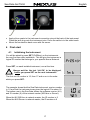
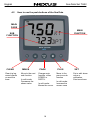
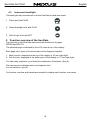
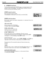
NX Sea Data Set 1
Installation and Operation Manual
English
Sea Data Set TH52
English
1
English
Sea Data Set TH52
Edition: April 2007
2
Sea Data Set TH52
1
2
3
4
5
6
7
8
English
Part specification .............................................................................................................. 5
Installation ......................................................................................................................... 7
2.1
Installing the instrument ................................................................................................... 8
2.2
Installing the WSI-box ...................................................................................................... 9
2.3
Installing the Log and depth transducers ....................................................................... 10
2.3.1
Correct location of transducer ............................................................................. 10
2.3.2
Installing the through hull fittings ......................................................................... 12
Installation ....................................................................................................................... 12
3.1
Bedding .......................................................................................................................... 12
3.2
Installing ......................................................................................................................... 12
3.3
Checking for Leaks......................................................................................................... 14
3.4
Installation in a Cored Fiberglass Hull............................................................................ 14
3.5
Electrical Installation....................................................................................................... 16
First start.......................................................................................................................... 17
4.1
Initialising the instrument................................................................................................ 17
4.2
How to use the push-buttons of the Sea Data................................................................ 18
4.3
Instrument backlight ....................................................................................................... 19
Function overview of the Sea Data................................................................................ 19
SPEED functions............................................................................................................. 20
SPEED main-function................................................................................................................. 20
SPEED sub-functions ................................................................................................................. 20
TRIP LOG (TRP) .................................................................................................................... 20
TOTAL LOG (LOG)................................................................................................................. 20
START TIMER (STA) ............................................................................................................. 20
TIMER .................................................................................................................................... 20
AVERAGE SPEED (AVS) ...................................................................................................... 20
MAXIMUM SPEED (MAX)...................................................................................................... 21
DEPTH (unit/DPT) .................................................................................................................. 21
BATTERY (BAT)..................................................................................................................... 21
TEMPERATURE (TMP) ......................................................................................................... 21
DEPTH functions ............................................................................................................. 22
DEPTH main-function................................................................................................................. 22
DEPTH sub-functions ................................................................................................................. 22
LIGHT CONTROL................................................................................................................... 22
SHALLOW ALARM (SHA)...................................................................................................... 22
DEPTH ALARM (DEA) ........................................................................................................... 22
ANCHOR ALARM................................................................................................................... 22
BOAT SPEED (BSP/unit) ....................................................................................................... 22
Barometric pressure (unit/hPA) .............................................................................................. 22
7.1.1
TRUE WIND ANGLE (TWA)................................................................................ 22
7.1.2
APPARENT WIND ANGLE (TWA) ...................................................................... 23
7.1.3
TRUE WIND SPEED TWS .................................................................................. 23
7.1.4
APPARENT WIND SPEED (AWS) ...................................................................... 23
7.2
Set shallow (SHA) and depth alarm (DEA)..................................................................... 23
7.3
Set and turn on anchor alarm (ANC) .............................................................................. 23
7.4
Clear an alarm value ...................................................................................................... 23
7.5
Silencing an alarm.......................................................................................................... 24
7.6
Turning OFF or ON an alarm.......................................................................................... 24
Customise your display.................................................................................................. 25
8.1
Move and lock a sub-function......................................................................................... 25
8.2
Copy and lock a sub-function ......................................................................................... 25
8.3
Select power on function ................................................................................................ 25
8.4
Cancel a moved or locked sub-function ......................................................................... 25
3
English
Sea Data Set TH52
9
Calibration setting up the Sea Data instrument............................................................26
9.1
Calibration of speed C10.................................................................................................26
9.1.1
Return C10 (RET) ................................................................................................26
9.1.2
Unit for Speed, C11 (Unit KTS) ............................................................................26
9.1.3
Calibration of Speed, C12 (1.25 CAL)..................................................................26
9.1.4
Damping of Speed, C13 (SEA) ............................................................................27
9.1.5
Unit for Depth readings, C14 (Unit m) ..................................................................27
9.1.6
Adjust Depth readings, C15 ( - 00.0 ADJ) ............................................................27
9.1.7
Unit for Temp readings, C16 (Unit°C) ..................................................................27
9.1.8
Adjustment of Temp reading,C17 (0°C TMP).......................................................28
9.1.9
Unit for Air Pressure, C18 (Unit hPA)...................................................................28
9.1.10
Unit for Wind Speed, C19 (Unit m/s) ....................................................................28
9.1.11
Adjustment of Wind Angle, C20 (000° ADJ).........................................................28
9.1.12
Damping of Wind Readings, C21 (SEA LOW) .....................................................28
9.1.13
Key beep setting, C22 (OFF KEY) .......................................................................28
10
Maintenance and fault finding ........................................................................................29
10.1
Maintenance ..............................................................................................................29
10.2
Fault finding ...............................................................................................................29
10.2.1
General fault finding .............................................................................................29
10.2.2
Fault - action.........................................................................................................30
10.2.3
Error messages ....................................................................................................30
11
Specifications ..................................................................................................................31
11.1
Technical specifications Sea Data.............................................................................31
11.2
Technical specifications WSI-box..............................................................................31
12
Waranty.............................................................................................................................32
4
Sea Data Set TH52
1
English
Part specification
___________________________________________________________
Items delivered with the instrument
Qty
1
1
1
2
2
1
1
4
4
2
2
4
1
1
5
5
1
1
1
1
1
2
Description
NX2 Sea Data instrument
NX Wind instrument
WSI-box
Instrument cover
Drill template for instrument
Installation and operating manual
Warranty card
Instrument mounting screws
Plastic nuts
Connection back cover
Silicon paste tube
Plastic cable strap
Inter-connection cable, 0,3 m (1 ft )
Nexus Network cable, 8 m (26 ft)
Cable protectors, 0,25 mm (0.1 inch)
Cable protectors, 0,75 mm (0.3 inch)
3m red power cable
3m black power cable
Through-hull fitting with nut
Tri-ducer TH52
Dummy plug
O-ring
Reference
1
2
3
4
5
6
7
8
8
8
8
8
9
10
11
11
12
13
14
15
17
18
Registering this product
Once you have checked that you have all the listed parts, please take time to fill in the
warranty document and return it to your national distributor.
By returning the warranty card, it will assist your distributor to give you prompt and
expert attention. Keep your proof of purchase. Also, your details are added to our
customer database so that you automatically receive new product catalogues when
they are released.
Warranty conditions see 12.
5
English
Sea Data Set TH52
NX Sea Data
- Instrument -
Installation and Operation Manual
English
6
Sea Data Set TH52
2
•
1.
2.
3.
4.
5.
English
Installation
The installation includes 6 major steps:
Read the installation and operation manual.
Plan where to install the WSI-box, transducers and instruments.
Run the cables.
Install the WSI-box, transducers and instruments.
Learn the functions and calibrate your system.
Before you begin drilling ... think about how you can make the installation as neat
and simple as your boat will allow. Plan where to position the transducers, Server
and instruments. Think about leaving space for additional instruments in the future.
•
−
−
−
−
−
A few ”do not” you should consider:
Do not cut the cables too short. Allow extra cable length at the Server so it
can be disconnected for inspection without having to disconnect all
attached cables.
Do not place sealant behind the display. The instrument gasket eliminates
the need for sealant.
Do not run cables in the bilge, where water can appear.
Do not run cables close to fluorescent light sources, engine or radio
transmitting equipment to avoid electrical disturbances.
Do not rush, take your time. A neat installation is easy to do.
•
The following material is needed:
Wire cutters and strippers.
Small and large Philips and small flat head screw driver.
Hole saw for the instrument clearance of 63 mm (2½").
Hole saw for the transducer of 51 mm.
2.8mm drill for the WSI-box mounting screws
5 mm (1/4") drill for the mounting holes.
Plastic cable ties
If you are doubtful about the installation, obtain the services of an experienced
technician.
7
English
2.1
Sea Data Set TH52
Installing the instrument
•
Place the adhesive drill template on the desired location for the instrument. Drill the
2 holes using a 5 mm (1/4") drill for the two pin bolts. Use a 63 mm (2½") hole saw
to machine the clearance hole for the instrument connection socket. Remove the
template.
•
•
•
Screw the two pin bolts to the instrument
Put the instrument in place
Screw the two nuts from the back
Note! The two nuts must just be tighten by hand only
•
•
•
Run the Nexus Network cable from the WSIbox to the instrument.
If you want to cut the Nexus Network cable to
length, disconnect 4-pole jack plug and cut
the cable. Peel off about 35 mm (1.4") of the
cable insulation. Remove about 6 mm (1/4")
from the 3 isolated wires (the 4th wire is an
earth / screen). Attach the 4 cable protectors
to the wires using a pair of flat pliers.
Connect the 4 cable protectors to the 4-pole
jack plug as shown. Apply silicon paste on all
locations as shown.
Note: Must be done to avoid corrosion.
8
Silicon paste
Sea Data Set TH52
English
2.2 Installing the WSI-box
Remove the WSI-box cover from the base plate by removing the
screw. Drill the 3 screw holes using a 2.8 mm (0.11") drill. Mount
the WSI-box using the 3 mounting screws.
Apply silicon paste on the screw terminal. Connect the 8 m Nexus
Network cable supplied with cable protectors to the WSI-box on
pins 13, 14, 15, and 16. Match the colour codes for each wire.
9
English
2.3
Sea Data Set TH52
Installing the Log and depth transducers
2.3.1 Correct location of transducer
Generally the transducers should be placed as far forward as possible along the waterline length
and close to the centreline.
It is important that the transducers are always in the water, within the whole speed range of
the boat. Please note that the actual waterline length of fast power boats shortens considerably at
high speeds. Therefore the transducer should be placed at 25-35% along the true waterline from
the bow, when at full speed
Example:
10
Sea Data Set TH52
English
Sailboats with a fin keel must have the transducer located at least 25 cm but not more than 75 cm
in front of the keel. It should be placed no more than 10 cm off the centreline.
On sailboats with a pronounced “V” in the hull, such as full-keel yachts, it might be favourable to
angle the transducer slightly so that it aims at the bow, rather than directly parallel to the
centreline.
This will help balanced the passing waterflow measurement from one tack to another.
Avoid placing the transducer near the edge of sharp hull chines. Transverse waterflow in these
areas can affect the accuracy of measurements.
If you have a questions about the location of the through-hull, contact your builder, yacht
dealer, or other owners of similar boats for advice. Always remember to allow for
accessibility from the inside of the yacht when determining the final location.
11
English
Sea Data Set TH52
2.3.2 Installing the through hull fittings
3
Installation
Cored fiberglass hull—Follow separate instructions on page 3.
Hole Drilling
Warning: Always wear safety goggles and a dust mask.
1.
Drill a 3 mm or 1/8" pilot hole from inside the hull. If there is a rib, strut or other hull
irregularity near the selected mounting location, drill from the outside.
2.
Using the appropriate size hole saw, cut the hole from outside the hull. Flush
housing—Use a countersink tool to create a “seat” in the hull.
3.
Sand and clean the area around the hole, inside and outside, to ensure that the
sealant will adhere properly to the hull. If there is any petroleum residue inside the
hull, remove it with either mild household detergent or a weak solvent (alcohol)
before sanding.
Metal hull—Remove all burrs with a file and sandpaper.
3.1
Bedding
Apply a 2mm (1/16") thick layer of marine sealant around the lip of the housing that
contacts the hull and up the sidewall of the housing. The sealant must extend 6mm
(1/4") higher than the combined thickness of the hull, washer(s), and hull nut (see
Figure 2). This will ensure there is sealant in the threads to seal the hull and to hold the
hull nut securely in place.
3.2
Installing
Caution: Never pull, carry, or hold the sensor by the cable as this may sever internal
connections.
1.
From outside the hull, push the housing into the mounting hole using a twisting
motion to squeeze out excess sealant (see Figure 2). Align the arrow on the lip of
the housing to point forward toward the bow. If the sensor is not installed on the
centerline, angle the housing slightly toward the centerline to align it with the water
flow.
2.
From inside the hull, slide the washer onto the housing. Aluminum hull less than
6mm (1/4") thick—Use an additional rubber, fiberglass, or plastic washer. Never
use bronze since electrolytic corrosion will occur. Never use wood since it will
swell, possibly fracturing the plastic housing.
3.
Screw the hull nut in place being sure the notch on the upper rim of the housing
and the corresponding arrow on the lip are still positioned forward toward the bow.
(If your plastic housing has wrenching flats, do not clamp tightly, possibly causing
the housing to fracture.) Hand-tighten only. Do not over tighten. Wood hull—
Allow for the wood to swell.
12
Sea Data Set TH52
English
4.
Remove any excess sealant on the outside of the hull to ensure smooth water flow
over the paddlewheel. Warning: The O-rings must be intact and well lubricated to
make a watertight seal.
5.
After the sealant cures, inspect the O-rings on the valve assembly (replace if
necessary) and lubricate them with the silicone lubricant supplied (see Figure 3).
6.
Screw the plastic cap nut in place and hand-tighten
only. Do not over tighten.
7.
Attach one pull ring to the paddlewheel insert (see
Figure 5). Similarly, attach a pull ring to the blanking
plug.
8.
Inspect the O-rings on the paddlewheel insert
(replace if necessary) and lubricate them with the
silicone lubricant supplied.
9.
Slide the paddlewheel insert into the housing with
the arrows on the top pointing forward toward the
bow. Seat it into place with a pushing twisting
motion until the keys fit into the notches. The arrows
on the top of the insert, the notch in the housing,
and the arrow on the lip will be aligned. Be careful
not to rotate the housing and disturb the sealant.
13
English
Sea Data Set TH52
10. Attach one safety ring to one end of the retaining
pin. Slide the retaining pin through the valve
assembly and paddlewheel insert. Attach the
second safety ring to the retaining pin (see Figure
2).
Warning: Always attach the safety wire to prevent
the insert from backing out in the unlikely event that
the cap nut fails or is screwed on incorrectly.
11. Attach the safety wire to one eye in the hull nut. Thread the short emergency plug
onto the wire. Lead the wire in a counterclockwise direction and thread it through
one eye in the cap nut. Thread the wire through the eye a second time. Then lead
the wire through the pull ring and the second eye in the cap nut. Twist the wire
securely to itself.
12. Route the cable to the instrument being careful not to tear the cable jacket when
passing it through the bulkhead(s) and other parts of the boat. To reduce electrical
interference, separate the sensor cable from other electrical wiring and the engine.
Coil any excess cable and secure it in place with zip-ties to prevent damage.
13. Refer to the instrument owner’s manual to connect the sensor to the instrument.
3.3
Checking for Leaks
Warning: Never install a thru-hull sensor and leave the boat in the water unchecked for
several days.
When the boat is placed in the water, immediately check around the thru-hull sensor
for leaks. Note that very small leaks may not be readily observed. It is best not to leave
the boat in the water for more than 3 hours before checking it again. If there is a small
leak, there may be considerable bilge water accumulation after 24 hour. If a leak is
observed, repeat “Bedding” and “Installing” on page 2 immediately.
3.4
Installation in a Cored Fiberglass Hull
The core (wood or foam) must be cut and sealed carefully. The core must be protected
from water seepage, and the hull must be reinforced to prevent it from crushing under
the hull nut allowing the housing to become loose. Warning: Always wear safety
goggles and a dust mask.
14
Sea Data Set TH52
English
1.
Drill a 3mm or 1/8" pilot hole from inside the hull. If there is a rib, strut, or other hull
irregularity near the selected mounting location, drill from the outside. (If the hole is
drilled in the wrong location, drill a second hole in a better location. Apply masking
tape to the outside of the hull over the incorrect hole and fill it with epoxy.)
2.
Using the 51mm or 2" hole saw, cut the hole from outside the hull through the outer
skin only (see Figure 4).
3.
From inside the hull, use the 60mm or 2-3/8" hole saw to cut through the inner skin
and most of the core. The core material can be very soft. Apply only light pressure
to the hole saw after cutting through the inner skin to avoid accidentally cutting the
outer skin.
4.
Remove the plug of core material so the inside of the outer skin and the inner core
of the hull are fully exposed. Sand and clean the inner skin, core, and the outer
skin around the hole. Caution: Completely seal the hull to prevent water seepage
into the core.
5.
If you are skilled with fiberglass, saturate a layer of fiberglass cloth with a suitable
resin and lay it inside the hole to seal and strengthen the core. Add layers until the
hole is the correct diameter. Alternatively, a hollow or solid cylinder of the correct
diameter can be coated with wax and taped in place. Fill the gap between the
cylinder and hull with casting epoxy. After the epoxy has set, remove the cylinder.
6.
Sand and clean the area around the hole, inside and outside, to ensure that the
sealant will adhere properly to the hull. If there is any petroleum residue inside the
hull, remove it with either mild household detergent or a weak solvent (alcohol)
before sanding.
7.
Proceed with “Bedding” and “Installing” on page 2.
15
English
Sea Data Set TH52
8.
3.5
Electrical Installation
16
Sea Data Set TH52
•
•
4
English
Apply silicon paste to the instrument connection pins at the back of the instrument.
Press the jack plug onto the instrument pins. Press the cable in to the cable leads.
Mount the connection back cover with the screw.
First start
4.1
Initialising the instrument
You will be asked to press SET (PrESkey) on the instruments
the very first time after installation. This will give the instrument a
logical ID number that belongs to your specific Nexus Network.
Press SET, on each installed instrument, one at the time.
Always wait for the text ‘Init OK’ to be displayed,
before you press SET on the next instrument!
The first unit ID number is 16, then 17 and so on in the order
which you press SET.
The example shows that the Sea Data instrument version number
is 1.0 and that the instrument was given the logical ID number 16.
The bottom row in the Sea Data shows the software version (4.8)
and ID number (0) of the network master (WSI-box or Server).
When the NX WSI-box is network master, the ID number is 2
When the NX2 Server is network master, the ID number is 0
17
English
4.2
Sea Data Set TH52
How to use the push-buttons of the Sea Data
MAIN
PAGE
MAIN
FUNCTION
SUB
FUNCTION
CLEAR
Clear trip log,
cancel alarms
or reset the
timer.
MINUS
Move to the next
sub-function.
In edit mode:
Decreases the
shown value
PAGE
Change main
function, either
SPEED or
DEPTH.
In edit mode:
Moves the cursor
18
PLUS
Move to the
previous subfunction
.
In edit mode:
Increase the
shown value
SET
Set or edit alarm
value or
calibration.
Start race timer
Sea Data Set TH52
4.3
English
Instrument backlight
The back light may be switched on at the Sea Data or wind instrument.
1. Press and hold PAGE
2 sec
2. Select backlight level with PLUS
3. Set the light level with SET
5
Function overview of the Sea Data
The functions in the Sea Data instrument are divided into 2 pages:
SPEED and DEPTH.
The selected page is indicated by the LCD mark at top of the display.
Each page has 2 types of functions that can be displayed together:
1. Main-function, displayed at the top of the display in 30 mm high digits.
2. Sub-function, displayed at the bottom part of the display in 17 mm high digits.
You can easily customise your favourite combination of functions, (See 9).
The instrument can display metric and imperial units.
For unit selection, (see 9).
For function overview and transducers needed to display each function, see below.
19
English
6
Sea Data Set TH52
SPEED functions
The Sea Data instruments SPEED page is indicated by the LCD
marker at top of the display. You can easily combine this main
function with any sub function (See 9).
SPEED main-function
Boat speed through the water
Unit available in knots (KT), km/h (Kh) or miles/h (Mh)
SPEED sub-functions
Both water speed and water temperature is measured from the
log transducer.
TRIP LOG (TRP)
Distance from 0 to 199,99 NM
To reset TRIP LOG press CLEAR.
TOTAL LOG (LOG)
Distance from 0 to 19999 NM.
The total log can not be reset.
START TIMER (STA)
Count down timer can be set between 59 and 1 minute.
To start the timer from minus 10 minutes (-10’STA) press SET.
The figure 1 in 10 is flashing. Press SET to start.
Change start timer.
Set to 5 minutes (-5’STA), press PAGE, MINUS and PLUS as
required to set 5 minutes (or any value), Press SET to Start.
During the last 10 seconds the alarm will sound once every
second.
TIMER
Elapsed time in hour, minute and seconds from power on, or
from end of start timer count down. Press CLEAR to reset.
AVERAGE SPEED (AVS)
The average speed from power on, or from reset of timer
To reset press CLEAR
20
Sea Data Set TH52
English
MAXIMUM SPEED (MAX)
Maximum speed since power on, or from reset of start timer
To reset, press CLEAR
DEPTH (unit/DPT)
Depth reading can be set to show distance from the water
surface or from the keel.
Unit in meters (m), feet (FT) or fathoms (FA)
The text alternates between the selected (unit) and (DPT).
BATTERY (BAT)
The Battery voltage measured in the WSI unit.
TEMPERATURE (TMP)
Water temperature is measured in the log transducer.
Unit available in Celsius (C) or Fahrenheit (F)
21
English
7
Sea Data Set TH52
DEPTH functions
DEPTH main-function
The actual depth between the boats keel or the water surface.
Units in meters (m), feet (FT) or fathoms (FA)
Preference is set by the user.
DEPTH sub-functions
LIGHT CONTROL
Set light level for all instruments, LOW, MID, MAX or OFF.
SHALLOW ALARM (SHA)
Aaudible and visual alarm is activated if the actual depth becomes
less than the pre-set value.
DEPTH ALARM (DEA)
Aaudible and visual alarm is activated if the actual depth becomes
deeper than the pre-set value.
ANCHOR ALARM
Aaudible and visual alarm is activated if the actual depth becomes
less or deeper than the pre-set values.
Set shallow (SHA) alarm to actual depth minus 1,5 m / 5 FT then
set depth (DEA) alarm to actual value plus 1.5 m / 5 FT.
BOAT SPEED (BSP/unit)
Boat speed 8water speed)
Unit in knots (KT), km/h (Kh) or miles/h (Mh)
Text alternates between (BSP) and the selected (unit).
Barometric pressure (unit/hPA)
The wireless windtransducer has a built in barometric pressure
sensor. The Sea Data instrument displays the barometric
pressure in the following units; Hecto Pascal (hPa) or Inch HG
(INH). To set the unit (See 9.1.9, C25).
7.1.1
TRUE WIND ANGLE (TWA)
This function requires a log transducer.
22
Sea Data Set TH52
English
7.1.2
APPARENT WIND ANGLE (TWA)
Displays the apparent wind angle.
7.1.3
TRUE WIND SPEED TWS
This function requires a log transducer. Displayed in m/s (m/s),
knots (KTS) or Beaufort (BF). (See 12.5, C52).The text alternates
between (TWS) and the selected (unit)
7.1.4
APPARENT WIND SPEED (AWS)
Units displayed in m/s (m/s), knots (KTS) or Beaufort (BF), (see
12.5, C52). The function alternates between (AWS) and the
selected (units).
7.2
Set shallow (SHA) and depth alarm (DEA)
Select shallow (SHA) or depth (DEA) alarm, press SET.
The first digit in the previous value flashes.
If you want to reset the previous value to zero (0), Press CLEAR.
To select desired depth press MINUS, PLUS and PAGE as
required.
Press SET to lock the selected value.
By this last press on SET, you have turned on the selected alarm
function, which is indicated by the minute sign ( ´ ) above the last
depth digit in the sub-function.
7.3
Set and turn on anchor alarm (ANC)
Select anchor alarm (ANC), press SET.
The first digit flashes.
The instrument will suggest a value for the shallow (SHA) alarm
(actual depth minus 1,5 m / 5 FT).
To store the value press SET, or select your own depth as in 7.3.
The minute sign ( ´ ) is shown above the last depth digit in the
sub-function.
The instrument will suggest a value for the depth (DEA) alarm
(actual depth plus 1,5 m / 5 FT).
To store the value press SET, or select your own depth as in 7.3.
The minute sign ( ´ ) is shown above the last depth digit in the
sub-function.
7.4
Clear an alarm value
Select the alarm function to be cleared, press SET.
The first digit flashes.
To clear the alarm, press CLEAR. All digits are set to zero (0).
Press SET to lock the function.
23
English
7.5
Sea Data Set TH52
Silencing an alarm
To silence a triggered alarm that sounds and flashes, press ANY
button.
The sound is silenced and the flashing stops.
The alarm is only triggered again if the selected depth value is
exceeded (shallower or deeper) by 2 m (6 feet).
7.6
Turning OFF or ON an alarm
Select the alarm function to be turned off / on.
To turn the alarm off / on, press CLEAR.
The minute sign ( ´ ) disappears / appears.
When a triggered alarm has been silenced, it will only be triggered
again if the selected depth value differs by +/-2m (6 ft)
If a different page than DEPTH is shown when the alarm is
triggered, the set alarm function will automatically be shown
flashing, until you silence or turn off the alarm. The instrument will
then automatically return to the previous page.
Loss of depth signals are indicated with 3 dotted lines ( --- ) until a
new echo is received.
24
Sea Data Set TH52
8
English
Customise your display
All sub-functions are organised in a list under the main-function. The first location in the
sub-function list is an empty display. You can have your favourite sub-function moved
in the same sub-function list, or copied and locked to any other page.
8.1
Move and lock a sub-function
Example: In SPEED page, move and lock the sub-function depth (DPT) to the top of
the sub-function list.
Select the SPEED page and find the sub-function depth (DPT). Press PAGE and SET
together. All digits flash.
To lock the sub-function press SET.
Each time the SPEED page is selected, the sub-function (DPT) will be displayed at the
top of the sub-function list.
8.2
Copy and lock a sub-function
Example: Copy and lock the sub-function true wind speed (TWS) from DEPTH page to
SPEED page.
Select DEPH page and find the sub-function (TWS).
Press PAGE and SET together.
All digits flash. To move and copy to SPEED page, press PAGE.
To lock the function, press SET.
Each time the SPEED page is selected, the sub-function (TWS) will be displayed.
The copied sub-function remains in its original location. It is only copied to a second
location, where it takes the place of the empty sub-function in the list.
8.3
Select power on function
The last selected combination of page and sub-functions according to your selection in
8.2 is the first page the instrument will display at power up.
8.4
Cancel a moved or locked sub-function
Example: To cancel the previous moved sub-function true wind speed (TWS) from
SPEED page.
Select the new combination, SPEED page and sub-function (TWS).
Press PAGE and SET together.
All digits flash.
To cancel the moved sub-function, press CLEAR.
The sub-function is cancelled and the main-function still flashes.
To return to the original display, press SET.
25
English
9
Sea Data Set TH52
Calibration setting up the Sea Data instrument
To get the most out of your Nexus instrument, it is important to
carefully calibrate the instrument. The calibration values are
stored in a memory and will keep the values even if the instrument
is un powered for more than 1o years.
To access calibration mode, press and hold SET more than 2
seconds.
To select a calibration code, press MINUS, PLUS as required.
To return to normal mode, press PAGE followed by SET when the
text return (RET) is displayed.
To change a calibration value, press SET.
To select calibration value, press MINUS, PLUS and PAGE as
required.
To lock the selected value, press SET
9.1
Calibration of speed C10
9.1.1
Return C10 (RET)
To return to normal mode, press SET.
9.1.2
Unit for Speed, C11 (Unit KTS)
Unit for speed. Knots (KTS), km/h (K/h) or miles/h (m/h).
Note, this is a local setting and has to be done on both Sea Data
and the Wind instrument
9.1.3
Calibration of Speed, C12 (1.25 CAL)
This is a system setting and you only need to enter the value on
one of the instruments.
Calibration value for speed and distance (0.00 - 1.99).
Drive the boat a measured distance at normal speed.
Compare the distance with the trip counter.
Calculate the value with the following formula:
True distance from the sea chart :
Log trip counter distance:
The current calibration value:
New calibration value.
T
L
C
N
26
Sea Data Set TH52
English
If you suspect a current in the water, drive the boat in both
directions and divide trip counter distance by 2.
9.1.4
Damping of Speed, C13 (SEA)
Damping of indicated boat speed through the water. Controls the
response time of speed changes.
To change damping, press SET.
To select damping level, press PLUS and select from:
(LOW) 1 sec, (MED) 5 sec and (MAX) 22 sec.
To store the value, press SET.
Default value is (LOW), for use in calm sea. But if the sea is
rough, you may want to ”stabilise” the readout on the display, then
select (MID) or (MAX).
Damping is set separately for each instrument.
9.1.5
Unit for Depth readings, C14 (Unit m)
Unit for depth. Metre (m), feet (Ft) or fathoms (FA).
Note, this is a local setting and has to be done on both Sea Data
and the Wind instrument
9.1.6
Adjust Depth readings, C15 ( - 00.0 ADJ)
Calibration of the depth transducer position.
This option is used to select whether the displayed water depth is
measured from the water level or the keel.
To measure from the keel, use the minus ( - ) sign.
Example: ( - 01.2 ADJ). The distance from the transducer to the
keel is 1.2 m
To measure from the water surface, use the underlining character
( _ ) sign.
Example: ( _ 00.4 ADJ). The distance from the transducer to the
water surface is 0.4 m.
The selected value will be subtracted or added from the measured
depth.
9.1.7
Unit for Temp readings, C16 (Unit°C)
Unit for temperature. Celsius (C) or Fahrenheit (F).
27
English
Sea Data Set TH52
9.1.8
Adjustment of Temp reading,C17 (0°C TMP)
Value to adjust the temperature.
To add, use underlining character ( _ ) ahead of the digit ( _1
TMP).
To subtract, use minus character ( - ) ahead of the digit (-1 TMP).
9.1.9
Unit for Air Pressure, C18 (Unit hPA)
Future function. Unit for air pressure. Hecto Pascal (hPa) or Inch
HG (INH).
9.1.10 Unit for Wind Speed, C19 (Unit m/s)
Unit for wind speed. Metre/second (m/s), knots (KTS) or Beaufort
(BF).
Note, this is a local setting and has to be done on both Sea Data
and the Wind instrument
9.1.11 Adjustment of Wind Angle, C20 (000° ADJ)
Mast top unit misalignment adjust value or the so called ”A-fault”,
makes it possible to choose any horizontal mounting angle.
Example 1: If the wind angle is +4° (from Starboard) when you
sail/drive the boat straight into the wind. Set the calibration
channel C54 to 356°.
Example 2: If the wind angle is -4° (from port) when you sail/drive
the boat straight into the wind. Set the calibration channel C54 to
004°.
9.1.12 Damping of Wind Readings, C21 (SEA LOW)
Damping of wind information. Controls the response time of wind
changes. To change damping, press SET. To select damping
level, press PLUS and select from: LOW) 1 sec, (MED) 5 sec and
(MAX) 22 sec. To store the selected value, press SET.
Factory value is (LOW), for use in calm sea. But if the sea is
rough, you may want to ”stabilise” the readout on the display, then
select MID or (MAX). Damping is set separately for each
instrument.
9.1.13 Key beep setting, C22 (OFF KEY)
(On) = Sound when push buttons are pressed. (OFF) = no sound.
28
Sea Data Set TH52
English
10 Maintenance and fault finding
10.1 Maintenance
•
•
•
•
•
To clean the instrument, use only mild soap solution and rinse
with water.
Do not use detergents or high pressure washing equipment.
At least once a year, check all your connections and apply
additional silicon paste at each connection point.
Always use the instrument cover for protection, when not in
use.
Storing transducers and instruments when not in use for
longer periods: It is advisable to remove the instruments and
transducers, and store them inside the boat or at home in
room temperature, if possible.
10.2 Fault finding
Before you contact your NX2 dealer, and to assist your dealer to
give you a better service, please check the following points and
make a list of:
•
•
•
All connected instrument and trancducers , including their
software version numbers.
Server software version number.
Nexus Network data bus ID numbers for each instrument
(displayed at power up).
10.2.1 General fault finding
In most cases, the reason for faults in electronic equipment is the
installation or poor connections. Therefore, always first check that:
•
•
•
•
•
•
•
•
•
Installation and connection is made per instructions for
instrument and transducers, (see 2).
Screw terminals are carefully tightened.
No corrosion on any connection points.
No loose ends in the wires causing short cuts to adjacent
wires.
Cables for damage, that no cables are squeezed or worn.
Battery voltage is sufficient, should be at least 10V DC.
The fuse is not blown and the circuit-breaker has not opened.
The fuse is of the right type.
Two instruments do not have the same ID number, (see 3).
29
English
Sea Data Set TH52
10.2.2
Fault - action
1. Speed and distance functions: No reading ( --- )
For more information, see manual for WSI-box or NX2 Server.
Irregular values: Check the speed damping (SEA), (see 9.1.4).
2. Wind: No reading ( --- )
For more information, see manual for WSI box or NX2 Server.
10.2.3
Error messages
The following error messages can appear on the display:
ERROR 2
connections
ERROR 3
ERROR 10
Nexus Network is missing, check colour coded
No data received within a given time.
Range error caused by bad format e.g. 400°.
If other error messages than the above appears on the Sea Data
instrument, contact your Nexus dealer.
30
Sea Data Set TH52
English
11 Specifications
11.1 Technical specifications Sea Data
Dimensions:
Instrument cable:
Sea data instrument: 113 x 113 x23 mm
(4.3x4.3 inch).
8 m (26 ft).
Power supply:
Power
consumption at 12V:
12V DC (10-16V). The instruments are polarity protected
Temperature range:
Storage:-30°to +80°C (-22°to +176°F)
Operation: -10° to +70°C(14°to +158°F)
Sea Data instrument:
260 gram (9.17 oz).
Sea Data Instrument:
Water proof
Weight:
Enclousure:
Sea Data instrument: 0,08W
with maximum lighting 0,8W.
Server: 0,2W.
11.2 Technical specifications WSI-box
Dimensions:
Instrument cable:
WSI-box: 110 x 65 x 30 mm.
8 m (26 ft).
Power supply:
Power
consumption at 12V:
12V DC (10-16V). The instruments are polarity protected
Temperature range:
Storage:-30°to +80°C (-22°to +176°F)
Operation: -10° to +70°C(14°to +158°F)
130 gram. (7.76 oz).
Splash proof
Weight:
Enclousure:
WSI-box: 0,2W.
CE approval
The products conforms to the EMC requirements for immunity and
emission according to EN 50 08-1.
31
English
Sea Data Set TH52
12 Waranty
32
Sea Data Set TH52
English
33
English
Sea Data Set TH52
34
English
Copyright ©:
Nexus Marine AB
Kuskvägen 4, 191 62 Sollentuna, Sweden
Tel: +46 -(0) 8 – 506 939 00. Fax: +46 -(0) 8 -506 939 01
www.nexusmarine.se
35
22133-1 Edition 3
Sea Data Set TH52