1
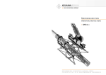
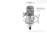
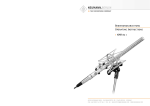
neumann.berlin
the microphone company
Bedienungsanleitung
Operating Instructions
series 180
georg neumann gmbh · ollenhauerstr. 98 · 13403 berlin · germany
fon +49 (0)30 / 41 77 24-0 · fax -50 · [email protected] · www.neumann.com
Series 180
Inhaltsverzeichnis
Table of Contents
1.
Kurzbeschreibung
1.
Summarized Description
2.
Stromversorgung und Kabel
2.
Power Supply and Cables
2.1
Phantomspeisung
2.1
Phantom Powering
2.2
Betrieb mit Netzgeräten
2.2
Ac Supply Operation
2.3
Batteriespeisung
2.3
Battery Operation
2.4
Betrieb an unsymmetrischen oder mittengeerdeten Eingängen
2.4
Operation with Unbalanced or Center Tap
Grounded Inputs
2.5
Kabel
2.5
Cables
3.
Technische Daten
3.
Technical Specifications
4.
Frequenzgänge und Polardiagramme
4.
Frequency Responses and Polar Patterns
5.
Einige Hinweise zur Pflege von Mikrophonen
5.
Hints on Microphone Maintenance
6.
Zubehör
6.
Accessories
2.
1.
2
Kurzbeschreibung
1.
Summarized Description
Die „Series 180“-Kondensator-Kleinmikrophone
verwenden die „fet 100 ®“-Technik. Sie besitzen
eine transformatorlose Mikrophonschaltung und
Kapseln mit den Richtcharakteristiken Kugel
(KM 183), Niere (KM 184) und Hyperniere (KM 185).
The “Series 180” condenser miniature microphones use the “fet 100®” technique with a transformerless microphone circuit and capsules with
omnidirectional (KM 183), cardioid (KM 184) and
hypercardioid (KM 185) pick-up patterns.
Diese Serie zeichnet sich aus durch
This series features
• besonders niedriges Eigengeräusch und höchste Aussteuerbarkeit,
• exceptionally low inherent self-noise and highest overload capability
• das bewährte transformatorlose „fet 100 ® “Schaltungskonzept
• the reliable transformerless “fet 100®” circuit
design
• besonders saubere, freie und verfärbungsfreie
Klangübertragung,
• exceptionally clear sound reproduction free of
coloration
• sehr gleichmäßige, zur 0°-Schalleinfallsrichtung parallele Frequenzkurven bei den Druckgradienten-Empfängern KM 184 und KM 185.
Damit wird der Aufnahmesektor bis ± 135° ohne
Klangfärbungen übertragen.
• very smooth frequency curves, matching 0°
sound incidence, with the pressure-gradient
transducers KM 184 and KM 185. Signals within a pick-up angle of ± 135° are reproduced
without any coloration.
Das Mikrophon hat einen symmetrischen Ausgang.
Der 3-polige XLR-Steckverbinder hat folgende Belegung:
The microphone has a balanced output. The 3-pin
XLR connector has the following pin assignments:
Pin 1: 0 V/Masse
Pin 1: 0 V/ground
Pin 2: Modulation (+Phase)
Pin 2: Modulation (+phase)
Pin 3: Modulation (–Phase)
Pin 3: Modulation (–phase)
Die Mikrophone werden jeweils mit 48 V, 3,2 mA
phantomgespeist (IEC 1938). Der Dynamikumfang
reicht je nach Modell von ca. 13 dB-A (Ersatzgeräuschpegel) bis ca. 138 dB SPL (Grenzschalldruckpegel). Das sind 122 dB.
The microphones operate each on 48 V phantom
power (IEC 1938), supply current 3.2 mA. The dynamic range is 122 dB, from app. 13 dB-A (equivalent SPL) to app. 138 dB SPL (max. SPL).
Die Mikrophone können in folgenden Ausführungsformen geliefert werden:
The microphones are available in the following
versions:
KM 183 ..............
KM 183 mt .........
KM 184 ..............
KM 184 mt .........
KM 185 ..............
KM 185 mt .........
08437
08438
08439
08389
08440
08441
KM 183 .............. ni ............... Cat. No. 08437
KM 183 mt ......... blk ............. Cat. No. 08438
KM 184 .............. ni ............... Cat. No. 08439
KM 184 mt ......... blk ............. Cat. No. 08389
KM 185 .............. ni ............... Cat. No. 08440
KM 185 mt ......... blk ............. Cat. No. 08441
Im Lieferumfang enthalten sind jeweils ein Stativgelenk SG 21/17 mt sowie ein Windschutz WNS 100
in schwarz.
The SG 21/17 mt swivel mount and the WNS 100
windscreen (black) are included in the supply
schedule.
ni ............. Best.-Nr.
sw ............ Best.-Nr.
ni ............. Best.-Nr.
sw ............ Best.-Nr.
ni ............. Best.-Nr.
sw ............ Best.-Nr.
Stromversorgung und Kabel
2.1 Phantomspeisung
2.
Power Supply and Cables
2.1 Phantom Powering
Die „Series 180“-Mikrophone werden mit 48 V
phantomgespeist (P48, IEC 1938).
The “Series 180” microphones operate on 48 V
phantom power (P48, IEC 1938).
Bei der Phantomspeisung fließt der Speisestrom
vom positiven Pol der Spannungsquelle über die
elektrische Mitte der beiden Modulationsadern
zum Mikrophon. Er wird hierzu über zwei gleichgroße Widerstände beiden Tonadern gleichsinnig
zugeführt. Die Rückleitung des Gleichstroms erfolgt über den Kabelschirm. Zwischen beiden Modulationsadern besteht also keine Potentialdifferenz. Daher ist mit der Phantomspeisung eine kompatible Anschlusstechnik möglich:
With phantom powering the dc from the positive
supply terminal is divided via two identical resistors, one half of the dc flowing through each audio (modulation) conductor to the microphone, and
returning to the voltage source via the cable
shield. Phantom powering provides a fully compatible connecting system, since no potential differences exist between the two audio conductors.
Auf die Anschlussdosen können wahlweise auch
dynamische Mikrophone oder Bändchenmikrophone sowie die Modulationskabel röhrenbestückter
Kondensatormikrophone geschaltet werden, ohne
dass die Speisegleichspannung abgeschaltet werden muss.
Der Ausgang eines Neumann-Phantomspeisegerätes darf auch auf bereits anderweitig phantomgespeiste Mikrophoneingänge gesteckt werden.
2.2 Betrieb mit Netzgeräten
Für die Stromversorgung sind alle P48-Netzgeräte geeignet, die mindestens 3,2 mA je Kanal abgeben.
Studio outlets so powered will therefore also accept dynamic microphones and ribbon microphones as well as the modulation conductors of
tube-equipped condenser microphones without the
need to switch off the dc supply voltage.
No harm is done even if a Neumann phantom power supply is connected to the inputs of microphones which are phantom powered from another
source.
2.2 ac Supply Operation
All P48 power supplies in accordance with
IEC 1938 which provide at least 3.2 mA per
channel, are suitable for powering the microphones.
3
Series 180
Das Neumann P48-Netzgerät hat die Bezeichnung
N 248. Es ist zur Stromversorgung zweier MonoKondensatormikrophone oder eines Stereomikrophons mit 48 V ± 1 V, maximal 2 x 6 mA, geeignet
(siehe auch Neumann-Druckschrift 68832: „48 VPhantomspeisegeräte“).
The Neumann P48 power supply unit bears the
designation N 248. It is designed to power two
mono condenser microphones or one stereo microphone at 48 V ± 1 V, max. 2 x 6 mA (see also Neumann bulletin no. 68832: ”Phantom 48 VDC Power Supplies“).
Die Zuordnung der Mikrophonanschlüsse und die
Polarität der Modulationsadern ist am Ausgang
des Speisegerätes die gleiche wie am Mikrophon.
The assignment of the microphone terminals and
the modulation polarity at the power supply output are identical to those at the microphone.
Das Netzgerät N 248 versorgt ein oder zwei Mikrophone mit 48 V-Phantomspeisung P48. Alle Anschlüsse mit XLR 3-Flanschdosen. Die Modulationsausgänge sind gleichspannungsfrei.
The N 248 supplies one stereo microphone, or two
mono condenser microphones with 48 V phantom
power (P48). All connectors are of XLR 3 type. The
audio signal outputs are DC-free.
Das Gerät ist in drei Ausführungen erhältlich:
Three versions are available:
N 248 EU ............ sw ............ Best.-Nr. 08537
N 248 US ............ sw ............ Best.-Nr. 08538
N 248 UK ............ sw ............ Best.-Nr. 08539
N 248 EU ............ blk ............. Cat. No. 08537
N 248 US ............ blk ............. Cat. No. 08538
N 248 UK ............ blk ............. Cat. No. 08539
2.3 Batteriespeisung
Steht keine Netzspannung zur Verfügung, kann die
Speisung mit einem der Geräte
If a mains power source is not available, power
can be supplied by one of the battery units
BS 48 i .................................. Best.-Nr. 06494
(für ein Mikrophon)
BS 48 i .................................... Cat. No. 06494
(for one microphone)
BS 48 i-2 ............................... Best.-Nr. 06496
(für zwei Mikrophone)
BS 48 i-2 ................................. Cat. No. 06496
(for two microphones)
erfolgen. Beide Geräte liefern 48 V ± 1 V, maximal
je 5 mA, und werden jeweils von einer 9 VoltBlockbatterie Typ IEC 6 F 22 gespeist.
Both units deliver 48 V ± 1 V, at 5 mA maximum,
and are powered by a 9-volt monobloc battery
Type IEC 6 F 22.
Das Gerät BS 48 i-2 ist mit 5-poligen, das BS 48 i
mit 3-poligen XLR-Steckverbindern ausgerüstet.
The BS 48 i-2 is equipped with 5-pin XLR connectors, the BS 48 i with 3-pin XLR connectors.
Ein „Series 180“-Kleinmikrophon kann mit einem
BS 48 i mindestens 20 Stunden betrieben werden.
(Siehe auch Neumann-Druckschrift 68832... „48 VPhantomspeisegeräte“).
A „Series 180“ miniature microphone can be operated for at least 20 hours on a BS 48 i. (See
Neumann bulletin 68832... “Phantom 48 VDC Power Supplies”.)
Die Zuordnung der Mikrophonanschlüsse und die
Polarität der Modulationsadern ist am Ausgang der
Speisegeräte die gleiche wie am Mikrophon.
The assignment of the microphone terminals and
the modulation polarity at the power supply output are identical to those at the microphone.
2.4 Betrieb an unsymmetrischen oder
mittengeerdeten Eingängen
Die 48 V-Phantom-Speisegeräte BS 48 i, BS 48 i-2
und N 248 haben gleichspannungsfreie Ausgänge,
so dass für den Anschluss an unsymmetrische Eingänge kein Übertrager erforderlich ist.
4
2.3 Battery Powering
Bei den Mikrophonen ist Pin 2 normgemäß die
„heiße Phase“. Für unsymmetrische Eingänge muss
PIN 3 am Ausgang des Speisegerätes an Masse
gelegt werden (siehe Abbildung 1).
In the microphones pin 2 is the “hot phase“, in accordance with the standard, and pin 3 of the output of the power supply must be connected to
earth (see Fig. 1).
Bei vielen anderen als den o.g. Phantomspeisegeräten liegen nicht nur die Modulationsleitungen
zum Mikrophon auf dem Potential der Speisespannung von +48 V, sondern auch die vom Speisegerät abgehenden Modulationsleitungen. Für die in
der Studiotechnik allgemein üblichen symmetrischen und erdfreien Verstärker und Mischpulteingänge ist dies ohne Bedeutung. Dagegen wird die
Speisespannung beim Anschluss an einseitig oder
mittengeerdete Verstärkereingänge kurzgeschlossen, und es ist kein Betrieb möglich. Dann bestehen folgende Lösungsmöglichkeiten:
In the case of many other phantom powering units
(except those mentioned above), not only the modulation leads to the microphone, but also the outgoing modulation leads from the powering unit,
are at the potential of the feed voltage (+48 V).
This is of no significance for the balanced, floating amplifier and mixing console inputs in general studio use. On the other hand, the feed voltage
will be short-circuited when connected to singleended or center tap grounded amplifier inputs, and
no operation will be possible. This can be circumvented as follows:
a) In mittengeerdeten Geräten mit Eingangsübertrager (z.B. einige NAGRA-Geräte) kann die
betreffende Erdverbindung fast immer ohne Nachteile für die Funktion des
Gerätes aufgetrennt werden.
a) In center tap grounded equipment with input
transformer (e.g. some NAGRA units), the earth
lead can almost always be disconnected without
affecting the function of
the equipment.
b) In jede abgehende
Modulationsleitung kann
zur Abblockung der 48 VGleichspannung eine RCKombination eingefügt
werden (siehe Abbildung 2 und Neumann-Information Nr. 84 221).
b) In every outgoing
modulation lead, an RC
net-work can be incorporated to block the 48 Vdc
voltage (See Figure 2 and
Neumann-Information no.
84 222).
Abbildung / Figure 1
2.4 Operation with Unbalanced or
Center Tap Grounded lnputs
The BS 48 i, BS 48 i-2 and N 248 phantom 48 Vdc
power supplies are dc-free so that no transformer
is required for connection to unbalanced inputs.
Abbildung / Figure 2
5
Series 180
2.5 Mikrophonkabel
6
2.5 Microphone Cables
Die akustischen Eigenschaften der Mikrophone
werden auch durch sehr lange (Neumann-) Kabel
nicht beeinflusst. Erst bei Kabellängen deutlich
über 300 m macht sich ein Abfall im oberen Frequenzbereich bemerkbar.
The electroacoustic properties of the microphones
are not affected even by very long (Neumann) cables. However, if cables are well over 300 m, a
fall-off in the upper frequency range becomes apparent.
Neumann bietet ein vielfältiges Kabelsortiment
an, von dem hier ein Ausschnitt erwähnt wird. Andere als die genannten Kabellängen sowie Kabelmaterial ohne Armaturen sind auf Wunsch lieferbar.
Neumann offers a wide range of cables. Only a selection is presented here. Other cable lengths or
cable materials without connectors are available
on request.
IC 3 mt ............... sw ............ Best.-Nr. 06543
Mikrophonkabel mit Doppeldrallumspinnung als
Abschirmung. Ø 5 mm, Länge 10 m. XLR 3 Steckverbinder, schwarzmatt.
IC 3 mt ................ blk ............. Cat. No. 06543
Microphone cable with double twist (double helix)
braiding as shield. Ø 5 mm, length 10 m. XLR 3
connectors, matte black.
IC 31 mt (5 m) ... sw ............ Best.-Nr. 06570
Mikrophonkabel mit Doppeldrallumspinnung als
Abschirmung. Textilumsponnen, zur Vermeidung
von Reibgeräuschen bei der Verwendung an Mikrophonangel oder Windschutzkorb. Ø 4,5 mm,
Länge 5 m. XLR 3 Steckverbinder, schwarzmatt.
IC 31 mt (5 m) .... blk ............. Cat. No. 06570
Microphone cable with double twist (double helix) braiding as shield. Textile-braided to avoid
frictional noise due to the handling of booms or
plastic leadings (for example in windscreens).
Ø 4,5 mm, length 5 m. XLR 3 connectors, matte
black.
AC 22 (0,3 m) ...................... Best.-Nr. 06598
Adapterkabel mit XLR 5 F-Buchse und 3,5 mm Stereoklinkenstecker, unsymmetrisch, für den Anschluss des XLR 5-Ausganges des Speisegerätes
BS 48 i-2 oder der Matrixbox MTX 191 A an Geräte mit 3,5 mm Stereoklinkenbuchse. Für alle Mikrophone außer der Ausgangsstufe KM 100 und des
GFM 132.
AC 22 (0.3 m) ......................... Cat. No. 06598
Adapter cable with XLR 5 M connector and unbalanced 3.5 mm stereo jack. It is used to connect the
5-pin XLR output of the BS 48 i-2 power supply or
the MTX 191 A matrix amplifier to units with a
3.5 mm stereo input. It is designed for all microphones of the fet 80/100 series and KM 100 F, excluding the KM 100 and the GFM 132.
AC 25 (0,3 m) ...................... Best.-Nr. 06600
Adapterkabel mit XLR 3 F-Buchse und 6,3 mm Monoklinkenstecker, unsymmetrisch, für den Anschluss des 3-poligen XLR-Ausganges eines Speisegerätes an Geräte mit 6,3 mm Monoklinkenbuchse. Für alle Mikrophone mit Ausnahme der
Ausgangsstufe KM 100 und des GFM 132.
AC 25 (0.3 m) ......................... Cat. No. 06600
Adapter cable with XLR 3 M connector and unbalanced 6.3 mm mono jack. It is used to connect
3-pin XLR outputs of power supplies to units with
a 6.3 mm monojack input. Designed for all microphones, excluding KM 100 System and GFM 132.
AC 27 (0,3 m) ...................... Best.-Nr. 06602
Y-Kabel mit einer XLR 5 F-Buchse und zwei 6,3 mm
Monoklinkensteckern, unsymmetrisch, für den Anschluss des XLR 5-Ausganges des Speisegerätes
BS 48 i-2 oder der Matrixbox MTX 191 A an Geräte mit 6,3 mm Monoklinkenbuchsen. Für alle Mikrophone mit Ausnahme von KM 100 und
GFM 132.
AC 27 (0.3 m) ......................... Cat. No. 06602
Y-cable with XLR 5 M connector and two unbalanced 6.3 mm mono jacks. It is used to connect
XLR 5 outputs of the BS 48 i-2 power supply or the
MTX 191 A matrix amplifier to units with 6.3 mm
monojack inputs. Designed for all microphones,
excluding KM 100 System and GFM 132.
3.
Technische Daten
3.
Technical Specifications
Akust. Arbeitsweise ....... Druck-/Druckgradientenempfänger
Acoustical op. principle ............. Pressure/Pressure
gradient transducer
Richtcharakteristik ......... Kugel/Niere/Hyperniere
Polar pattern ................ Omnidirectional/Cardioid
Hypercardioid
Übertragungsbereich .................... 20 Hz...20 kHz
Frequency range .......................... 20 Hz...20 kHz
Feldübertragungsfaktor1) .............................. 12/15/10 mV/Pa ± 1 dB
Sensitivity1) ..................... 12/15/10 mV/Pa ± 1 dB
Nennimpedanz ....................................... 50 Ohm
Rated impedance ................................... 50 ohms
Nennabschlußimpedanz ...................... 1000 Ohm
Rated load impedance ....................... 1000 ohms
Geräuschpegelabstand2),
CCIR3) ........................................... 70/72/70 dB
Signal-to-noise ratio2),
CCIR3) ........................................... 70/72/70 dB
Geräuschpegelabstand2),
A-bewertet3) ................................. 81/81/79 dB
Signal-to-noise ratio2),
A-weighted3) ................................. 81/81/79 dB
Ersatzgeräuschpegel,
CCIR3) ........................................... 24/22/24 dB
Equivalent noise level,
CCIR3) ........................................... 24/22/24 dB
Ersatzgeräuschpegel,
A-bewertet3) ............................. 13/13/15 dB-A
Equivalent noise level,
A-weighted3) ............................. 13/13/15 dB-A
Grenzschalldruckpegel für
0,5 % Klirrfaktor4) .................. 140/138/142 dB
Maximum SPL
for less than 0.5 % THD4) ........ 140/138/142 dB
Max. Ausgangsspannung .......................... 10 dBu
Max. output voltage ................................. 10 dBu
Speisespannung5)
.............................. 48 V ± 4 V
Supply voltage5) ................................ 48 V ± 4 V
Stromaufnahme5) ..................................... 3,2 mA
Current consumption5) .............................. 3.2 mA
Erforderlicher Steckverbinder ................... XLR 3F
Matching connector .................................. XLR 3F
Gewicht ................................................. ca. 80 g
Weight ............................................ approx. 80 g
Abmessungen ........................ Ø 22 mm x 107 mm
Dimensions ........................... Ø 22 mm x 107 mm
94 dB SPL 1 Pa = 10 µbar
0 dB 20 µPa
94 dB SPL 1 Pa = 10 µbar
0 dB 20 µPa
1)
bei 1 kHz an 1 kOhm Nennlastimpedanz.
1)
at 1 kHz into 1 kohms rated load impedance.
2)
bezogen auf 94 dB SPL
2)
re 94 dB SPL
3)
nach IEC 60268-1;
CCIR-Bewertung nach CCIR 468-3, Quasi-Spitzenwert;
A-Bewertung nach IEC 61672-1, Effektivwert
3)
according to IEC 60268-1;
CCIR-weighting acccording to CCIR 468-3, quasi peak;
A-weighting according to IEC 61672-1, RMS
4)
Klirrfaktor des Mikrophonverstärkers bei einer Eingangsspannung, die der von der Kapsel beim entsprechenden
Schalldruck abgegebenen Spannung entspricht.
4)
THD of microphone amplifier at an input voltage equivalent
to the capsule output at the specified SPL.
5)
Phantom powering (P48, IEC 1938).
5)
Phantomspeisung (P48, IEC 1938).
7
Series 180
4.
Frequenzgänge und Polardiagramme
Frequency Responses and Polar Patterns
KM 183
gemessen im freien Schallfeld nach IEC 60268-4
measured in free-field conditions (IEC 60268-4)
KM 184
KM 185
8
9
Series 180
5.
Einige Hinweise zur Pflege von
Mikrophonen
Hints on Microphone Maintenance
Staubschutz verwenden: Mikrophone, die nicht im
Einsatz sind, sollte man nicht auf dem Stativ einstauben lassen. Mit einem Staubschutzbeutel
(nicht fusselnd) wird dies verhindert. Wird ein Mikrophon längere Zeit nicht verwendet, sollte es
staubgeschützt bei normalem Umgebungsklima
aufbewahrt werden.
Use a dust cover: Microphones not in use should
not be left on the stand gathering dust. This can
be prevented by the use of a non-fluffy dust cover. When not in use for a longer period, the microphone should be sealed against dust and stored
under standard climatic conditions.
Popschutz verwenden: Ein Popschutz hat nicht nur
die Aufgabe, bei Gesangsaufnahmen die Entstehung von Poplauten zu verhindern. Er vermeidet
auch effizient, dass sich von der Feuchtigkeit des
Atems bis hin zu Essensresten unerwünschte Partikel auf der Membran ablagern.
Use a pop screen: A pop screen not only prevents
the occurrence of plosive pop noises in vocal recordings, but also efficiently prevents unwanted
particles, from respiratory moisture to food remnants, from settling on the diaphragm.
Keine überalterten Windschutze verwenden: Auch
Schaumstoff altert. Das Material kann brüchig und
krümelig werden. Anstatt das Mikrophon zu schützen, kann er dann zur Verunreinigung der Mikrophonkapsel führen. Überalterte Windschutze also
bitte entsorgen.
Avoid the use of old wind shields: As the foam
material of a wind shield ages it can become brittle and crumbly. Instead of protecting the microphone, an old wind shield can thus lead to soiling
of the microphone capsule. Therefore please dispose of worn-out wind shields.
Funktionstest: Moderne Kondensatormikrophone
nehmen durch lautes Ansprechen keinen Schaden.
Zur Kontrolle, ob ein solches Mikrophon angeschlossen ist, sollte man es aber keinesfalls anpusten oder anpoppen, da dies einem akustischen Signal von mehr als 140 dB (!) entsprechen kann.
Normale Sprache genügt zum Funktionstest völlig.
Function testing: Although modern condenser microphones are not harmed by high sound pressure
levels, one should under no circumstances use a
pop-test to check whether the microphone is connected and the channel on the mixing console is
pulled up, since this can result in sound pressure
levels of over 140 dB! Normal speech is quite sufficient for function testing.
Selbsthilfe kann teuer sein! Leider kommt es doch
vor, dass durch eine Selbstreparatur mehr beschädigt als behoben wird. Insbesondere das Reinigen
verschmutzter Kapseln erfordert viel Erfahrung und
die Hand eines Fachmanns. Der Lackschutz auf
Platinen zeigt u.a. an, dass dort nicht gelötet werden darf. Einige Bauteile sind speziell selektiert
und können nicht durch Material von der Stange
ersetzt werden. Um unnötige Kosten zu vermeiden,
empfiehlt sich die Einsendung an unsere Vertretungen oder an uns.
Inspektion durchführen lassen: Regelmäßiges
Durchchecken des Mikrophonbestands, wie es einige Schauspielhäuser und Rundfunkanstalten
praktizieren, kann bei der Früherkennung von
Schäden helfen. Leichte Verschmutzungen lassen
sich eher beseitigen, als eine untrennbar in die
Membran eingebrannte Nikotinschicht. Insbesondere bei Mikrophonen im Verleih und in verunreinigenden Umgebungen empfiehlt sich die regelmäßige Kontrolle, deren Kosten im Vergleich zu
einer aufwendigen Reparatur sehr gering sind.
10
5.
Do-it-yourself repairs can be expensive! Unfortunately, do-it-yourself repairs sometimes do more
harm than good. Cleaning soiled capsules in particular requires considerable experience and an
expert touch. The protective lacquer on circuit
boards indicates, among other things, places
which must not be soldered. Certain components
are specially selected and cannot be replaced by
standard parts. To avoid unnecessary expense, we
recommend sending defective microphones to us
or our representatives for servicing.
Regular inspections: Sending in microphones regularly for inspection, as practiced by some theaters
and broadcasting corporations, can aid in the early detection of damage. Slight soiling can be removed much more easily than a nicotine layer inextricably bonded to the diaphragm. Regular inspections are particularly to be recommended for
microphones which are rented or are used in dusty
or smoky environments, since the costs are low in
comparison with the cost of a major overhaul.
6.
Zubehör*)
6.
Accessories *)
Stativgelenke und mechanische Adapter
Stand Mounts and Mechanical Adapter
SG 21/17 mt ....... sw ............ Best.-Nr. 06149
(gehört zum Lieferumfang)
Das Stativgelenk SG 21/17 mt besitzt eine Kunststoffklammer zur Aufnahme von Kleinmikrophonen. Es hat einen Gewindeanschluss 5/8"-27Gang, mit Adapter für 1/2"- und 3/8"-Stative. Eine
weitere Klammer mit 17 mm Durchmesser wird
mitgeliefert. Damit kann das Mikrophon am Steckverbinder gehalten werden.
SG 21/17 mt ....... blk ............. Cat. No. 06149
(included in the supply schedule)
Swivel mount with a plastic clamp for miniature
microphones. It has a 5/8"-27 female thread, plus
a thread adapter to connect to 1/2"- and 3/8"
stands. An additional clamp, Ø 17 mm, is included
for use when the microphone should be held more
elegantly at the XLR connector.
DS 21 mt ............. sw ............ Best.-Nr. 06798
Das Doppelstativ DS 21 mt wurde konstruiert, um
zwei Kleinmikrophone an einem Ort einfach und
übersichtlich anzuordnen.
DS 21 mt ............. blk ............. Cat. No. 06798
The DS 21 mt is designed for applications where
two miniature microphones are used simultaneously in one location.
Es läßt sich auf Tisch- und Fußbodenständern
ebenso wie an Galgen montieren. Damit steht
auch für alle die Anwendungen, bei denen zum
Beispiel aus Gründen der Funktionssicherheit
grundsätzlich ein zweites Mikrophon am gleichen
Ort einsatzbereit sein muß, ein vorzügliches Hilfsmittel zur Verfügung.
It can be mounted equally easily on a table or
floor stand or on a boom. This is a real advantage
in all situations where, for instance, a second microphone must be ready for use at all times at a
particular location.
The DS 21 mt has a 5/8"-27 female thread, plus a
thread adapter to connect to 1/2"- and 3/8" stands.
Es hat einen Gewindeanschluss 5/8"-27-Gang, mit
Adapter für 1/2"- und 3/8"-Stative.
DS 120 ............... sw ............ Best.-Nr. 07343
Das DS 120 hat eine 150 mm lange Schiene, mit
zwei verschiebbaren 1/2"-Gewindeschrauben zur
Befestigung zweier Mikrophone in ihren Halterungen. Abstand und Winkel für die Anordnung der
Mikrophone sind wählbar. Der Gewindeanschluss
hat 5/8"-27-Gang, mit Adapter für 1/2"- und 3/8"Stative.
DS 120 ............... blk ............. Cat. No. 07343
The DS 120 has a 150 mm long support bar with
two movable 1/2" threaded studs. Two microphones in their mounts can be attached. Any space
or angle between the microphones is freely adjustable. The DS 120 has a 5/8"-27 female thread,
plus a thread adapter to connect to 1/2"- and 3/8"
stands.
Tisch- und Fußbodenständer
Table and Floor Stands
MF 2 ................... sw ............ Best.-Nr. 07266
Kleiner Tischständer mit Messingfuß, sehr standsicher. Der Ständer ist schwarzmatt lackiert und
steht gleitfest auf einer Moosgummischeibe. Der
1/2"-Gewindezapfen zur Aufnahme z.B. des Stativgelenkes SG 21/17 mt ist zur Körperschallunterdrückung durch ein Gummielement vom Fuß entkoppelt. Ø 60 mm, Gewicht 340 g.
MF 2 ................... blk ............. Cat. No. 07266
Small table stand with brass base, very sturdy. It
has a black matte finish. The bottom is fitted with
a non-slip rubber disk. The stand has a 1/2"
threaded stud for mounting the SG 21/17 mt, for example. The rubber shock mount between the stud
and the base serves to suppress structure-borne
noise. Ø 60 mm, Weight 340 g.
11
Series 180
12
MF 3 ................... sw ............ Best.-Nr. 07321
Der Mikrophonfuß MF 3 ist ein Tischständer mit
Eisenfuß, 1,6 kg schwer, Durchmesser 110 mm. Der
Ständer ist schwarzmatt lackiert und steht gleitfest auf einer Moosgummischeibe. Ein umwendbarer Gewindezapfen und ein mitgeliefertes Reduzierstück ermöglichen die Verwendung für 1/2"und 3/8"-Gewindeanschlüsse.
MF 3 ................... blk ............. Cat. No. 07321
The MF 3 is a table stand with iron base, 1.6 kg in
weight, 110 mm in diameter. It has a black matte
finish. The bottom is fitted with a non-slip rubber
disk. The stand comes with a reversible stud and
an adapter for 1/2" and 3/8" threads.
MF 4 ................... sw ............ Best.-Nr. 07337
Der Mikrophonfuß MF 4 ist ein Fußbodenständer
aus Grauguss, ca. 2,6 kg schwer, Ø 160 mm. Der
Ständer ist schwarzmatt lackiert und steht gleitfest auf einem Gummiring. Ein umwendbarer Gewindezapfen und ein mitgeliefertes Reduzierstück
ermöglichen die Verwendung für 1/2"- und 3/8"Gewindeanschlüsse.
MF 4 ................... blk ............. Cat. No. 07337
Floor stand with grey cast iron base. The floor
stand has a matt black finish and rests on a nonskid rubber disk attached to the bottom. A reversible stud and a reducer for 1/2" and 3/8" threads
are also supplied. Weight 2.6 kg, Ø 160 mm.
MF 5 ................... gr ............. Best.-Nr. 08489
Der Mikrophonfuß MF 5 hat eine graue Soft-Touch
Pulverbeschichtung und steht gleitfest und trittschalldämmend auf einem Gummiring. Der Stativanschluss hat ein 3/8"-Gewinde. Gewicht 2,7 kg,
Ø 250 mm.
MF 5 ................... gr ............... Cat. No. 08489
Floor stand with grey soft-touch powder coating.
It has a non-skid sound-absorbing rubber disk attached to the bottom. The stand connection has a
3/8" thread. Weight 2.7 kg, Ø 250 mm.
STV 4 .................. sw ............ Best.-Nr. 06190
STV 20 ............... sw ............ Best.-Nr. 06187
STV 40 ............... sw ............ Best.-Nr. 06188
STV 60 ............... sw ............ Best.-Nr. 06189
Die Stativverlängerungen STV ... werden zwischen
Mikrophonständer (z.B. MF 4, MF 5) und Stativgelenk (z.B. SG 21/17 mt) geschraubt.
STV 4 .................. blk ............. Cat. No. 06190
STV 20 ............... blk ............. Cat. No. 06187
STV 40 ............... blk ............. Cat. No. 06188
STV 60 ............... blk ............. Cat. No. 06189
The STV... stand extensions are screwed between
microphone stands (for example MF 4, MF 5) and
swivel mounts (for example SG 21/17 mt).
Die STV ... haben eine Länge von 40, 200, 400
oder 600 mm. Ø 19 mm.
Length 40, 200, 400 or 600 mm. Ø 19 mm.
Mikrophonangel
Microphone Fishpole
MA (+ EA 2124 A mt) ... sw ... Best.-Nr. 06771
Die Mikrophonangel besteht aus Carbon- und Glasfiber. Sie kann auf jede gewünschte Arbeitslänge
bis 4,2 m ausgezogen werden. Die Transportlänge
beträgt 1,3 m, das Gewicht 0,5 kg.
Die Angel hat einen 3/8" Gewindezapfen. An der
Angel befindet sich eine Elastische Aufhängung
EA 2124 A mt (im Lieferumfang enthalten) zur
Aufnahme von Mikrophonen mit 21 mm bis 24 mm
Durchmesser.
MA (+ EA 2124 A mt) ... blk .... Cat. No. 06771
The microphone fishpole is made of carbon material and fiberglass. It can be extended to 4.2 m. For
storage its length is 1.3 m, the weight 0.5 kg.
The MA has a 3/8" threaded stud. The fishpole
comes with an attached elastic suspension, EA
2124 A mt, suitable to hold microphones between
21 mm and 24 mm in diameter.
Schwanenhälse
Goosenecks
SMK 8 i ............... sw ............ Best.-Nr. 06181
Der Schwanenhals SMK 8 i hat eine Länge von
360 mm und dient zum elektrischen und mechanischen Anschluss eines Mikrophons mit XLR 3 MStecker. Eine Kontermutter arretiert das Mikrophon
klapperfrei und bietet einen gewissen Diebstahlschutz. Der Kabelaustritt ist seitlich über dem Gewindeanschluss. Kabellänge 4,5 m, Kabelstecker
XLR 3 M. Gewindeanschluss: 5/8"-27-Gang, mit
Adapter für 1/2"- oder 3/8"-Stative.
SMK 8 i ............... blk ............. Cat. No. 06181
The SMK 8 i gooseneck is 360 mm long and serves
as electrical and mechanical connection of a microphone with XLR 3 connector. A counter nut secures the microphone against rattle and – to a certain extent – against theft. The cable comes out at
the side, just above the bottom thread. Cable
length 4.5 m, cable connector XLR 3 M. The gooseneck has a 5/8"-27 female thread, plus a thread
adapter to connect to 1/2" and 3/8" stands.
Mikrophonneigevorrichtungen
Auditorium Hangers
MNV 21 mt .......... sw ............ Best.-Nr. 06802
Die Neigevorrichtung ermöglicht die Einstellung
der Mikrophonneigung bei frei am Kabel hängendem Mikrophon. Die MNV 21 mt besteht aus einer
schwenkbaren Klammer zur Aufnahme eines Kleinmikrophons oder KMR 81 und aus einer Kabelführung mit Drehverschluss.
MNV 21 mt .......... blk ............. Cat. No. 06802
The auditorium hanger adjusts the tilting angle of
a microphone suspended by its own cable. The
MNV 21 consists of the tilting clamp, suitable to
hold a Neumann miniature microphone or KMR 81,
and a locking cable strain relief.
Die MNV 21 mt ermöglicht die Einstellung der
Mikrophonneigung bei frei am Kabel hängendem
Mikrophon.
The MNV 21 mt allows the microphone tilt to be
adjusted with the microphone freely suspended
from its own cable.
Elastische Aufhängung
Elastic Suspension
Um mechanische Erschütterung fernzuhalten, empfiehlt sich die Verwendung einer elastischen Mikrophonaufhängung.
Elastic suspension is recommended to prevent the
microphone from being exposed to strong mechanical vibrations caused by structure borne shock
waves.
EA 2124 A mt ...... sw ............ Best.-Nr. 08433
Die EA 2124 A mt kann Mikrophone mit Durchmessern von 21 bis 24 mm aufnehmen. Der schwenkbare Gewindeanschluss hat 5/8"-27-Gang, mit Adapter für 1/2"- und 3/8"-Stative.
EA 2124 A mt ...... blk ............. Cat. No. 08433
The EA 2124 A mt is able to accept microphones
from 21 to 24 mm in diameter. It has a swivel
mount with a 5/8"-27 female thread, plus a thread
adapter to connect to 1/2"- and 3/8" stands.
Windschirme
Windshields
Zum Vermeiden von Störgeräuschen, die bei Nahbesprechung, Windeinfluss oder z.B. bei schnellem
Schwenken des Mikrophongalgens auftreten können, sind Windschutzeinrichtungen aus offenporigem Polyurethanschaum lieferbar. Diese Windschirme erzeugen keine störenden Resonanzen.
Close range sounds, wind, and fast movements of
the microphone boom, all may cause interfering
noises. To avoid these unwanted sounds, windscreen accessories are available. Typically, they
are made out of open-cell polyurethane foam.
These windscreens do not cause interfering reso-
13
Series 180
14
Sie beeinflussen die Richtcharakteristik und das
Übertragungsmaß im oberen Frequenzbereich nur
geringfügig.
nances and do not influence the directional pattern. Only in the upper frequency range is the output level slightly attenuated.
Die Dämpfung des Windgeräusches wurde ohne
elektrischen Filter gemessen, in verwirbelter
Luftströmung der Geschwindigkeit 20 km/h, erzeugt von einer geräuschlos arbeitenden Windmaschine.
The wind noise attenuation was measured without electrical filtering in a turbulent air stream
traveling at 20 km/h, generated by a noiseless
wind machine.
WNS 100 ............. sw ............ Best.-Nr. 07323
(gehört zum Lieferumfang)
WNS 100 ............. blk ............. Cat. No. 07323
(included in the supply schedule)
WNS 100 ............. rt ............. Best.-Nr. 07324
WNS 100 ............. gn ............ Best.-Nr. 07325
WNS 100 ............. ge ............ Best.-Nr. 07326
WNS 100 ............. bl ............. Best.-Nr. 07327
WNS 100 ............. ws ............ Best.-Nr. 07328
Windschutz für KM 100 und Series 180. Dämpfung
des Windgeräusches 18 dB. Dämpfung bei 15 kHz
2 dB. Ø 45 mm.
WNS 100 ............. red ............. Cat. No. 07324
WNS 100 ............. green ......... Cat. No. 07325
WNS 100 ............. yellow ........ Cat. No. 07326
WNS 100 ............. blue ........... Cat. No. 07327
WNS 100 ............. white .......... Cat. No. 07328
Windscreen for KM 100 and Series 180. Wind noise attenuation 18 dB. Attenuation at 15 kHz 2 dB.
Ø 45 mm.
WNS 110 ............. sw ............ Best.-Nr. 08535
Akustisch transparenter Wind- und Nahbesprechungsschutz für KM 100 und Series 180, mit erhöhter Effizienz. Dämpfung des Windgeräusches
21 dB. Dämpfung bei 15 kHz ca. 1 dB. Ø 45 mm,
Länge 70 mm. Farbe schwarz.
WNS 110 ............. blk ............. Cat. No. 08535
Acoustically transparent wind and pop protection
for KM 100 and Series 180 with improved efficiency. Wind noise attenuation 21 dB. Attenuation at
15 kHz 1 dB. Ø 45 mm, length 70 mm. Color black.
WS 100 ............... sw ............ Best.-Nr. 06751
Windschutz für KM 100 und Series 180. Dämpfung
des Windgeräusches 23 dB. Dämpfung bei 15 kHz
4 dB. Ø 90 mm. Farbe schwarz.
WS 100 ............... blk ............. Cat. No. 06751
Windscreen for KM 100 and Series 180. Wind
noise attenuation 23 dB. Attenuation at 15 kHz
approx. 4 dB. Ø 90 mm. Color black.
Popschutz
Popscreen
Popschirme bieten einen sehr wirksamen Schutz
vor den sogenannten Popgeräuschen. Sie bestehen
aus einem runden, dünnen Rahmen, der beidseitig mit schwarzer Gaze bespannt ist.
Pop screens provide excellent suppression of socalled pop noise. They consist of a round, thin
frame covered with black gauze on both sides.
Popschirme sind an einem etwa 30 cm langen
Schwanenhals montiert. Eine Klammer mit einer
Rändelschraube an dessen Ende dient der Befestigung am Mikrophonstativ.
A gooseneck of about 30 cm (12") in length is
mounted at the popshield. It will be attached to
microphone stands by means of a clamp with a
knurled screw.
PS 15 .................. sw ............ Best.-Nr. 08472
Der Rahmendurchmesser beträgt 15 cm.
PS 15 .................. blk ............. Cat. No. 08472
The frame is 15 cm in diameter.
*)
*)
Weitere Artikel sind im Katalog „Zubehör“ beschrieben.
N 248
BS 48 i
BS 48 i-2
IC 3 mt
IC 31 mt
AC 22
AC 25
AC 27
SG 21/17 mt
DS 21 mt
DS 120
MF 2
Further articles are described in the catalog “Accessories”.
15
MF 3
MF 4
MF 5
SMK 8 i
MNV 21 mt
STV...
EA 2124 A mt
WNS 100
WNS 110
WS 100
PS 15
Konformitätserklärung
Die Georg Neumann GmbH erklärt, dass dieses Gerät die
anwendbaren CE-Normen und -Vorschriften erfüllt.
Declaration of Conformity
Georg Neumann GmbH hereby declares that this device
conforms to the applicable CE standards and regulations.
Irrtümer und technische Änderungen vorbehalten • Errors excepted, subject to changes
Printed in Germany • Publ. 09/05 076833/A06