1
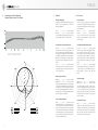
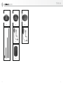
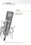
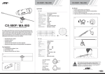
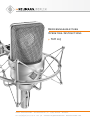
Bedienungsanleitung
Operating Instructions
TLM 103
georg neumann gmbh · ollenhauerstr. 98 · 13403 berlin · germany
tel +49 (0)30 / 41 77 24-0 · fax -50 · [email protected] · www.neumann.com
TLM 103
Inhaltsverzeichnis
Table of Contents
1.
Kurzbeschreibung
1.
A Short Description
2.
Das Kondensatormikrofon TLM 103
2.
The TLM 103 Condenser Microphone
2.1
Ausführungsformen und Beschaltung des
Ausganges
2.1
Microphone Versions
and Output Wiring
Die Buchstaben TLM stehen für Transformatorloses Mikrofon.
2.2
Mikrofonkabel
2.2
Microphone Cables
3.
Stromversorgung
3.
Power Supply
3.1
Phantomspeisung
3.1
Phantom Powering
3.2
Betrieb mit Netzgeräten
3.2
ac Supply Operation
3.3
Batteriespeisung
3.3
Battery Powering
3.4
Betrieb an unsymmetrischen oder
mittengeerdeten Eingängen
3.4
Operation with Unbalanced or Center
Tap Grounded Inputs
Der zur Leistungsanpassung der Mikrofonausgangsspannung an die Betriebsspannung üblicherweise verwendete Übertrager ist im TLM 103
durch eine elektronische Schaltung ersetzt, die –
wie ein Übertrager – für eine gute Unsymmetriedämpfung sorgt. Daher werden Störsignale, die auf
die symmetrische Modulationsleitung einwirken,
wie gewohnt unterdrückt.
4.
Technische Daten
4.
Technical Specifications
5.
Einige Hinweise zur Pflege von Mikrofonen
5.
Some Remarks on Maintenance
6.
Frequenzgang und Polardiagramm
6.
Frequency Response and Polar Pattern
7.
Zubehör
7.
Accessories
1.
Kurzbeschreibung
1.
A Short Description
2
2.
Das Kondensatormikrofon TLM 103
Das Kondensatormikrofon TLM 103 ist ein Studiomikrofon der Serie fet 100 mit der Richtcharakteristik Niere.
Die Eigenstörspannung des TLM 103 konnte gegenüber vergleichbaren Mikrofontypen stark gesenkt werden, wobei das Mikrofon Schalldruckpegel von 138 dB unverzerrt überträgt und einen Dynamikumfang von 131 dB zur Verfügung stellt
(A-bewertet).
Das TLM 103 wird von der Vorderseite besprochen, die durch das Neumann-Logo gekennzeichnet ist.
Die im Drahtgeflechtkorb des Mikrofons befindliche Großmembrankapsel K 103 besitzt einen bis
ca. 5 kHz ebenen Frequenzgang und im darüberliegenden Frequenzbereich eine breite, flache Präsenzanhebung von 4 dB. Die Kapsel basiert auf
der des Mikrofons U 87, indem deren Elektrode
und Membran Verwendung finden.
Das Kondensatormikrofon TLM 103 ist ein Studiomikrofon mit der Richtcharakteristik Niere.
The TLM 103 is a studio condenser microphone
with cardioid polar pattern.
Es zeichnet sich aus durch extrem niedriges Eigengeräusch und höchste Aussteuerbarkeit, transformatorlose Schaltungstechnik, besonders saubere,
freie und verfärbungsfreie Klangübertragung.
Its most important features are extraordinarily low
self noise level combined with highest output capability, transformerless circuit, extraordinarily
true sound transduction, free of coloration.
Das Mikrofon hat einen symmetrischen, übertragerlosen Ausgang. Der 3-polige XLR-Steckverbinder hat folgende Belegung:
The microphone has a balanced, transformerless
output. The 3-pin XLR connector has the following
pin assignments:
Pin 1: 0 V/Masse
Pin 1: 0 V/ground
Pin 2: Modulation (+Phase)
Pin 2: Modulation (+phase)
Pin 3: Modulation (–Phase)
Pin 3: Modulation (–phase)
Die Kapsel ist zum Schutz gegen Körperschallübertragung elastisch gelagert.
Feldübertragungsfaktor 23 mV/Pa = –32,5 dB re.
1V/Pa. Das Mikrofon wird mit 48 V, 3 mA phantomgespeist (IEC 1938).
The output sensitivity is 23 mV/Pa = –32.5 dB re.
1 V/Pa. The microphone is phantom powered from
48 V, 3 mA (IEC 1938).
Da der Verstärker des TLM 103 bis unter 20 Hz linear verläuft, können auch extrem niederfrequente Signale unverfälscht übertragen werden.
Das TLM 103 wird von der Vorderseite besprochen,
die durch das Neumann-Logo gekennzeichnet ist.
The TLM 103 is addressed from the front, marked
with the Neumann logo.
Das Mikrofon wird in einem Holzetui zusammen
mit dem Stativgelenk SG 1 geliefert.
The microphone comes in a wooden case including the SG 1 swivel mount.
Andererseits ist das Mikrofon dadurch empfindlicher für tieffrequente Störungen wie Körperschall
oder Pop- und Windgeräusche. Daher empfiehlt
sich eventuell die Verwendung der elastischen
Aufhängung EA 1 (mt), des Popschirms PS 15 oder
PS 20 a oder des Windschutzes WS 87.
Da zum Erreichen der genannten Mikrofoneigenschaften keine Resonanzwirkungen genutzt werden, ist das Impulsverhalten des Mikrofons
ausgezeichnet, und es vermag alle Ausgleichsvorgänge in Musik und Sprache unverfälscht zu übertragen.
2.
The TLM 103 Condenser Microphone
The TLM 103 condenser microphone is a studio
microphone of the fet 100 series with a cardioid
polar pattern.
The letters TLM stand for Transformerless Microphone.
The transformer which used to couple a microphone’s output to the supply voltage, was replaced in the TLM 103 by an electronic circuit
which, like a transformer, maintains the excellent
common mode rejection (CMR). Interference induced in the balanced modulation line is therefore
suppressed as usual.
The self-noise level of the TLM 103 is much lower
than that of comparable microphone models while
its overload capability extends to 138 dB SPL, providing a dynamic range of 131 dB (A-weighted).
The TLM 103 is addressed from the front, marked
with the Neumann logo.
Its grille houses the large diaphragm K 103 capsule. It has a linear frequency response up to some
5 kHz with a wide flat presence boost of 4 dB at
the top end. The capsule is based on that of the
U 87 microphone and uses their back electrode
and diaphragm.
No resonance effects are used to obtain the characteristics mentioned above. As a consequence,
the microphone features excellent transient behavior and transmits all transient phenomena of
music or voice without distortion.
In order to protect the capsule from mechanical
shock transmission it is elastically suspended.
As the TLM 103‘s amplifier is linear also below
20 Hz, extremely low frequency signals can be
transmitted without distortion as well.
On the other hand the microphone is therefore
more sensitive to low-frequency noises like structure-borne or wind and pop disturbances. For specific applications it is therefore recommended to
use protective accessories as the EA 1 (mt) elastic suspension, the PS 15 or PS 20 a pop screens
or the WS 87 windscreen.
3
TLM 103
2.1 Ausführungsformen und Beschaltung
des Ausganges
TLM 103 ............. ni ............. Best.-Nr. 08430
Das Mikrofon TLM 103 besitzt eine nickelmatte
Oberfläche und ist mit einem 3-poligen XLR-Steckverbinder ausgerüstet. Die Zuordnung der
Mikrofonanschlüsse entspricht DIN EN 60268-12
bzw. IEC 60268-12:
TLM 103 ............. ni ............... Cat. No. 08430
The TLM 103 microphone has a matt satin finish
and is equipped with a 3-pole XLR connector. The
microphone is wired as per DIN EN 60268-12 or
IEC 60268-12:
Die Modulationsadern liegen an Pin 2 und 3, die
Abschirmung an Pin 1. Bei einem Schalldruckanstieg vor der Mikrofonmembran tritt an Pin 2 eine
positive Spannung auf.
Modulation is connected to pins 2 and 3, the
shield to pin 1. A sudden sound pressure rise in
front of the diaphragm causes a positive voltage
to appear at pin 2.
TLM 103 mt ........ sw ............ Best.-Nr. 08431
Wie oben, jedoch schwarzmatte Oberfläche.
TLM 103 mt ........ blk ............. Cat. No. 08431
As above, but with matt black finish.
2.2 Mikrofonkabel
4
2.1 Microphone Versions and Output Wiring
fone außer der Ausgangsstufe KM 100 und des
GFM 132.
phones of the fet 80/100 series and KM 100 F, excluding the KM 100 and the GFM 132.
AC 25 (0,3 m) ...................... Best.-Nr. 06600
Adapterkabel mit XLR 3 F-Buchse und 6,3 mm Monoklinkenstecker, unsymmetrisch, für den Anschluss des 3-poligen XLR-Ausganges eines Speisegerätes an Geräte mit 6,3 mm Monoklinkenbuchse. Für alle Mikrofone mit Ausnahme der
Ausgangsstufe KM 100 und des GFM 132.
AC 25 (0.3 m) ......................... Cat. No. 06600
Adapter cable with XLR 3 M connector and unbalanced 6.3 mm mono jack. It is used to connect
3-pin XLR outputs of power supplies to units with
a 6.3 mm monojack input. Designed for all microphones, excluding KM 100 System and GFM 132.
AC 27 (0,3 m) ...................... Best.-Nr. 06602
Y-Kabel mit einer XLR 5 F-Buchse und zwei 6,3 mm
Monoklinkensteckern, unsymmetrisch, für den Anschluss des XLR 5-Ausganges des Speisegerätes
BS 48 i-2 oder der Matrixbox MTX 191 A an Geräte mit 6,3 mm Monoklinkenbuchsen. Für alle Mikrofone mit Ausnahme von KM 100 und GFM 132.
AC 27 (0.3 m) ......................... Cat. No. 06602
Y-cable with XLR 5 M connector and two unbalanced 6.3 mm mono jacks. It is used to connect
XLR 5 outputs of the BS 48 i-2 power supply or the
MTX 191 A matrix amplifier to units with 6.3 mm
monojack inputs. Designed for all microphones,
excluding KM 100 System and GFM 132.
2.2 Microphone Cables
Die akustischen Eigenschaften der Mikrofone werden auch durch sehr lange (Neumann-) Kabel nicht
beeinflusst. Erst bei Kabellängen deutlich über
300 m macht sich ein Abfall im oberen Frequenzbereich bemerkbar.
The electroacoustic properties of the microphones
are not affected even by very long (Neumann) cables. However, if cables are well over 300 m, a
fall-off in the upper frequency range becomes apparent.
Neumann bietet ein vielfältiges Kabelsortiment
an, von dem hier ein Ausschnitt erwähnt wird. Andere als die genannten Kabellängen sowie Kabelmaterial ohne Armaturen sind auf Wunsch lieferbar.
Neumann offers a wide range of cables. Only a selection is presented here. Other cable lengths or
cable materials without connectors are available
on request.
Für das Mikrofon TLM 103 stehen folgende Kabel
zur Verfügung:
The following cables are available for the
TLM 103 microphone:
IC 3 mt ............... sw ............ Best.-Nr. 06543
Mikrofonkabel mit Doppeldrallumspinnung als Abschirmung. Ø 5 mm, Länge 10 m. XLR 3 Steckverbinder, schwarzmatt.
IC 3 mt ................ blk ............. Cat. No. 06543
Microphone cable with double twist (double helix)
braiding as shield. Ø 5 mm, length 10 m. XLR 3
connectors, matte black.
IC 4 (10 m) ........ ni ............. Best.-Nr. 06547
IC 4 mt (10 m) ... sw ............ Best.-Nr. 06557
Kabel mit dreh- und schwenkbarem Stativgelenk
für Mikrofone mit Gewindeanschluss, mit Doppeldrallumspinnung als Abschirmung. Der Gewindeanschluss hat 5/8"-27-Gang, mit Adapter für 1/2"und 3/8"-Stative. Ø 5 mm, Länge 10 m. XLR 3-Verbinder.
IC 4 (10 m) ......... ni ............... Cat. No. 06547
IC 4 mt (10m) .... blk ............. Cat. No. 06557
Microphone cable with rotatable swivel mount for
microphones with a thread, and double twist
braiding as shield. It has a 5/8"-27 female thread,
plus a thread adapter to connect to 1/2"- and 3/8"
stands. Ø 5 mm, length 10 m. XLR 3 connectors.
AC 22 (0,3 m) ...................... Best.-Nr. 06598
Adapterkabel mit XLR 5 F-Buchse und 3,5 mm Stereoklinkenstecker, unsymmetrisch, für den Anschluss des XLR 5-Ausganges des Speisegerätes
BS 48 i-2 oder der Matrixbox MTX 191 A an Geräte mit 3,5 mm Stereoklinkenbuchse. Für alle Mikro-
AC 22 (0.3 m) ......................... Cat. No. 06598
Adapter cable with XLR 5 M connector and unbalanced 3.5 mm stereo jack. It is used to connect the
5-pin XLR output of the BS 48 i-2 power supply or
the MTX 191 A matrix amplifier to units with a
3.5 mm stereo input. It is designed for all micro-
3.
Stromversorgung
3.1 Phantomspeisung
3.
Power Supply
3.1 Phantom Powering
Die Mikrofone der Serie fet 100 werden mit 48 V
phantomgespeist (P48, IEC 1938).
The fet 100 series microphones are phantompowered at 48 V (P48, IEC 1938).
Bei der Phantomspeisung fließt der Speisestrom
vom positiven Pol der Spannungsquelle über die
elektrische Mitte der beiden Modulationsadern
zum Mikrofon. Er wird hierzu über zwei gleichgroße Widerstände beiden Tonadern gleichsinnig zugeführt. Die Rückleitung des Gleichstroms erfolgt
über den Kabelschirm. Zwischen beiden Modulationsadern besteht also keine Potentialdifferenz.
Daher ist mit der Phantomspeisung eine kompatible Anschlusstechnik möglich:
With phantom powering the dc from the positive
supply terminal is divided via two identical resistors, one half of the dc flowing through each audio (modulation) conductor to the microphone, and
returning to the voltage source via the cable
shield. Phantom powering provides a fully compatible connecting system, since no potential differences exist between the two audio conductors.
Auf die Anschlussdosen können wahlweise auch
dynamische Mikrofone oder Bändchenmikrofone
sowie die Modulationskabel röhrenbestückter
Kondensatormikrofone geschaltet werden, ohne
dass die Speisegleichspannung abgeschaltet werden muss.
Der Ausgang eines Neumann-Phantomspeisegerätes darf auch auf bereits anderweitig phantomgespeiste Mikrofoneingänge gesteckt werden.
3.2 Betrieb mit Netzgeräten
Für die Stromversorgung sind alle P48-Netzgeräte geeignet, die mindestens 3 mA je Kanal abgeben.
Studio outlets so powered will therefore also accept dynamic microphones and ribbon microphones as well as the modulation conductors of
tube-equipped condenser microphones without the
need to switch off the dc supply voltage.
No harm is done even if a Neumann phantom power supply is connected to the inputs of microphones which are phantom powered from another
source.
3.2 ac Supply Operation
All P48 power supplies in accordance with
IEC 1938 which provide at least 3 mA per channel,
are suitable for powering the microphones.
5
TLM 103
Das Neumann P48-Netzgerät hat die Bezeichnung
N 248. Es ist zur Stromversorgung zweier MonoKondensatormikrofone oder eines Stereomikrofons mit 48 V ± 1 V, maximal 2 x 6 mA, geeignet
(siehe auch Neumann-Druckschrift 68832: „48 VPhantomspeisegeräte“).
The Neumann P48 power supply unit bears the
designation N 248. It is designed to power two
mono condenser microphones or one stereo microphone at 48 V ± 1 V, max. 2 x 6 mA (see also Neumann bulletin no. 68832: ”Phantom 48 VDC Power Supplies“).
Die Zuordnung der Mikrofonanschlüsse und die Polarität der Modulationsadern ist am Ausgang des
Speisegerätes die gleiche wie am Mikrofon.
The assignment of the microphone terminals and
the modulation polarity at the power supply output are identical to those at the microphone.
Das Netzgerät N 248 versorgt ein oder zwei Mikrofone mit 48 V-Phantomspeisung P48. Alle Anschlüsse mit XLR 3-Flanschdosen. Die Modulationsausgänge sind gleichspannungsfrei.
The N 248 supplies one stereo microphone, or two
mono condenser microphones with 48 V phantom
power (P48). All connectors are of XLR 3 type. The
audio signal outputs are DC-free.
Das Gerät ist in drei Ausführungen erhältlich:
Three versions are available:
N 248 EU ............ sw ............ Best.-Nr. 08537
N 248 US ............ sw ............ Best.-Nr. 08538
N 248 UK ............ sw ............ Best.-Nr. 08539
N 248 EU ............ blk ............. Cat. No. 08537
N 248 US ............ blk ............. Cat. No. 08538
N 248 UK ............ blk ............. Cat. No. 08539
3.3 Batteriespeisung
3.3 Battery Powering
Steht keine Netzspannung zur Verfügung, kann die
Speisung mit einem der Geräte
If a mains power source is not available, power
can be supplied by one of the battery units
BS 48 i .................................. Best.-Nr. 06494
(für ein Mikrofon)
BS 48 i .................................... Cat. No. 06494
(for one microphone)
BS 48 i-2 ............................... Best.-Nr. 06496
(für zwei Mikrofone)
erfolgen. Beide Geräte liefern 48 V ± 1 V, maximal
je 5 mA, und werden jeweils von einer 9 VoltBlockbatterie Typ IEC 6 F 22 gespeist.
BS 48 i-2 ................................. Cat. No. 06496
(for two microphones)
Both units deliver 48 V ± 1 V, at 5 mA maximum,
and are powered by a 9-volt monobloc battery
Type IEC 6 F 22.
Das Gerät BS 48 i-2 ist mit 5-poligen, das BS 48 i
mit 3-poligen XLR-Steckverbindern ausgerüstet.
The BS 48 i-2 is equipped with 5-pin XLR connectors, the BS 48 i with 3-pin XLR connectors.
(Siehe auch Neumann-Druckschrift 68832... „48 VPhantomspeisegeräte“).
(See Neumann bulletin 68832... “Phantom 48 VDC
Power Supplies”.)
Die Zuordnung der Mikrofonanschlüsse und die Polarität der Modulationsadern ist am Ausgang der
Speisegeräte die gleiche wie am Mikrofon.
The assignment of the microphone terminals and
the modulation polarity at the power supply output are identical to those at the microphone.
Bei vielen anderen als den o.g. Phantomspeisegeräten liegen nicht nur die Modulationsleitungen
zum Mikrofon auf dem Potential der Speisespannung von +48 V, sondern auch die vom Speisegerät abgehenden Modulationsleitungen. Für die in
der Studiotechnik allgemein üblichen symmetrischen und erdfreien Verstärker und Mischpulteingänge ist dies ohne Bedeutung. Dagegen wird die
Speisespannung beim Anschluss an einseitig oder
mittengeerdete Verstärkereingänge kurzgeschlossen, und es ist kein Betrieb möglich. Dann bestehen folgende Lösungsmöglichkeiten:
In the case of many other phantom powering units
(except those mentioned above), not only the modulation leads to the microphone, but also the outgoing modulation leads from the powering unit,
are at the potential of the feed voltage (+48 V).
This is of no significance for the balanced, floating amplifier and mixing console inputs in general studio use. On the other hand, the feed voltage
will be short-circuited when connected to singleended or center tap grounded amplifier inputs, and
no operation will be possible. This can be circumvented as follows:
a) In center tap grounded equipment with input
transformer (e.g. some
NAGRA units), the earth
lead can almost always
be disconnected without
affecting the function of
the equipment.
a) In mittengeerdeten
Geräten mit Eingangsübertrager (z.B. einige
NAGRA-Geräte) kann die
betreffende Erdverbindung fast immer ohne
Nachteile für die Funktion des Gerätes aufgetrennt werden.
b) In jede abgehende
Modulationsleitung kann
zur Abblockung der 48 VGleichspannung eine RCKombination eingefügt
werden (siehe Abbildung 2
und Neumann-Information Nr. 84 221).
Abbildung / Figure 1
b) In every outgoing
modulation lead, an RC
net-work can be incorporated to block the 48 Vdc
voltage (See Figure 2 and
Neumann-Information no.
84 222).
Abbildung / Figure 2
3.4 Betrieb an unsymmetrischen oder
mittengeerdeten Eingängen
6
3.4 Operation with Unbalanced or
Center Tap Grounded lnputs
Die 48 V-Phantom-Speisegeräte BS 48 i, BS 48 i-2
und N 248 haben gleichspannungsfreie Ausgänge,
so dass für den Anschluss an unsymmetrische Eingänge kein Übertrager erforderlich ist.
The BS 48 i, BS 48 i-2 and N 248 phantom 48 Vdc
power supplies are dc-free so that no transformer
is required for connection to unbalanced inputs.
Beim TLM 103 ist Pin 2 normgemäß die „heiße
Phase“. Für unsymmetrische Eingänge muss PIN 3
am Ausgang des Speisegerätes an Masse gelegt
werden (siehe Abbildung 1).
In the case of the TLM 103 condenser microphone
pin 2 is the “hot phase“, in accordance with the
standard, and pin 3 of the output of the power supply must be connected to earth (see Fig. 1).
7
TLM 103
4.
8
Technische Daten
4.
Technical Specifications
5.
Akustische Arbeitsweise ........... Druckgradientenempfänger
Acoustical op. principle ............. Pressure gradient
transducer
Richtcharakteristik ..................................... Niere
Polar pattern .......................................... Cardioid
Übertragungsbereich .................... 20 Hz...20 kHz
Frequency range .......................... 20 Hz...20 kHz
Feldübertragungsfaktor1) ................... 23 mV/Pa = –32,5 dBV ± 1 dB
Sensitivity1) ........... 23 mV/Pa = –32.5 dBV ± 1 dB
Nennimpedanz ....................................... 50 Ohm
Rated impedance ................................... 50 ohms
Nennabschlussimpedanz ..................... 1000 Ohm
Rated load impedance ....................... 1000 ohms
Geräuschpegelabstand2),
CCIR3) .................................................... 76,5 dB
Signal-to-noise ratio2),
CCIR3) ................................................... 76.5 dB
Geräuschpegelabstand2),
A-bewertet3) ............................................. 87 dB
Signal-to-noise ratio2),
A-weighted3) ............................................. 87 dB
Ersatzgeräuschpegel,
CCIR3) .................................................... 17,5 dB
Equivalent noise level,
CCIR3) .................................................... 17.5 dB
Ersatzgeräuschpegel,
A-bewertet3) ............................................ 7 dB-A
Equivalent noise level,
A-weighted3) ............................................ 7 dB-A
Grenzschalldruckpegel für
0,5 % Klirrfaktor4) ................................... 138 dB
Maximum SPL
for less than 0.5 % THD4) ......................... 138 dB
Max. Ausgangsspannung .......................... 13 dBu
Max. output voltage ................................. 13 dBu
Speisespannung5) ...................................... 48 V
Supply voltage5) ......................................... 48 V ± 4 V
±4V
Stromaufnahme5) .................................................. 3 mA
Current consumption5)
Gewicht .................................................... 450 g
Weight ...................................................... 450 g
Durchmesser ............................................ 60 mm
Diameter .................................................. 60 mm
Länge ................................................... 132 mm
Length .................................................. 132 mm
94 dB SPL 1 Pa = 10 μbar
0 dB 20 μPa
94 dB SPL 1 Pa = 10 μbar
0 dB 20 μPa
1)
bei 1 kHz an 1 kOhm Nennlastimpedanz.
1)
at 1 kHz into 1 kohms rated load impedance.
2)
bezogen auf 94 dB SPL
2)
re 94 dB SPL
3)
nach IEC 60268-1;
CCIR-Bewertung nach CCIR 468-3, Quasi-Spitzenwert;
A-Bewertung nach IEC 61672-1, Effektivwert
3)
according to IEC 60268-1;
CCIR-weighting acccording to CCIR 468-3, quasi peak;
A-weighting according to IEC 61672-1, RMS
4)
Klirrfaktor des Mikrofonverstärkers bei einer Eingangsspannung, die der von der Kapsel beim entsprechenden
Schalldruck abgegebenen Spannung entspricht.
4)
THD of microphone amplifier at an input voltage equivalent
to the capsule output at the specified SPL.
5)
Phantom powering (P48, IEC 1938).
5)
Phantomspeisung (P48, IEC 1938).
........................................
3 mA
Einige Hinweise zur Pflege von
Mikrofonen
5.
Hints on Microphone Maintenance
Staubschutz verwenden: Mikrofone, die nicht im
Einsatz sind, sollte man nicht auf dem Stativ einstauben lassen. Mit einem Staubschutzbeutel
(nicht fusselnd) wird dies verhindert. Wird ein Mikrofon längere Zeit nicht verwendet, sollte es
staubgeschützt bei normalem Umgebungsklima
aufbewahrt werden.
Use a dust cover: Microphones not in use should
not be left on the stand gathering dust. This can
be prevented by the use of a non-fluffy dust cover. When not in use for a longer period, the microphone should be sealed against dust and stored
under standard climatic conditions.
Popschutz verwenden: Ein Popschutz hat nicht nur
die Aufgabe, bei Gesangsaufnahmen die Entstehung von Poplauten zu verhindern. Er vermeidet
auch effizient, dass sich von der Feuchtigkeit des
Atems bis hin zu Essensresten unerwünschte Partikel auf der Membran ablagern.
Use a pop screen: A pop screen not only prevents
the occurrence of plosive pop noises in vocal recordings, but also efficiently prevents unwanted
particles, from respiratory moisture to food remnants, from settling on the diaphragm.
Keine überalterten Windschutze verwenden: Auch
Schaumstoff altert. Das Material kann brüchig und
krümelig werden. Anstatt das Mikrofon zu schützen, kann er dann zur Verunreinigung der
Mikrofonkapsel führen. Überalterte Windschutze
also bitte entsorgen.
Avoid the use of old wind shields: As the foam
material of a wind shield ages it can become brittle and crumbly. Instead of protecting the microphone, an old wind shield can thus lead to soiling
of the microphone capsule. Therefore please dispose of worn-out wind shields.
Funktionstest: Moderne Kondensatormikrofone
nehmen durch lautes Ansprechen keinen Schaden.
Zur Kontrolle, ob ein solches Mikrofon angeschlossen ist, sollte man es aber keinesfalls anpusten
oder anpoppen, da dies einem akustischen Signal
von mehr als 140 dB (!) entsprechen kann. Normale Sprache genügt zum Funktionstest völlig.
Function testing: Although modern condenser microphones are not harmed by high sound pressure
levels, one should under no circumstances use a
pop-test to check whether the microphone is connected and the channel on the mixing console is
pulled up, since this can result in sound pressure
levels of over 140 dB! Normal speech is quite sufficient for function testing.
Selbsthilfe kann teuer sein! Leider kommt es doch
vor, dass durch eine Selbstreparatur mehr beschädigt als behoben wird. Insbesondere das Reinigen
verschmutzter Kapseln erfordert viel Erfahrung und
die Hand eines Fachmanns. Der Lackschutz auf
Platinen zeigt u.a. an, dass dort nicht gelötet werden darf. Einige Bauteile sind speziell selektiert
und können nicht durch Material von der Stange
ersetzt werden. Um unnötige Kosten zu vermeiden,
empfiehlt sich die Einsendung an unsere Vertretungen oder an uns.
Inspektion durchführen lassen: Regelmäßiges
Durchchecken des Mikrofonbestands, wie es einige Schauspielhäuser und Rundfunkanstalten praktizieren, kann bei der Früherkennung von Schäden
helfen. Leichte Verschmutzungen lassen sich eher
beseitigen, als eine untrennbar in die Membran
eingebrannte Nikotinschicht. Insbeson-dere bei
Mikrofonen im Verleih und in verunreinigenden
Umgebungen empfiehlt sich die regelmäßige Kontrolle, deren Kosten im Vergleich zu einer aufwendigen Reparatur sehr gering sind.
Do-it-yourself repairs can be expensive! Unfortunately, do-it-yourself repairs sometimes do more
harm than good. Cleaning soiled capsules in particular requires considerable experience and an
expert touch. The protective lacquer on circuit
boards indicates, among other things, places
which must not be soldered. Certain components
are specially selected and cannot be replaced by
standard parts. To avoid unnecessary expense, we
recommend sending defective microphones to us
or our representatives for servicing.
Regular inspections: Sending in microphones regularly for inspection, as practiced by some theaters
and broadcasting corporations, can aid in the early detection of damage. Slight soiling can be removed much more easily than a nicotine layer inextricably bonded to the diaphragm. Regular inspections are particularly to be recommended for
microphones which are rented or are used in dusty
or smoky environments, since the costs are low in
comparison with the cost of a major overhaul.
9
TLM 103
6.
Frequenzgänge und Polardiagramm
Frequency Responses and Polar Pattern
gemessen im freien Schallfeld nach IEC 60268-4
measured in free-field conditions (IEC 60268-4)
7.
Zubehör*)
7.
Accessories*)
Elastische Aufhängung
Elastic Suspension
Um mechanische Erschütterung fernzuhalten, empfiehlt sich die Verwendung einer elastischen
Mikrofonaufhängung.
The use of an elastic suspension is recommended
to prevent the microphone from being exposed to
strong mechanical vibrations caused by structure
borne shock waves.
EA 1 .................... ni ............. Best.-Nr. 08449
EA 1 mt ............... sw ............ Best.-Nr. 08450
Der schwenkbare Gewindeanschluss hat 5/8"-27Gang, mit Adapter für 1/2"- und 3/8"-Stative.
EA 1 .................... ni ............... Cat. No. 08449
EA 1 mt ............... blk ............. Cat. No. 08450
It has a swivel mount with a 5/8"-27 female
thread, plus a thread adapter to connect to 1/2"and 3/8" stands.
Stativgelenke und mechanische Adapter
Stand Mounts and Mechanical Adapter
DS 120 ............... sw ............ Best.-Nr. 07343
Das DS 120 hat eine 150 mm lange Schiene, mit
zwei verschiebbaren 1/2"-Gewindeschrauben zur
Befestigung zweier Mikrofone in ihren Halterungen. Abstand und Winkel für die Anordnung der
Mikrofone sind wählbar. Der Gewindeanschluss
hat 5/8"-27-Gang, mit Adapter für 1/2"- und 3/8"Stative.
DS 120 ............... blk ............. Cat. No. 07343
The DS 120 has a 150 mm long support bar with
two movable 1/2" threaded studs. Two microphones in their mounts can be attached. Any space
or angle between the microphones is freely adjustable. The DS 120 has a 5/8"-27 female thread,
plus a thread adapter to connect to 1/2"- and 3/8"
stands.
SG 1 .................... sw ............ Best.-Nr. 08445
Die Halterung des SG 1 ist aus Metall, der Gewindeanschluss hat 5/8"-27-Gang, mit Adapter für
1/2"- und 3/8"-Stative.
SG 1 .................... blk ............. Cat. No. 08445
The microphone mount of the SG 1 is made of metal. The SG 1 has a 5/8"-27 female thread, plus a
thread adapter to connect to 1/2"- and 3/8"
stands.
Mikrofonneigevorrichtung
MNV 87 .............. ni ............. Best.-Nr. 06804
MNV 87 mt ......... sw ............ Best.-Nr. 06806
Die Neigevorrichtung besteht aus einer Kabelhalterung und einem drehbaren 1/2"-Gewindezapfen
zum Anschluss an z.B. Stativgelenke. Das Kabel
wird in die Halterung geklemmt und dort fixiert.
Die Neigung des an seinem Kabel hängenden Mikrofons ist damit frei einstellbar.
Auditorium Hanger
MNV 87 .............. ni ............... Cat. No. 06804
MNV 87 mt ......... blk ............. Cat. No. 06806
The auditorium hanger consists of a cable suspension and a rotating 1/2" threaded stud, to connect
to e. g. swivel mounts. The stud is screwed into the
threaded coupling of the swivel mount. Then the
microphone can be tilted while it is suspended
from its own cable.
Tisch- und Fußbodenständer
MF 3 ................... sw ............ Best.-Nr. 07321
Der Mikrofonfuß MF 3 ist ein Tischständer mit Eisenfuß, 1,6 kg schwer, Durchmesser 110 mm. Der
Ständer ist schwarzmatt lackiert und steht gleitfest auf einer Moosgummischeibe. Ein umwendbarer Gewindezapfen und ein mitgeliefertes Reduzierstück ermöglichen die Verwendung für 1/2"und 3/8"-Gewindeanschlüsse.
10
Table and Floor Stands
MF 3 ................... blk ............. Cat. No. 07321
The MF 3 is a table stand with iron base, 1.6 kg in
weight, 110 mm in diameter. It has a black matte
finish. The bottom is fitted with a non-slip rubber
disk. The stand comes with a reversible stud and
an adapter for 1/2" and 3/8" threads.
11
TLM 103
12
MF 4 ................... sw ............ Best.-Nr. 07337
Der Mikrofonfuß MF 4 ist ein Fußbodenständer aus
Grauguss, ca. 2,6 kg schwer, Ø 160 mm. Der Ständer ist schwarzmatt lackiert und steht gleitfest auf
einem Gummiring. Ein umwendbarer Gewindezapfen und ein mitgeliefertes Reduzierstück ermöglichen die Verwendung für 1/2"- und 3/8"- Gewindeanschlüsse.
MF 4 ................... blk ............. Cat. No. 07337
Floor stand with grey cast iron base. The floor
stand has a matt black finish and rests on a nonskid rubber disk attached to the bottom. A reversible stud and a reducer for 1/2" and 3/8" threads
are also supplied. Weight 2.6 kg, Ø 160 mm.
MF 5 ................... gr ............. Best.-Nr. 08489
Der Mikrofonfuß MF 5 hat eine graue Soft-Touch
Pulverbeschichtung und steht gleitfest und trittschalldämmend auf einem Gummiring. Der Stativanschluss hat ein 3/8"-Gewinde. Gewicht 2,7 kg,
Ø 250 mm.
MF 5 ................... gr ............... Cat. No. 08489
Floor stand with grey soft-touch powder coating.
It has a non-skid sound-absorbing rubber disk attached to the bottom. The stand connection has a
3/8" thread. Weight 2.7 kg, Ø 250 mm.
STV 4 .................. sw ............ Best.-Nr. 06190
STV 20 ............... sw ............ Best.-Nr. 06187
STV 40 ............... sw ............ Best.-Nr. 06188
STV 60 ............... sw ............ Best.-Nr. 06189
Die Stativverlängerungen STV ... werden zwischen
Mikrofonständer (z.B. MF 4, MF 5) und Stativgelenk (z.B. SG 21/17 mt) geschraubt.
STV 4 .................. blk ............. Cat. No. 06190
STV 20 ............... blk ............. Cat. No. 06187
STV 40 ............... blk ............. Cat. No. 06188
STV 60 ............... blk ............. Cat. No. 06189
The STV... stand extensions are screwed between
microphone stands (for example MF 4, MF 5) and
swivel mounts (for example SG 21/17 mt).
Die STV ... haben eine Länge von 40, 200, 400
oder 600 mm. Ø 19 mm.
Length 40, 200, 400 or 600 mm. Ø 19 mm.
Popschutz
Popscreen
Popschirme bieten einen sehr wirksamen Schutz
vor den sogenannten Popgeräuschen. Sie bestehen
aus einem runden, dünnen Rahmen, der beidseitig mit schwarzer Gaze bespannt ist.
Pop screens provide excellent suppression of socalled pop noise. They consist of a round, thin
frame covered with black gauze on both sides.
Popschirme sind an einem etwa 30 cm langen
Schwanenhals montiert. Eine Klammer mit einer
Rändelschraube an dessen Ende dient der Befestigung am Mikrofonstativ.
A gooseneck of about 30 cm (12") in length is
mounted at the popshield. It will be attached to
microphone stands by means of a clamp with a
knurled screw.
PS 15 .................. sw ............ Best.-Nr. 08472
Der Rahmendurchmesser beträgt 15 cm.
PS 15 .................. blk ............. Cat. No. 08472
The frame is 15 cm in diameter.
PS 20 a ............... sw ............ Best.-Nr. 08488
Der Rahmendurchmesser beträgt 20 cm.
PS 20 a ............... blk ............. Cat. No. 08488
The frame is 20 cm in diameter.
Schaumstoffwindschutz
Foam Windscreen
WS 87 ................. sw ............ Best.-Nr. 06753
Dämpfung des Windgeräusches 26 dB. Dämpfung
bei 15 kHz 3 dB. Ø ca. 90 mm. Farbe schwarz.
WS 87 ................. blk ............. Cat. No. 06753
Wind noise attenuation 26 dB. Attenuation at
15 kHz 3 dB. Ø 90 mm. Color black.
*)
*)
Weitere Artikel sind im Katalog „Zubehör“ beschrieben.
IC 3 mt
IC 4 (mt)
AC 22
AC 25
AC 27
N 248
BS 48 i
BS 48 i-2
EA 1 (mt)
DS 120
SG 1
MNV 87 (mt)
Further articles are described in the catalog “Accessories”.
13
TLM 103
MF 3
STV...
14
MF 4
MF 5
PS 15
PS 20 a
WS 87
15
Haftungsausschluss
Die Georg Neumann GmbH übernimmt keinerlei Haftung für
Folgen eines unsachgemäßen Gebrauchs des Produkts, d.h.
die Folgen eines Gebrauchs, der von den in der Bedienungsanleitung genannten technischen Voraussetzungen abweicht
(z.B. Bedienungsfehler, mechanische Beschädigungen, falsche Spannung, Abweichung von empfohlenen Korrespondenzgeräten). Jegliche Haftung der Georg Neumann GmbH für
Schäden und Folgeschäden, die dem Benutzer aufgrund eines solchen abweichenden Gebrauchs entstehen sollten,
wird ausgeschlossen. Ausgenommen von diesem Haftungsausschluss sind Ansprüche aufgrund zwingender gesetzlicher Haftung, wie z.B. nach Produkthaftungsgesetz.
Limitation of Liability
Georg Neumann GmbH shall not be liable for consequences
of an inappropriate use of the product not being in compliance with the technical allowance in the user manual such
as handling errors, mechanical spoiling, false voltage and using other than the recommended correspondence devices.
Any liability of Georg Neumann GmbH for any damages including indirect, consequential, special, incidental and punitive
damages based on the user’s non-compliance with the user
manual or unreasonable utilization of the product is hereby
excluded as to the extent permitted by law. This limitation
of liability on damages is not applicable for the liability under European product liability codes or for users in a state
or country where such damages cannot be limited.
Konformitätserklärung
Die Georg Neumann GmbH erklärt, dass dieses Gerät die
anwendbaren CE-Normen und -Vorschriften erfüllt.
®
Neumann ist in zahlreichen Ländern eine eingetragene Marke der Georg Neumann GmbH.
Declaration of Conformity
Georg Neumann GmbH hereby declares that this device
conforms to the applicable CE standards and regulations.
®
Neumann is a registered trademark of the Georg Neumann GmbH in certain countries.
Irrtümer und technische Änderungen vorbehalten • Errors excepted, subject to changes
Printed in Germany • Publ. 06/10 071761/A06