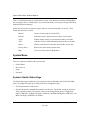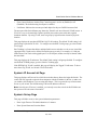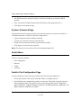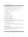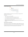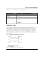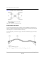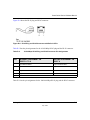
1
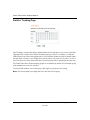
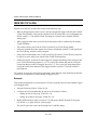
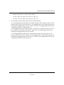
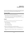
Smart Switch Series Software
Manual
NETGEAR, Inc.
4500 Great America Parkway
Santa Clara, CA 95054 USA
Phone 1-888-NETGEAR
July 2005
July 2005
© 2005 by NETGEAR, Inc. All rights reserved.
Trademarks
NETGEAR, Inc. NETGEAR, the Netgear logo, The Gear Guy and Everybody’s connecting are trademarks of Netgear,
Inc. in the United States and/or other countries. Other brand and product names are trademarks of their respective
holders. Information is subject to change without notice. All rights reserved.
Statement of Conditions
In the interest of improving internal design, operational function, and/or reliability, NETGEAR reserves the right to
make changes to the products described in this document without notice. NETGEAR does not assume any liability that
may occur due to the use or application of the product(s) or circuit layout(s) described herein.
Customer Support
For assistance with installing and configuring your NETGEAR system or with questions or problems following
installation:
•
Check the NETGEAR Web page at http://www.NETGEAR.com.
•
Call Technical Support in North America at 1-888-NETGEAR. If you are outside North America, please refer to
the phone numbers listed on the Support Information Card that shipped with your switch.
•
Email Technical Support at [email protected].
Defective or damaged merchandise can be returned to your point-of-purchase representative.
NETGEAR maintains a World Wide Web home page that you can access at the uniform resource locator (URL) http://
www.NETGEAR.com. A direct connection to the Internet and a Web browser such as Internet Explorer or Netscape are
required.
2
July 2005
Contents
Chapter 1
About This Guide
Audience .........................................................................................................................1-1
Why the Document was Created ....................................................................................1-1
How to Use This Document ............................................................................................1-1
Typographical Conventions ............................................................................................1-2
Special Message Formats ..............................................................................................1-2
Chapter 2
Switch Management Overview
Management Access Overview ......................................................................................1-1
.................................................................................................................................1-2
Chapter 3
Getting Started
For a Network with a DHCP Server ...............................................................................2-1
For a Network without a DHCP Server ..........................................................................2-3
Chapter 4
Web-Based Management Interface
System Menu ..................................................................................................................3-2
System> Switch Status Page ..................................................................................3-2
System> IP Access List Page .................................................................................3-3
System> Set-up Page .............................................................................................3-3
System> Password Page ........................................................................................3-4
Switch Menu ..................................................................................................................3-4
Switch> Port Configuration Page ............................................................................3-4
Switch> Port Configuration: Set speed ............................................................3-5
Switch> Port Configuration: Set flow control ....................................................3-5
Switch> Statistics Page ...........................................................................................3-5
Switch> Statistics> Refresh ..............................................................................3-6
Switch> Statistics> Clear Counter ....................................................................3-6
Switch> VLAN Page ................................................................................................3-6
Switch> VLAN> Port-based VLAN ...................................................................3-7
Contents
iii
July 2005
Switch> VLAN> IEEE802.1Q Tag VLAN ..........................................................3-7
Switch> Trunking Page ...........................................................................................3-9
Switch> Monitor Page ...........................................................................................3-10
Switch> Advanced> Jumbo Frame ..................................................................3-10
Switch> Advanced> Spanning Tree Page ....................................................... 3-11
Switch> Advanced> SNMP ............................................................................. 3-11
Firmware Menu ............................................................................................................3-12
Firmware> Configuration Backup Page ................................................................3-12
Firmware> Factory Reset Page ............................................................................3-12
Logout ..........................................................................................................................3-13
Chapter 5
Software Upgrade
Appendix A
Default Settings
Appendix B
IEEE 802.1Q Virtual Local Area Network (VLAN)
IEEE 802.1Q VLANs .................................................................................................... A-2
Appendix C
Port-Based VLAN
Port-based VLANs ........................................................................................................ A-1
Example ................................................................................................................. A-1
Scenarios: .............................................................................................................. A-2
Appendix D
Cabling Guidelines
Fast Ethernet Cable Guidelines ..................................................................................... B-1
Category 5 Cable ........................................................................................................... B-2
Category 5 Cable Specifications ............................................................................. B-2
Twisted Pair Cables ................................................................................................ B-3
Patch Panels and Cables ........................................................................................ B-4
Using 1000BASE-T Gigabit Ethernet over Category 5 Cable ....................................... B-5
Cabling .................................................................................................................... B-5
Near End Cross Talk (NEXT) .................................................................................. B-6
Patch Cables ........................................................................................................... B-6
RJ-45 Plug and RJ-45 Connectors ......................................................................... B-6
Conclusion .............................................................................................................. B-8
iv
Contents
July 2005
Chapter 1
About This Guide
Thank you for purchasing the NETGEAR™ Smart Switch Series Switch.
Audience
This reference manual assumes that the reader has basic-to-intermediate computer and Internet
skills. However, basic computer network, Internet, and wireless technology tutorial information is
provided in the Appendices.
This document describes configuration commands for the Smart Switch Series Switch software.
The commands can be accessed from the CLI, telnet, and Web interfaces.
Why the Document was Created
This document was created primarily for system administrators configuring and operating a
system using Smart Switch Series Switch software. It is intended to provide an understanding of
the configuration options of Smart Switch Series Switch software.
It is assumed that the reader has an understanding of the relevant switch platforms. It is also
assumed that the reader has a basic knowledge of Ethernet and networking concepts.
How to Use This Document
This document describes configuration commands for the Smart Switch Series Switch software.
The commands can be accessed from the CLI, telnet (CMI), and Web interfaces.
•
Chapter 4, “Administration Console Telnet Interface” describes the CMI.
•
Chapter 4, “Web-Based Management Interface” describes the Web interface.
•
Chapter 5, “Software Upgrade” describes the CLI, which can be reached through the telnet
(CMI) interface.
About This Guide
1-1
July 2005
Smart Switch Series Software Manual
Note: Refer to the release notes for the Smart Switch Series Switch Software application level
code. The release notes detail the platform specific functionality of the Switching, SNMP, Config,
and Management packages.
Typographical Conventions
This guide uses the following typographical conventions:
Table 1.
Typographical conventions
italics
Emphasis.
bold times roman
User input.
[Enter]
Named keys in text are shown enclosed in square brackets. The notation [Enter]
is used for the Enter key and the Return key.
[Ctrl]+C
Two or more keys that must be pressed simultaneously are shown in text linked
with a plus (+) sign.
SMALL CAPS
DOS file and directory names.
Special Message Formats
This guide uses the following formats to highlight special messages:
Note: This format is used to highlight information of importance or special interest.
This manual is written for the Smart Switch Series Switch according to these specifications:
Table 1-1.
Manual Specifications
Product Version
Smart Switch Series Switch
Manual Publication Date
July 2005
Note: Product updates are available on the NETGEAR, Inc. Web site
at http://www.netgear.com/support/main.asp.
1-2
About This Guide
July 2005
Chapter 2
Switch Management Overview
This chapter gives an overview of switch management, including the methods you can use to
manage your NETGEAR Smart Switch Series Switch. Topics include:
•
Management Access Overview
•
SNMP Access
•
Protocols
Management Access Overview
Your NETGEAR Smart Switch contains software for viewing, changing, and monitoring the way
it works. This management software is not required for the switch to work. You can use the 10/
100 Mbps ports and the built-in Gigabit ports without using the management software. However,
the management software allows you configure ports, VLAN and Trunking features and also
improve the efficiency of the switch and, as a result, improve the overall performance of your
network. The Switch gives you the flexibility to access and manage the switch using any of the
following methods:
•
Smartwizard Discovery Utility program
•
Web browser interface
After you power-up the switch for the first time, you can configure it using a utility program called
Smartwizard Discovery or a Web browser. Please refer to the screenshots in following pages for
Smartwizard Discovery Utility and Web Management GUI. Each of these management methods
has advantages. The table below compares the two management methods.
Switch Management Overview
2-1
July 2005
Smart Switch Series Software Manual
Table 2-1.
Comparing Switch Management Methods
Management Method
Advantages
Disadvantages
SmartWizard
Discovery Utility
• No IP address or subnet needed Show all • Not convenient for remote access
switches on the network
• User-friendly interface
• Firmware upgradeable
Web browser
• Can be accessed from any location via the • Security can be compromised (hackers
switch’s IP address
can attack if they know IP address)
• Password protected
• May encounter lag times on poor
• Ideal for configuring the switch remotely
connections
• Compatible with Internet Explorer and
• Displaying graphical objects over a
Netscape Navigator Web browsers
browser interface may slow navigation
• Intuitive browser interface
• Most visually appealing
• Extensive switch configuration allowed
• Configuration backup for duplicating
settings to other switches
SNMP Agent
• Communicates with switch functions at the • Requires SNMP manager software
Management Information Base (MIB) level • Least visually appealing of all three
• Based on open standards
methods
• Limited amount of information
available
• Some settings require calculations
• Security can be compromised (hackers
need only know the community name)
2-2
Switch Management Overview
July 2005
Smart Switch Series Software Manual
Switch Management Overview
2-3
July 2005
Chapter 3
Getting Started
This chapter will walk you through the steps to start managing your switch. This chapter will
cover how to get started in a network with a DHCP server (most common) as well as if you do not
have a DHCP server.
For a Network with a DHCP Server
1.
2.
3.
4.
5.
6.
Connect the Smart Switch to a DHCP network.
Power on the Smart Switch by plugging in power cord.
Install the Smartwizard Discovery program on your computer
Start the Smartwizard Discovery utility. (Chapter 4 has detailed instructions on the
Smartwizard Discovery utility)
Click Discover of the Smartwizard Discovery utility to find your switch. You should see a
something similar to Figure 2-1.
Select your switch by clicking on it. Then click on Web Access, as highlighted in Figure 2-2.
Figure 3-1: Smartwizard Discovery Utility > Discover
Getting Started
3-1
July 2005
Smart Switch Series Software Manual
Figure 3-2: Smartwizard Discovery > Web Access
7.
To manage your switch via your web browser, click Web Access. The main page below will
display. The default password is password.
Figure 3-3: Web Management main page
Getting Started
3-2
July 2005
Smart Switch Series Software Manual
For a Network without a DHCP Server
1.
Connect your switch to your existing network.
2.
Power on your switch by plugging in the power cord.
3.
The default IP is 192.168.0.239.
4.
Install the Smartwizard Discovery program on your PC.
5.
Start the Smartwizard Discovery utility.
6.
Click Discover to find your switch.
7.
Click Configuration Setting.
Figure 3-4: Assigning the switch a static IP address
8.
Choose Disable on DHCP.
9.
Enter your IP address, Gateway and Subnet. Then, type your password and click Set. Make
sure your PC and your switch are in the same subnet.
Note: You can always assign a Static IP address to your switch no matter if your network has a
DHCP server or not.
10. Select your switch by clicking on it. Then click Web Access.
3-3
Getting Started
July 2005
Smart Switch Series Software Manual
11. To manage your switch via your web browser, click Web Access. The main page below will
display. The default password is password.
Figure 3-5: Web Management main page
Getting Started
3-4
July 2005
Smart Switch Series Software Manual
3-5
Getting Started
July 2005
Chapter 4
Web-Based Management Interface
Your NETGEAR Smart Switch series provides a built-in browser interface that lets you configure
and manage it remotely using a standard Web browser such as Microsoft Internet Explorer or
Netscape Navigator. This interface also allows for system monitoring of the switch. The help page
will cover many of the basic functions and features of the switch and its web interface.
Web Management requires either Microsoft Internet Explorer 5.0 or later or Netscape Navigator
6.0 or later.
Note: Only one user can be logged in at any time.
There are 3 menu options available:
•
System
•
Switch
•
Firmware
Web-Based Management Interface
4-1
July 2005
Smart Switch Series Software Manual
There is a Help Menu in the top of right side of screen. Click the help to read the full Help Menu.
On some pages, there is a Help button. If you click that button, you will go to the part of the Help
Menu that discusses that page.
Within the various browser interface pages, there are several buttons that you can use. Their
names and functions are below:
Browse:
Locates a certain path for a desired file.
Refresh:
Pulls that screen’s data from current values on the system
Apply:
Submits change request to system and refreshes screen data
Add:
Add new entries to table information and refreshes screen data
Delete:
Deletes selected entries from table and refreshes screen data
Factory Reset:
Restore the system factory default value.
Help:
Goes to relevant section of Help Menu
System Menu
There are 4 options available in the system menu:
•
Switch Status
•
IP Access List
•
Setup
•
Password
System> Switch Status Page
The Switch Status page displays the port settings for both 10/100 Mbps and 10/100/1000 Mbps
ports. To configure the ports, go to the Switch> Port Configuration page.
•
ID: The port number on the switch
•
Speed: Indicates the communication mode set for the port. The default setting for all ports is
Auto-negotiation (Auto). The possible entries are Auto-negotiation (Auto), 10 Mbps half
duplex (10M Half), 10 Mbps full duplex (10M Full), 100 Mbps half duplex (100M Half), 100
Mbps full duplex (100M Full), or Disable.
4-2
Web-Based Management Interface
July 2005
Smart Switch Series Software Manual
•
Flow Control: Indicates whether Flow Control support is set for on (Enabled) or off
(Disabled). The default setting for all ports is enabled.
•
Link Status: Indicates the current speed and duplex for the port. DOWN means no link.
The next part of the Switch Status page shows the Virtual Local Area Network (VLAN) status. A
VLAN is a way to electronically separate specified ports on the same switch into separate
broadcast domains. By using VLAN, users can group by logical function instead of physical
location.
This page displays the port-based IEEE 802.1Q VLAN settings. The default VLAN setting is all
ports belong to port-based VLAN 1. To configure user-defined VLAN groups, go to the Switch>
VLAN page.
Port Trunking is a feature that allows multiple links between switches to work as one virtual link
(aggregate link). Trunks can be defined for similar port types only. For example, a 10/100 port
cannot form a Port Trunk with a gigabit port. For 10/100 ports, trunks can only be formed within
the same bank.
This page displays the Trunk status. The default Trunk setting is all groups disabled. To configure
user-defined TURNK groups, go to the Switch> Trunking page.
If the IEEE802.1Q VLAN is enabled, this page will display the Tagged VLAN status. To know
more about Tag VLAN, see Switch> VLAN for details.
System> IP Access List Page
This page displays an IP access list, which lists switches that are allowed to login this Switch. The
switch will only respond to requests from computers with the IP address in the list, so make sure
you include your IP address if you are using this feature. This is a powerful way to limit remote
access to your switch. The default setting is all host IP addresses allowed.
Note: Once this new IP access is enabled, you can only access the switch via this IP. Make sure
that your new IP is the same of current PC.
System> Set-up Page
This page will allow access to the system information parameters.
•
Enter Login Timeout. The default duration is 5 minutes.
•
Enter System Name and Location Name
Web-Based Management Interface
4-3
July 2005
Smart Switch Series Software Manual
•
The DHCP function is enabled by default. Click Static IP Address to disable the DHCP
function.
•
Enter site-specific IP address, Subnet mask and Gateway in the appropriate boxes
•
Click Apply to activate the setting
System> Password Page
The password entered is encrypted on the screen and will display as a sequence of asterisks (*).
The default password is ‘password’ and can be changed here.
•
Type the old password in the Old Password field
•
Type the new password in the New Password field
•
Re-type the new password in the Re-type New Password field
•
Click Apply to activate the new password
Note: The password is case sensitive and with a maximum length of 20.
Switch Menu
There are 4 options available:
•
Port Configuration
•
Statistics
•
VLAN
•
Trunking
Switch> Port Configuration Page
You can configure the status per port by clicking a port ID at the port setting menu.
•
ID: The port number on the switch. Click this number to configure the port.
•
Speed: Indicates the communication mode set for the port. The default setting for all ports is
Auto-negotiation (Auto). The possible entries are Auto-negotiation (Auto), 10 Mbps half
duplex (10M Half), 10 Mbps full duplex (10M Full), 100 Mbps half duplex (100M Half), 100
Mbps full duplex (100M Full), or Disable.
4-4
Web-Based Management Interface
July 2005
Smart Switch Series Software Manual
•
Flow Control: Indicates whether Flow Control support is set for on (Enabled) or off
(Disabled). The default setting for all ports is enabled.
•
Link Status: Indicates the current speed and duplex for the port. DOWN means no link.
Switch> Port Configuration: Set speed
•
Click a port ID.
•
Click to select a speed from the pull-down menu under Speed.
•
Click Apply to activate the new speed.
Note: Please be aware that speed must set as same as link partner. Otherwise, packet loss or link
error might occur.
Switch> Port Configuration: Set flow control
•
Click a port ID.
•
Click to select Enable or Disable from the pull-down menu under Flow Control.
•
Click Apply to activate the new setting.
Switch> Statistics Page
The Statistics Table shows the statistics types for one port over time.
•
ID: The port number on the switch
•
Tx: Transmitted packet/s.
•
Rx: Received packet/s.
Web-Based Management Interface
4-5
July 2005
Smart Switch Series Software Manual
•
Tx Error: Transmitted packet/s with error.
•
Rx Error: Received packet/s with error. Packets are counted as TX Error if they:
•
Had a late collision detected during the transmission (512 bit-times into the transmission).
•
Experienced 16 failed transmission attempts due to collision.
•
Were dropped due to lack of resources. Packets are counted as RX Error if they:
•
Were less than 64 bytes or greater than 1522 bytes?
•
Had a bad FCS.
•
Were dropped due to lack of resources.
Switch> Statistics> Refresh
Click Refresh to obtain current statistics data.
Switch> Statistics> Clear Counter
Click Clear Counter to start new statistics over time.
Switch> Statistics>Q0S Page
Indicate the priority for the port. Quality of Service (QoS) is a way of managing traffic in a
network, by treating different types of traffic with different levels of priority. Higher priority traffic
gets faster treatment during times of switch congestion.
The QoS page supports two types of QoS:
•
Port-based QoS is the defualt option and the default setting for all ports is normal.
•
IEEE802.1p-based QoS allows user to map different IEEE801.1p traffic to different levels of
priority.
Switch> VLAN Page
A Virtual Local Area Network (VLAN) is a means to electronically separate ports on the same
switch from a single broadcast domain into separate broadcast domains. By using VLAN, users
can group by logical function instead of physical location.
The VLAN Table shows two types of VLAN and other information:
4-6
Web-Based Management Interface
July 2005
Smart Switch Series Software Manual
•
IEEE 802.1Q VLAN (Tagged VLAN)
•
Port-based VLAN
•
ID: The port number on the switch
•
Description: User-definable
•
Member: Indicates which port/s belong to a VLAN group
Switch> VLAN> Port-based VLAN
Multiple port-based VLAN groups are supported on the switch, and any one port can belong to
different VLAN groups. The number of supported port-based VLAN groups varies according to
the switch model.
The default VLAN group port-based VLAN that have all ports belonging to VLAN 1.
Change members
•
Click a VLAN ID
•
Click to select port/s for VLAN members
•
Click Apply to activate the new setting
Add VLAN
•
Click Add VLAN.
•
Enter a description for this VLAN
•
Click to select port/s for VLAN members or click Set all to select all ports
•
Click Clear all to unselect all ports
•
Click Apply to activate the new setting
Delete VLAN
•
Click Delete VLAN
•
Click to select a VLAN ID
•
Click Apply to confirm delete this VLAN
Web-Based Management Interface
4-7
July 2005
Smart Switch Series Software Manual
Switch> VLAN> IEEE802.1Q Tag VLAN
Depending on your model switch there are up to 64 static Tag VLAN groups supported on your
switch. The VLAN tagging option is a standard set by the IEEE to facilitate the spanning of
VLANs across multiple switches (Reference: Appendix A and IEEE Std 802.1Q-1998 Virtual
Bridged Local Area Networks).
Click to select IEEE802.1Q VLAN. A screen pops up to confirm this change.
All ports are set belonging to VLAN 1 by default, all untagged.
From the page, you can create a new VLAN, add new ports to an existing VLAN, remove ports
from an existing VLAN or, delete a VLAN.
Add a port to a VLAN Group
•
Under the VLAN ID drop down menu, select the VLAN you want to edit.
•
Click the box below the port number so that a ‘T’ (tagged) or ‘U’ (untagged) appears.
•
Click Apply.
Remove a port from a VLAN Group
•
Click the box again until a blank box appears. This will remove VLAN membership from the
port.
•
Click Apply.
Note: The default PVID of all ports is 1; therefore, you cannot remove any ports for the default
Tag VLAN. It means that before removing any desired port from default Tag VLAN, changes
PVID of such desired port to the PVID other than 1.
Create a new VLAN Group
•
Under the VLAN ID drop down menu, select Add new VLAN.
•
Enter the VLAN ID “2” in the provided fields. VLAN ID must be set within 2 ~ 4094.
•
Add VLAN members if so desired; click the box below the port number so that a ‘T’ (tagged)
or ‘U’ (untagged) appears.
•
Click Apply.
4-8
Web-Based Management Interface
July 2005
Smart Switch Series Software Manual
Note: To allow untagged packets to participate in VLAN 2, make sure to change the Port VLAN
Ids (PVID) for the relevant ports. Access the PVID Settings by using the VLAN ID drop down
menu.
Delete a VLAN Group
•
Under the VLAN ID drop down menu, select the VLAN you want to remove.
•
Click to select Remove VLAN.
•
Click Apply.
PVID Setting
All untagged packets entering the switch will by default be tagged with the port’s Primary VLAN
Identification (PVID). This screen allows you to specify the PVID for each port.
Take VLAN 2 for example: ports 5, 6, 7, and 8 have been checked as tagged ports for this VLAN.
You must change the PVID value from “1” to “2” for those ports to avoid losing untagged packets
when they are received.
Under the VLAN ID drop down menu, select PVID Setting. See below for an example of setting
PVID for VLAN 2.
Change the PVID value of ports 5, 6, 7, and 8.
Click Apply.
Web-Based Management Interface
4-9
July 2005
Smart Switch Series Software Manual
Switch> Trunking Page
Port Trunking is a feature that allows multiple links between switches to work as one virtual link
(aggregate link). Trunks can be defined for similar port types only. For example, a 10/100 port
cannot form a Port Trunk with a gigabit port. For 10/100 ports, trunks can only be formed within
the same bank. A bank is a set of eight ports, such as ports 1 to 8, ports 9 to 16, ports 17 to 24, or
port 25 and port 26, on the same switch unit. Up to four trunks can be operating at the same time.
The Trunk Table shows all four trunking groups are set disabled by default. For each trunk group,
trunk members are pre-set for selection.
To select Trunk members for a Trunk group, click Apply to activate the new setting
Note: The selected trunk port setting must set to the same VLAN group.
4-10
Web-Based Management Interface
July 2005
Smart Switch Series Software Manual
Switch> Monitor Page
The Monitor feature allows you to configure any port's incoming and/or outgoing traffic to be
mirrored to a pre-defined sniffer port.
Sniffer Mode:
•
.Disable - disable port mirroring globally.
•
.RX - mirroring only the ingress traffic to the designated source ports.
•
.TX - mirroring only the egress traffic to the designated source ports.
•
Both - mirroring both incoming and outgoing traffic on the designated source ports.
•
Sniffer Port: Select one from a pull-down menu.
•
Source Ports: Select any number of ports to be monitored (mirrored). The ports can not be the
Sniffer port
Switch> Advanced> Jumbo Frame
This page allows you to enable or disable the Jumbo Frame support. Jumbo Frames are not an
approved standard Ethernet frame size, so you will need to ensure that all of your networking gear
can support these non-standard Jumbo Frames to prevent them from being dropped. By clicking
'Help' button on this page, you can see the maximum frame size the switch can carry.
Web-Based Management Interface
4-11
July 2005
Smart Switch Series Software Manual
Switch> Advanced> Spanning Tree Page
•
Fast Link: When a port running the standard Spanning Tree Protocol (STP) is connected, it
will go through the STP negotiation ( listening -> learning -> forwarding or blocking ) before
it will be fully available. If a server is trying to access a client through the switch running the
STP negotiation, it will not be able to connect to it immediately. This can be a problem for
some networks. Fastlink mode solves this problem by setting the port directly to forwarding
mode, thus allowing any server access request to be forwarded. Fastlink mode can cause
temporary loops in your network, but the STP will eliminate them. Fastlink is best used on end
node ports, i.e. ports connected to PCs or servers, to avoid network loops.
•
Bridge Priority: Priority setting of this switch in the Spanning Tree.
•
Bridge Max Age: Amount of time before a configuration message is discarded by the system.
•
Bridge Hello Time: Interval between configuration messages sent by the Spanning Tree
algorithm.
•
Bridge Forward Delay: Amount of time system spends in 'learning' and 'listening' states.
•
Path Cost: The switch uses this to determine which port is the forwarding port. All other
factors equal, the path with the lowest cost to the root bridge will be the active path.
•
Path Priority: STP bases on this to determine the port to use for forwarding. The port with the
lowest number has the highest priority.
Switch> Advanced> SNMP
SNMP page allows you to limit the IP address which can access the MIB of the switch and which
the switch will send trap to. The switch will only respond to requests from computers with the IP
address in the list. You can also select the traps which the switch will send to the hosts in the
following trap events. The setting of a host will not be active until it is set to “Enable” in the
Admin field.
Trap Events :
•
Device bootup - The switch generates an SNMP trap when it reboots.
•
Authentication fail - The switch generates an SNMP trap when a host tries to gain access to the
switch but the host's IP is not in the SNMP host table.
•
Link Up/Down - The switch generates an SNMP trap when one of its ports changes its link
status.
4-12
Web-Based Management Interface
July 2005
Smart Switch Series Software Manual
Firmware Menu
There are 2 options available:
•
Configuration Backup
•
Factory Reset
Firmware> Configuration Backup Page
You can backup the system and switch settings to your workstation. This can help you to
reconfigure the switch quickly if you have to re-set to factory defaults. Additionally, if you want
to try out different configurations on the switch, this feature will enable you to quickly return to a
previous configuration.
If you own several switches and you want them to have the same configuration, you can use this
feature to duplicate the settings to each switch.
Saving your Backup file:
•
Click Backup to store the current setting to a file in your PC.
•
Follow the instructions on the screen to select where you want to store your Backup file.
Restoring your Backup file (or using a duplicate configuration):
•
Click Restore to recover the Backup file from your PC to the current switch. If you do not
want to type in the path name, click Browse to find the Backup file.
•
Click OK in the File Download dialog box.
•
When download process is finished, click OK to confirm disconnection of current browser
connection.
Note: Please be aware that the switch will reboot after a successful restore.
Note: The Backup file does not affect the password and MAC address of the switch
Firmware> Factory Reset Page
You can always reset the switch to default values by using this function.
•
Click Factory Reset to enable this function
•
When reset process is finished, click OK to confirm disconnection of current browser
connection as shown in Figure 5-34.
Web-Based Management Interface
4-13
July 2005
Smart Switch Series Software Manual
Note: Please be aware that the switch will reboot after a successful reset.
Logout
When finished with all configuration and settings, click Logout to disconnect the current browser
connection. The login page will pop up.
4-14
Web-Based Management Interface
July 2005
Chapter 5
Software Upgrade
The application software for the Smart Switch is upgradeable, enabling your switch to take
advantage of improvements and additional features as they become available. The upgrade
procedure and the required equipment are described in the following section. The upgrade
procedure is as follows:
1.
Save the new firmware to your computer.
2.
Start the Smartwizard Discovery utility program.
3.
Select your switch by clicking on it.
4.
Then click Firmware Upgrade.
5.
Enter the location of the new firmware in the Firmware path below Firmware setting.
Alternatively, you can click Browse to locate the file.
6.
Click Start to download the new firmware file in non-volatile memory.
Note: Once the system finishes firmware upgrade process, the switch will automatically reboot.
The Smartwizard Discovery utility will determine success of upgrade process based on the success
of the system reboot.
Software Upgrade
5-1
July 2005
Smart Switch Series Software Manual
5-2
Software Upgrade
July 2005
Appendix B
IEEE 802.1Q Virtual Local Area Network (VLAN)
A Local Area Network (LAN) can generally be defined as a broadcast domain. Hubs, bridges or
switches in the same physical segment or segments connect all end node devices. End nodes can
communicate with each other without the need for a router. Routers connect LANs together,
routing the traffic to appropriate port.
A virtual LAN (VLAN) is a local-area network with a definition that maps workstations on some
other basis than geographic location (for example, by department, type of user, or primary
application). To communicate between VLANs, traffic must go through a router, just as if they
were on two separate LANs.
A VLAN is a group of PCs, servers and other network resources that behave as if they were
connected to a single, network segment — even though they may not be. For example, all
marketing personnel may be spread throughout a building. Yet if they are all assigned to a single
VLAN, they can share resources and bandwidth as if they were connected to the same segment.
The resources of other departments can be invisible to the marketing VLAN members, accessible
to all, or accessible only to specified individuals, depending on how the IT manager has set up the
VLANs.
The Advantages of VLANs
Easy to do network segmentation
Users communicate most frequently with each other can be grouped into common VLANs,
regardless of physical location. Each group's traffic is largely contained within the VLAN,
reducing extraneous traffic and improving the efficiency of the whole network.
Easy to manage
The addition of nodes, as well as moves and other changes, can be dealt with quickly and
conveniently from a management interface rather than the wiring closet.
Increased performance
VLANs free up bandwidth by limiting node-to-node and broadcast traffic throughout the network.
Enhanced network security
VLANs create virtual boundaries that can only be crossed through a router. So standard,
router-based security measures can be used to restrict access to each VLAN
IEEE 802.1Q Virtual Local Area Network (VLAN)
July 2005
B-1
Smart Switch Series Software Manual
IEEE 802.1Q VLANs
Packets received by the switch will be treated in the following way:
•
When an untagged packet enters a port, it will be automatically tagged with the port’s default
VLAN ID tag number. Each port has a default VLAN ID setting that is user configurable (the
default setting is 1). The default VLAN ID setting for each port can be changed in PVID
Setting page.
•
When a tagged packet enters a port, the tag for that packet will be unaffected by the default
VLAN ID Setting.
•
The packet will now proceed to the VLAN specified by its VLAN ID tag number.
•
If the port in which the packet entered does not have membership with the VLAN specified by
the VLAN ID tag, the packet will be dropped.
•
If the port has membership to the VLAN specified by the packet’s VLAN ID, the packet will
be able to be sent to other ports with the same VLAN ID membership.
•
Packets leaving the switch will be either tagged or untagged depending on the setting for that
port’s VLAN membership properties. A ‘U’ for a given port means that packets leaving the
switch from that port will be Untagged. Inversely, a ‘T’ for a given port means that packets
leaving the switch from that port will be tagged with the respective VLAN ID in which it
participated in.
The example given in this section will step through a more elaborate setup illustrating all possible
scenarios for a comprehensive understanding of tagged VLANs.
Example
This example demonstrates several scenarios of VLAN use and how the switch will handle Tagged
and Untagged traffic.
1.
Setup the following VLANs: VLAN 10, 20.
2.
Configure the VLAN membership. Be sure to set all of them as follows.
3.
•
Setting up first VLAN group, VLAN ID = 10:
•
Setting up second VLAN group, VLAN ID = 20:
Modify PVID Setting to apply previous two VLAN groups: Modify Default VLAN group
(VLAN ID = 1) to apply two new VLAN groups:
The specific ports above have the following Port VLAN ID settings:
B-2
IEEE 802.1Q Virtual Local Area Network (VLAN)
July 2005
Smart Switch Series Software Manual
4.
•
Default VLAN: Port 7 – Port 26 (all U), VID = 1
•
VLAN 1: Port 1 (U), Port 2 (U), Port 3 (T), VID = 10
•
VLAN 2: Port 4 (U), Port 5 (T), Port 6 (U), VID = 20.
The following scenarios will produce results as described below:
(1). If an untagged packet enters Port 1, the switch will tag it with a VLAN tag value 10. The
packet will have access to Port 2 and Port 3. The outgoing packet will be stripped away its tag
becoming an untagged packet as it leaves Port 2. For Port 3, the outgoing packet will leave as
a tagged packet with a VLAN tag value 10.
(2). If a tagged packet with a VLAN tag value 10 enters Port 3, the packet will have access to
Port 1 and Port 2. If the packet leaves Port 1 and/or Port 2, it will be stripped away its tag
becoming an untagged packet as it leaves switch.
(3). If an untagged packet enters Port 4, switch will tag it with a VLAN tag value 20. The
packet will have access to Port 5 and Port 6. The outgoing packet will be stripped away its tag
becoming an untagged packet as it leaves Port 6. For Port 5, the outgoing packet will leave as
a tagged packet with a VLAN tag value 20.
IEEE 802.1Q Virtual Local Area Network (VLAN)
July 2005
B-3
Smart Switch Series Software Manual
B-4
IEEE 802.1Q Virtual Local Area Network (VLAN)
July 2005
Appendix C
Port-Based VLAN
Port-based VLAN will help efficiently confine the broadcast traffic to the switch ports. This switch
allows up to 26 port-based VLAN groups, any one port can belong to different VLAN groups. The
default VLAN group port-based VLAN that have all ports belonging to VLAN 1.
Port-based VLANs
Packets received by the switch will be treated in the following way:
•
When a packet enters a port, it only can proceed to the VLAN which the port belongs to. The
packet will be able to be sent to other ports with the same VLAN ID membership.
•
If the port in which the packet entered does not have membership with the same VLAN as the
source port does, the packet will be dropped.
Example
This example basically demonstrates how the port-based VLANs work to meet your needs.
Setup the following VLANs, each with defined descriptions:
•
VLAN 1 (IT department)
•
VLAN 2 (Sales department)
•
VLAN 3 (Marketing department)
•
VLAN 4 (Accounting department).
Configure the VLAN membership. Be sure to set all of them as follows.
•
Setting up second VLAN group (Sales), VLAN ID = 02, with membership of ports 1~8, 25.
•
Setting up third VLAN group (Marketing), VLAN ID = 03, with membership of ports 7~14,
25.
•
Setting up fourth VLAN group (Accounting), VLAN ID = 04, with membership of ports
19~20, 25.
Port-Based VLAN
C-1
July 2005
Smart Switch Series Software Manual
•
Setting up first VLAN group (IT), VLAN ID = 01, with membership of all ports.
Since VLAN ID 01 has been setup by default, you will have to remove the ports that belong to
all other VLAN group except port 25.
•
Ports 7 and 8 are kept for the usage of connecting file server and printer server. Sales and
Marketing departments can share file archives and printing services.
•
Port 25 provides Gigabit speed for email server and Internet connection.
The specific ports above have the following functions:
•
VLAN 1: Port 15 – Port 18, Port 21 – Port 24, Port 26, for IT department to monitor and
control activities on all other VLANs
•
VLAN 2: Port 1 – Port 8, for Sales department, port 7 and 8 connect to file archives and printer
server.
•
VLAN 3: Port 7 – Port 14, for Marketing department, port 7 and 8 connect to file archives and
printer server.
•
VLAN 4: Port 19 – Port 20, for Accounting department, its work is kept secret from other
departments except IT.
Scenarios:
If a packet comes in on port 2, it can go to ports 1, 3, 4, 5, 6, 7, 8, and 25, as those are the only ports
in that VLAN. A Sales person on Port 2 can get to the Internet, send and receive email, but cannot
access the marketing department print server or file archives.
If a Marketing user sends out a broadcast message, the Sales and Accounting departments will not
be affected by the message, as it will not go out on their ports. Only the Marketing department and
the IT group will get the broadcast message.
If an IT user sends out a broadcast message, everyone will get it.
C-2
Port-Based VLAN
July 2005
Appendix D
Cabling Guidelines
This appendix provides specifications for cables used with a NETGEAR Smart Switch Series
Switch.
Fast Ethernet Cable Guidelines
Fast Ethernet uses UTP cable, as specified in the IEEE 802.3u standard for 100BASE-TX.The
specification requires Category 5 UTP cable consisting of either two-pair or four-pair twisted
insulated copper conductors bound in a single plastic sheath. Category 5 cable is certified up to
100 MHz bandwidth. 100BASE-TX operation uses one pair of wires for transmission and the
other pair for receiving and for collision detection.
When installing Category 5 UTP cabling, use the following guidelines to ensure that your cables
perform to the following specifications:
Certification
Make sure that your Category 5 UTP cable has completed the Underwriters’ Laboratories (UL) or
Electronic Testing Laboratories (ETL) certification process.
Termination method
To minimize cross-talk noise, maintain the twist ratio of the cable up to the point of termination;
untwist at any RJ-45 plug or patch panel should not exceed 0.5 inch (1.5 cm).
Cabling Guidelines
D-1
July 2005
Smart Switch Series Software Manual
Category 5 Cable
Category 5 distributed cable that meets ANSI/EIA/TIA-568-A building wiring standards can be a
maximum of 328 feet (ft.) or 100 meters (m) in length, divided as follows:
20 ft. (6 m) between the hub and the patch panel (if used)
295 ft. (90 m) from the wiring closet to the wall outlet
10 ft. (3 m) from the wall outlet to the desktop device
The patch panel and other connecting hardware must meet the requirements for 100 Mbps
operation (Category 5). Only 0.5 inch (1.5 cm) of untwist in the wire pair is allowed at any
termination point.
Category 5 Cable Specifications
Ensure that the fiber cable is crossed over to guarantee link.
Table F-1 lists the electrical requirements of Category 5 UTP cable.
D-2
Cabling Guidelines
July 2005
Smart Switch Series Software Manual
Table-D-1.
Electrical Requirements of Category 5 Cable
SPECIFICATIONS
CATEGORY 5 CABLE REQUIREMENTS
Number of pairs
Four
Impedance
100 ± 15%
Mutual capacitance at 1 KHz
5.6 nF per 100 m
Maximum attenuation
(dB per 100 m, at 20° C)
at 4 MHz: 8.2
at 31 MHz: 11.7
at 100 MHz: 22.0
NEXT loss (dB minimum)
at 16 MHz: 44
at 31 MHz: 39
at 100 MHz: 32
Twisted Pair Cables
For two devices to communicate, the transmitter of each device must be connected to the receiver
of the other device. The crossover function is usually implemented internally as part of the
circuitry in the device. Computers and workstation adapter cards are usually media-dependent
interface ports, called MDI or uplink ports. Most repeaters and switch ports are configured as
media-dependent interfaces with built-in crossover ports, called MDI-X or normal ports. Auto
Uplink technology automatically senses which connection, MDI or MDI-X, is needed and makes
the right connection.
Figure D-1 illustrates straight-through twisted pair cable.
Figure D-1: Straight-Through Twisted-Pair Cable
Cabling Guidelines
D-3
July 2005
Smart Switch Series Software Manual
Figure D-2 illustrates crossover twisted pair cable.
Figure D-2: Crossover Twisted-Pair Cable
Patch Panels and Cables
If you are using patch panels, make sure that they meet the 100BASE-TX requirements. Use
Category 5 UTP cable for all patch cables and work area cables to ensure that your UTP patch
cable rating meets or exceeds the distribution cable rating.
To wire patch panels, you need two Category 5 UTP cables with an RJ-45 plug at each end, as
shown here.
Figure D-3: Category 5 UTP Cable with Male RJ-45 Plug at Each End
D-4
Cabling Guidelines
July 2005
Smart Switch Series Software Manual
Note: Flat “silver satin” telephone cable may have the same RJ-45 plug. However, using telephone
cable results in excessive collisions, causing the attached port to be partitioned or disconnected
from the network.
Using 1000BASE-T Gigabit Ethernet over Category 5 Cable
When using the new 1000BASE-T standard, the limitations of cable installations and the steps
necessary to ensure optimum performance must be considered. The most important components in
your cabling system are patch panel connections, twists of the pairs at connector transition points,
the jacket around the twisted-pair cable, bundling of multiple pairs on horizontal runs and punch
down blocks. All of these factors affect the performance of 1000BASE-T technology if not
correctly implemented. The following sections are designed to act as a guide to correct cabling for
1000BASE-T.
Cabling
The 1000BASE-T product is designed to operate over Category 5 cabling. To further enhance the
operation, the cabling standards have been amended. The latest standard is Category 5e, which
defines a higher level of link performance than is available with Category 5 cable.
If installing new cable, we recommend using Category 5e cable, since it costs about the same as
Category 5 cable. If using the existing cable, be sure to have the cable plant tested by a
professional who can verify that it meets or exceeds either ANSI/EIA/TIA-568-A:1995 or ISO/
IEC 11801:1995 Category 5 specifications.
Length
The maximum distance limitation between two pieces of equipment is 100 m, as per the original
Ethernet specification. The end-to-end link is called the “channel.”
TSB-67 defines the “Basic Link” which is the portion of the link that is part of the building
infrastructure. This excludes patch and equipment cords. The maximum basic link length is 295
feet (90 m).
Return Loss
Return loss measures the amount of reflected signal energy resulting from impedance changes in
the cabling link. The nature of 1000BASE-T renders this measurement very important; if too much
energy is reflected back on to the receiver, the device does not perform optimally.
Cabling Guidelines
D-5
July 2005
Smart Switch Series Software Manual
Unlike 10BASE-T and 100BASE-TX, which use only two of the four pairs of wires within the
Category 5, 1000BASE-T uses all four pairs of the twisted pair. Make sure all wires are tested ⎯
this is important.
Factors that affect the return loss are:
The number of transition points, as there is a connection via an RJ-45 to another connector, a patch
panel, or device at each transition point.
Removing the jacket that surrounds the four pairs of twisted cable. It is highly recommended that,
when RJ-45 connections are made, this is minimized to 1-1/4 inch (32 mm).
Untwisting any pair of the twisted-pair cabling. It is important that any untwisting be minimized to
3/8 inch (10 mm) for RJ-45 connections.
Cabling or bundling of multiple Category 5 cables. This is regulated by ANSI/EIA/TIA-568A-3. If
not correctly implemented, this can adversely affect all cabling parameters.
Near End Cross Talk (NEXT)
This is a measure of the signal coupling from one wire to another, within a cable assembly, or
among cables within a bundle. NEXT measures the amount of cross-talk disturbance energy that is
detected at the near end of the link — the end where the transmitter is located. NEXT measures the
amount of energy that is “returned” to the sender end. The factors that affect NEXT and cross talk
are exactly the same as outlined in the Return Loss section. The cross-talk performance is directly
related to the quality of the cable installation.
Patch Cables
When installing your equipment, replace old patch panel cables that do not meet Category 5e
specifications. As pointed out in the NEXT section, this near end piece of cable is critical for
successful operation.
RJ-45 Plug and RJ-45 Connectors
In a Fast Ethernet network, it is important that all 100BASE-T certified Category 5 cabling use
RJ-45 plugs. The RJ-45 plug accepts 4-pair UTP or shielded twisted-pair (STP) 100-ohm cable
and connects into the RJ-45 connector. The RJ-45 connector is used to connect stations, hubs, and
switches through UTP cable; it supports 10 Mbps, 100 Mbps, or 1000 Mbps data transmission.
D-6
Cabling Guidelines
July 2005
Smart Switch Series Software Manual
Figure D-4 shows the RJ-45 plug and RJ-45 connector.
Figure D-4: RJ-45 Plug and RJ-45 Connector with Built-in LEDs
Table D-2 lists the pin assignments for the 10/100 Mbps RJ-45 plug and the RJ-45 connector.
Table-D-2.
10/100 Mbps RJ-45 Plug and RJ-45 Connector Pin Assignments
PIN
NORMAL ASSIGNMENT ON
PORTS 1 TO 8
UPLINK ASSIGNMENT ON
PORT 8
1
Input Receive Data +
Output Transmit Data +
2
Input Receive Data –
Output Transmit Data –
3
Output Transmit Data +
Input Receive Data +
6
Output Transmit Data –
Input Receive Data –
4, 5, 7, 8 Internal termination, not used for data transmission
Table E-2 lists the pin assignments for the 100/1000 Mbps RJ-45 plug and the RJ-45 connector.
Cabling Guidelines
D-7
July 2005
Smart Switch Series Software Manual
Table-D-3.
100/1000 Mbps RJ-45 Plug and RJ-45 Connector Pin Assignments
PIN
CHANNEL
DESCRIPTION
1
2
A
Rx/Tx Data +
Rx/Tx Data
3
6
B
Rx/Tx Data +
Rx/Tx Data
4
5
C
Rx/Tx Data +
Rx/Tx Data
7
8
D
Rx/Tx Data +
Rx/Tx Data
Conclusion
For optimum performance of your 1000BASE-T product, it is important to fully qualify your cable
installation and ensure it meets or exceeds ANSI/EIA/TIA-568-A:1995 or ISO/IEC 11801:1995
Category 5 specifications. Install Category 5e cable where possible, including patch panel cables.
Minimize transition points, jacket removal, and untwist lengths. Bundling of cables must be
properly installed to meet the requirements in ANSI/EIA/TIA-568A-3.
D-8
Cabling Guidelines
July 2005
Appendix A
Default Settings
This appendix provides default settings for the NETGEAR Smart Switches. You can always
configure the switch to default settings by using the Factory Reset function from a Web browser.
Table A-1.
Default Settings
FEATURE
DEFAULT SETTING
Port Speed
Auto-negotiation
Port Duplex
Auto-negotiation
Flow Control (half duplex)
Enabled
Flow Control (full duplex)
Enabled
IP Configuration
DHCP enabled
Password
password
VLAN
Port-Based VLAN
Link Aggregation (Trunk)
Disabled
Traffic Prioritization (QoS)
Optimized for flow control, all ports set normal priority
Default Settings
A-1
July 2005
Smart Switch Series Software Manual
A-2
Default Settings
July 2005
Index
Numerics
802.1x Port-Based Authentication 3-16, 4-25
CLI Configure Interface Duplex 5-16
CLI Configure Interface Help 5-17
CLI Configure Interface Mirror 5-17
A
Address Aging 3-26
Admin field 3-9
Advanced Security 3-16, 4-20, 4-25
Advanced Tools 4-21
Advanced> Spanning Tree 4-35
Advanced Options 4-19
Advantages of VLANs A-1
Auto MDI/MDI-X D-2
Auto Uplink D-2
B
CLI Configure Interface Negotiation 5-17
CLI Configure Interface No 5-18
CLI Configure Interface Shutdown 5-18
CLI Configure Interface Spanning Tree 5-19
CLI Configure Interface Speed 5-19
CLI Configure Interface Switchport 5-19
CLI Configure Interface Trunking 5-20
CLI Configure Interface Type 5-18
CLI Configure Location 5-24
CLI Configure mac-address-table 5-21
CLI Configure Max-Age 5-26
CLI Configure Multicast-Static 5-22
CLI Configure Multimedia 5-22
Bridge Priority 3-24
CLI Configure Name 5-24
Broadcast Control 3-21, 4-21
CLI Configure No 5-23
CLI Configure Priority 5-27
C
CLI Configure SNMP Server 5-23
Cat5 cable D-2
CLI Configure Spanning Tree 5-26
Class of Service 4-21
CLI Configure Static 5-21
CLI Configure 5-13
CLI Configure System 5-27
CLI Configure Aging-Timer 5-21
CLI Configure System Config-TFTP 5-27
CLI Configure Community 5-23
CLI Configure System config-tftp ip 5-27
CLI Configure Contact 5-24
CLI Configure System Config-tftp Path/File 5-28
CLI Configure DiffServ 5-13
CLI Configure System Firmware boot 5-31
CLI Configure Disable 5-22
CLI Configure System Firmware TFTP-File 5-32
CLI Configure Exit 5-15
CLI Configure System Firmware TFTP-IP 5-32
CLI Configure Forward Time 5-26
CLI Configure System Gateway 5-29
CLI Configure Hello Time 5-26
CLI Configure System IP 5-28
CLI Configure Host 5-25
CLI Configure System IP-Filter 5-28
CLI Configure Host Authorization 5-25
CLI Configure System IP-filter address 5-29
CLI Configure HPO 5-23
CLI Configure System IP-Mode 5-29
CLI Configure IGMP 5-23
CLI Configure System Mask 5-29
CLI Configure Interface 5-15
CLI Configure System Password 5-31
CLI Configure Interface CoS (Class or Service) 5-16
CLI Configure System RADIUS 5-32
CLI Configure Interface Description 5-16
CLI Configure System Reset 5-33
Index
1
CLI Configure System Restore 5-30
CLI Configure System Save 5-30
CLI Configure System Stat-Reset 5-34
CLI Configure System Username 5-31
CLI Configure System Web 5-30
CLI Configure Trap 5-25
CLI Exit 5-3
CLI Help 5-2
CLI Manual Syntax 5-1
D
Device Reset 4-18
Differentiated Service 3-20
Differentiated Service Code Points 3-20
DiffServ 3-20
Direct Console Access 3-1
Disable Advanced Alerting 4-20, 4-22
Documentation updates 1-2
DSCP 3-20
CLI Ping 5-2
CLI Show 5-3
CLI Show DiffServ 5-4
CLI Show Interfaces 5-4
CLI Show IP 5-5
CLI Show MAC Aging Time 5-6
CLI Show MAC Multicast-Static 5-6
CLI Show MAC Static 5-6
CLI Show Mac-Address-Table 5-5
CLI Show Mirror 5-7
E
Enable/Disable IGMP 3-27
Entering the CLI 5-1
Ethernet Oversize Packet Rate 4-6
Ethernet Oversize Packets 4-6
Ethernet Undersize Packet Rate 4-6
Ethernet Undersize Packets 4-6
CLI Show Multimedia 5-7
F
CLI Show Running-Config 5-7
Fastlink 3-25
CLI Show SNMP 5-8
Fastlink in STP mode 3-25, 4-37
CLI Show Spanning-Tree Brief 5-9
Flow Control 3-10
CLI Show Spanning-Tree Interface 5-10
Forward Delay 3-24, 4-36
CLI Show System 5-10
CLI Show Trunking 5-11
G
CLI Show VLAN 5-11, 5-12, 5-34
GBIC 3-10, 4-15
CLI Show VLAN Brief 5-11
CLI Show VLAN COS-PVID 5-12
H
CMI 3-3
Hello Time 3-24, 4-36
COM Port Selection 3-2
How to Use This Document 1-1
Command Menu Interface 3-3
HyperTerminal 3-2
Configuration Manager 4-30
console port 3-1
I
conventions
typography 1-2
Inbound Discard Rate 4-5
Cost 3-25, 4-37
crossover cable D-2
2
Inbound Discards 4-6
Inbound Error Rate 4-5
Index
Inbound Errors 4-6
Outbound Error Rate 4-6
Inbound Non-unicast Packet rate 4-5
Outbound Errors 4-6
Inbound Non-unicast Packets 4-6
Outbound Non-unicast Packet Rate 4-6
Inbound Octet Rate 4-5
Outbound Non-unicast Packets 4-6
Inbound Octets 4-6
Outbound Octet Rate 4-5
Inbound Unicast Packet Rate 4-5
Outbound Octets 4-6
Inbound Unicast Packets 4-6
Outbound Unicast Packet Rate 4-5
IP Configuration 3-8, 4-13
Outbound Unicast Packets 4-6
L
P
Last Saved option 3-19, 4-29
Passwords 4-18
Port Configuration 3-9, 4-14
M
Port Mirroring 3-14, 4-20, 4-22
MAC 4-21
Port Priority 3-20
MAC > Address Aging 4-38
Port Selection 4-8
MAC Address Manager 3-25
Port Settings 4-10
MAC Address Table 3-6
Port Trunking 3-15, 4-20
MAC> Address Aging 4-38
Port Trunking 4-23
MAC> Static Addresses 4-38
Primary VLAN 4-33
Main Menu> System 3-5
Priority 3-25, 4-37
Management Access 1-1
Product updates 1-2
Max Age 3-24, 4-36
MDI/MDI-X D-2
R
MDI/MDI-X wiring D-7
RADIUS 4-20
Multimedia Support 3-27, 4-39
Rate/Duplex field 3-9
Multimedia Support> Static Multicast Groups 4-40
Refresh Rate 4-8
Multimedia Support>Enable/Disable IGMP 4-39
Restore Factory Defaults 4-17
RS-232 serial port 2-1
N
Net & save option 3-18, 4-29
S
Net option 3-18, 4-29
Save Configuration 4-16
non-volatile memory 2-1
Security 3-12
NVRAM 2-1, 4-17
Set-Up 3-7
Set-Up> GBIC 3-10
O
SNMP 1-3, 3-29, 4-40
Outbound Discard Rate 4-6
SNMP> Community Table 4-41
Outbound Discards 4-6
SNMP> Host Table 3-30
Index
3
SNMP> Host Table 4-41
Why the Document was Created 1-1
SNMP> Trap Setting 4-42
SNMP> Trap Settings 3-30
Z
Spanning Tree 3-23
ZTerm 3-2
Spanning Tree > Port Setting 4-36
Spanning Tree >Bridge Settings 4-35
Spanning Tree Protocol 4-21
Spanning Tree> Bridge Settings 3-23
State field 3-9
Static Addresses 3-26
Static Multicast Administration 3-27
Static Multicast Membership 3-28
Statistics 3-5, 4-8
Statistics Rest 3-6
STP 4-21
Support for Standard MIBs 3-29, 4-40
Switch Statistics 4-5
System Configuration 4-12
system tools 3-11
T
TIP 3-2
Tools Menu 4-16
Traffic Management 3-19, 4-21, 4-31
typographical conventions 1-2
V
Virtual Cable Tester 3-15, 4-20, 4-23
Virtual Terminal Protocols 1-3
VLAN 4-21, A-1
VLAN Port 4-34
VLAN Ports 3-22
VLANS 4-32
W
Web Based Management 4-2
Web site 1-2
4
Index