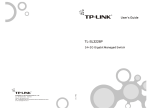
1
COPYRIGHT & TRADEMARKS
Specifications are subject to change without notice.
is a registered
trademark of TP-LINK Technologies Co., Ltd. Other brands and product names are
trademarks or registered trademarks of their respective holders.
No part of the specifications may be reproduced in any form or by any means or used to
make any derivative such as translation, transformation, or adaptation without
permission from TP-LINK Technologies Co., Ltd. Copyright © 2005 TP-LINK
Technologies Co., Ltd. All rights reserved.
COPYRIGHT & TRADEMARKS ......................................................................... 0
Package Contents............................................................................................................. 1
Chapter 1: About this User's Guide ................................................................................... 2
1.1 Usage................................................................................................................... 2
1.2 Assumpsit............................................................................................................. 2
1.3 Overview of this User's Guide .............................................................................. 2
Chapter 2: Introduction...................................................................................................... 3
2.1 Features............................................................................................................... 3
Chapter 3: Installation ....................................................................................................... 4
3.1 Installation............................................................................................................ 4
3.2 Rack Installation................................................................................................... 4
3.3 Power On ............................................................................................................. 5
3.4 Initialization .......................................................................................................... 5
Chapter 4: Explanation of Switch Appearance and the Method of Connecting Switch...... 6
4.1 Front Panel .......................................................................................................... 6
4.2 Rear Panel ........................................................................................................... 6
4.3 LED ...................................................................................................................... 7
4.4 Optional Extension Modules ................................................................................ 7
4.5 Connection........................................................................................................... 7
Chapter 5: Installation and the Usage of the Remote Management Software................... 8
5.1 Steps of Installation of the Remote Management Software —SSU...................... 8
5.2 Usage of Remote Configuration Software -- SSU ................................................ 8
5.2.1 Add............................................................................................................. 9
5.2.2 Connection............................................................................................... 13
5.2.3 Configuration ........................................................................................... 14
5.2.4 Exit........................................................................................................... 21
Chapter6 TELNET/Out-of-Band Management ................................................................ 22
6.1 Introduction ........................................................................................................ 22
6.2 How to connect Out-of-Band.............................................................................. 22
6.3 How to connect TELNET.................................................................................... 24
6.4 The interface and operating way of TELNET/Out-of-Band ................................. 25
6.5 Configuration of Out-of-Band Management ....................................................... 25
Appendix A Technical Specifications ............................................................................... 33
TL-SF2226P+/TL-SL2226P+
Remote Smart Switch User Guide
Package Contents
The following contents should be found in your box:
One Switch
One AC power cable
One Serial cable
One User's Guide
One Resource CD
Two mounting brackets and screws
Note: If any of the listed contents are damaged or missing, please contact the retailer
from whom you purchased the Switch for assistance.
-1-
TL-SF2226P+/TL-SL2226P+
Remote Smart Switch User Guide
Chapter 1: About this User's Guide
Thank you for purchasing TL-SF2226P+/TL-SL2226P+ Remote Smart Switch! The
TL-SF2226P+/TL-SL2226P+ provides powerful management functions. With the feature
of high-performance, easy to use and economical, the TL-SF2226P+/TL-SL2226P+ is
one of the best choice for you.
1.1 Usage
This User's Guide tells you how to use the TL-SF2226P+/TL-SL2226P+ Remote Smart
Switch.
1.2 Assumpsit
The Switch indicated in the User's Guide is the TL-SF2226P+/TL-SL2226P+ Remote
Smart Switch.
1.3 Overview of this User's Guide
Chapter 1
Chapter 2
Chapter 3
Chapter4
Chapter5
Chapter6
Appendix
About the User's Guide
Introduction. Describes the switch and its features
Installation. Helps you to get started with the basic installation of the switch
Explanation of switch appearance and the method of connecting switch
Installation and Usage of Remote Management Software
TELNET/Out-of-Band Management
Technical Specifications
-2-
TL-SF2226P+/TL-SL2226P+
Remote Smart Switch User Guide
Chapter 2: Introduction
This part simply describes the features of TL-SF2226P+/TL-SL2226P+ Remote Smart
Switch. For more details, please refer to Chapter 4.
2.1 Features
Supports remote management
Supports Out-of-Band management
Supports Telnet management
Provides 10/100M switch base function
24 10Base-T/100Base-TX RJ-45 ports with auto-MDI/MDIX
The TL-SL2226P+ provides two 10Base-T/100Base-TX/1000Base-T, 100Base-FX/
1000Base-SX/LX extension slots, supporting 10/100/1000Mbps module card, e.g.
TL-SM201/TL-SM301 serial fiber/twist pair module card.
The TL-SF2226P+ provides two independent extension slots, supporting
10/100Mbps module card, e.g. TL-SM201 serial fiber/twist pair module card.
Supports port auto-negotiation function, negotiating the speed and duplex mode
between the devices automatically
Supports full-duplex/half-duplex flow control
Provides Maximum 26 Port-based VLAN and 32 IEEE802.1Q based Tag VLAN
Supports MAC address learning and aging with programmable age time
Supports MAC Binding.
Supports QOS configuration (802.1p Base QOS)
Supports Trunk management.
Supports bandwidth Management
Supports upgrading switch software with COM and TFTP
-3-
TL-SF2226P+/TL-SL2226P+
Remote Smart Switch User Guide
Chapter 3: Installation
3.1 Installation
Follow these steps to install the switch:
The surface must support at least 5kg
The power source must be within 1.5m
Check the cable to make sure the connection to AC power
Leave enough space for the ventilation
3.2 Rack Installation
The TL-SF2226P+/TL-SL2226P+ can be mounting in an EIA standard size 19 inches
rack.
1.
Attach a mounting bracket to each side of the TL-SF2226P+ with the screws
provided.
2.
Slide the TL-SF2226P+/TL-SL2226P+ into the Rack.
3.
Use the screws to secure the switch to the Rack.
Figure 3-1 The view of attaching the mount brackets on the TL-SF2226P+
-4-
TL-SF2226P+/TL-SL2226P+
Remote Smart Switch User Guide
Figure 3-2 The view of mounting the TL-SF2226P+ in the rack
3.3 Power On
The TL-SF2226P+/TL-SL2226P+ can be used with the power source in the range of 100
to 240 VAC, 50 to 60Hz.
The internal power system of the TL-SF2226P+/TL-SL2226P+ can automatically adjust
the operating power according to the power input. The POWER LED will be light when
power on.
3.4 Initialization
Turn on the power, the switch will automatically initialize and the LEDs will be light as
follows:
At the time you turn on the power, if the LEDs of slot1 and slot2 on the front panel are
light, which means there are two module cards in slot1 and slot2. The LEDs of Port 1- 24
will turn out after two seconds that indicates the system is resetting. The CUP LED
flashing means the switch starts to work in good condition.
Caution: As a precaution in the event of a power failure, unplug the switch. When the
power resumed, plug the switch back in.
All the pictures are based on the TL-SF2226P+ in the manual. The pictures of
TL-SL2226P+ are almost the same as TL-SF2226P+.
-5-
TL-SF2226P+/TL-SL2226P+
Remote Smart Switch User Guide
Chapter 4: Explanation of Switch Appearance and the
Method of Connecting Switch
This chapter covers more details about front panel, rear panel, LED and extension
module of the switch.
4.1 Front Panel
There are 24 10/100Mbps ports and LED indicators on the front panel of the
TL-SF2226P+.
1
3
5
7
9
11
13
15
17
19
21
23
2
4
6
8
10
12
14
16
18
20
22
24
Figure 4-1 Front Panel of the TL-SF2226P+
4.2 Rear Panel
Slot 1
Slot 2
Console
TX
RX
TX
RX
110-260V
50-60Hz 0.6A
Figure 4-2 Rear Panel of the TL-SF2226P+
There is a power switch, a power connector, a console (RS232) port and 2 extension
module slots on the rear panel.
Power Connector
The AC power connector is a standard three-pronged connector that supports the power
cord. Plug the female connector of the provided power cord into the socket, and the male
side of the cord into a power outlet. Supported input voltage range is from 100 to 240
VAC at 50-60Hz.
Console Port
The console port or RS232 port on the right of the rear panel is the connection port with
PC when Out-of-Band management. (For more details, please refer to Chapter 6).
Module Slot
The module slots can be inserted with 10/100M module card (TL-SF2226P+) or
10/100/1000M or a 1000M Base-X module card (TL-SL2226P+).
-6-
TL-SF2226P+/TL-SL2226P+
Remote Smart Switch User Guide
4.3 LED
LEDs, including Power LED, 100Mbps LED, Link/Act LED, Slot1, Slot2 and CPU LED,
can detect and indicate the state of the switch. More details are as follows.
1
3
5
7
9
11
13
15
17
19
21
23
2
4
6
8
10
12
14
16
18
20
22
24
Figure 4-3 LED Indicators view of TL-SF2226P+ Switch
Power LED
The power LED will be solid red when power on, or else, check the power connection.
Link/Act LED
The LED is lit when there is a secure connection to a device at any of the ports.
100Mbps LED
When the normal ports connect a 100Mbps device, the corresponding LED is green, an
unlit LED indicates a connection speed of 10Mbps.
Slot LED
Slot1, Slot2 LED indicates that whether there is a module card in the module slot.
CPU LED
The CPU LED flashing means that the switch works in good condition.
4.4 Optional Extension Modules
Before you install any modules, remember to turn off the power at first.
After you take out the board on the slot, put the module into the extension slot. The
TL-SF2226P+ can auto-identify the module and configure it automatically.
The TL-SF2226P+ can be used with TL-SM201 100M series modules.
Caution: Never install the modules without turning off the power.
4.5 Connection
The TL-SF2226P+ supports MDI/MDIX, so you can use every port as a normal port or an
uplink port. Each port is independent, which makes the connection very easy.
Caution: When the connection is ok, the Link/Act is light, or else, make sure the twist
pair is working and the power is on.
-7-
TL-SF2226P+/TL-SL2226P+
Remote Smart Switch User Guide
Chapter 5: Installation and the Usage of the Remote
Management Software
The TL-SF2226P+/TL-SL2226P+ is a smart switch, you can configure it with the remote
Management software shipped with the switch, It’s very convenient for you to manage
the switch. After install the software under windows OS, you can manage several
switches at the same time.
Caution: Between the remote management software and the telnet management
described in the next chapter, you can only choose one to manage the switch.
5.1 Steps of Installation of the Remote Management Software
—SSU
1)
Installation requirement: Windows OS, Supporting TCP/IP Protocol.
2)
Installation steps: Run the setup.exe, and following the wizard to finish the setup. If
you want to change the default path, click Browse, Input or choose the path you
want, click OK and then next to finish the setup. As figure 5-1.
Figure 5-1
5.2 Usage of Remote Configuration Software -- SSU
The interface of SSU application is friendly and easy to use. Generally speaking, there
-8-
TL-SF2226P+/TL-SL2226P+
Remote Smart Switch User Guide
are four steps on configuring the switch.
1)
Add
2)
Connection
3)
Configuration
4)
Exit
Caution: When you use the switch for the first time, you must reset the IP address and
gateway of the switch. The witch default IP address is 192.168.0.100(for more details,
please refer to Chapter 5).
Here are details on how to use the SSU application.
Before configuration, make sure that the PC and the switch which the SSU application
installed can see each other. You can ping the switch, check whether they can see each
other. If they can't see each other, check whether the power is on and the twisted pair is
well connected. If all is ok, run the SSU application, you can see the initialized interface
of the SSU application. As figure 5-2.
Figure 5-2
5.2.1 Add
1)
First, add a device group. The name of the new group can't be the same as the
names that already existed in the application. After adding the group, you can
rename the group and delete it at any time. Here are some methods as follows.
a)
Click main menu->System->Add Group. As figure 5-3.
-9-
TL-SF2226P+/TL-SL2226P+
Remote Smart Switch User Guide
Figure 5-3
Click Add Group, you can see the dialog. As figure 5-4
Figure 5-4
b)
Click the right button at Please Add Group on initialized interface and then pop
up a menu, click Add Group. As figure 5-5
- 10 -
TL-SF2226P+/TL-SL2226P+
Remote Smart Switch User Guide
Figure 5-5
c)
Click the add group icon on the tool bar. As figure 5-6.
Figure 5-6
2)
Add device and node in device group. In device group, you can add device and
node, which are just like file and folder. The hiberarchy of node and device of a
group are not more than five. If there is the fifth hiberarchy, the fifth hiberachy can
only be a device. The device and node can be changed at any time you want. But in
a device group, the name of device and node must be different from each other, so
is the IP Address. The length of their name is not more than 255, the password
length is not more than 7.
- 11 -
TL-SF2226P+/TL-SL2226P+
Remote Smart Switch User Guide
Open the group you added just now and click the right button on the device name,
then there will pop up a menu. As figure 5-7.
Figure 5-7
Click Add Dev/ Node, you will see a dialog. As figure 5-8.
Figure 5-8
After adding device and node, you can see the interface as figure 5-9.
- 12 -
TL-SF2226P+/TL-SL2226P+
Remote Smart Switch User Guide
Figure 5-9
Look at the device icon carefully, if the color of the icon is red, it means that the
device can't communicate with the PC. Please check whether the power is on, the
twisted pair is well connected and the ping is ok.
If all is ok, you can click the save icon to save information of the device.
5.2.2 Connection
Now you can connect the device. If the color of the device icon is green, click the right
button on the icon, then pop up a menu, click connect, you will see the interface as
figure 5-10.
Figure 5-10
- 13 -
TL-SF2226P+/TL-SL2226P+
Remote Smart Switch User Guide
The color of the port on the panel is yellow, which means that the port is in connection. If
it is red, it means that the port is forbidden to use. If the color of the port frame is red, it’s
said that the port is management port.
5.2.3 Configuration
If the device is well connected, you can configure the switch now.
5.2.3.1 Conventional Management
1.
Disconnect
When the device is in connection, if at the moment it does not need management, you
can choose the Close Group button to close the group.
2.
Reset
When the device is in connection, if resetting needed, click main menu ->Device->Reset,
a dialog will pop up. Click ok on the dialog, finally, the switch will be reset.
3.
Resume Factory Setting
When the device is in connection, if resuming factory setting needed, click main menu
->Device->Resume Factory Setting, a dialog will come out, click ok on the dialog, then
the switch will resume factory setting.
4.
Change Password
When the device is in connection, if you want to change password, click main
menu->Device->Change Password, a dialog will be pop up, you can change password
in the dialog, the length of password is not more than 7.
5.2.3.2 Configuration of Device
1.
VLAN Config
The TL-SF2226P+ can support three VLAN modes, no VLAN, port VLAN and tag VLAN.
Default Setting:
no VLAN.
Steps of Setting: If VLAN mode is no VLAN, or you want to change current VLAN
mode, you should select one mode you want to. Click main menu->config->Switch
VLAN Mode. As figure 5-11.
- 14 -
TL-SF2226P+/TL-SL2226P+
Remote Smart Switch User Guide
Figure 5-11
Current VLAN mode is shown in the combo box, select one mode you want in the combo
box and click OK. If you change the VLAN mode, the information of previous VLAN will
be lost and the switch will give new default information about VLAN. If the VLAN mode is
port VLAN, all ports will be in a VLAN. If the VLAN mode is tag VLAN, all ports will be in a
VLAN which tag's value is 1. After Configuring VLAN mode, you can configure VLAN now.
Click main menu->Config->VLAN Config, under the view, you will see the VLAN list box.
Double click the VLAN you wan to change. If the VLAN mode is port VLAN, select or
delete some ports you want to change in the pop-up dialog. As figure 5 -12.
Figure 5-12
If the VLAN mode is tag VLAN, Configure tag VLAN in the pop-up dialog. As figure 5-13.
For more details, please read the help file.
- 15 -
TL-SF2226P+/TL-SL2226P+
Remote Smart Switch User Guide
Figure 5-13
Now go back to the main menu->Config->VLAN Config->Config Effect, Only execute
this step, the Configuration will be valid. If the VLAN mode is not changed, this menu
can't be seen.
2.
TRUNK Config
TRUNK can transmit net data through a group of ports. The switch looks a TRUNK as a
big port regardless of it's composition.
Default setting:
no TRUNK.
Steps of setting: Click main menu->Config-> TRUNK Config->Config Effect or click
the TRUNK icon on toolbar. As figure 5-14.
Figure 5-14
Double click the TRUNK you want to config in the TURNK list box, TRUNK configuration
dialog will pop up, and you can config the TRUNK now. For more details, please refer to
- 16 -
TL-SF2226P+/TL-SL2226P+
Remote Smart Switch User Guide
help file.
Now go back to main menu->Config->TRUNK Config->Config Effect.
Figure 5-15
Only execute this step, the Configuration will be valid. If the TRUNK is not changed, this
menu can't be seen.
3.
Port Config
Click main menu->Config->Port Config or double click a port in the port list box. As
figure 5-16.
Figure 5-16
Now you can configure each parameter of the port except port priority.
1)
Mode: 10Base-T/100Base-TX Ports
Auto (default):
other end.
auto-test the speed and negotiate the duplex mode with the
- 17 -
TL-SF2226P+/TL-SL2226P+
Remote Smart Switch User Guide
10HD: 10Mbps, Half-Duplex.
10FD: 10Mbps, Full-Duplex.
100HD: 100Mbps, Half-Duplex.
100FD: 100Mbps, Full-Duplex
2)
Flow Control:
Disable: The port won't produce Flow Control packets and will discard the Flow
Control packets received.
Enable: The Switch will negotiate Flow Control on the specified port according to
Full-Duplex or Half-Duplex.
3)
Port Security: When you configure the Port Security of a port to be Enable, the
port won't learn any new MAC address. Furthermore, the port only transfers the
data accordant to static MAC Address. If the port does not bind any static MAC
address, the port will not transfer data. When the Port Security of a port is
disabled, the port will automatically learn any new MAC Address and transfer
data.
Default setting: Disable
4)
Default PVID: There is the choice only in the IEEE802.1Q Tag VLAN mode.
Every port on the Switch has a default VID which is the VID for an untag Tag
received by the port.
5)
Default Value: 1
6)
User Info: User Info just gives the port a description.
4.
Priority Config
Steps of Configuring Priority:
Click main menu->Config->Priority Config or click the priority icon on toolbar. As figure
5-17.
- 18 -
TL-SF2226P+/TL-SL2226P+
Remote Smart Switch User Guide
Figure 5-17
Now a dialog will be pop up. In the dialog, you should Enable QOS, set high priority and
low priority and select a priority class in the list box. For more details, please refer to help
file.
Figure 5-18
5.
Broadcast Storm Control
When the Broadcast Storm Control is enabled, it will be valid. Click main menu->
Config-> Broadcast Control and you can configure the Broadcast Storm Control. For
more details, please read help file.
6.
Static MAC Bind
Static MAC Bind can help you control the security of network more efficiently. When it
takes effect, the ports will not learn any new MAC Address. The switch can bind 128
MAC addresses at most. One port can bind several MAC Addresses, but one MAC
address only can be bound by one port. Click main menu->Config->Static MAC Bind,
- 19 -
TL-SF2226P+/TL-SL2226P+
Remote Smart Switch User Guide
you can see the interface as follows. For more details, please refer to help file.
Figure 5-19
7.
MAC Aging Time
Dynamic forwarding table entries, which are made up of the source and destination MAC
address and their associated port numbers, are deleted from the table if they are not
accessed within the aging time. The aging time can be from 300 to 765 seconds.
Steps of Setting: Click main menu->Config->MAC Aging Time or click the MAC Aging
Time icon on the toolbar, then configure MAC Aging Time in the pop-up dialog.
8.
Change IP
Click main menu->Config->Change IP, you will see the interface as follows.
Figure 5-20
The IP and Gateway before changed is current IP and Gateway of the switch. Through
this dialog, you can change the switch IP and Gateway. This operation will cause the
switch disconnect.
- 20 -
TL-SF2226P+/TL-SL2226P+
Remote Smart Switch User Guide
Caution: After change, if you can't connect with the switch, you can use RS232 to
connect the switch and get the switch IP.
9.
Switch VLAN Mode
The TL-SF2226P+ can support three VLAN modes, no VLAN, port VLAN and tag VLAN.
You can only choose one mode of the three as the current switch VLAN Mode.
10.
System Auto Time
Click main menu->Config->System Auto Time, you can configure the time in the text
box. The range of System Auto Time is from 20 minutes to 6000 minutes.
Time will count after successful connection. When time is up to System Auto Time, a
dialog will be pop up. If you want to continue the management, time will count again, else
the switch will be disconnected after 30 seconds.
5.2.4 Exit
After you configuring the switch, if you want to exit the program, click main
menu->System->Exit.
- 21 -
TL-SF2226P+/TL-SL2226P+
Remote Smart Switch User Guide
Chapter6 TELNET/Out-of-Band Management
6.1 Introduction
Through TELNET you can realize Remote Log in to manage the Switch. Out-of-Band
Management manages the switch locally through the console port, without occupying the
bandwidth.
Though TELNET and Out-of-Band have different presentation, their management
contents are the same, both of them can be used to configure the switch's characters.
Caution: Out-of-Band management and remote management (SSU management and
TELNET management) can log into the switch at the same time, the last change will be
saved in the switch. SSU management and TELNET management can not log in to
manage the switch at the same time.
6.2 How to connect Out-of-Band
Out-of-Band Management needs a terminal or a HyperTerminal.
First, connect the switch and the PC by the console cord. Then, run HyperTerminal.
Refer to the following figure to configure the HyperTerminal.
- 22 -
TL-SF2226P+/TL-SL2226P+
Remote Smart Switch User Guide
Figure 6-1
The speed of the console port is 19200bps. The data bit is 8 bit. There is not Parity Test
and flow control. The Stop bit is 1.Now you will see the interface as follows.
Figure 6-2
Input user name and password, the default user name and password are admin, you can
change it after logging in.
- 23 -
TL-SF2226P+/TL-SL2226P+
Remote Smart Switch User Guide
Figure 6-3
6.3 How to connect TELNET
Connect the management workstation to the management port on the switch. You can
directly use TELNET command on the command DOS prompt in the Windows
Attachment.
The parameter following the TELNET command is the IP address of the switch which
can be revised adapting to the network. However, when you reuse TELNET to access,
the parameter will be the switch's IP address newly set. Here is an example: telnet
222.88.88.49, you will see the interface as follows.
Figure 6-4
- 24 -
TL-SF2226P+/TL-SL2226P+
Remote Smart Switch User Guide
Input user name and password and you can manage the switch.
If you can not log in, check whether the network is working, check whether there is other
user who has already logged on. (Only one user can access the switch at one time
through TELNET.)
6.4 The interface and operating way of TELNET/Out-of-Band
No matter through TELNET or Out-of-Band Management, the users have two rights.
Admin:
the control right to manage the switch
Guest:
the read right for port of objects Admin visits
6.5 Configuration of Out-of-Band Management
Caution: When you configure the switch, if you want to move the cursor, just press W
or S, if you want to enter an interface, just press enter. The software is very easy to use,
just doing operation according to the prompt given by the software.
1)
Switch Config
Switch Config provides you feature parameters of the switch, you can configure them
directly. For how to configure them, you can refer to chapter 4. Here are some notes you
should pay attention to. Press enter you will see the following interface.
Figure 6-5
Port Management
In the interface, you can change properties of the port you want to, including flow control,
port security, port state, bandwidth management and PVID and so on, you also can know
the link status, real working mode and port type.
The link status, real working mode and port type of the switch can only be read and will
be refreshed in 10 seconds. If the color of the link status of one port is opposite to others,
- 25 -
TL-SF2226P+/TL-SL2226P+
Remote Smart Switch User Guide
it means that the port is connecting with remote management. You can not shut down the
port in order that the remote connection can't be interrupted. You can edit properties of
the ports with the space key. If the VLAN type is Tag based VLAN, the PVID can't be
visible and can't be edit. As figure 5-6.
Figure 6-6
VLAN Management
Figure 6-7
VLAN Management includes VLAN Mode, Port Based VLAN and 802.1Q VLAN. If you
change the VLAN Mode, the switch will lose the info of port PVID and static binding
address. The interface of VLAN Mode is as follows.
- 26 -
TL-SF2226P+/TL-SL2226P+
Remote Smart Switch User Guide
Figure 6-8
Port Based VLAN is as follows.
Figure 6-9
Only if current VLAN Mode is Port Based VLAN, you can see this interface, or you will
see an error message. If you want to edit VLAN, you can look a trunk as a big port.
802.1Q VLAN is as follows.
- 27 -
TL-SF2226P+/TL-SL2226P+
Remote Smart Switch User Guide
Figure 6-10
Only if the VLAN Mode is 802.1Q VLAN, you can see this interface, or you will see an
error massage. The configuration method is similar to Port Based VLAN.
If the VLAN state is DE, it means the VLAN is invalid. U means untag, T means tag.
TRUNK Management
TRUNK Management interface as follows:
Figure 6-11
Before you enable a TRUNK, you must make the properties of the 4 ports be the same. If
you synchronously configure VLAN, in a VLAN, the four ports must exist or be deleted at
the same time. If the VLAN Mode is 802.1Q VLAN, the ports must have the same tag
- 28 -
TL-SF2226P+/TL-SL2226P+
Remote Smart Switch User Guide
rule when they are in the same VLAN. When you enable or disable a TRUNK, the switch
will lose the info of static binding address which is relate to the TRUNK or the 4 ports.
MAC Table Aging Time
MAC Table Aging Time interface is as follows:
Figure 6-12
Priority Management
Priority Management interface is as follows, when the sate is close, other parameters
can't be changed.
Figure 6-13
Static MAC Table
Static MAC Table interface is as follows:
- 29 -
TL-SF2226P+/TL-SL2226P+
Remote Smart Switch User Guide
Figure 6-14
Press Enter, you will see the interface as follows.
Figure 6-15
There are three operations in Static MAC Table, add, delete and edit. The switch can bind
128 MAC at most, including Enable and Disable.
Caution: If you configure the Static MAC Table, it will take effect immediately, you
needn't save it.
Broadcast Storm
Broadcast Storm interface is as follows. When Broadcast State is Disable, other
parameters can't be changed.
- 30 -
TL-SF2226P+/TL-SL2226P+
Remote Smart Switch User Guide
Figure 6-16
2)
Network Config
Network Config interface is as follows, you can change the switch's IP, gateway, you can
not change the switch's MAC address.
Figure 6-17
Press w or s key to move cursor, press space to edit the switch's IP address, Default
gateway. Input the new IP address and gateway, press enter. If you input a valid IP or
gateway, you will get an error message. If you want to save the configuration, press ctrl +
s and the switch will restart.
Make sure that the network configuration is correct before you save it. If you don't want to
save it, press Esc to quit.
- 31 -
TL-SF2226P+/TL-SL2226P+
3)
Remote Smart Switch User Guide
Factory Reset
This operation will lead to factory set of the switch. All config configured by the user will be
valid except network config and user password. The operation will make the switch
restart.
4)
Change Password
The password which can be changed is user password, not administrator password. The
length of the password is not more than 7, the password can be null. When you log on with
user password, if you want to change user password, you should provide the older user
password. When you log on with administrator password, you can change the password
directly.
5)
Firmware Update
There are two ways of updating the switch, COM update and TFTP update. Here is an
introduction of TFTP update.
TFTP update
Make sure the switch and the PC is well connected through UDP port. You can
use ping to check whether the PC and the switch can communicate or not. For
example, if the switch's IP is 222.88.88.41, you can input ping 222.88.88.41 in the
MS-DOS interface. If ping is ok, that means the PC and the switch is well
connected.
Edit Update_SF2226P+ 201.bat file which can be download at our website:
www.tp-link.com. Change the IP 192.168.0.100 into the switch's real IP and save
it.
Log on the switch and run firmware update.
Before the timer reduces to zero, run Update_SF2226P+ 201 file and wait till the
switch is successfully updated. It will take you about 10-15 seconds.
If you there is error during updating the switch, the system will give you the prompt,
Rom test fail, update please, you must update the switch again, or the switch will
not work normally.
6)
Logout system
When you complete the configuration, go back to the main menu, move the cursor to
logout system and press enter, then you quit the Out-of-Band management.
Caution: If you do not do any operation to the switch for a long time (about 250seconds),
the system will logout automatically.
- 32 -
TL-SF2226P+/TL-SL2226P+
Remote Smart Switch User Guide
Appendix A Technical Specifications
TL-SF2226P+
Standards
IEEE802.3 10BASE-T IEEE802.3u 100BASE-TX/FX
Protocol
CSMA/CD Ethernet
Data Transfer
Ethernet: 10Mbps(half duplex), 20Mbps(full duplex)
Fast Ethernet: 100Mbps(half duplex), 200Mpbs(full duplex)
Topology
Star
Network Media
(Cable)
10Base-T: UTP category 3, 4, 5 cable (100m)
100Base-TX: UTP category 5 cable (100m)
100Base-FX: 9/125μm or 50/125μm or 62.5/125μm fiber
cable, SC/ST type
Number
of
RJ-45 ports
Basic
24 UTP/STP MDI/MDIX ports
Module Slot
Two independent module slots
Transmits Method
Store-and-Forward
Power Supply
100-240V ~ 50-60Hz 0.6A (internal universal power supply)
Power Consumption
Lower than 15 watts
Environment
Operating temperature: 0℃~40℃ (32℉~104℉)
Storage temperature: -40℃ – 70℃ (-40℉~158℉)
Storage humidity: 5% ~ 90% (non-condensing)
Dimension(W x H x D)
17.3 in. × 10.2 in. × 1.9 in. (440mm × 260mm × 47mm)
TL-SL2226P+
Standards
IEEE802.3 10 Base -T Ethernet
IEEE802.3u 100 Base -TX/FX Fast Ethernet
IEEE802.3ab 1000 Base -T Giga Ethernet
IEEE802.3z 1000 Base -SX/LX Giga Ethernet
IEEE802.3 Frame type: Clarity
Protocol
CSMA/CD Ethernet
Data Transfer
Ethernet: 10Mbps(half duplex), 20Mbps(full duplex)
Fast Ethernet: 100Mbps(half duplex), 200Mpbs(full duplex)
Giga Ethernet: 2000Mpbs(full duplex)
Topology
Star
Network Media
(Cable)
10Base-T: UTP category 3, 4, 5 cable (100m)
100Base-TX: UTP category 5 cable (100m)
1000Base-T: UTP category 5 cable (100m)
100Base-FX: 9/125μm or 50/125μm or 62.5/125μm fiber
cable, SC/ST type
1000Base-SX/LX: 9/125μm or 50/125μm or 62.5/125μm fiber
cable, SC/ST type
Number
of
RJ-45 ports
Basic
24 UTP/STP MDI/MDIX ports
- 33 -
TL-SF2226P+/TL-SL2226P+
Remote Smart Switch User Guide
Module Slot
Two independent module slots
Transmits Method
Store-and-Forward
Power Supply
100-240V ~ 50-60Hz 0.6A (internal universal power supply)
Power Consumption
Lower than 15 watts
Environment
Operating temperature: 0℃ ~ 40℃ (32℉~104℉)
Storage temperature: -40℃ – 70℃ (-40℉~158℉)
Storage humidity: 5% ~ 90% (non-condensing)
Dimension(W x H x D)
17.3 in. × 10.2 in. × 1.9 in. (440mm × 260mm × 47mm)
- 34 -