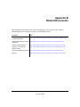
1
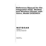
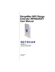
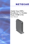
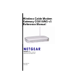
Wireless Cable Modem
Gateway CG814WG v3
Reference Manual
NETGEAR, Inc.
4500 Great America Parkway
Santa Clara, CA 95054 USA
202-10297-01
June 2007
© 2007 by NETGEAR, Inc. All rights reserved.
Trademarks
NETGEAR is a trademark of NETGEAR, Inc. Microsoft, Windows, and Windows NT are registered trademarks of
Microsoft Corporation. Other brand and product names are registered trademarks or trademarks of their respective
holders.
Statement of Conditions
In the interest of improving internal design, operational function, and/or reliability, NETGEAR reserves the right to
make changes to the products described in this document without notice.
NETGEAR does not assume any liability that may occur due to the use or application of the product(s) or circuit
layout(s) described herein.
FCC Warning Statement
This device complies with Part 15 of the FCC Rules. Operation is subject to the following two conditions:
(1) this device may not cause harmful interference, and
(2) this device must accept any interference received, including interference that may cause undesired operation.
This equipment has been tested and found to comply with the limits for a class B digital device, pursuant to part 15 of the
FCC Rules. These limits are designed to provide reasonable protection against harmful interference in a residential
installation.
This equipment generates, uses and can radiate radio frequency energy and, if not installed and used in accordance with
the instructions, may cause harmful interference to radio communications. However, there is no guarantee that
interference will not occur in a particular installation. If this equipment does cause harmful interference to radio or
television reception, which can be determined by turning the equipment off and on, the user is encouraged to try to
correct the interference by one or more of the following measures:
•
Reorient or relocate the receiving antenna.
•
Increase the separation between the equipment and receiver.
•
Connect the equipment into an outlet on a circuit different from that to which the receiver is connected.
•
Consult the dealer or an experienced radio/TV technician for help.
CAUTION: Any changes or modifications not expressly approved by the party responsible for compliance could void
the user’s authority to operate the equipment.
Prohibition of Co-location
This device and its antenna(s) must not be co-located or operating in conjunction with any other antenna or transmitter.
Safety Information
To maintain compliance with FCC’s RF exposure guidelines, this equipment should be installed and operated with
minimum distance of 20 cm between the radiator and your body. Use the supplied antenna.
Declaration of Conformity for R&TTE directive 1999/5/EC
Essential requirements – Article 3. Protection requirements for health and safety – Article 3.1a. Testing for electric
safety according to EN 60950-1 has been conducted. These are considered relevant and sufficient. Protection
ii
v1.0, June 2007
requirements for electromagnetic compatibility – Article 3.1b. Testing for electromagnetic compatibility according to
EN 301 489-1 and EN 301 489-17 has been conducted. These are considered relevant and sufficient. Effective use of the
radio spectrum – Article 3.2. Testing for radio test suites according to EN 300 328- 2 has been conducted. These are
considered relevant and sufficient.
Bestätigung des Herstellers/Importeurs
Es wird hiermit bestätigt, daß das CG814WG v3 Wireless Cable Modem Gateway gemäß der im BMPT-AmtsblVfg 243/
1991 und Vfg 46/1992 aufgeführten Bestimmungen entstört ist. Das vorschriftsmäßige Betreiben einiger Geräte (z.B.
Testsender) kann jedoch gewissen Beschränkungen unterliegen. Lesen Sie dazu bitte die Anmerkungen in der
Betriebsanleitung.
Das Bundesamt für Zulassungen in der Telekommunikation wurde davon unterrichtet, daß dieses Gerät auf den Markt
gebracht wurde und es ist berechtigt, die Serie auf die Erfüllung der Vorschriften hin zu überprüfen.
Certificate of the Manufacturer/Importer
It is hereby certified that the CG814WG v3 Wireless Cable Modem Gateway has been suppressed in accordance with the
conditions set out in the BMPT-AmtsblVfg 243/1991 and Vfg 46/1992. The operation of some equipment (for example,
test transmitters) in accordance with the regulations may, however, be subject to certain restrictions. Please refer to the
notes in the operating instructions.
Federal Office for Telecommunications Approvals has been notified of the placing of this equipment on the market
and has been granted the right to test the series for compliance with the regulations.
Technical Support
Thank you for choosing Netgear product(s). Please register online and take advantage of the technical support resources
such as Netgear online knowledge base. Technical support is available 24 hours a day, seven days a week; please call
your Cable Internet Service Provider.
Product and Publication Details
Model Number:
CG814WG v3
Publication Date:
June 2007
Product Family:
Product Family
Product Name:
CG814WG v3 Wireless Cable Modem Gateway
Home or Business Product:
Home
Language:
English
Publication Part Number:
202-10297-01
iii
v1.0, June 2007
iv
v1.0, June 2007
Contents
About This Manual
Conventions, Formats and Scope ..................................................................................... 1
How to Use This Manual ................................................................................................... 2
How to Print this Manual .................................................................................................... 2
Chapter 1
Connecting the Gateway to the Internet
Package Contents ..........................................................................................................1-1
Front Panel ...............................................................................................................1-1
Rear Panel ...............................................................................................................1-3
What You Need Before You Begin ..................................................................................1-3
Hardware Requirements ..........................................................................................1-3
LAN Configuration Requirements ............................................................................1-4
Internet Configuration Requirements .......................................................................1-4
Connecting the CG814WG v3 Gateway .........................................................................1-4
Installation ................................................................................................................1-4
Chapter 2
Wireless Configuration
Wireless Placement and Range Guidelines ...................................................................2-2
SSID and Wireless Security Settings Form ....................................................................2-3
Viewing or Changing Wireless Settings ..........................................................................2-4
Turning on Access Control to Restrict Access by MAC Address ....................................2-6
How to Configure WEP (Wired Equivalent Privacy) .......................................................2-8
How to Configure WPA .................................................................................................2-10
Chapter 3
Content Filtering and Firewall Rules
Content Filtering .............................................................................................................3-1
Logs .........................................................................................................................3-2
Blocking Keywords, Sites, and Services ..................................................................3-2
Blocking Keywords and Domains .............................................................................3-3
i
v1.0, June 2007
Wireless Cable Modem Gateway CG814WG v3 Reference Manual
Services ...................................................................................................................3-4
Firewall Rules .................................................................................................................3-5
Port Forwarding ........................................................................................................3-6
Port Blocking ............................................................................................................3-7
Chapter 4
Managing Your Network
Maintenance ...................................................................................................................4-1
Gateway Status ........................................................................................................4-2
Signal Status ............................................................................................................4-3
Set Password ...........................................................................................................4-4
Backup Settings .......................................................................................................4-5
Event Log .................................................................................................................4-6
Advanced Settings ..........................................................................................................4-7
WAN Setup ..............................................................................................................4-7
Dynamic DNS ...........................................................................................................4-8
LAN IP Settings ........................................................................................................4-9
Diagnostics .............................................................................................................4-10
Remote Management Access ................................................................................ 4-11
UPnP ......................................................................................................................4-12
Chapter 5
Troubleshooting
Basic Functions ..............................................................................................................5-1
Using LEDs to Troubleshoot ....................................................................................5-2
Connecting to the Gateway’s Main Menu .......................................................................5-2
Troubleshooting the ISP Connection ..............................................................................5-3
Troubleshooting a TCP/IP Network Using a Ping Utility .................................................5-4
Testing the LAN Path to Your Gateway ....................................................................5-4
Testing the Path from Your PC to a Remote Device ................................................5-5
Appendix A
Technical Specifications and Factory Default Settings
Technical Specifications ................................................................................................. A-1
Factory Default Settings ................................................................................................ A-2
Appendix B
Related Documents
ii
Contents
v1.0, June 2007
About This Manual
The NETGEAR® CG814WG v3 Wireless Cable Modem Gateway Reference Manual describes
how to install, configure and troubleshoot the CG814WG v3 Wireless Cable Modem Gateway.
The information in this manual is intended for readers with intermediate computer and Internet
skills.
Conventions, Formats and Scope
The conventions, formats, and scope of this manual are described in the following paragraphs:
•
•
Typographical Conventions. This manual uses the following typographical conventions:
Italics
Emphasis, books, CDs, URL names
Bold
User input
Fixed
Screen text, file and server names, extensions, commands, IP addresses
Formats. This manual uses the following formats to highlight special messages:
Note: This format is used to highlight information of importance or special interest.
Tip: This format is used to highlight a procedure that will save time or resources.
Warning: Ignoring this type of note may result in a malfunction or damage to the
equipment.
iii
v1.0, June 2007
Wireless Cable Modem Gateway CG814WG v3 Reference Manual
•
Scope. This manual is written for the CG814WG v3 Gateway according to these
specifications:
Product Version
CG814WG v3 Wireless Cable Modem Gateway
Manual Publication Date
June 2007
For more information about network, Internet, firewall, and VPN technologies, see the links to the
NETGEAR website in Appendix B, “Related Documents”.
Note: Product updates are available on the NETGEAR, Inc. website at
http://kbserver.netgear.com.
How to Use This Manual
The HTML version of this manual includes the following:
•
Buttons,
at a time
and
, for browsing forwards or backwards through the manual one page
•
A
button that displays the table of contents and an
button. Double-click on a
link in the table of contents or index to navigate directly to where the topic is described in the
manual.
•
A
model.
•
Links to PDF versions of the full manual and individual chapters.
button to access the full NETGEAR, Inc. online knowledge base for the product
How to Print this Manual
To print this manual you can choose one of the following several options, according to your needs.
•
Printing a Page in the HTML View.
Each page in the HTML version of the manual is dedicated to a major topic. Use the Print
button on the browser toolbar to print the page contents.
•
Printing a Chapter.
Use the PDF of This Chapter link at the top left of any page.
iv
About This Manual
v1.0, June 2007
Wireless Cable Modem Gateway CG814WG v3 Reference Manual
–
–
–
Click the PDF of This Chapter link at the top left of any page in the chapter you want to
print. The PDF version of the chapter you were viewing opens in a browser window.
Your computer must have the free Adobe Acrobat reader installed in order to view and
print PDF files. The Acrobat reader is available on the Adobe website at
http://www.adobe.com.
Click the print icon in the upper left of the window.
Tip: If your printer supports printing two pages on a single sheet of paper, you can
save paper and printer ink by selecting this feature.
•
Printing the Full Manual.
Use the Complete PDF Manual link at the top left of any page.
–
Click the Complete PDF Manual link at the top left of any page in the manual. The PDF
version of the complete manual opens in a browser window.
–
Click the print icon in the upper left of the window.
Tip: If your printer supports printing two pages on a single sheet of paper, you can
save paper and printer ink by selecting this feature.
About This Manual
v
v1.0, June 2007
Wireless Cable Modem Gateway CG814WG v3 Reference Manual
vi
About This Manual
v1.0, June 2007
Chapter 1
Connecting the Gateway to the Internet
This chapter describes how to set up the CG814WG v3 Gateway on your Local Area Network
(LAN), connect to the Internet, and perform basic configuration.
Package Contents
The product package should contain the following items:
• CG814WG v3 Wireless Cable Modem Gateway
• AC power adapter
• Category 5 (CAT5) Ethernet cable
• USB cable
If any of the parts are incorrect, missing, or damaged, contact your NETGEAR dealer. Keep the
carton, including the original packing materials, in case you need to return the product for repair.
Front Panel
The front panel of the CG814WG v3 contains status LEDs.
Figure 1-1
1-1
v1.0, June 2007
Wireless Cable Modem Gateway CG814WG v3 Reference Manual
You can use the LEDs to verify connections. Table 1-1 lists and describes each LED on the front
panel of the CG814WG v3 Gateway.
Table 1-1. LED Descriptions
LED
Description
Power
• On: Power is supplied to the gateway.
• Off: Power is not supplied to the gateway.
Cable Link
• On (green): Configuration of the cable interface by your cable service provider
is complete.
• Off: Configuration of the cable interface is still in progress.
Upstream
Traffic
• Blink: Data is being transmitted to the cable interface.
• Off: The cable interface is idle.
Downstream
Traffic
• Blink: Data is being received from the cable interface.
• Off: The cable interface is idle.
Wireless
• On: The wireless Access Point is operating normally.
Blink: Data is being transmitted or received on the wireless interface.
LAN
(Local Area
Network)
•
•
•
•
•
On (green): The port has detected link with a 100 Mbps device.
Blink (green): Data is being transmitted or received at 100 Mbps.
On (yellow): The Local port has detected link with a 10 Mbps device.
Blink (yellow): Data is being transmitted or received at 10 Mbps.
Off: No link is detected on this port.
1-2
Connecting the Gateway to the Internet
v1.0, June 2007
Wireless Cable Modem Gateway CG814WG v3 Reference Manual
Rear Panel
The rear panel of the CG814WG v3 contains the connections identified below:
wireless antenna
USB port
reset button
coaxial cable to your cable service provider
4 Ethernet LAN ports
AC power adapter input
Figure 1-2
What You Need Before You Begin
You need these three things before you can connect your gateway to the Internet:
• A computer properly connected to the gateway as explained below.
• Active Data Over Cable Internet service provided by cable modem account.
• The Internet Service Provider (ISP) configuration information for your cable modem account.
Hardware Requirements
The CG814WG v3 Gateway connects to your LAN using either its twisted-pair Ethernet, USB or
802.11b or 802.11g wireless port.
To use the CG814WG v3 Gateway on your network, each computer must have either an installed
Ethernet Network Interface Card (NIC), USB Host port or 802.11b or 802.11g wireless adapter. If
the computer will connect to your network at 100 Mbps, you must use a Category 5 (CAT5) cable
such as the one provided with your gateway.
Connecting the Gateway to the Internet
1-3
v1.0, June 2007
Wireless Cable Modem Gateway CG814WG v3 Reference Manual
LAN Configuration Requirements
For the initial connection to the Internet and configuration of your gateway, connect a computer to
the gateway which is set to automatically get its TCP/IP configuration from the gateway via
DHCP.
Note: For help with DHCP configuration, see the link to the online document “Internet
Networking and TCP/IP Addressing” in Appendix B.
Internet Configuration Requirements
Depending on how your ISP set up your Internet account, you will need one or more of these
configuration settings to connect your gateway to the Internet:
• Host and Domain Names
• ISP Domain Name Server (DNS) Addresses
• Fixed or Static IP Address
Connecting the CG814WG v3 Gateway
Note: Install and set up the CG814WG v3 Gateway using an Ethernet or USB
connection to your computer first. Then configure the wireless settings. See
Chapter 2, “Wireless Configuration” for instructions for wireless settings.
Installation
Follow these steps to install your gateway:
1. Connect the gateway.
a. Turn off your computer.
1-4
Connecting the Gateway to the Internet
v1.0, June 2007
Wireless Cable Modem Gateway CG814WG v3 Reference Manual
b. Using the coaxial cable provided by your cable company, connect the CG814WG v3 cable
port (A) to your cable line splitter or outlet.
A
Figure 1-3
c. Connect the gateway to your computer with either an Ethernet or USB cable.
Note: The USB connection option is only available for Windows PCs. Also,
Windows 95 does not support USB without special operating system
upgrades and patches.
For an Ethernet connection, use the Ethernet cable that shipped with your gateway to
connect a LAN port (B) to the Ethernet adapter in your computer.
B
Figure 1-4
Connecting the Gateway to the Internet
1-5
v1.0, June 2007
Wireless Cable Modem Gateway CG814WG v3 Reference Manual
Note: The CG814WG v3 Gateway uses Auto UplinkTM technology. Each local
Ethernet port senses whether the cable plugged into the port is attached to
a PC, or is attached to a switch or hub, which requires an uplink
connection. The port configures itself to accommodate either type of
cable. This eliminates the need for crossover cables.
For a USB connection, connect the USB cable to the USB port on your modem and to a
USB port on your computer.
d. Connect the power adapter to the CG814WG v3, and plug it into an outlet.
e. Turn on your computer. If software usually logs you in to your Internet connection, do not
run that software or cancel it if it starts automatically.
f.
Wait about 30 seconds for the lights to stop blinking, and then verify the following:
The power light is lit after turning on the gateway.
The cable link light is solid green, indicating a link has been established to the cable
network.
The LAN lights are lit for any connected computers.
2. For an Ethernet connection, go to Step 3. For a USB connection, install the USB driver.
a. For a USB connection you must install the USB driver. Insert the NETGEAR CD that
came with your gateway into the CD drive of your computer.
The Found New Hardware Wizard detects the gateway and prompts for the driver.
Figure 1-5
1-6
Connecting the Gateway to the Internet
v1.0, June 2007
Wireless Cable Modem Gateway CG814WG v3 Reference Manual
b. Browse to the Resource CD and install the USB driver by clicking through the Windows
wizard prompts.
3. Log in to the Gateway
Note: To connect to the gateway, your computer must be configured to obtain an IP
address automatically via DHCP. For instructions on how to do this, see the
link to “Preparing a Computer for Network Access” in Appendix B.
a. Using the computer that you first used to access your cable modem Internet service,
connect to the gateway by typing http://192.168.0.1 in the address field of your Internet
browser. A login window opens.
Figure 1-6
Note: For security reasons, the gateway has two sets of user names and passwords:
one for a parent and one for children. Only the parent’s login can be used to set
up Parental Control and MAC Filtering. The child’s login can configure all
other features of the gateway.
b. Log in to the gateway.
•
To log in as the parent, enter superuser for the user name and password for the
password, both in lower case letters.
•
To log in as the child, enter admin for the user name and password for the password,
both in lower case letters.
Connecting the Gateway to the Internet
1-7
v1.0, June 2007
Wireless Cable Modem Gateway CG814WG v3 Reference Manual
Note: If you cannot connect to the gateway, see “Basic Functions” in Chapter 5.
When you connect to the gateway the Gateway status screen opens.
Figure 1-7
4. Enter your Network Configuration.
•
WAN IP Address: The IP Address that you would for your gateway in dotted decimal
notation.
•
WAN Subnet Mask: The network number portion of an IP address. Unless you are
implementing subnetting, use 255.255.0.0 as the subnet mask.
•
WAN Default Gateway: This is the ISP’s router to which your gateway will connect.
•
WAN Primary and Secondary DNS: A DNS server is a host on the Internet that
translates Internet names (such as www.netgear.com) to numeric IP addresses. Typically
your ISP transfers the IP address of one or two DNS servers to your gateway during login.
If the ISP does not transfer an address, you must obtain it from the ISP and enter it
manually here. If you enter an address here, you should reboot your PCs after configuring
the gateway.
5. Click Apply to save your settings.
For more information about the Gateway Status screen see“Gateway Status” in Chapter 4.
1-8
Connecting the Gateway to the Internet
v1.0, June 2007
Chapter 2
Wireless Configuration
This chapter describes how to configure the wireless features of your CG814WG v3 Gateway. In
planning your wireless network, you should consider the level of security required. You should
also select the physical placement of your firewall in order to maximize the network speed.
Note: If you are configuring the gateway from a wireless PC and you change the
gateway’s SSID, channel, or wireless security settings, you will lose your wireless
connection when you click Apply. You must then change the wireless settings of
your PC to match the gateway’s new settings.
Set up wireless features for the gateway in this order:
1. Install the gateway as described in Chapter 1, “Connecting the Gateway to the Internet”. The
gateway should be working on your LAN before you set up the wireless features.
2. Plan the location for the gateway based on considerations in “Wireless Placement and Range
Guidelines” on page 2-2.
3. Use the form in section “SSID and Wireless Security Settings Form” on page 2-3 to keep track
of your settings.
4. Enter the wireless settings, and verify wireless connectivity as described in “Viewing or
Changing Wireless Settings” on page 2-4.
5. Set up wireless security as described in “Turning on Access Control to Restrict Access by
MAC Address” on page 2-6, , or “How to Configure WPA” on page 2-10.
For more information about wireless technology, see the link to “Wireless Communications” in
Appendix B.
2-1
v1.0, June 2007
Wireless Cable Modem Gateway CG814WG v3 Reference Manual
Wireless Placement and Range Guidelines
The range of your wireless connection can vary significantly based on the physical placement of
the gateway. The latency, data throughput performance, and notebook power consumption of
wireless adapters also vary depending on your configuration choices.
For best results, place your gateway:
•
Near the center of the area in which your PCs will operate.
•
In an elevated location such as a high shelf where the wirelessly connected PCs have line-ofsight access (even if through walls).
•
Away from sources of interference, such as PCs, microwave ovens, and 2.4 GHz cordless
phones.
•
Away from large metal surfaces.
•
Put the antenna in a vertical position to provide the best side-to-side coverage. Put the antenna
in a horizontal position to provide the best up-and-down coverage.
•
If using multiple access points, it is better if adjacent access points use different radio
frequency channels to reduce interference. The recommended channel spacing between
adjacent access points is 5 channels (for example, use channels 1 and 6, or 6 and 11).
The time it takes to establish a wireless connection can vary depending on both your security
settings and placement. WEP connections can take slightly longer to establish. Also, WEP
encryption can consume more battery power on a notebook computer.
2-2
Wireless Configuration
v1.0, June 2007
Wireless Cable Modem Gateway CG814WG v3 Reference Manual
SSID and Wireless Security Settings Form
For a new wireless network, print or copy this form and fill in the settings. For an existing wireless
network, the person who set up or is responsible for the network can get the settings. Be sure to set
the Regulatory Domain correctly as the first step.
•
SSID. The Service Set Identification (SSID) identifies the wireless local area network.
NETGEAR is the default SSID. However, you may customize it by using up to 32
alphanumeric characters. Write your customized SSID on the line below.
____________________________________________________
The SSID in the gateway is the SSID you configure in the wireless adapter card. All wireless
nodes in the same network must be configured with the same SSID.
•
Authentication.
Circle one: Open System or Shared Key. Choose Shared Key for more security.
To use Shared Key, all devices in the network must be set to Shared Key and have the same
keys in the same positions as those in the CG814WG v3.
•
WEP Encryption Keys. For all four keys, choose the Key Size. Circle one: 64, or 128 bits.
Key 1: ______________________________________________
Key 2: ______________________________________________
Key 3: ______________________________________________
Key 4: ______________________________________________
•
WPA-PSK (Pre-Shared Key) and WPA2-PSK. Record the WPA-PSK or WPA2-PSK key.
Key: _____________________________________________ (8-63 characters)
•
WPA and WPA2 RADIUS Settings. For WPA and WPA2, record the following settings for
the primary and secondary RADIUS servers.
Server Name/IP Address: _____________________________________________
Port: _____________________________________________
Shared Key: _____________________________________________
Use the procedures described in the following sections to configure the CG814WG v3. Store this
information in a safe place.
Wireless Configuration
2-3
v1.0, June 2007
Wireless Cable Modem Gateway CG814WG v3 Reference Manual
Viewing or Changing Wireless Settings
You can view or change the wireless settings for the gateway. If you want to make changes, make
sure to note the current settings first. See the “SSID and Wireless Security Settings Form” on
page 2-3.
1. Log in to the gateway using its default address of http://192.168.0.1 or at whatever IP address
the unit is currently configured Use the default user name of admin and default password of
password, or whatever password you have set up.
2. Click the Wireless Settings link to go to the Wireless Settings screen.
Figure 2-1
2-4
Wireless Configuration
v1.0, June 2007
Wireless Cable Modem Gateway CG814WG v3 Reference Manual
The settings in the Wireless Settings screen are explained in the following table.
Table 2-1. Wireless Settings
Settings
Wireless Network
Wireless Access
Point
Description
Name (SSID)
The SSID is also known as the wireless network
name. Enter a 32-character (maximum) name in this
field. The characters are case sensitive.
In a setting where there is more than one wireless
network, different wireless network names provide a
means for separating the traffic. Any device you want
to participate in a wireless network must use the
SSID.
Region
The location where the gateway is used.
Channel
The wireless channel used by the gateway. The
default is channel 6.
You should not need to change the wireless channel
unless you experience interference (shown by lost
connections and/or slow data transfers). Should this
happen, you may need to experiment with different
channels to see which is the best.
Enable Wireless Access Point On by default, you can also turn off the wireless radio
to disable access through this device. This can be
helpful for configuration, network tuning, or
troubleshooting activities.
Allow Broadcast Name (SSID) On by default, the gateway broadcasts its SSID,
allowing wireless stations which have a “null” (blank)
SSID to adopt the correct SSID. The default SSID is
NETGEAR.
If you disable broadcast of the SSID, only devices
that have the correct SSID can connect. This nullifies
the wireless network “discovery” feature of some
products such as Windows XP, but the data is still
fully exposed to a determined snoop using
specialized test equipment like wireless sniffers. For
this reason NETGEAR recommends that you also
enable wireless security.
Wireless Card
Access List
Turn Access Control On
Access control is disabled by default so that any
computer that is configured with the correct SSID
can connect. For information about access control,
see “Turning on Access Control to Restrict Access by
MAC Address” on page 2-6.
Wireless Configuration
2-5
v1.0, June 2007
Wireless Cable Modem Gateway CG814WG v3 Reference Manual
Table 2-1. Wireless Settings (continued)
Settings
Security Options
Description
Disable
Wireless security is disabled by default. After the
gateway is connected to the Internet, NETGEAR
strongly recommends that you implement wireless
security.
• WEP (Wired Equivalent
Privacy) 64-bit encryption
• WEP (Wired Equivalent
Privacy) 128-bit encryption
WEP security uses encryption keys.
Wired Equivalent Privacy (WEP) data encryption
provides data security. WEP Shared Key
authentication and WEP data encryption will block all
but the most determined eavesdropper.
You can select 64-bit or 128-bit encryption. See “How
to Configure WEP (Wired Equivalent Privacy)” on
page 2-8.
WPA-PSK
WPA2
WPA Enterprise
Wi-Fi Protected Access (WPA) data encryption
provides data security. The very strong
authentication along with dynamic per frame
rekeying of WPA make it virtually impossible to
compromise. Because this is a new standard,
wireless device driver and software availability may
be limited.
WPA-PSK uses authentication from a Radius
server. WPA2 uses a pre-shared key passphrase.
See “How to Configure WPA” on page 2-10.
Turning on Access Control to Restrict Access by MAC
Address
By default, any wireless PC that is configured with the correct SSID and WEP/WPA settings will
be allowed access to your wireless network. For increased security, you can restrict access to the
wireless network to only allow specific PCs based on their MAC addresses.
You can restrict access to only trusted PCs so that unknown PCs cannot wirelessly connect to the
CG814WG v3 Gateway. MAC address filtering adds an obstacle against unwanted access to your
network, but the data broadcast over the wireless link is fully exposed.
2-6
Wireless Configuration
v1.0, June 2007
Wireless Cable Modem Gateway CG814WG v3 Reference Manual
To restrict access based on MAC addresses:
1. Connect to the gateway and log in as described in “Viewing or Changing Wireless Settings” on
page 2-4.
Note: If you are configuring the gateway from a wireless computer, make sure to add
your computer’s MAC address to the Access List. Otherwise you will lose your
wireless connection when you click Apply. You must then access the gateway
from a wired computer, or from a wireless computer that is on the access
control list, to make any further changes.
2. Click Wireless Settings, and then select the Turn Access Control On check box.
When you enable access control, the access point only accepts connections from clients on the
selected access control list. This provides an additional layer of security.
3. Click the Setup Access List button to display the Access List.
Figure 2-2
The Access List displays a list of wireless clients that will have access to the wireless network
when the list is enabled.
Wireless Configuration
2-7
v1.0, June 2007
Wireless Cable Modem Gateway CG814WG v3 Reference Manual
4. Adjust the list as needed for your network. You can add a devices to the Access List using
either of the following methods:
a. If the computer is in the Connected Wireless Devices table, click the radio button of that
computer to capture its MAC address; or
b. Specify the MAC address of the device to be added to the Access List in the Add Access
Filter fields. The MAC address can usually be found on the bottom of the wireless device.
Note: If no Device Name appears when you enter the MAC address, you can type a
descriptive name for the computer that you are adding.
c. Click Add.
4. Click Apply to save these settings. Now, only devices on this list will be allowed to wirelessly
connect to the gateway.
How to Configure WEP (Wired Equivalent Privacy)
Note: If you use a wireless computer to configure wireless security settings, you will be
disconnected when you click Apply. Reconfigure your wireless computer to match
the new settings, or access the gateway from a wired computer to make further
changes.
To configure WEP data encryption:
1. Log in to the gateway using its default address of http://192.168.0.1 or at whatever IP address
the unit is currently configured. Use the default user name of admin and default password of
password, or the password you have set up.
2. Click the Wireless Settings link to go to the Wireless Settings screen.
3. Depending on the encryption strength that you want, select one of these options:
•
•
WEP (Wired Equivalent Privacy) 64-bit encryption
WEP (Wired Equivalent Privacy) 128-bit encryption
2-8
Wireless Configuration
v1.0, June 2007
Wireless Cable Modem Gateway CG814WG v3 Reference Manual
Settings for WEP encryption are shown on the screen:
Figure 2-3
4. Select the Authentication. Choose Open System, Shared Key, or Open System or Shared
Key. The default is Open System.
5. Enter the encryption settings:
•
WEP PassPhrase: To use a passphrase to generate the keys, enter a passphrase and click
Generate. This automatically creates the keys. Wireless stations must use the passphrase or
keys to access the gateway.
•
Key 1-Key4: You can manually enter the four data encryption keys. These values must be
identical on all computers and access points in your network. Enter ten hexadecimal digits
(any combination of 0-9, a-f, or A-F).
•
Select which of the four keys will be the default. Data transmissions are always encrypted
using the default key. The other keys can only be used to decrypt received data. The four
entries are disabled if WPA-PSK or WPA authentication is selected.
6. Click Apply to save your settings.
Note: If you use a wireless computer to configure WEP settings, you will be
disconnected when you click Apply. Reconfigure your wireless adapter to match
the new settings or access the gateway from a wired computer to make any further
changes.
Wireless Configuration
2-9
v1.0, June 2007
Wireless Cable Modem Gateway CG814WG v3 Reference Manual
How to Configure WPA
Note: Not all wireless adapters support WPA. Furthermore, client software is required on
the client. Windows XP and Windows 2000 with Service Pack 3 or above do
include the client software that supports WPA. The wireless adapter hardware and
driver must also support WPA. Consult the product documentation for your
wireless adapter and WPA client software for instructions on configuring WPA
settings.
To configure WPA in the gateway:
1. Log in to the gateway at the default LAN address of http://192.168.0.1 with the default user
name of admin and default password of password, or using whatever LAN address and
password you have set up.
2. Click Wireless Settings to go to the Wireless Settings screen.
3. Select WPA-PSK, WPA2-PSK, or WPA (Enterprise).
The settings shown on the screen depend on which Security Option you select.
WPA-PSK
WPA2-PSK
WPA (Enterprise)
Figure 2-4
4. For WPA-PSK or WPA2-PSK, enter the Passphrase. Click Apply to save your settings.
5. If you are using WPA (Enterprise) then enter the settings for the Radius Server. These settings
are required for communication with the primary Radius server. A secondary Radius server
can be configured, which is used on failure on Primary Radius Server.
•
Primary Radius Server IP Address: The IP address of the Radius Server. The default is
0.0.0.0
2-10
Wireless Configuration
v1.0, June 2007
Wireless Cable Modem Gateway CG814WG v3 Reference Manual
•
Radius Port: Port number of the Radius Server. The default is 1812.
•
Shared Key: This is shared between the Wireless Access Point and the Radius Server
while authenticating the supplicant.
6. Click Apply to save your settings.
Wireless Configuration
2-11
v1.0, June 2007
Wireless Cable Modem Gateway CG814WG v3 Reference Manual
2-12
Wireless Configuration
v1.0, June 2007
Chapter 3
Content Filtering and Firewall Rules
This chapter describes how to use Content Filtering and Firewall Rules for the CG814WG v3
Gateway to protect your network.
Note: You must log in as a parent (superuser) in order to access Content Filtering
features.
Content Filtering
Figure 3-1
Content Filtering features include Logs, Block Sites, and Services. Firewall rules can also be used
for content filtering.
3-1
v1.0, June 2007
Wireless Cable Modem Gateway CG814WG v3 Reference Manual
Logs
A log is a detailed record of the Denial of Service (DoS) attacks directed at your network. You can
use e-mail notification to receive these logs in an e-mail message. If you do not have e-mail
notification set up you can connect to the gateway to view the logs.
Figure 3-2
To receive logs by e-mail:
1. For the Contact Email Address, type an e-mail address to which the logs will be sent. Use a
full e-mail address (for example, [email protected]).
2. For the SMTP Server Name, type the outgoing SMTP mail server of your ISP (for example,
mail.myISP.com). If you leave this box blank, no alerts or logs will be sent.
3. Select the E-mail Alerts Enable check box.
4. Click Apply.
For information about event logs, see “Event Log” in Chapter 4.
Blocking Keywords, Sites, and Services
The gateway provides a variety of options for blocking Internet based content and
communications services. With its content filtering feature, the CG814WG v3 Gateway
prevents objectionable content from reaching your PCs. The CG814WG v3 allows you to control
access to Internet content by screening for keywords within Web addresses. It also has the
capability to block access to all sites except those that are explicitly allowed. Key content
filtering options include:
• Blocking access from your LAN to Internet locations that contain keywords that your specify.
• Blocking access to websites that you specify as off-limits.
• Allowing access to only websites that you specify as allowed.
3-2
Content Filtering and Firewall Rules
v1.0, June 2007
Wireless Cable Modem Gateway CG814WG v3 Reference Manual
Blocking Keywords and Domains
The CG814WG v3 Gateway allows you to restrict access to Internet content based on functions
such as Web address keywords and Web domains. A domain name is the name of a particular
website. For example, for the address www.NETGEAR.com, the domain name is
NETGEAR.com.
To block keywords and domains:
1. Log in to the gateway at its default LAN address of http://192.168.0.1 with its parent default
user name of superuser, default password of password, or using whatever password and LAN
address you have chosen for the gateway in parent mode.
2. Click the Block Sites link under the Content Filtering heading.
Figure 3-3
3. To use Keyword Blocking, select the Keyword Blocking Enable check box and then you can
enter up to eight keywords.
•
To enter a keyword, type it, and then click Add Keyword. The keyword will be shown in
the Keyword List.
•
If the keyword “XXX” is specified, the URL <http://www.badstuff.com/xxx.html> is
blocked.
•
If the keyword “.com” is specified, only websites with other domain suffixes (such as .edu
or .gov) can be viewed.
Content Filtering and Firewall Rules
3-3
v1.0, June 2007
Wireless Cable Modem Gateway CG814WG v3 Reference Manual
•
Enter the keyword “.” to block all Internet browsing access.
4. You can use the Domain List to create a list of allowed domains, or to create a list of denied
domains. Select the Domain Blocking Enable check box. Then you can add domains.
•
To add a domain, type the domain, and then click Add Domain. It is added to the Domain
List.
•
To block access to the domains in the Domain List, select Deny Domains.
For example, if the domain “badstuff.com” is specified, the URL <http://
www.badstuff.com/xxx.html> is blocked, along with all other urls in the badstuff.com site.
•
To allow access to only the domains in the Domain List, select Allow Domains. If the
domain “goodstuff.com” is specified, you will be able to access only sites on the goodstuff
site.
5. Click Apply to save your settings.
Services
You can use the Services screen to control which services are enabled or disabled:
Figure 3-4
3-4
Content Filtering and Firewall Rules
v1.0, June 2007
Wireless Cable Modem Gateway CG814WG v3 Reference Manual
To enable a service, select its check box. To disable a service, clear its check box. The following
table describes the services.
Table 3-1. Services
Settings
Description
Firewall Features
When Firewall Features are enabled, the gateway will
perform Stateful Packet Inspection (SPI) and protect
against Denial of Service (DoS) attacks.
VPN Pass Through
When VPN Pass through is enabled, IPSec and PPTP
traffic will be forwarded. When it is disabled, this traffic will
be blocked.
Multicast
Web Features
Filter Proxy
Filter Cookies
Filter Java Applets
Filter ActiveX
Filter Popup Windows
Block Fragmented IP Packets
Firewall Rules
A firewall has two default rules, one for inbound traffic (WAN to LAN) and one for outbound
traffic.
• Inbound Rules (Port Forwarding): These rules restrict access from outsiders. The default
rule is to block all access from outside except responses to requests from the LAN side. You
can use Port Forwarding to add predefined or custom rules to specify exceptions to the default
rule.
• Outbound Rules (Port Blocking): These rules control access to outside resources from local
users.The default rule is to allow all access from the LAN side to the outside. You can use Port
Blocking to add predefined or custom rules to specify exceptions to the default rules.
Content Filtering and Firewall Rules
3-5
v1.0, June 2007
Wireless Cable Modem Gateway CG814WG v3 Reference Manual
The Firewall Rules screen is shown below:
Figure 3-5
Port Forwarding
With port forwarding, you can make local computers or servers available to the Internet for
different services. For example, FTP uses TCP ports 20 and 21. The selections on this screen are:
•
Active Forwarding Rules: This table displays a list of ports that are currently forwarded.
•
Choose Predefined Service: Select a predefined service from the pull-down menu.
•
Add Custom Rules: You can set up a custom service that is not in the list of predefined
services.
•
To access the local computer from the Internet, you must use the WAN address of your
gateway, which can be found on the Basic Settings page.
Because the gateway uses Network Address Translation (NAT), your network presents only one IP
address to the Internet, and outside users cannot directly address any of your local computers.
However, by defining an inbound rule you can make a local server (for example, a web server or
3-6
Content Filtering and Firewall Rules
v1.0, June 2007
Wireless Cable Modem Gateway CG814WG v3 Reference Manual
game server) visible and available to the Internet. The rule tells the gateway to direct inbound
traffic for a particular service to one local server based on the destination port number. This is also
known as Port Forwarding.
Note: Some residential broadband ISP accounts do not allow you to run any server
processes (such as a Web or FTP server) from your location. Your ISP may
periodically check for servers and may suspend your account if it discovers any
active services at your location. If you are unsure, refer to the Acceptable Use
Policy of your ISP.
Considerations for Port Forwarding
•
If the IP address of the local server PC is assigned by DHCP, it may change when the PC is
rebooted. To avoid this, you can assign a static IP address to your server outside the range that
is assigned by DHCP, but in the same subnet as the rest of your LAN. By default, the IP
addresses in the range of 192.168.0.2 through 192.168.0.9 are reserved for this.
•
Local PCs must access the local server using the PCs’ local LAN address (192.168.0.XXX, by
default). Attempts by local PCs to access the server using the external WAN IP address will
fail.
Remember that allowing inbound services opens holes in your firewall. Only enable those ports
that are necessary for your network. The following are two application examples of inbound rules.
Port Blocking
You can use this screen to block outbound traffic on specific ports.
Note: Any outbound traffic which is not blocked by rules you create will be allowed by
the default rule.
•
Active Filters: This table displays a list of ports that are currently blocked.
•
•
Add Predefined Service: To block outbound traffic, select the service you would like to block
from the drop-down list of predefined services. Click Add.
Add Custom Service: If the service you would like to block is not in the predefined list, you
can add a custom service. Enter the range of ports you would like to block and select whether
the ports are TCP, UDP or Both. Click Add.
•
To delete an existing rule, select its button on the left side of the table and click Delete.
Content Filtering and Firewall Rules
3-7
v1.0, June 2007
Wireless Cable Modem Gateway CG814WG v3 Reference Manual
3-8
Content Filtering and Firewall Rules
v1.0, June 2007
Chapter 4
Managing Your Network
This chapter describes how to perform network management tasks with your CG814WG v3
Gateway. When you log in to the gateway you will see these tasks grouped under the Maintenance
heading and Advanced heading.
Note: For information about Firewall Rules, see Chapter 3, “Content Filtering and
Firewall Rules”.
Log in to the gateway at its default LAN address of http://192.168.0.1 with its default User Name
of admin, default password of password, or using whatever password and LAN address you have
chosen for the gateway.
Maintenance
The CG814WG v3 Gateway Maintenance screens provide a variety of status and usage
information.
Figure 4-1
4-1
v1.0, June 2007
Wireless Cable Modem Gateway CG814WG v3 Reference Manual
Gateway Status
Select Gateway Status to go to this screen:
Figure 4-2
The Gateway Status screen fields are explained in the following table.
Table 4-1. Gateway Status Fields
Field
Information
Description
Standard Specification
Compliant
The specification to which the gateway’s cable interface is
compatible.
Hardware Version
The hardware version of the gateway.
Software Version
The software version of the gateway.
Cable Modem MAC Address The MAC address used by the cable modem port of the
gateway. This MAC address may need to be registered with
your Cable Service Provider.
Device MAC Address
The MAC address of the router side of the gateway. This is the
equivalent of your PC when connected to a cable modem. You
can use the MAC Cloning feature to replace this MAC address
with another address when sending packets to the WAN.
Cable Modem Serial Number The serial number of the gateway hardware.
CM Certificate
If the Cable Modem certificate is Installed, it is possible for the
service provider to upgrade your Data Over Cable service
securely.
4-2
Managing Your Network
v1.0, June 2007
Wireless Cable Modem Gateway CG814WG v3 Reference Manual
Table 4-1. Gateway Status Fields (continued)
Field
Status
Description
System Up Time
This is the time since the gateway has registered with your
cable service provider.
Network Access
This field will change to Allowed when the registration with your
cable service provider is complete.
Cable Modem IP Address
The IP address of you gateway, as seen from the Internet.
Signal Status
You can use the Signal Status page to track your gateway’s initialization procedure, and to get
details on the Downstream and Upstream cable channel. After the cable modem is initialized you
can see the current time.
Figure 4-3
The gateway goes through the following steps to be provisioned
1. Acquire and lock Downstream Channel
2. Acquire upstream parameters and range.
3. Lock Upstream Channel
4. Acquire IP Address through DHCP
Managing Your Network
4-3
v1.0, June 2007
Wireless Cable Modem Gateway CG814WG v3 Reference Manual
Set Password
For security reasons, the gateway has its own user name and password. Also, after a period of
inactivity for a set length of time, the administrator login will automatically disconnect. When
prompted, enter admin for the gateway user name and password for the gateway password. You
can use procedures below to change the gateway's password and the amount of time for the
administrator’s login timeout.
Note: The user name and password are not the same as any user name or password your
may use to log in to your Internet connection.
NETGEAR recommends that you change this password to a more secure password. The ideal
password should contain no dictionary words from any language, and should be a mixture of both
upper and lower case letters, numbers, and symbols. Your password can be up to 30 characters.
To change the password:
1. Log in to the gateway at its default LAN address of http://192.168.0.1 with its default User
Name of admin, default password of password, or using whatever password and LAN
address you have chosen for the gateway.
2. Select Set Password.
Figure 4-4
3. To change the password, first enter the old password, and then enter the new password twice.
4. Click Apply to save your changes.
Note: After changing the password, you will be required to log in again to continue the
configuration. If you have backed up the gateway settings previously, you
should do a new backup so that the saved settings file includes the new
password.
4-4
Managing Your Network
v1.0, June 2007
Wireless Cable Modem Gateway CG814WG v3 Reference Manual
Backup Settings
The configuration settings of the gateway are stored in a configuration file in the gateway. You can
use the Backup Settings screen to work with the configuration file.
Click Backup to go to the Backup Settings screen:
Figure 4-5
You can save a copy of the current configuration settings, restore saved settings, or reset the
gateway to the factory default settings.
Note: When restoring or erasing settings do not interrupt the process by going on online,
turning off the gateway, or shutting down the computer.
Restoring Saved Settings
To restore settings from a backup file:
1. Click Browse.
2. Locate and select the previously saved backup file (by default, CG814.cfg).
3. Click Restore.
•
A message notifies you when the gateway has been restored to previous settings.
•
The gateway restarts, which takes about one minute.
Managing Your Network
4-5
v1.0, June 2007
Wireless Cable Modem Gateway CG814WG v3 Reference Manual
Resetting to Factory Default Settings
You can erase the gateway configuration and reset it to the factory default settings. The factory
default settings are shown in See “Factory Default Settings” in Appendix A.
Note: If you do not know the login password or IP address, you can use the reset
button on the rear panel of the gateway to restore the factory default settings.
On the Backup Settings screen, select Yes for Restore Factory Defaults and then click Apply.
The gateway reboots automatically. The gateway’s password will be password, the LAN IP
address will be 192.168.0.1, and the gateway’s DHCP client will be enabled.
Event Log
The gateway logs security-related events such as denied incoming service requests and hacker
probes. You can enable e-mail notification to receive these logs in an e-mail message.
Figure 4-6
For information about e-mail notifications, see “Logs” in Chapter 3.
4-6
Managing Your Network
v1.0, June 2007
Wireless Cable Modem Gateway CG814WG v3 Reference Manual
Advanced Settings
These features are for advanced users.
Figure 4-7
For Firewall Rules, see Chapter 3, “Content Filtering and Firewall Rules”.
WAN Setup
You can use this screen to set the gateway to respond to a Ping, specify a DMZ Address, and view
or change the MTU Size setting.
Figure 4-8
•
Respond to Ping on WAN: If you want the gateway to respond to a Ping from the Internet,
select this check box and then click Apply. This can be used as a diagnostic tool.
•
DMZ Address: Specifying a DMZ Address allows you to set up a PC that is available to
anyone on the Internet for services that you have not defined. There are security issues with
doing this, so only do this if you are willing to risk open access. If you do not assign a DMZ
address, the gateway discards any undefined service request.
— To assign a DMZ Address, type the value in the DMZ Address field and then click Apply.
— To remove a DMZ Address, type 0 in the DMZ Address field, and then click Apply.
Managing Your Network
4-7
v1.0, June 2007
Wireless Cable Modem Gateway CG814WG v3 Reference Manual
•
MTU Size : The normal MTU (Maximum Transmit Unit) value for most Ethernet networks is
1500 Bytes. For some ISPs you may need to reduce the MTU. But this is rarely required, and
should not be done unless you are sure it is necessary for your ISP connection.
Dynamic DNS
A Dynamic DNS Service provides a central public database where information (such as e-mail
addresses, host names and IP addresses) can be stored and retrieved. The Dynamic DNS server
also stores password-protected information and accepts queries based on e-mail addresses.
If you want to use a Dynamic DNS service, you must register for it. The Dynamic DNS client
service provider will give you a password or key.
Figure 4-9
To set up Dynamic DNS:
1. Select the Use a Dynamic DNS Service check box if you have registered with a DDNS
service provider.
2. Select the name of your dynamic DNS Service Provider.
3. Type the Host Name that your dynamic DNS service provider gave you.
The DDNS service provider may call this the domain name.
4. Type the User Name for your Dynamic DNS account.
5. Type the Password (or key) for your Dynamic DNS account.
6. If you have DYNDNS as your Dynamic DNS service provider, you can select the Use
Wildcards check box to activate this feature.
7. Click Apply.
4-8
Managing Your Network
v1.0, June 2007
Wireless Cable Modem Gateway CG814WG v3 Reference Manual
LAN IP Settings
The LAN IP Setup screen allows configuration of LAN IP services such as the IP address of the
gateway and DHCP.
Figure 4-10
You can use the LAN IP screen to configure your local area network. The DHCP and TCP/IP
default values work in most cases.
•
LAN IP Address: The LAN IP Address that you would like to assign for your gateway in
dotted decimal notation (factory default: 192.168.0.1).
•
Subnet Mask: The network number portion of an IP address. Unless you are implementing
subnetting, use 255.255.255.0 as the subnet mask.
•
DHCP Server: The gateway is set up by default as a DHCP (Dynamic Host Configuration
Protocol) server, which provides the TCP/IP configuration for all the computers that are
connected to the gateway.
•
For more information about DHCP Server and DHCP Client Lease Info, see the online help.
Managing Your Network
4-9
v1.0, June 2007
Wireless Cable Modem Gateway CG814WG v3 Reference Manual
Diagnostics
You can use Diagnostics to test connectivity to PC using the Ping command, perform a DNS
lookup, display the Routing Table and reboot the router. Click Diagnostics to go to this screen:
Figure 4-11
Ping Test
To perform a ping test:
1. For the Ping Target, enter the IP address of the computer that you would like to ping.
2. If you would like to specify additional details, you can set the Ping Size, No. of Ping and Ping
Interval.
3. Click Start Test.
4. Click REFRESH to see the results of the Ping test.
Perform a DNS Lookup
A DNS (Domain Name Server) converts the Internet name (e.g. www.netgear.com) to an IP
address. If you need the IP address of a Web, FTP, Mail or other Server on the Internet, you can do
a DNS lookup to find the IP address.
4-10
Managing Your Network
v1.0, June 2007
Wireless Cable Modem Gateway CG814WG v3 Reference Manual
Display the Routing Table
This operation will display the internal routing table. This information is used by Technical
Support and other staff who understand Routing Tables.
Reboot the Router
Use this button to perform a remote reboot (restart). You can use this if the Router seems to have
become unstable or is not operating normally.
Note: Rebooting will break any existing connections either to the router or through the
router. However, connections to the Internet will automatically be re-established
when possible.
Remote Management Access
With Remote Management, you can allow a user or users on the Internet to configure, upgrade and
check the status of your CG814WG v3 Gateway.
To configure your gateway for Remote Management:
1. Click Remote Management to go to this screen:
Figure 4-12
2. Select the Allow Remote Management check box.
3. Specify the port number that will be used for accessing the management interface.
Managing Your Network
4-11
v1.0, June 2007
Wireless Cable Modem Gateway CG814WG v3 Reference Manual
Web browser access normally uses the standard HTTP service port 80. For greater security,
you can change the remote management Web interface to a custom port by entering that
number in the box provided. Choose a number between 1024 and 65535, but do not use the
number of any common service port. The default is 8080, which is a common alternate for
HTTP.
4. Click Apply to have your changes take effect.
Revert to Factory Default Setting
If you would like to erase settings but continue to allow access from the WAN after the settings
have been erased, then select the Allow Remote Management after Factory Default Reset
check box. Then click Erase.
URL to Connect to This Device
To manage this gateway via the Internet, you need to its public IP Address, as seen from the
Internet. This public IP Address is allocated by your ISP, and is shown on this screen. But if your
ISP account uses a dynamic IP Address, the address can change each time you connect to your ISP.
There are two solutions to this problem:
•
Have your ISP allocate you a Fixed IP address.
•
Use the Dynamic DNS feature so you can connect using a domain name, rather than an IP
address. See “Dynamic DNS” on page 4-8.
UPnP
Universal Plug and Play (UPnP) helps devices, such as Internet appliances and computers, access
the network and connect to other devices as needed. UPnP devices can automatically discover the
services from other registered UPnP devices on the network.
Figure 4-13
4-12
Managing Your Network
v1.0, June 2007
Wireless Cable Modem Gateway CG814WG v3 Reference Manual
•
Turn UPnP On: The default setting is disabled. With this setting the router will not allow any
device to automatically control the resources, such as port forwarding, of the router.
•
Advertisement Period: How often the gateway advertises (broadcasts) its UPnP information.
The default is 30 minutes.
•
Advertisement Time to Live: The time to live for the advertisement is measured in hops
(steps) for each UPnP packet sent.
For more information, see the online help.
Managing Your Network
4-13
v1.0, June 2007
Wireless Cable Modem Gateway CG814WG v3 Reference Manual
4-14
Managing Your Network
v1.0, June 2007
Chapter 5
Troubleshooting
This chapter gives information about troubleshooting your CG814WG v3 Wireless Cable Modem
Gateway. For the common problems listed, go to the section indicated.
•
Have I connected the gateway correctly?
Go to “Basic Functions” on page 5-1.
•
I cannot access the gateway configuration with my browser.
Go to “Connecting to the Gateway’s Main Menu” on page 5-2.
•
I have configured the gateway but I cannot access the Internet.
Go to “Troubleshooting the ISP Connection” on page 5-3.
•
I cannot remember the gateway’s configuration password or I want to clear the configuration
and start over again.
Go to “Backup Settings” in Chapter 4.
Basic Functions
After you turn on power to the gateway, the following sequence of events should occur:
1. When power is first applied, verify that the Power LED is on.
2. Verify that the numbered Ethernet LEDs come on momentarily.
3. After approximately 30 seconds, verify that:
•
•
The Local port Link LEDs are lit for any local ports that are connected.
The Internet Link port LED is lit.
If any of these conditions does not occur, refer to the appropriate following section.
5-1
v1.0, June 2007
Wireless Cable Modem Gateway CG814WG v3 Reference Manual
Using LEDs to Troubleshoot
The following table provides help when using the LEDs for troubleshooting.
Table 5-1. Using LEDs to Troubleshoot
LED Behavior
Action
All LEDS are off when the gateway Make sure that the power cord is properly connected to your gateway
is plugged in.
and that the power supply adapter is properly connected to a
functioning power outlet.
Check that you are using the 12VDC power adapter supplied by
NETGEAR for this product.
If the error persists, you have a hardware problem and should contact
technical support.
All LEDs Stay On
• Clear the gateway’s configuration to factory defaults. This will set the
gateway’s IP address to 192.168.0.1. See “Backup Settings” in
Chapter 4.
• If the error persists, you might have a hardware problem and should
contact technical support.
LAN LED is off for a port with an
Ethernet connection.
• Make sure that the Ethernet cable connections are secure at the
gateway and at the hub or PC.
• Make sure that power is turned on to the connected hub or PC.
• Be sure you are using the correct cable:
• When connecting the gateway’s Internet port to a cable or DSL
modem, use the cable that was supplied with the cable or DSL
modem. This cable could be a standard straight-through Ethernet
cable or an Ethernet crossover cable.
Cable Link LED is off and the
• Make sure that the coaxial cable connections are secure at the
gateway is connected to the cable
gateway and at the wall jack.
• Make sure that your cable internet service has been provisioned by
television cable.
your cable service provider. Your provider should verify that the signal
quality is good enough for cable modem service.
• Remove any excessive splitters you may have on your cable line. It
may be necessary to run a “home run” back to the point where the
cable enters your home.
Connecting to the Gateway’s Main Menu
If you are unable to access the gateway’s main menu from a computer on your local network,
check the following:
•
Check the Ethernet connection between the computer and the gateway as described in the
previous section.
5-2
Troubleshooting
v1.0, June 2007
Wireless Cable Modem Gateway CG814WG v3 Reference Manual
•
Make sure that your PC’s IP address is on the same subnet as the gateway. If you are using the
recommended addressing scheme, your PC’s address should be in the range of 192.168.0.10 to
192.168.0.254. Refer to the link to the online document “Internet Networking and TCP/IP
Addressing” on page B-1 for help configuring your computer.
Note: If your PC’s IP address is shown as 169.254.x.x:
Recent versions of Windows and MacOS will generate and assign an IP address if
the computer cannot reach a DHCP server. These auto-generated addresses are in
the range of 169.254.x.x. If your IP address is in this range, check the connection
from the PC to the gateway and reboot your PC.
•
If your gateway’s IP address has been changed and you don’t know the current IP address,
clear the gateway’s configuration to factory defaults. This will set the gateway’s IP address to
192.168.0.1. This procedure is explained in “Diagnostics” on page 4-10.
•
Make sure your browser has Java, JavaScript, or ActiveX enabled. If you are using Internet
Explorer, click Refresh to be sure the Java applet is loaded.
•
Try quitting the browser and launching it again.
•
Make sure you are using the correct login information. The factory default login name is
admin and the password is password. Make sure that CAPS LOCK is off when entering this
information.
If the gateway does not save changes you have made in the Web Configuration Interface, check the
following:
•
When entering configuration settings, be sure to click the APPLY button before moving to
another menu or tab, or your changes are lost.
•
Click the Refresh or Reload button in the Web browser. The changes may have occurred, but
the Web browser may be caching the old configuration.
Troubleshooting the ISP Connection
If your gateway is unable to access the Internet and your Cable Link LED is on, you may need to
register the Cable MAC Address and/or Device MAC Address of you gateway with your cable
service provider. This is described in “Connecting the CG814WG v3 Gateway” on page 1-4.
Additionally, your PC may not have the gateway configured as its TCP/IP gateway. If your PC
obtains its information from the gateway by DHCP, reboot the PC and verify the gateway address.
See the link to the online document “Internet Networking and TCP/IP Addressing” on page B-1
Troubleshooting
5-3
v1.0, June 2007
Wireless Cable Modem Gateway CG814WG v3 Reference Manual
Troubleshooting a TCP/IP Network Using a Ping Utility
Most TCP/IP terminal devices and routers contain a ping utility that sends an echo request packet
to the designated device. The device then responds with an echo reply. Troubleshooting a TCP/IP
network is made easier by using the ping utility in your PC or workstation.
Testing the LAN Path to Your Gateway
You can use ping to verify that the LAN path to your gateway is set up correctly.
To ping the gateway from a PC running Windows 95 or later:
1. From the Windows toolbar, click on the Start button and select Run.
2. In the field provided, type Ping followed by the IP address of the gateway, as in this example:
ping 192.168.0.1
3. Click OK.
You should see a message like this one:
Pinging <IP address> with 32 bytes of data
If the path is working, you see this message:
Reply from < IP address >: bytes=32 time=NN ms TTL=xxx
If the path is not working, you see this message:
Request timed out
If the path is not working correctly, you could have one of the following problems:
•
•
Wrong physical connections.
–
Make sure the LAN port LED is on. If the LED is off, see “Using LEDs to
Troubleshoot” on page 5-2.
–
Check that the corresponding Link LEDs are on for your network interface card and
for the hub ports (if any) that are connected to your workstation and gateway.
Wrong network configuration.
–
Verify that the Ethernet card driver software and TCP/IP software are both installed
and configured on your PC or workstation.
–
Verify that the IP address for your gateway and your workstation are correct and that
the addresses are on the same subnet.
5-4
Troubleshooting
v1.0, June 2007
Wireless Cable Modem Gateway CG814WG v3 Reference Manual
Testing the Path from Your PC to a Remote Device
After verifying that the LAN path works correctly, test the path from your PC to a remote device.
From the Windows run menu, type:
PING -n 10 <IP address>
where <IP address> is the IP address of a remote device such as your ISP’s DNS server.
If the path is functioning correctly, replies as in the previous section are displayed. If you do not
receive replies:
•
Check that your PC has the IP address of your gateway listed as the default gateway. If the IP
configuration of your PC is assigned by DHCP, this information will not be visible in your
PC’s Network Control Panel. Verify that the IP address of the gateway is listed as the default
gateway. See the link to the online document “Internet Networking and TCP/IP Addressing”
on page B-1.
•
Check to see that the network address of your PC (the portion of the IP address specified by
the netmask) is different from the network address of the remote device.
•
Check that your Cable Link LED is on.
•
If your ISP assigned a host name to your PC, enter that host name as the Account Name in the
Basic Settings menu.
Troubleshooting
5-5
v1.0, June 2007
Wireless Cable Modem Gateway CG814WG v3 Reference Manual
5-6
Troubleshooting
v1.0, June 2007
Appendix A
Technical Specifications and Factory Default
Settings
This appendix provides technical specifications and default factory settings for the CG814WG v3
Gateway.
Technical Specifications
Specification
Description
Network Protocol and Standards Compatibility
Data and Routing Protocols:
•
•
•
•
•
•
TCP/IP
DHCP server and client
DNS relay
NAT (many-to-one)
TFTP client
VPN pass through (IPSec, PPTP)
Power Adapter
• North America (input): 120V, 60 Hz, input
• All regions (output): 12 V DC @ 1.25A output, 15W maximum
Physical Specifications
• Dimensions: 175 by 114 by 30 mm ( 6.9 by 4.5 by 1.2 in.)
• Weight: 0.31 kg (0.68 lb)
Environmental Specifications
• Operating temperature: 32°-140° F (0° to 40° C)
• Operating humidity: 90% maximum relative humidity,
noncondensing.
Electromagnetic Emissions
Meets requirements of FCC Part 15 Class B
Interface Specifications
LAN:
10BASE-T or 100BASE-Tx, RJ-45
USB 1.1 Function
802.11g and 802.11b Wireless Access Point
WAN
DOCSIS 2.0. Downward compatible with DOCSIS 1.0 and
DOCSIS 1.1.
Wireless
Technical Specifications and Factory Default Settings
v1.0, June 2007
A-1
Wireless Cable Modem Gateway CG814WG v3 Reference Manual
Specification
Description
Radio Data Rates
1, 2, 5.5, 6, 9, 12, 18, 24, 36, 48, 54, and 108 Mbps
Auto Rate Sensing
Frequency
2.4-2.5 GHz
Operating Frequency Ranges:
2.412~2.462 GHz (US)
2.412~2.472 GHz (Japan)
2.412~2.472 GHz (Europe ETSI)
Encryption:
40-bit (also called 64-bit), 128-bit WEP data encryption,
WPA-PSK(TKIP), and WPA2-PSK(AES)
Factory Default Settings
You can use the reset button located on the rear panel of your gateway to reset all settings to their
factory defaults. This is called a hard reset. To perform a hard reset, push and hold the reset button
for 5 seconds. The gateway will reboot and return to the settings shown in the following table.
Table A-1. Default Configuration Settings
Feature
Default Behavior
Gateway Login
User login URL
http://192.168.1.1
User name (case sensitive)
admin
superuser
Login Password (case sensitive)
password
Local Network (LAN)
A-2
Lan IP
192.168.1.1
Subnet Mask
255.255.255.0
RIP direction
None
RIP version
Disabled
RIP authentication
None
DHCP server
Enabled
DHCP starting IP address
192.168.1.2
DHCP Ending IP Address
192.168.1.254
DMZ
Enabled or disabled
Time zone
GMT
Technical Specifications and Factory Default Settings
v1.0, June 2007
Wireless Cable Modem Gateway CG814WG v3 Reference Manual
Table A-1. Default Configuration Settings
Feature
Default Behavior
Time Zone Adjusted for Daylight Saving
Time
Disabled
SNMP
Disabled
Technical Specifications and Factory Default Settings
v1.0, June 2007
A-3
Wireless Cable Modem Gateway CG814WG v3 Reference Manual
Table A-1. Default Configuration Settings
Feature
Default Behavior
Firewall
Inbound (communications coming in from Disabled (except traffic on port 80, the http port)
the Internet)
Outbound (communications going out to
the Internet)
Enabled (all)
Source MAC filtering
Disabled
Internet Connection
WAN MAC address
Use default hardware address
WAN MTU size
1500
Wireless
Wireless Communication
Disabled
SSID Name
NETGEAR
Security
Disabled
Broadcast SSID
Enabled
Transmission Speed
Autoa
Country/Region
United States (varies by region)
RF Channel
6 until the region is selected
Operating Mode
g and b until the region is selected
Data Rate
Best
Output Power
Full
Access Point
Enabled
Authentication Type
Open System
Wireless Card Access List
All wireless stations allowed
a. Maximum Wireless signal rate derived from IEEE Standard 802.11 specifications. Actual throughput will
vary. Network conditions and environmental factors, including volume of network traffic, building
materials and construction, and network overhead, lower actual data throughput rate.
A-4
Technical Specifications and Factory Default Settings
v1.0, June 2007
Appendix B
Related Documents
This appendix provides links to reference documents you can use to gain a more complete
understanding of the technologies used in your NETGEAR product.
Document
Link
Windows XP and Vista Wireless
Configuration Utilities
http://documentation.netgear.com/reference/enu/winzerocfg/index.htm
Internet Networking and TCP/IP
Addressing
http://documentation.netgear.com/reference/enu/tcpip/index.htm
Wireless Communications
http://documentation.netgear.com/reference/enu/wireless/index.htm
Preparing a Computer for
Network Access
http://documentation.netgear.com/reference/enu/wsdhcp/index.htm
Virtual Private Networking (VPN) http://documentation.netgear.com/reference/enu/vpn/index.htm
Glossary
http://documentation.netgear.com/reference/enu/glossary/index.htm
B-1
v1.0, June 2007
Wireless Cable Modem Gateway CG814WG v3 Reference Manual
B-2
Related Documents
v1.0, June 2007