1
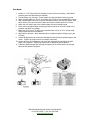
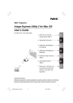
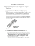
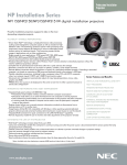
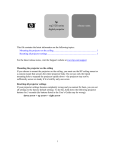
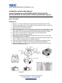
 NEC Display Solutions of America, Inc. Installation and Assembly Manual: Custom Ceiling Mount for NEC NP1000, NP2000, NP1150, NP2150, NP3150, NP3151W, NP1250, NP2250, NP3250, and NP3250W Projectors Model: NP3150CM Ceiling Mount
1. Remove ¼”-20 button head bolt on ceiling plate to remove lower portion of mount.
2. Install the ceiling plate with (4) 5/16” bolts to structural attachment points. Lag screws
may be used when attaching to wood joists.
3. Reattach the lower portion of the mount.
4. Attach interface plate (pn 72-061) to projector with (4) M4 x 10 pan head Phillips screws.
5. Align interface plate into holes on mount, slide stand off bolts into slots and tighten. Add
center locking Torx cap screw which attach secures the interface plate to the mount.
6. Attach the wire safety rope to the interface plate with the enclosed coupler.
7. Attach power and signal cables to projector.
8. Attach the I/O cover (pn 72-065) to the interface plate with (4) 10-32 x 3/8 pan head
Phillips screws and #10 lock washers.
9. Loosen tilt adjustment cap screw with enclosed tool and level the projected image to the
screen. Tighten cap screw when a level image is achieved.
10. Loosen up-down pitch adjustment cap screw with enclosed tool and adjust the pitch
angle of the projector. Tighten cap screw when at desired projection position.
11. If desired, add Kensington lock through the opening of the mount head, loop through
cable end and attach to projector.
5880 Sheridan Boulevard, Arvada, Colorado 80003
Ph: 303-412-0399 ▪ Fax: 303-412-9346
www.displaydevices.com
Pole Mount
1. Install a 1 ½” NPT pipe with male threads on lower end from the ceiling. Aftermarket
mounting pans and accessories are available.
2. Thread locking ring onto pipe. Thread mount onto pipe and leave locking ring loose.
3. Attach interface plate (pn 72-061) to projector with (4) M4 x 10 pan head Phillips screws.
4. Align interface plate into holes on mount, slide stand off bolts into slot and tighten. Add
center locking Torx cap screw which attach secures the interface plate to the mount.
5. Attach the wire safety rope to the interface plate with the enclosed coupler.
6. Insert power and signal cables through pipe and out the top of the mount head to the
projector and attach to projector.
7. Attach the I/O cover (pn 72-065) to the interface plate with (4) 10-32 x 3/8 pan head
Phillips screws and #10 lock washers.
8. Adjust left-to-right yaw. When desired position is attained, tighten locking ring on pipe
to mount.
9. Loosen tilt adjustment cap screw with enclosed tool and level the projected image to the
screen. Tighten cap screw when a level image is achieved.
10. Loosen up-down pitch adjustment cap screw with enclosed tool and adjust the pitch
angle of the projector. Tighten cap screw when at desired projection position.
11. If desired, add Kensington lock through the opening of the mount head, loop through
cable end and attach to projector.
5880 Sheridan Boulevard, Arvada, Colorado 80003
Ph: 303-412-0399 ▪ Fax: 303-412-9346
www.displaydevices.com