1
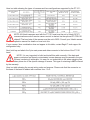
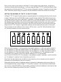
EAGLE
PAN TILT SYSTEMS
Helping to bring your world
into focus
PT-101
Operations and Instructions Manual
Revision 1
12/15/03
Designed and Manufactured by
Eagle Pan Tilt Systems
5880 N. Sheridan Blvd.
Arvada, CO 80003
(303)412-0399
www.eaglepantilt.com
Contents
IMPORTANT SAFETY INSTRUCTIONS ................................................................................................. 3
ITEMS INCLUDED WITH YOUR NEW PT-101 PAN TILT HEAD: .............................................................. 6
UNPACKING AND INSTALLING THE PT-101 PAN TILT HEAD ................................................................. 6
SETTING THE ADDRESS OF THE PT-101 PAN TILT HEAD .................................................................... 9
RS-485 CONNECTION AND TERMINATION ....................................................................................... 10
RS-232 SERIAL OPERATION ............................................................................................................ 10
ENERGIZING THE SYSTEM .............................................................................................................. 11
PAN-TILT OPERATIONS ................................................................................................................... 11
EAGLE™ PT-PS Series Pan Tilt Head—Power Supplies Installation and Operations Manual .................... 14
PRECAUTIONARY STATEMENT ........................................................................................................ 14
WARRANTY ................................................................................................................................... 14
HARDWARE INSTALLATION ............................................................................................................ 14
POWER REQUIREMENTS AND PIN CONFIGURATIONS ....................................................................... 14
FREQUENTLY ASKED QUESTIONS / SETUP PROBLEMS...................................................................... 16
Declaration of Conformity ................................................................................................. 18
PRECAUTIONARY STATEMENT AND
WARRANTY
Please read all of the following documentation before attempting the installation and configuration of these systems. If any of the instructions are unclear to you, call
your servicing dealer or Hitachi before proceeding for clarification. Failure to correctly
configure and install these systems may cause damage to the equipment, and will void the
warranties. Please make sure before connecting or disconnecting any cables that the
power supplies are turned OFF.
WARRANTY
Hitachi Denshi America, Ltd. warrants to the original customer that each PT-101 unit shall
be free from malfunction due to defective workmanship or component failure for a period of TWO
YEARS from the original date of delivery to the customer. For service under the warranty period,
return authorization must be obtained before returning the product. This warranty does not apply
to finish or appearance items, to malfunction due to abuse, or operation in violation of published
operating specifications, or to failures caused by improper installation, connections, modifications,
alterations, or other unauthorized repairs. This warranty does not cover labor or shipping costs for
removal and/or reinstallation of equipment under warranty. Under no circumstances shall Hitachi
Denshi America, Ltd. or Display Devices, Inc., their owners or employees be liable to you for any
special damages, including any lost profits, lost savings, or other incidental or consequential
damages, or for any claim by any other party.
IMPORTANT SAFETY INSTRUCTIONS
1. Read ALL The Instructions! All the safety and operating instructions should be read before the
product is operated
2. Retain Instructions. These safety and operating instructions should be retained for future reference.
3. Heed Warnings. All warnings on the product and the operating instructions should be adhered
to.
4. Follow Instructions. All operating and use instructions should be followed.
5. Cleaning. Unplug this product from the power supply before cleaning. Do not use liquid cleaners
or aerosol cleaners. Use only a damp cloth for cleaning.
6. Attachments. Do no use attachments not recommended by the product manufacturer as they
may cause hazards.
7. Water and Moisture. Do not use this product near water--for example, near a bath tub, wash
bowl, kitchen sink, or laundry tub, wet basement, swimming pool, pond, or similar areas.
8. Accessories. Do not place this product on an unstable cart, stand, tripod, bracket, or table. The
product may fall, causing serious injury to a child or adult, and cause serious damage to the product. Use only with a cart, stand, tripod, bracket, or table recommended by the manufacturer, or
sold with the product. Any mounting of the product should follow the manufacturers’ instructions,
and should use only mounting accessories recommended by the manufacturer.
9. Moving. A product and cart combination should be moved with care. Quick stops, excessive
force, and uneven surfaces may coarse the product and cart combination to overturn.
10. Ventilation. The outer case of the unit functions as a heat sink for the electronics contained
inside. Do not block off the product from airflow by placing the product on a bed, sofa, rug, or
similar surface. This product should not be placed in a built-in installation such as a bookcase or
rack unless proper ventilation is provided or the manufacturers’ instructions have been adhered to
.
11. Power Sources. This product should be operated only from the type of power source indicated
on the marking label. If you are not sure of the type of power supply to your facility, consult your
product dealer or local power company.
12. Grounding or Polarization. This product’s power supply is supplied with a three wire grounding
type plug; a plug having a third (grounding) pin. This is a safety feature. If you are unable to insert
the plug into the outlet, contact an electrician to replace the obsolete outlet. Do not defeat the
purpose of the grounding plug.
13. Power cord protection. Power supply cords should be routed such that they are not likely to be
walked on or pinched by items placed upon or against them, paying particular attention to the
cords at plug, receptacle, and to the point at which they enter the power supply and the product.
14. Lightning. For added protection for this product during a lightning storm, or when it is left
unattended and unused for long periods of time, unplug it from the wall outlet. This will prevent
damage to the product due to lightning and power line surges.
15. Overloading. Do not overload wall outlets, extension cords, or receptacles as this can result in
a risk of fire or electric shock.
16. Object and liquid entry. Never push objects of any kind into this product through openings as
they may touch voltage points or short out parts that could result in a fire or electrical shock. Never
spill liquid of any kind on the product.
17. Flammable and Explosive substances. Avoid using this product where there are gases and
also where there are flammable and explosive substances in the immediate vicinity.
18. Heavy shock or vibration. When carrying this product around, do not subject the product to
heavy shock or vibration.
19. Servicing. Do not attempt to service this product yourself as opening or removing covers may
expose you to dangerous voltage or other hazards. Refer all servicing to qualified service personnel.
20. Damage requiring service. Unplug this product from the wall outlet and refer servicing to qualified service personnel under the following conditions: a--When the power supply cord or plug is
damaged. b--if liquid has been spilled, or objects have fallen into the product. c--If the product has
been exposed to rain or water. d-- if the product does not operate normally by following the operat-
ing instructions. Adjust only those controls which are covered by the operating instructions as
improper adjustment of other controls may result in damage and will often require extensive work
by a qualified technician to restore the product to its normal operating range. e-- if the product has
been dropped or damaged in any way. f--When the product exhibits a distinct change in performance, this indicates a need for service.
21. Replacement parts. When replacement parts are required, be sure that the service technician
has used replacement parts specified by the manufacturer or have the same characteristics as the
original part. Unauthorized substitutions may result in fire, electric shock, or other hazards.
22. Safety Check. Upon completion of any service or repairs to this product, ask the service technician to perform safety checks to determine that the product is in proper operating condition.
23. Wall or Ceiling mounting. This product should only be mounted to a wall or ceiling using brackets made and/or as specified by the manufacturer.
24. Heat. The product must be situated away from heat sources such as radiators, heat registers,
stoves, or other products (including amplifiers or direct sunlight) that produce heat.
ITEMS INCLUDED WITH YOUR NEW PT-101 PAN TILT HEAD:
PT-101 PAN TILT HEAD
ADJUSTABLE CAMERA BRACKET
2x 1/4”-20 x 3/8” BUTTON HEAD HEX CAMERA MOUNTING SCREWS
5 PIN POWER/DATA INPUT CONNECTOR PACK
CAMERA POWER AND CONTROL CABLE
OPTIONAL: INCLUDED WITH PT-101 COMP IS A 15 PIN LOOP THRU CABLE FOR COMPONENT-Y/C SIGNAL AND POWER CONNECTION
UNPACKING AND INSTALLING THE PT-101 PAN TILT HEAD
Included with this package is a graphical flow chart showing images of the correct manner of
installation. Use it in conjunction with these written instructions to complete the installation of the
PT-101 system.
Remove the PT-101 head, camera bracket and accessories from the protective foam packaging. It
is recommended to save this packaging until the installation is complete and the head has been
put into operation, in the unlikely event that there is a problem and it needs to be returned for
service.
Choose either the wall/table mounting configuration, or optional ceiling mount configuration. If
utilizing the optional PT-WM-L wall mount, make sure that the wall can support a weight of at least
45 lbs. (or 2.5 times the max. weight of the PT-101 head, camera, lens, and bracket)
If using the optional PT-CM-101 ceiling mount adapter, install the adapter on the base of the head
now using the accessory kit supplied with the adapter. Make certain that the ceiling structure can
support a weight of at least 45 lbs. (or 2.5 times the max.weight of the PT-101 head, camera, lens,
and bracket).
Attach the angle mount camera bracket to the tilt mounting disc on the side of the head. Keep in
mind that if you are ceiling mounting (inverting) the head, the angle bracket must be inverted as
well. (see photo)
Take the camera / lens assembly, place it on a desktop or other flat surface, with a pen or pencil
underneath the assembly. Carefully roll the assembly forward and back until the balance point is
found. Using the photos as a guide, loosely attach the camera/lens to the angle bracket using the
1/4-20 x 3/8” button head hex fasteners.
NOTE: It is very important to make certain the center points of the camera/lens and the
tilt disc are coincident. If they are not, the front / rear balance will be off, and the pan tilt
head may suffer performance degradation to the point of not working. Please make sure
to check the front/rear balance before calling for service.
When centered, tighten the 1/4-20 screws firmly to secure the assembly.
Attach the pre-built supplied cable harness from the rear of the pan tilt to the rear of the camera.
Note that the proper connectors are supplied for your particular camera model for power and
control ports. Attach the lens control cable from your lens to the connector on the rear of the pan
tilt head. If you are using a C mount lens with auto iris, and your camera supports auto iris operation, attach the four pin link from your camera body to the four pin connector on the lens body.
If using the optional 15 pin pass thru cable for component, RGB, or Y/C signal output, attach it
between the camera body and the 15 pin socket on the rear of the PT-101 head. You must supply
your own breakout cable to attach to the 15 pin connector on the base of the pan tilt head, or buy
a specially made one direct from Hitachi. Several configurations of cable are available depending
upon your needs.If making your own cable, the pin outs are shown in a diagram in the Hitachi
camera manual.
Here is a table showing the types of cameras and lens configurations supported by the PT-101 :
NOTE: All Hitachi cameras used with the PT-101 head must be set to Hitachi RC-Z3
communications mode if remote camera control is desired via the optional PT-CCB-101
chipset!! The baud rate of the camera must be set to 9600. Consult your Hitachi camera
operation manual for details on how to do this.
If your camera / lens combination does not appear in this table, contact Eagle™ tech support for
configuration help.
Next, build up and attach the 5 pin main power and data connector to the bottom of the PT-101
head.
NOTE: It is very important to build and install this cable correctly; if the data and
power conductors are flipped or misoriented, severe damage may be caused to the pan
tilt head, rendering it inoperable. It is easy for our technicians to tell when miswiring has
taken place due to the specific damage it causes. This type of miswiring is NOT covered
by the warranty.
Here is a table showing the correct wiring order and purpose. Please note that the connector on
the base of the head is labeled with numbers from 1 to 5:
Now you may hook up the wiring to the Eagle™ control system and power supply, using the instructions included with those devices. If you are using the Eagle™ PT-T2 connection block, follow
the instructions included with the PT-T2 for system configuration choices. Proceed to the next step
ONLY when the system wiring is complete, and all connections have been verified for accuracy.
SETTING THE ADDRESS OF THE PT-101 PAN TILT HEAD
All Eagle™ PT-101 pan tilt heads require a separate address for controlling them by serial communication. Each pan tilt on the RS-485 line has a specific logical address.This address may be set
by software control from one of the Eagle™ controllers or software packages, or set mechanically
via the dip switches located under the removable top access panel on the PT-101 head. To access
the address setting switches, remove the six hex head screws securing the cover (two each on
right and left sides, one each front and back. With the cover removed, you will see the main logic
board for the PT-101. A bank of eight white switches can be found near the center of the board.
The convention for the switches is this: down is OFF(or zero), up is ON. With all switches down/
off, the head’s address is set by remote control.
With only switch number 1 in the up position, the head’s address is 1. With only switch number 2
up, the address is 2. With only switch number 3 up, the address is 4. With only switch number 4
up, the address is 8. With only switch number 5 up, the address is 16. With only switch number 6
up, the address is 32. With only switch number 7 up, the address is 64. The switches may be
configured in any manner to arrive at a desired address up to 127 (all switches
up=1+2+4+8+16+32+64=127) For example, to set address number 3, switches 1 and 2 should be
up. For address 6, switches 2 and 3 should be up (2+4=6).
Note that if the dip switches are set with the unit powered up, the unit power must be cycled off
and back on for the address to be set in memory.
Remember that this method of address setting is optional, as addresses can be more easily set
and changed remotely using an Eagle™ PT controller. However, in the event that multiple heads
are used on a single RS-485 line, this provides a method of setting the address in the head so that
they cannot be changed by accident from the PT controller.
To set the address by remote control from a PT controller or software, follow this procedure. The
address is set by the factory to 1 when shipped. If a change is required, follow the procedure for
your particular model of Eagle™ controller:
PT-C-50 controller: Enter FUNCT, PRESET 4, then select PRESET 1 through 8 to set addresses
from 1 through 8. Note that the PT-C-50 controller is limited to control of 8 PT heads.
PT-C controller: simply enter FUNCTION, the 11 button; the LCD display will read ADDRESS.
Then push the number you wish to set the head to.
PT-TSC touchscreen controller: From the main page, touch the FUNCTION button. Then touch the
SET PT ADDRESS button. On the numeric keypad that pops up, touch the number you wish the
head to become, followed by the ENTER button.
Note that the remote addressing procedure will only work if you know the number the head is
currently set to; if you don’t know the number, first select CAMERA, ALL. This will allow you to talk
to any head that is correctly wired up and powered.
Note that this will set the number for all heads on the RS-485 comm line; you must
disconnect the power or communication for all the heads except the one you wish to
address, otherwise all the powered and connected heads will be set to the same address.
RS-485 CONNECTION AND TERMINATION
Communications for the PT-101 is transmitted via the RS-485 standard, a common
multidrop network configuration. Three wires are required for RS-485 communications, two for
signal and one for ground. Using 20 AWG shielded twisted pair cable, maximum communication
length without a repeater is 4,000 feet.
To connect multiple units to the same communication line, you may connect the three wires
in parallel from unit to unit; or in a star configuration from a PT-T2 hub out to each head. On each
of the pan tilt heads and in the controller is a 120 ohm terminating resistor. The resistor is connected in series to a switch for easy configuration; this switch for termination is located on the side
of the unit (under the removeable top access panel) next to a COMM status LED; with the switch
towards the LED, the head is terminated; with the switch away from the LED, the head is
unterminated. Heads are shipped with the termination turned ON. The easiest way to terminate
your system is to terminate the head that is farthest away by cable distance, and leave the controller terminated. Any other head should NOT be terminated.
If using a controller other than the Eagle™ pan tilt controller, such as an AMX or Crestron control
system, termination should be provided at the card cage end.
RS-232 SERIAL OPERATION
The PT-101 pan tilt head is capable of direct RS-232 operation right out of the box. No adapters
are needed. Under the top cover access panel you will find three black repositionable jumpers.
The PT-101 is shipped in standard RS-485 mode; with all of the jumpers UP.
Switch all three of the jumpers to the lower position, and the head is now configured for RS-232
mode. The same control codes used for RS-485 apply for moving the head using Eagle™ software or when writing your own software. These control codes are available off of the Eagle
website, http://www.eaglepantilt.com. Please be aware that the maximum reliable distance for RS232 control is only about 50 to 75 feet, and that only one PT-101 head may be hooked up per
serial port as is standard with RS-232 communications.
ENERGIZING THE SYSTEM
Power up the Eagle™ pan tilt controller before powering up the PT-101 pan tilt head. When this is
done, you may now power up the power supply for the PT-101 head(s). Observe the red status
LED lens on the front of the pan tilt head. About two seconds after power is applied, the LED
should blink twice. This is to signal that the main microprocessor is active, and ready to receive a
command. The head will automatically travel to it’s “home” position of straight ahead and level.
During this travel period, remote control is not possible. This home position is not able to be
changed, and the head must home itself whenever power is applied. If the head does not go to the
home position, it will not function; please call for service.
The LED provides important visual feedback to the status of the head; if the head has been activated and is being talked to by a controller, the LED is on solid, with some flickering. If the head is
attached to the RS-485 line and hearing a command being sent to another head, it will flicker.
If the LED comes on solid, with no flickering at all, it usually means the RS-485 wiring is incorrect.
Usually the ground and one of the data lines have been swapped. Check the wiring and try again.
PAN-TILT OPERATIONS
Be sure to follow all of the installation and safety instructions included with the Eagle™ PT101 pan tilt head before starting to use this system !!
First, select the address of the head you wish to control. Since up to 31 Eagle™ heads may be on
a single RS-485 line, you must choose the correct one to control (only 8 may be controlled from
the PT-C-50 controller). Select CAMERA, then the number of the head to be controlled. Head
addresses can be changed as described in the previous section about addressing on page 9.
If this is the first use of the system, the limits of pan tilt movement should be adjusted as desired
now. Begin by entering the proper command on your controller to clear all movement limits. This
function will eliminate all safety limits that have been set at the factory to prevent excess travel.
This clearing is temporary only; when power is cycled off and on, the previous limits will return
unless you have set new limits. This will erase any limits previously set by the factory during testing.
Now, set the safety limits of travel as desired. Use the LIMIT then UP, DOWN, RIGHT, and LEFT
for up, down, left, and right limit setting. Remember, that the pan tilt head has a range of pan of
360° (left or right 180°), and a tilt range of 180° (up or down 90°); it cannot turn more than a full
circle. There are end travel stops programmed into the head at the factory to prevent traveling
more than these amounts; these cannot be cleared when clearing the safety limits. Once the travel
limits are set, normal usage of the pan tilt system may begin.
The PT-101 head uses DC stepper type motors instead of geared motors. If an obstruction is
encountered during travel, the motor merely “slips” until the condition is corrected. This prevents
damage to both the pan tilt head and the camera/lens. If this occurs, recalled preset positions will
not be recalled correctly until the next time the PT-101 head passes through the “home” position
of straight ahead and level.
EAGLE™ PT-PS Series Pan Tilt Head—Power Supplies Installation and Operations Manual
PRECAUTIONARY STATEMENT
Improper settings and connections may cause damage to the PT-101 pan tilt, the camera, and the lens being used. Please read all of the following documentation before
attempting the installation and configuration of these systems. If any of the instructions
are unclear to you, call your servicing dealer or Hitachi before proceeding for clarification. Failure to correctly configure and install these systems may cause damage to the equipment,
and will void the warranties. Please make sure before connecting or disconnecting any cables that
the power supplies are turned OFF.
WARRANTY
Hitachi Denshi America, Ltd. warrants to the original customer that each unit shall be free
from malfunction due to defective workmanship or component failure for a period of ONE YEAR
from the original date of delivery to the customer. For service under the warranty period, return
authorization must be obtained before returning the product. This warranty does not apply to finish
or appearance items, to malfunction due to abuse or operation in violation of published operating
specifications, or to failures caused by improper connections, modifications, alterations, or other
unauthorized repairs. This warranty does not cover labor costs for removal and/or reinstallation of
equipment under warranty, nor does it include shipping costs. Under no circumstances shall
Hitachi Denshi America, Ltd. or Display Devices, Inc., their owners or employees be liable to you
for any special damages, including any lost profits, lost savings, or other incidental or consequential damages, or for any claim by any other party.
HARDWARE INSTALLATION
Before starting installation, make certain that all power supplies to equipment are turned OFF.
POWER REQUIREMENTS AND PIN CONFIGURATIONS
The PT-PS power supplies are designed to provide reliable power to the Eagle pan tilt heads. The
PT-PS-1 will provide power for one PT-50 head and camera assembly; the PT-PS-2 will provide
enough power for up to four PT-50 head and camera combinations and the PT-PS-3 provides 6.5
amps, for use with PT-200/300 heads and larger cameras. The Eagle™ pan tilt heads require 24
volts DC power. Maximum draw is approximately 2.5 amps; average current draw in operation is
1.5 amps. The camera power supply built into every PT head will provide power for camera / lens
combinations drawing up to 3 amps at 12 VDC; if the camera / lens draws more than this, a separate external camera power supply is required. To help reduce power drop, it is common practice
to run 4 conductors for power and tie two conductors together at the end entering the pantilt head,
thus doubling the effective current carrying capability.
Here is a chart with recommended AWG for different distances ( at 77°F )
Here is the listing of pin configurations for the connector on the power supply output:
AMP 4 pin CPC connector
PIN 1 +24 VDC CAMERA POWER SUPPLY TO HEAD
PIN 2 +24 VDC CAMERA POWER SUPPLY TO HEAD
PIN 3 CAMERA POWER SUPPLY GROUND TO HEAD
PIN 4 CAMERA POWER SUPPLY GROUND TO HEAD
IMPORTANT NOTE: THE PT-PS-* POWER SUPPLIES ARE AUTOSWITCHING FOR INPUT VOLTAGE RANGES
BETWEEN 100 AND 240 VAC, 50 OR 60 HERTZ.
FREQUENTLY ASKED QUESTIONS / SETUP PROBLEMS
My pan tilt head was working, but now has stopped responding. I still have a picture from
the camera, but have no control. What happened?
A: You are either trying to control the wrong head number, or the head has accidentally been
readdressed to an another number, or the serial communications have failed. If you are certain
that you are trying to control the correct head, follow this procedure to regain control.
1. On the PT controller, enter the appropriate command to select CAMERA,-ALL. This will talk to
any head on the line. Try to move the head up, down, left, or right. If it responds, then you have
good communications. Follow the procedure on page 8 to readdress the head to the number you
want it to be.
2) If it doesn’t respond, then check the serial wiring path from the controller to the head(s). If you
have multiple heads, and the other heads work correctly, then your wiring path is most likely correct, but should still be tested. Try moving the non-working head to a known working location and
retesting.
3) The red LED on the front panel of the head is for troubleshooting and status. If a head is correctly wired and addressed, when you move the joystick, the LED will glow solid, with some
modulation(flickering) seen as you move the joystick. If the LED comes on solid upon power up,
then the RS-485 ground and one of the comm lines are reversed. Check your wiring again. If the
LED never comes on solid, but only flickers, then either the head is hearing traffic for another
head, or the RS-485 A & B comm lines are reversed. If you are certain the head is addressed
properly, then swap the A&B comm lines and test again.
If it still doesn’t work at a known good location, you have swapped the comm lines, and tried
readdressing, then the head may be faulty. Contact Eagle tech support at (303) 412-0399 or
www.eaglepantilt.com.
My lens control isn’t working correctly; the lens goes to one end of its’ range and wont
move.
The lens type has been set incorrectly. The Eagle pan tilt system is capable of using either servo
drive teleconferencing lenses, or DC drive C-mount lenses. If set to the wrong type, this symptom
will result. Verify the type of lens you are using and check the lens type as shown on page 7.
I am trying to set up a preset shot, but the head isn’t returning to the correct position or
zoom/focus setting.
This could be caused by a number of things. First, if using a teleconferencing lens, make sure you
are going into POSITION mode before trying to set the preset. If you are not in POSITION mode,
the lens’ zoom and focus settings cannot be memorized.
If the zoom and focus settings are retrieved correctly, but the head is landing too high or low when
recalling, then the weight balance of the camera/lens assembly is probably off from front to rear.
The assembly must be centered from front to rear to provide accurate recall; if it is balanced too
far front, then it will probably be low in recalling presets above horizontal. If balanced too far rear, it
will be high in recalling presets above horizontal. Remove the camera/lens assembly as needed in
order to check the balance, and replace it in the correct position.
IF YOU ARE EXPERIENCING A PROBLEM NOT COVERED HERE, OR YOU HAVE TROUBLE
UNDERSTANDING THESE SOLUTIONS, PLEASE CONTACT TECH SUPPORT AT (303) 4120399, M-F 8AM TO 5PM US MOUNTAIN TIME ZONE, OR EMAIL [email protected].
Declaration of Conformity
We, Display Devices Inc., of the United States, confirm that the following products are in conformity with the essential requirements of EC Directive(s)
73/23/EEC, 89/336/EEC, and 93/68/EEC by applying the following standards
EN60950, EN50081-1(EN55022 Class B) and EN50082-1
A)
the use of shielded cable is required to comply with limits specified by above standards
B)
Use of ferrite core is required to comply with limits specified by above standards.
Eagle PT-50, PT-101 pan tilt heads, Eagle PT-C, Eagle PT-CC, PTC50 controllers, and Eagle PTPS-* power supplies
These products are in conformity with the EMC directive at nominal mains input 230V, 50Hz even
though the rated input of the products is 90VAC to 240VAC, 50 or 60 Hz