1
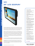
AUTO-SCANNING WITH DIGITAL CONTROL
LCD COLOR DISPLAY MONITOR
MultiSync® LCD1800™
USER’S GUIDE
SIGNAL A/B
SELECT
ADJUST
-
+
OSD OFF
For future reference, record the serial
number of your display monitor in the
space below:
SERIAL No.
The serial number is located on the
rear cover of the monitor.
Internet Home Page: http://www.necmitsubishi.com/
Supplying Windows 95/98 INF File download service,new products
information, etc.
As an ENERGY STAR Partner, NEC-MITSUBISHI
Electronics Display of America, Inc. has determined
that this product meets the ENERGY STAR guidelines for energy efficiency.
RADIO INTERFERENCE REGULATIONS STATEMENT FOR U.S.A.
This equipment has been tested and found to comply
with the limits for a Class B digital device, pursuant to
Part 15 of the FCC Rules. These limits are designed to
provide reasonable protection against harmful interference in a residential installation. This equipment generates, uses and can radiate radio frequency energy
and, if not installed and used in accordance with the
instructions, may cause harmful interference to radio
communications. However, there is no guarantee that
interference will not occur in a particular installation. If
this equipment does cause harmful interference to
radio or television reception, which can be determined
by turning the equipment off and on, the user is encouraged to try to correct the interference by one or more of
the following measures:
-
-
Reorient or relocate the receiving antenna.
Increase the separation between the equipment
and receiver.
Connect the equipment into an outlet on a circuit
different from that to which the receiver is connected.
Consult the dealer or an experienced radio/TV technician for help.
NO USER SERVICEABLE PARTS INSIDE. DO NOT ATTEMPT TO MODIFY
THIS EQUIPMENT. IF MODIFIED, YOUR
AUTHORITY TO OPERATE THIS EQUIPMENT MIGHT BE VOIDED BY FCC.
Declaration of Conformity - United States only
Product Name:
Type:
Brand Name:
18.1 in. (46cm) Color Display
Monitor
LSA831W
NEC
This device complies with Part 15 of the FCC Rules.
Operation is subject to the following two conditions:
(1) this device may not cause harmful interference, and
(2) this device must accept any interference received,
including interference that may cause undesired operation.
For questions regarding this declaration, contact:
NEC-Mitsubishi Electronics Display of
America, Inc.
1250 N. Arlington Heights Road,
Suite 500 Itasca, IL 60143
or, call 630-467-5000
To identify this product, refer to the model number found
on the product.
- III -
Below you will find a brief summary of the environmental
requirements met by this product. The complete
environmental criteria document may be ordered from:
Congratulations!
You have just purchased a TCO’99 approved and labelled
product! Your choice has provided you with a product
developed for professional use. Your purchase has also
contributed to reducing the burden on the environment and
also to the further development of environmentally adapted
electronics products.
Why do we have environmentally labelled computers?
In many countries, environmental labelling has become an
established method for encouraging the adaptation of
goods and services to the environment. The main problem,
as far as computers and other electronics equipment are
concerned, is that environmentally harmful substances
are used both in the products and during their manufacture.
Since it is not so far possible to satisfactorily recycle the
majority of electronics equipment, most of these potentially
damaging substances sooner or later enter nature.
There are also other characteristics of a computer, such as
energy consumption levels, that are important from the
viewpoints of both the work (internal) and natural (external)
environments. Since all methods of electricity generation
have a negative effect on the environment (e.g. acidic and
climate-influencing emissions, radioactive waste), it is vital
to save energy. Electronics equipment in offices is often
left running continuously and thereby consumes a lot of
energy.
What does labelling involve?
This product meets the requirements for the TCO’99 scheme
which provides for international and environmental labelling
of personal computers. The labelling scheme was
developed as a joint effort by the TCO (The Swedish
Confederation of Professional Employees), Svenska
Naturskyddsforeningen (The Swedish Society for Nature
Conservation) and Statens Energimyndighet (The Swedish
National Energy Administration).
Approval requirements cover a wide range of issues:
environment, ergonomics, usability, emission of electric
and magnetic fields, energy consumption and electrical
and fire safety.
The environmental demands impose restrictions on the
presence and use of heavy metals, brominated and
chlorinated flame retardants, CFCs (freons) and chlorinated
solvents, among other things. The product must be prepared
for recycling and the manufacturer is obliged to have an
environmental policy which must be adhered to in each
country where the company implements its operational
policy.
The energy requirements include a demand that the
computer and/or display, after a certain period of inactivity,
shall reduce its power consumption to a lower level in one
or more stages. The length of time to reactivate the
computer shall be reasonable for the user.
Labelled products must meet strict environmental demands,
for example, in respect of the reduction of electric and
magnetic fields, physical and visual ergonomics and good
usability.
- IV -
TCO Development
SE-114 94 Stockholm, Sweden
Fax: +46 8 782 92 07
Email (Internet): [email protected]
Current information regarding TCO’99 approved and
labelled products may also be
obtained via the Internet, using the address:
http://www.tco-info.com/
Environmental requirements
Flame retardants
Flame retardants are present in printed circuit boards,
cables, wires, casings and housings. Their purpose is to
prevent, or at least to delay the spread of fire. Up to 30%
of the plastic in a computer casing can consist of flame
retardant substances. Most flame retardants contain
bromine or chloride, and those flame retardants are
chemically related to another group of environmental toxins,
PCBs. Both the flame retardants containing bromine or
chloride and the PCBs are suspected of giving rise to
severe health effects, including reproductive damage in
fish-eating birds and mammals, due to the bio-accumulative*
processes. Flame retardants have been found in human
blood and researchers fear that disturbances in foetus
development may occur.
The relevant TCO’99 demand requires that plastic
components weighing more than 25 grams must not contain
flame retardants with organically bound bromine or chlorine.
Flame retardants are allowed in the printed circuit boards
since no substitutes are available.
Cadmium* *
Cadmium is present in rechargeable batteries and in the
colour-generating layers of certain computer displays.
Cadmium damages the nervous system and is toxic in high
doses. The relevant TCO’99 requirement states that
batteries, the colour-generating layers of display screens
and the electrical or electronics components must not
contain any cadmium.
Mercury* *
Mercury is sometimes found in batteries, relays and
switches. It damages the nervous system and is toxic in
high doses. The relevant TCO’99 requirement states that
batteries may not contain any mercury. It also demands
that mercury is not present in any of the electrical or
electronics components associated with the labelled unit.
CFCs (freons)
The relevant TCO’99 requirement states that neither CFCs
nor HCFCs may be used during the manufacture and
assembly of the product. CFCs (freons) are sometimes
used for washing printed circuit boards. CFCs break down
ozone and thereby damage the ozone layer in the
stratosphere, causing increased reception on earth of
ultraviolet light with e.g. increased risks of skin cancer
(malignant melanoma) as a consequence.
Lead* *
Lead can be found in picture tubes, display screens,
solders and capacitors. Lead damages the nervous system
and in higher doses, causes lead poisoning. The relevant
TCO´99 requirement permits the inclusion of lead since no
replacement has yet been developed.
*
**
Bio-accumulative is defined as substances which
accumulate within living organisms
Lead, Cadmium and Mercury are heavy metals which
are Bio-accumulative.
CAUTION
Do not remove the monitor cabinet as this can
expose you to very high voltages and other hazards.
MANUFACTURER DECLARATION FOR
CE-MARKING:
We, NEC-MITSUBISHI ELECTRIC VISUAL SYSTEMS CORPORATION declare under our sole
responsibility, that this product is in conformity with
the following standards:
EN60950
EN55022 Class B
EN50082-1
EN61000-3-3
following the provisions of:
73/23/EEC Low Voltage Directive
89/336/EEC EMC Directive
WARNING!
This product is not designed for use in life support
devices and NEC-MITSUBISHI ELECTRIC VISUAL
SYSTEMS CORPORATION makes no representations to the contrary. Life support devices are those
devices which are used to measure, diagnose, or
evaluate the tissue, systems or functions of the human
body; or other devices employed to support or sustain
life or good health.
1. INTRODUCTION ..................................................
1.1 Features .....................................................
1.2 Internal Preset Memory Capability .............
1.3 IPM™(Intelligent Power Manager) System .
1.4 DDC ...........................................................
1.5 Display Mode Selection .............................
1.6 Auto Adjustment Function ..........................
1.7 Screen Auto Expand Function ...................
1.8 Signal Input Connector
Auto Selection Function .............................
1.9 Auto Brightness Function ...........................
1.10 AccuColor® Control Function .....................
1.11 Location Considerations ............................
1.12 Cleaning Your Monitor ...............................
1.13 Unpacking ..................................................
1.14 Tilt Base .....................................................
Screen Position Adjustment .......................
1.15 Quick Operation Chart ...............................
1-2
1-2
1-2
1-3
1-3
1-3
1-3
1-3
1-3
1-3
1-4
1-4
1-4
1-4
1-4
1-4
1-5
2. PART NAME ........................................................ 1-6
2.1 Control Names ........................................... 1-6
2.2 Function ..................................................... 1-6
3. INSTALLATION AND CONNECTION .................. 1-7
3.1 AC Power Connection ................................ 1-7
3.2 Signal Cable Connection ........................... 1-7
3.2.1 Connecting to Any IBM VGA Compatible
System .................................................. 1-7
3.2.2 Connecting to An Apple Macintosh
Computer .............................................. 1-8
3.2.3 Connecting to Two Computers .............. 1-8
4. AUTO SETUP FUNCTION ................................... 1-9
5. OSM™(On Screen Manager) FUNCTIONS .......... 1-9
5.1 Adjustment Items ....................................... 1-10
5.2 CONTROL LOCK Mode Operation ............ 1-11
6. TROUBLESHOOTING ......................................... 1-12
Trademark
7. SPECIFICATIONS ............................................... 1-13
IBM, PC, PS/2, PS/V, Personal System/2 are registered trademarks of International Business Machines Corp.
LIMITED WARRANTY ............................................... 1-14
Apple Macintosh is a registered trademark of Apple Computer, Inc.
Quadra is a trademark of Apple Computer, Inc.
UNIX is a registered trademark in the United States and other
countries, licensed exclusively through X/Open Company Limited.
ENERGY STAR is a U.S. registered mark.
NEC is registered trademark of NEC Corporation.
All other trademarks or registed trademarks are property of their
respective owners.
© 2000 NEC-MITSUBISHI Electronics Display of America, Inc.
- 1-1 -
ENGLISH
CONTENTS
1
INTRODUCTION
Congratulations on your purchase of the MultiSync
LCD1800™ high resolution color LCD monitor.
This guide tells you how to connect, adjust and care for
your MultiSync LCD1800 monitor. This guide also provides technical specifications and instructions for troubleshooting any basic problems you may experience with
your monitor.
1.1
Features
The MultiSync LCD1800 is a 46cm/18.1", intelligent,
microprocessor-based LCD monitor compatible with most
analog RGB (Red, Green, Blue) display standards.
The monitor provides crisp text and vivid color graphics
with both PC and Macintosh platforms.
Dual Inputs
Offers dual inputs, allowing you to connect the monitor
to two systems. You can easily switch between computers with a touch of a button on the front control
panel.
Reduced Footprint
Provides the ideal solution for environments requiring
superior image quality but with size and weight limitations. The monitor’s small footprint and low weight
allow it to be moved or transported easily from one
location to another.
AccuColor® Control System
Allows you to adjust the colors on your screen and
customize the color accuracy of your monitor to a
variety of standards.
OSM™ (On-Screen Manager) Controls
Allow you to quickly and easily adjust all elements of
your screen image via simple to use on-screen menus.
ErgoDesign® Features
Enhance human ergonomics to improve the working
environment, protect the health of the user and save
money. Examples include OSM controls for quick and
easy image adjustments, tilt/swivel base for preferred
angle of vision, small footprint and compliance with
MPRII guidelines for lower emissions.
Plug and Play
The Microsoft® solution with the Windows® operating
system facilitates setup and installation by allowing
the monitor to send its capabilities (such as screen
size and resolutions supported) directly to your computer, automatically optimizing display performance.
IPM™ (Intelligent Power Manager) System
Provides innovative power-saving methods that allow
the monitor to shift to a lower power consumption level
when on but not in use, saving two-thirds of your
monitor energy costs, reducing emissions and lowering the air conditioning costs of the workplace.
Multiple Frequency Technology
Automatically adjusts monitor to the display card’s
scanning frequency, thus displaying the resolution
required.
- 1-2 -
FullScan™ Capability
Allows you to use the entire screen area in most
resolutions, significantly expanding image size.
VESA Standard Mounting Interface
Allows users to connect their MultiSync monitor to any
VESA standard third party mounting arm or bracket.
Allows for the monitor to be mounted on a wall or an arm
using any third party compliant device.
XtraView®
Allows the user to be able to see the monitor from any
angle (160 degrees). Provides full 160° viewing angles
either up, down, left or right.
1.2
Internal Preset Memory Capability
To minimize adjustment needs, the factory has preset
popular display standards into the monitor, as shown in
Table 1. If any of these display standards are detected, the
picture size and centering are automatically adjusted. All
of the factory presets may be overwritten by adjusting the
user controls. The monitor is capable of automatically
storing up to 7 additional display standards. The new
display information must differ from any of the existing
display standards by at least 1kHz for the horizontal scan
frequency or 1Hz for the vertical scan frequency or the sync
signal polarities must be different.
Table 1. Memory Buffer Factory Presets
Polarity
Resolution
640 x 480
832 x 624
1152 x 870
640 x 350
640 x 480
640 x 480
640 x 480
720 x 400
800 x 600
800 x 600
800 x 600
800 x 600
1024 x 768
1024 x 768
1024 x 768
1024 x 768
1024 x 768
1280 x 1024
1280 x 1024
N.I.
N.I.
N.I.
N.I.
N.I.
N.I.
N.I.
N.I.
N.I.
N.I.
N.I.
N.I.
N.I.
N.I.
N.I.
N.I.
N.I.
N.I.
N.I.
Fh(kHz) Fv (Hz)
35.0
66.7
49.7
74.6
68.7
75.0
31.4
70.0
31.5
59.9
37.5
75.0
43.3
85.0
31.5
70.0
37.9
60.3
48.1
72.2
46.9
75.0
53.7
85.0
48.4
60.0
56.5
70.1
58.1
72.1
60.2
75.0
68.7
85.0
64.0
60.0
80.0
75.0
H
+
+
+
+
+
+
+
+
V
+
+
+
+
+
+
+
+
1.3
IPM™(Intelligent Power Manager) System
When the horizontal sync signal and/or vertical sync signal
is off, after about 10 seconds the monitor is switched to a
power saving mode which reduces the monitor power
consumption to less than 3W. When the monitor is in
power saving mode, the screen is off and the power
indicator will illuminate at amber.
After the signals are restored, picture will be displayed
within about 3 seconds.
Check your computer's manual for setting this function.
1.4
DDC
Auto Adjustment Function ("AUTO ADJUST"
P1-10)
This function is to adjust "CLOCK PHASE" automatically
and periodically (once per 30 min.) against changes of the
signal condition or ambient temperature and to adjust
"CLOCK PHASE", "HORIZONTAL POSITION" and "VERTICAL POSITION" automatically when changing the signal timing.
•
•
•
The monitor includes the DDCTM2B feature, more commonly known as "Plug & Play". DDC(Display Data Channel) is a communication channel over which the monitor
automatically informs the computer about its capabililties
(e.g. each supported resolution with its corresponding
timing).
DDC is routed through previously unused pins of the 15pin VGA connector.
The system will perform "Plug and Play" feature if both,
monitor and computer, implement the DDC protocol.
When a Plug and Play computer starts, it identifies the
monitor and loads the appropriate driver automatically. If
the computer does not have the driver installed, a dialog
box will appear asking where the information can be
found. The latest drivers may be downloaded from the
"Support" section of the NEC-MITSUBISHI Website located at:
http://www.necmitsubishi.com/
When you receive the monitor, "AUTO ADJUST" is set
to "OFF".
When using the monitor with some computers, "AUTO
ADJUST" may function negatively. In that case, set
"AUTO ADJUST" to "OFF".
When "AUTO ADJUST" is set to "ON", you may feel
the screen stopping when using mouse or displaying
an animation. However, it is not a fault condition and
it is caused by the "AUTO ADJUST" working.
1.7
This function is to expand the screen automatically. By a
smoothing function, you can get a clear screen when the
screen is expanded by this function. This function is
available in case that a signal of 1024 dots by 768 lines or
lower is inputted to the monitor.
•
•
•
1.5
Display Mode Selection ("DISPLAY MODE"
P1-10)
1.8
The following two display modes are available. You can
select either mode suitable to your work, on the OSM™
(
P1-10).
•
•
•
With some resolution, even if it meets the condition
above, the screen is not expanded fully to the screen
area.
With some signal type inputted, the screen is not
expanded vertically or horizontally.
With some resolution, the image may be slightly
blurred.
Signal Input Connector Auto Selection Function ("AUTO SELECT"
P1-11)
This function is to select the signal input connector which
is in the active condition automatically. In case that two
computers are connected with the monitor, another computer will be selected automatically when the first selected
computer went into a power saving mode.
Text Mode
The contrast is emphasized more than the accuracy of the
color appearance in this mode. This mode is suitable for
such works that the accuracy of the displayed colors is not
so important, e.g. document making, calculation, database making, etc.
Graphic Mode
The accuracy of the color tone is emphasized in this mode.
This mode is suitable for such works where the accuracy
of the displayed colors is important, e.g. photograph
processing, making of illustration, etc.
Screen Auto Expand Function ("EXPAND"
P1-10)
•
1.9
When you receive the monitor, "AUTO SELECT" is set
to "ON".
Auto Brightness Function ("AUTO BRIGHTNESS"
P1-10)
This function is to adjust the brightness automatically to
the extent of white display area, against dazzle.
When you receive the monitor, "DISPLAY MODE" is
set to "GRAPHIC" mode.
Before selecting "Graphic Mode", perform "AUTO
SETUP". If not, the displayed screen may become too
bright.
Before using "Color Matching", set the "COLOR" to
"NATIVE", "DISPLAY MODE" to "GRAPHIC".
(
P1-10)
- 1-3 -
ENGLISH
The monitor has a IPM(Intelligent Power Manager) System which reduces the power consumption of the monitor
when not in use.
1.6
1.10
AccuColor® Control Function
1.13
Unpacking
The following color modes are available:
1. sRGB: sRGB mode dramatically improves the color
fidelity in the desktop environment by a single standard RGB color space. With this color supported
environment, the operator could easily and confidently communicates color without further color management overhead in the most common situations.
We recommend you set the monitor to "Graphics"
mode. (Unadjustable.)
2. VIDEO: Suitable for motion picture. (Unadjustable.)
3. NATIVE: Original color presented by the LCD panel.
(Unadjustable.)
4. CUSTOM: The following items are adjustable.
COLOR TEMPERATURE: 5000K~9600K
COLOR CONTROL: This function enables independent adjustment of 6 color (Red, Yellow, Green,
Cyan, Blue and Magenta) elements and color
saturation.
COLOR RESET: To restore to the color temperature and color control to the factory preset.
After you unpack the box you should have all of the items
indicated in Figure 1. Save the box and packing materials
in case you ship or transport the monitor.
2
1
-
+
3
4
Figure 1
1.11
Location Considerations
When setting up and using the monitor, keep the following
in mind:
•
•
•
•
•
•
For optimum viewing, avoid placing the monitor against
a bright background or where sunlight or other light
sources may reflect on the display area of the monitor;
place the monitor just below eye level.
Avoid covering the slots or openings of the monitor.
Allow adequate ventilation around the monitor so the
heat from the monitor can properly dissipate. Avoid
putting the monitor into any enclosure that does not
have adequate ventilation.
Avoid exposing the monitor to rain, excessive moisture, or dust, as this can cause a fire or shock hazard.
Avoid placing the monitor, or any other heavy object,
on the power cord. Damage to the power cord can
cause a fire or electrical shock.
When transporting the monitor, handle it with care.
Avoid giving any shock or scratch to the screen, as the
screen is fragile.
1.12
1. Multisync® LCD1800™ Monitor
2. Power Cord
3. AC-Adapter
4. User’s Guide (this booklet)
1.14
Tilt Base
The monitor comes with a tilt base. This enables you to
position the monitor to the best angle for maximum viewing
comfort.
Screen Position Adjustment
Adjust the tilt of the monitor by placing your hands at
opposite sides of the case. You can adjust the monitor as
shown in Figure 2.
Cleaning Your Monitor
When clean the monitor, please follow these guidelines:
•
•
•
Always unplug the monitor before cleaning.
Wipe the screen and cabinet front and sides with a soft
cloth.
Do not spray directly on the screen as excess cleaner
may drip into the monitor causing a damage.
-
Do not use benzene, thinner or any volatile substances to
clean the unit as the finish may be permanently marked.
Never leave the monitor in contact with rubber or vinyl for
an extended time period.e the monitor in contact with
rubber or vinyl for an extended time period.
- 1-4 -
+
Figure 2
CAUTION
Keep your fingers away from the pivot area of the tilt/swivel
base.
1.15
Quick Operation Chart
ENGLISH
To summarize the steps in connecting your computer and
adapter with MultiSync LCD1800™ color LCD monitor and
setting the necessary controls and switches, refer to the
chart below.
Connect the power cord to the MultiSync LCD1800
color LCD monitor and the signal cable between
the MultiSync LCD1800 and the computer.
Turn on the monitor.
Turn on the computer.
Set the controls and switches.
If a problem appears.
OK
OK
See 6. TROUBLESHOOTING
If the problem persists.
Call for your authorized Product
Support.
-
+
- 1-5 -
2
PART NAME
2.1
Control Names
See Figures 3 and 4 for the location of the user controls,
indicator and connectors.
Each part is identified by number and described
individually.
REAR
FRONT
-
SIGNAL A/B
+
SELECT
ADJUST
-
+
Figure 4
OSD OFF
Figure 3
2.2
Function
POWER SWITCH: A push-on / push-off switch for
power input.
POWER-ON INDICATOR: This indicator illuminates when power is on.
SIGNAL A/B and OSD OFF BUTTON: This button
has two functions, as follows.
Under the OSM off condition: Push to select the
signal input connector which is connected to the
computer which you want to use.
Under the OSM on condition: Push to turn off OSM.
FUNCTION SELECT BUTTONS: Push the select
buttons to choose one of the functions that is
superimposed on the display screen.
FUNCTION ADJUST BUTTONS: Push the adjust
buttons to adjust the image on the screen that is
selected via the function select buttons.
- 1-6 -
CABLE COVER (UPPER)
CABLE COVER (LOWER)
DC POWER CONNECTOR
SIGNAL INPUT CONNECTOR (SIGNAL B)
BURGLARPROOF KEY LOCK HOLE: available
for KENSINGTON® MicroSaver Security System.
SIGNAL CABLE (SIGNAL A)
CONNECTION
On the back of the monitor are three plug-in connections: one for the DC power connection and others for
the video signal connection.
3.1
AC Power Connection
Remove the cable covers. The DC jack from the AC
Adapter is connected into the DC power connector on the
back of the monitor. One end of the power cord is
connected into the AC Adapter, and another end of the
power cord is plugged into a AC outlet. The monitor’s autosensing AC Adapter can automatically follow the AC input.
<How to remove the covers>
3.2
Signal Cable Connection
The attached video signal cable provides a D-SUB-15P
connector for the VGA compatible analog RGB outputs on
your computer. Apple Macintosh Computers can also be
interfaced using the optional Macintosh adapter.
•
•
The Sync-On-Green signal involving equalizing pulse
is not applicable to the monitor.
Don't input the Sync-On-Green signal and separate
sync signal to the monitor at the same time. It may
make the screen abnormal.
3.2.1 Connecting to Any IBM VGA Compatible System
Figure 5 shows the signal cable connection to the Video
Graphics Array (VGA) port in an IBM Personal System/2®
or any VGA compatible system.
2
1. Power off, the monitor and the computer.
2. Connect the one end of the signal cable to the 15-pin
connector on the VGA controller card.
3. Power on the monitor, then the computer.
4. After using the system, power off the monitor, then the
computer.
CAUTION
The socket-outlet shall be
installed near the equipment
and shall be easily accessible. During servicing, disconnect the plug from the
socket-outlet.
Do not use this AC Adapter
to other equipments, as this
can cause a fire.
When operating the LCD
monitor with its AC220-240V
worldwide power supply,use
a power supply cord that
matches the power supply
voltage of the AC power
outlet being used.The power
supply cord you use must
have been approved by and
comply with the safety standards of your country.
Plug
High Resolution
Graphic Video Card
3
Signal Cable
Figure 5
DC Jack
Power Cord
Receptacle
AC Adapter
- 1-7 -
ENGLISH
3 INSTALLATION AND
3.2.2 Connecting to An Apple Macintosh Computer
Figure 6 shows the signal cable and Macintosh Adapter to
the video port in an Apple Macintosh.
1.
2.
3.
4.
5.
Power off, both the monitor and the computer.
Connect the 15-pin (D-SUB-15P) end of the Macintosh
Adapter to the straight 15-pin connector on the
Macintosh video port on the computer or on the video
board.
Connect the sub-miniature 15-pin (D-SUB-15P) end
of the Macintosh Adapter to the signal cable.
Power on the monitor, then the Macintosh.
After using the system, power off the monitor, then the
Macintosh.
For the Apple Macintosh Computers having a VGA compatible port, steps 2 through 4 are not necessary. Connect
the one end of the signal cable to the port directly.
Apple Macintosh
Computer
Signal Cable
Macintosh Adapter
Figure 6
3.2.3 Connecting to Two Computers
Figure 7 shows the signal cable connection to two computers.
1.
2.
3.
4.
5.
Power off, the monitor and the computers.
Connect the one end of the equipped signal cable to
the 15-pin connector on a computer.
Prepare signal cable. (For the signal cable, contact
your dealer.)
Connect the D-SUB-15P male connector of the signal cable to the 15-pin connector on the monitor and
other end to the computer.
Power on the monitor, then the computers.
After using the system, power off the monitor, then
the computers.
Computer
Computer
D-SUB-15P
D-SUB-15P
Signal Cable
Figure 7
- 1-8 -
5
FUNCTION
Two methods, "AUTO SETUP" and "OSM™ Adjustment"
are available for adjusting the screen. (For the "OSM
Adjustment", see 5. OSM (On Screen Manager) FUNCTIONS.) Conduct the "AUTO SETUP" first. And then, do
the "OSM Adjustment" if necessary.
How to Adjust the Screen
The monitor has an OSM (On Screen Manager) function.
The following procedure shows how to adjust the screen
with using the OSM function.
The “AUTO SETUP” is to adjust "CONTRAST", "HORIZONTAL POSITION", "VERTICAL POSITION", "CLOCK",
"CLOCK-PHASE" and "BLACK LEVEL" automatically.
•
•
OSM(On Screen Manager) FUNCTIONS
Turn on the monitor.
"AUTO SETUP" function may not work well with some
computer. In the case, conduct the "OSM Adjustment".
In case that the monitor is used with an interlace signal
of resolution 1280 dots by 1024 lines, one line in the top
or bottom of the screen is lost. This condition can not
be corrected by any adjustment.
-
+
-
+
Press
or
to display the
OSM screen.
Conduct the "AUTO SETUP" according to the following
procedure:
1. Turn on the computer and monitor.
If you don't recognize the icon on the screen, adjust
“CLOCK” until you can, with using the "OSM Function".
If you don't see the icon because of the screen shifted
to vertical or horizontal direction, adjust "VERTICAL
POSITION" or "HORIZONTAL POSITION" until you
can, with using the "OSM Function".
2. Select "AUTO SETUP" at the OSM menu.(
P1-10)
Select the group icon on Main
Menu by pressing
.
In case that the screen area has a black back ground
like "MS-DOS PROMPT", the "AUTO SETUP" may not
work well.
3. Press "+" button. Then, the "AUTO SETUP" start.
During the "AUTO SETUP", "AUTO SETUP" is displayed on the screen and when it finishes, "AUTO
SETUP" disappear from the screen. "AUTO SETUP"
takes approx. 10 secs to finish.
Select the item icon on Sub
Menu by pressing
button.
Sub Menu
In case that the monitor is used with an interlace signal,
one line in the top or bottom of the screen is lost as a
result of the "AUTO SETUP". In the case, adjust the
"VERTICAL POSITION" by the "OSM Adjustment".
Main Menu
Adjust by pressing
button.
or
If you don't press any button for approximately 30 seconds, the OSM screen will disappear. Or press OSD OFF
button, then the OSM screen will disappear quickly.
- 1-9 -
ENGLISH
4 AUTO SETUP
Press "ALL RESET" to restore to the factory preset level.
Press
and
buttons together, to restore to the factory preset level.
Set data by each timing.
Set data does not change by the changing of the signal timing.
Group
Icon
Item
Icon
Item
Press the Minus Button:
Press the Plus Button:
BRIGHTNESS
To decrease the
brightness.
To increase the
brightness.
CONTRAST
To decrease the contrast.
To increase the contrast.
BLACK LEVEL
To be deep of black
color.
To be light of black
color.
AUTO BRIGHTNESS
To off the Auto Bright
Function.
To on the Auto Bright
Function.
CLOCK
To narrow the width of
the image on the screen
to the left.
To expand the width
of the image on the
screen to the right.
CLOCK PHASE
To change the snow noise of the image.
HORIZONTAL POSITION
To move the image to
the left.
To move the image
to the right.
VERTICAL POSITION
To move the image
down.
To move the image
up.
H RESOLUTION
To adjust the width of the image on the screen.
V RESOLUTION
To adjust the height of the image on the screen.
To conduct Auto Setup.
AUTO SETUP
AUTO ADJUST
EXPAND
SHARPNESS
DISPLAY MODE
COLOR
To off the Auto Adjustment Function.
To set the normal screen To set the expanded
area.
screen area.
To decrease the
distinction.
To increase the
distinction.
To display by GRAPHIC
To display by TEXT
mode.
mode.
Select the desired Color from sRGB, VIDEO
NATIVE and CUSTOM. (
P1-4)
(sRGB, VIDEO, NATIVE: Unadjustable.)
To decrease the color
COLOR TEMPERATURE temperature.
COLOR CONTROL
To on the Auto Adjustment Function.
The color of screen is
adjusted to the "-"
symbol's color at Levelbar's left side.
To increase the color
temperature.
The color of screen is
adjusted to the "+"
symbol's color at Levelbar's right side.
To restore to the color temperature and color control to
the factory preset.
COLOR RESET
- 1-10 -
User Presets
Adjustment Items
Factory Presets
5.1
Item
Press the Minus Button:
Press the Plus Button:
User Presets
Item
Icon
Factory Presets
Group
Icon
To restore to the factory preset mode.
ALL RESET
OSD POSITION
To move the OSD position for 5 places.
POWER SAVE
To select the constant
power mode.
To select the power
save mode.
AUTO SELECT
To off the Auto Adjustment Function.
To on the Auto Select
Function.
To eliminate an excessive green or white-back
CLAMP PULSE POSITION ground that may occur when both Sync-On-Green
and external sync signals are applied to the monitor.
To clamp the video sigTo clamp the video signal at the back of the Hnal at the front of the HSync pulse. If you conSync pulse.
nect to an older
Macintosh, you may
need to press plus button.
To choose the language used on OSM.
ENG...English, DEU...German, ESP...Spanish,
LANGUAGE
FRA...French, ITA...Italian, JPN...Japanese
5.2
1.
CONTROL LOCK Mode Operation
Press the right of select button and minus of adjust
button together, the "CONTROL LOCK" screen appears.
SELECT
ADJUST
ADJUST
3.
2.
+
-
Press the plus button to lock on the OSMTM. During
the Locked condition, "Key mark
" is indicated
on the upper-right of the OSM screen and "BRIGHTNESS" is only adjustable.
A/B signal change and OSD OFF by front SW are
functionable.
Press the minus button to lock off the OSM, and if you
is
press any select or adjust button, Key mark
disappeared from the OSD screen. You can operate
OSM, again.
ADJUST
-
- 1-11 -
+
ENGLISH
Press "ALL RESET" to restore to the factory preset level.
Press
and
buttons together, to restore to the factory preset level.
Set data by each timing.
Set data does not change by the changing of the signal timing.
Before calling your Authorized Product Support, please
check that the items below are properly connected or set.
In case of using a non-standard signal, please check the
pin assignments and the signal timing of your computer
with the specification outlined in 7. SPECIFICATIONS.
6 TROUBLESHOOTING
PROBLEM
ITEMS TO CHECK
LOCATION
• Contrast and brightness controls.
• Front
LED Off
• Power switch.
• Power cord disconnected.
• Front
• Rear
LED On
(Amber)
• Signal cable disconnected.
• Computer power switch.
• Power management function is active.
• Rear
• Computer
The following message appeared.
• Input signal frequency range is out of specification.
• Display Resolution is out of range.
• Check the specification
of graphics adapter and
monitor
The following message appeared.
• Signal cable disconnected.
• Computer power switch.
• Power management function is active.
• Rear
• Computer
LED On
(Green)
No
picture
Illegible image, ab- • Adjust, RESOLUTION, CLOCK, CLOCK-PHASE, H-POSITION,
normal position of and V-POSITION with non-standard signals.
screen, or too small • Monitor may not be able to get full-screen image depending on
or too large of a dis- signal. In this case, please select other resolution, or other
vertical refresh timing.
play size
• Make sure you wait a few seconds after adjusting the size of the
image before changing or disconnecting the signal or powering
OFF the monitor.
- 1-12 -
• Front (OSM™)
• Front (OSM)
SPECIFICATIONS
LCD Panel
Type
Resolution
Pixel Pitch
Color Filter
Face Finishing
Viewing Angle
Video
Sync
Input Impedance
46cm/18.1" Color TFT Panel
Active Matrix
1280 dots x 1024 lines
0.28mm
LCD MODULE
R, G, B vertical stripe type
Anti-glare, Hard Coated
±80°(Horizontal/Vertical) CR
5
0.7Vp-p analog RGB
Sync.on Green or Separated H,V or Composite sync.
INPUT SIGNAL
Video
75 Ω
Sync
2.2k Ω
SCANNING
Horizontal
24.0 - 80.0kHz
FREQUENCY
Vertical
50.0 - 86.0Hz
DISPLAY SIZE
HxV
359mm x 287.2mm
NUMBER OF COLOR
16.77 Million Colors
2
BRIGHTNESS(with standard full white video signal) 200 cd/m (Typ.)
SIGNAL INPUT CONNECTORS
D-SUB-15P (One is with the detachable signal cable, and another is
behind the cable cover.
OPERATING
Temperature
5 35°C
ENVIRONMENT
Humidity
10 90%RH (without condensation)
POWER SOURCE
Display Monitor
55W MAX
AC-Adapter
INPUT: AC100~240V±10%, 50/60Hz OUTPUT: DC15V
Safety
UL1950 (UL), CSA C22.2 No.950 (C-UL), EN60950(TÜV-GS)
EMC
FCC Class-B, DOC Class-B, EN55022 Class-B, EN50082-1
VCCI Class-B, EN61000-3-3
REGULATIONS
Other
CE-Marking, MPR-II,TCO '99,
ISO 9241-3, ISO 9241-7, ISO 9241-8(TÜV-GS)
International ENERGY STAR
Energy 2000 Labeling Award
CABINET
(W)18.1" x (H)18.9" x (D)8.7"/ (W)460mm x (H)481mm x (D)220mm
WEIGHT
8.2kg (18.1lbs.) (without AC Adapter and cables)
TILT BASE
-5° ~ +35° Tilt Angle
±45° Swivel Angle
- 1-13 -
ENGLISH
7
LIMITED WARRANTY
NEC-Mitsubishi (hereinafter “NEC-MITSUBISHI”), warrants
this Product to be free from defects in material and workmanship and, subject to the conditions set forth below,
agrees to repair or replace (at NEC-MITSUBISHI’s sole
option) any part of the enclosed unit which proves defective
for a period of three (3) years from the date of first
consumer purchase. Spare parts are warranted for ninety
(90) days. Replacement parts or units may be new or
refurbished and will meet specifications of the original
parts or unit.
This warranty gives you specific legal rights and you may
also have other rights which vary from state to state. This
warranty is limited to the original purchaser of the Product
and is not transferable. This warranty covers only NECMITSUBISHI-supplied components. Service required as a
result of third party components is not covered under this
warranty. In order to be covered under this warranty, the
Product must have been purchased in the U.S.A. or Canada
by the original purchaser. This warranty only covers Product distribution in the U.S.A. or Canada by NECMITSUBISHI. No warranty service is provided outside of
the U.S.A. or Canada. Proof of Purchase will be required by
NEC-MITSUBISHI to substantiate date of purchase. Such
proof of purchase must be an original bill of sale or receipt
containing name and address of seller, purchaser, and the
serial number of the product.
It shall be your obligation and expense to have the Product
shipped, freight prepaid, or delivered to the authorized
reseller from whom it was purchased or other facility
authorized by NEC-MITSUBISHI to render the services
provided hereunder in either the original package or a
similar package affording an equal degree of protection. All
Products returned to NEC-MITSUBISHI for service MUST
have prior approval, which may be obtained by calling 1800-632-4662.
The Product shall not have been previously altered, repaired, or serviced by anyone other than a service facility
authorized by NEC-MITSUBISHI to render such service,
the serial number of the product shall not have been altered
or removed. In order to be covered by this warranty the
Product shall not have been subjected to displaying of
fixed images for long periods of time resulting in image
persistence (afterimage effects), accident, misuse or abuse
or operated contrary to the instructions contained in the
User’s Manual. Any such conditions will void this warranty.
NEC-MITSUBISHI SHALL NOT BE LIABLE FOR DIRECT,
INDIRECT, INCIDENTAL, CONSEQUENTIAL, OR OTHER
TYPES OF DAMAGES RESULTING FROM THE USE OF
ANY NEC-MITSUBISHI PRODUCT OTHER THAN THE
LIABILITY STATED ABOVE. THESE WARRANTIES ARE
IN LIEU OF ALL OTHER WARRANTIES EXPRESS OR
IMPLIED, INCLUDING, BUT NOT LIMITED TO, THE IMPLIED WARRANTIES OF MERCHANTABILITY OR FITNESS FOR A PARTICULAR PURPOSE. SOME STATES
DO NOT ALLOW THE EXCLUSION OF IMPLIED WARRANTIES OR THE LIMITATION OR EXCLUSION OF
LIABILITY FOR INCIDENTAL OR CONSEQUENTIAL
DAMAGES SO THE ABOVE EXCLUSIONS OR LIMITATIONS MAY NOT APPLY TO YOU.
This Product is warranted in accordance with the terms of
this limited warranty. Consumers are cautioned that Product performance is affected by system configuration, software, the application, customer data, and operator control
of the system, among other factors. While NEC-MITSUBISHI
Products are considered to be compatible with many
systems, specific functional implementation by the
customers of the Product may vary. Therefore, suitability of
a Product for a specific purpose or application must be
determined by consumer and is not warranted by NECMITSUBISHI.
For the name of your nearest authorized NEC-MITSUBISHI
service facility, contact NEC-MITSUBISHI at 1-800-6324662.
- 1-14 -