1
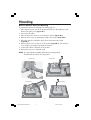
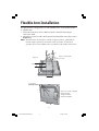
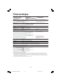
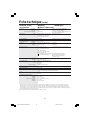
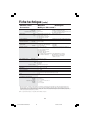
User's Manual
MultiSync LCD1770V
MultiSync LCD1770NX
MultiSync LCD1770NXM
Index
Warning .................................................................................................................... 1
Contents ................................................................................................................. 2
Sound bar Setup ................................................................................................... 3
Display Setup ......................................................................................................... 4
Mounting ................................................................................................................ 8
Flexible Arm Installation .................................................................................... 9
Controls ................................................................................................................ 10
Recommended Use ............................................................................................... 12
Specifications ...................................................................................................... 14
Features ................................................................................................................. 17
Troubleshooting ................................................................................................... 18
References ............................................................................................................. 19
Limited Warranty ................................................................................................ 20
TCO’99 ..................................................................................................................... 21
TCO’03 .................................................................................................................... 23
Manufacturer’s Recycling and Energy Information ................................... 24
Avertissement ..................................................................................................... 26
Contenu ................................................................................................................. 27
Sound bar Setup ................................................................................................. 28
Display Setup ....................................................................................................... 29
Mounting .............................................................................................................. 33
Commandes .......................................................................................................... 35
Usage recommandé ............................................................................................ 37
Fiche technique ................................................................................................... 40
Fonctions .............................................................................................................. 43
Dépannage ............................................................................................................ 44
Références ........................................................................................................... 45
Garantie limitée .................................................................................................. 46
TCO’99 .................................................................................................................... 47
TCO’03 .................................................................................................................... 49
Informations du fabricant relatives au recylage et aux économies d’énergie ...... 50
WARNING
TO PREVENT FIRE OR SHOCK HAZARDS, DO NOT EXPOSE THIS UNIT TO RAIN OR MOISTURE. ALSO, DO NOT USE
THIS UNIT'S POLARIZED PLUG WITH AN EXTENSION CORD RECEPTACLE OR OTHER OUTLETS UNLESS THE PRONGS
CAN BE FULLY INSERTED.
REFRAIN FROM OPENING THE CABINET AS THERE ARE HIGH VOLTAGE COMPONENTS INSIDE. REFER SERVICING
TO QUALIFIED SERVICE PERSONNEL.
CAUTION
CAUTION: TO REDUCE THE RISK OF ELECTRIC SHOCK, MAKE SURE POWER CORD IS UNPLUGGED FROM
WALL SOCKET. TO FULLY DISENGAGE THE POWER TO THE UNIT, PLEASE DISCONNECT THE POWER
CORD FROM THE AC OUTLET.DO NOT REMOVE COVER (OR BACK). NO USER SERVICEABLE PARTS
INSIDE. REFER SERVICING TO QUALIFIED SERVICE PERSONNEL.
This symbol warns user that uninsulated voltage within the unit may have sufficient magnitude to cause
electric shock. Therefore, it is dangerous to make any kind of contact with any part inside this unit.
This symbol alerts the user that important literature concerning the operation and maintenance of this
unit has been included. Therefore, it should be read carefully in order to avoid any problems.
Canadian Department of Communications Compliance Statement
DOC: This Class B digital apparatus meets all requirements of the Canadian
Interference-Causing Equipment Regulations.
C-UL: Bears the C-UL Mark and is in compliance with Canadian Safety Regulations
according to CAN/CSA C22.2 No. 60950-1.
FCC Information
1. Use the attached specified cables with the MultiSync® LCD1770V™, LCD1770NX™,
and LCD1770NXM™ (L174F) color monitor so as not to interfere with radio and
television reception.
(1) Please use the supplied power cord or equivalent to ensure FCC compliance.
(2) Please use the supplied shielded video signal cable.
Use of other cables and adapters may cause interference with radio and
television reception.
2. This equipment has been tested and found to comply with the limits for a Class B digital
device, pursuant to part 15 of the FCC Rules. These limits are designed to provide
reasonable protection against harmful interference in a residential installation. This
equipment generates, uses, and can radiate radio frequency energy, and, if not installed
and used in accordance with the instructions, may cause harmful interference to radio
communications. However, there is no guarantee that interference will not occur in a
particular installation. If this equipment does cause harmful interference to radio or
television reception, which can be determined by turning the equipment off and on, the user
is encouraged to try to correct the interference by one or more of the following measures:
• Reorient or relocate the receiving antenna.
• Increase the separation between the equipment and receiver.
• Connect the equipment into an outlet on a circuit different from that to which the receiver
is connected.
• Consult your dealer or an experienced radio/TV technician for help.
If necessary, the user should contact the dealer or an experienced radio/television technician
for additional suggestions. The user may find the following booklet, prepared by the Federal
Communications Commission, helpful: ”How to Identify and Resolve Radio-TV Interference
Problems.“ This booklet is available from the U.S. Government Printing Office, Washington,
D.C., 20402, Stock No. 004-000-00345-4.
1
LCD17PISAManual080604.p65
1
8/6/04, 5:14 PM
Contents
Your new NEC MultiSync® LCD monitor box* should contain the
following:
• MultiSync LCD1770V, LCD1770NX, or LCD1770NXM monitor with height adjustable stand
• Power Cord
• User’s Manual
• Video Signal Cable
• Cable Management Cover
• USB Cable (NX/NXM only)
• Audio Cable (NXM only)
• Sound bar (NXM only)
• Thumbscrews x 2 (NXM only)
Power Cord
Video Signal Cable
Cable
Management
Cover
Sound bar (NXM only)
Thumbscrews
(NXM only)
User's Manual
MultiSync LCD1770V
MultiSync LCD1770NX
MultiSync LCD1770NXM
User’s Manual
USB Cable
(NX/NXM
only)
Audio Cable
(NXM only)
* Remember to save your original box and packing material to transport or ship the monitor.
2
LCD17PISAManual080604.p65
2
8/6/04, 5:14 PM
Sound bar Setup
To attach the Sound bar to your LCD1770NXM, follow these instructions. Note:
this setup is only for the LCD1770NXM. If you have purchase an LCD1770V or
LCD1770NX, please move to the next page.
1. Turn off the computer.
2. Place hands on each side of the display to tilt up the panel and then lift up to the
highest position.
3. Use the two thumb screws included to attach the Sound bar to the display (Figure SB.1).
4. Turn the volume control down on the Soundbar (Figure SB.2).
5. Connect the light blue color audio cable plug to the light blue jack of Sound bar (Figure
SB.1). Connect the other end of the audio cable into the back of your computer.
NOTE: Headphones may be connected to the headphones jack on the right side of the
Sound bar (Figure SB.2). Headphones can be purchased from your local electronics
store.
6. Connect the DC power cable of Sound bar to DC-OUT terminal of display (Figure SB.1).
7. You are now ready to move to the next step in setting up your MultiSync LCD.
Figure SB.1
DC-OUT Terminal
of Display
Thumb
Screw
Thumb
Screw
Audio DC Power
Cable
Cable
Figure SB.2
Headphone Jack
VOL.
VOL.
Volume Control
3
LCD17PISAManual080604.p65
3
8/6/04, 5:14 PM
Display Setup
To attach the MultiSync® LCD monitor to your system, follow these instructions:
1. Turn off the power to your computer.
2. For the PC or MAC with DVI digital output (NX and NXM only): Connect the DVI
signal cable (not included) to the connector of the display card in your system (Figure
1). Tighten all screws.
For the PC with Analog output: Connect the 15-pin mini D-SUB signal cable to the
connector of the display card in your system (Figure 2). Tighten all screws.
For MAC setup: Connect the Macintosh cable adapter to the computer, then attach the
15-pin mini D-SUB signal cable to the Macintosh cable adapter (Figure 3). Tighten all
screws.
NOTE: To obtain the MultiSync Macintosh cable adapter, call NEC-Mitsubishi
Electronics Display of America, Inc. at (800) 632-4662.
3. Place hands on each side of the monitor to tilt the LCD panel 30-degree angle and lift
up to the highest position (Figure 4).
4. Connect all cables to the appropriate connectors (Figure 4). NOTE: If connecting both
DVI and D-sub cable, the DVI cable must be connected along side the rib on the
power cord side (Figure 4).
5. For successful cable management, place the cables in this order into the cable
management: audio cable (NXM only), power cable, and DVI cable (Figure 5).
6. Place DVI cable, audio cable (NXM only), and power cable into the specific hooks
indicated in Figure 6.
7. Place the D-Sub and the USB cable (NX and NXM only) into the specific hooks
indicated in Figure 7.
8. Make sure all cables are resting flat against the stand (Figure 7).
9. Hold the all cables firmly and place the cable cover onto the stand (Figure 8). To
remove the cable cover, lift the cover off as shown in Figure 9.
10. Connect the power cord to the power outlet (Figure 10).
NOTE: If you use this monitor at AC125-240V, please refer to Recommended Use
section of this manual for proper selection of power cord.
11. The vacation switch on the back side of the monitor must be turned on (Figure 10).
Turn on the monitor with the front power button and the computer.
NOTE: The vacation switch is a true on/off switch. If this switch is on the OFF
position, the monitor cannot be turned on using the front button. DO NOT switch
on/off repeatedly.
12. Analog input only: No-Touch Auto Adjust automatically adjusts the monitor to optimal
settings upon initial setup for most timings. For further adjustments, use the following
OSM® controls:
• Auto Adjust Contrast
• Auto Adjust
Refer to the Controls section of this User ’s Manual for a full description of these
OSM controls.
NOTE: For download information on the Windows® 95/98/Me/2000/XP INF file for
your monitor, refer to the References section of this User’s Manual.
NOTE: If you have any problems, please refer to the Troubleshooting section of this
User’s Manual.
4
LCD17PISAManual080604.p65
4
8/6/04, 5:14 PM
Display Setup –continued
Figure 1
Figure 2
DVI Signal Cable
(not included)
(NX and NXM only)
Figure 3
Macintosh Cable Adapter (not included)
Note: Some Macintosh systems do not require a
Macintosh Cable Adapter
30˚ Tilt
Figure 4
Figure 5
DVI Cable
(Top)
Highest
Stand
Position
Power Cable
(Middle)
Audio Cable
(Bottom)
(NMX only)
DVI Cable
Figure 6
DVI Cable
Audio Cable
Ridge
Power Cable
(NMX only)
5
LCD17PISAManual080604.p65
5
8/6/04, 5:14 PM
Display Setup –continued
Figure 7
D-Sub Cable
USB Cable
(NX and NMX only)
Flat
Figure 8
Figure 9
Insert
Top First
Then
Bottom
Figure 10
Vacation
Switch
ON Position
Power Button
6
LCD17PISAManual080604.p65
6
OFF Position
8/6/04, 5:14 PM
Display Setup –continued
Raise and Lower Monitor Screen
The monitor may be raised or lowered. To raise or lower screen, place hands on
each side of the monitor and lift or lower to the desired height (Figure RL.1).
NOTE: Handle with care when raising or lowering the monitor screen.
Figure RL.1
Tilt and Swivel
Grasp both sides of the monitor screen with your hands and adjust the tilt and
swivel as desired (Figure TS.1).
NOTE: Handle with care when tilting and swiveling the monitor screen.
Figure TS.1
7
LCD17PISAManual080604.p65
7
8/6/04, 5:14 PM
Mounting
Remove Monitor Stand for Mounting
To prepare the monitor for alternate mounting purposes:
1. Place hands on each side of the monitor and lift up to the highest position.
Remove the cable cover (Figure M.1).
2. Disconnect all cables.
3. Place monitor face down on a non-abrasive surface (Figure M.2).
4. Remove the 2 screws connecting the stand to the monitor (FigureM.2).
5. Lift up the stand to unlatch the upper hooks and remove the stand
(FigureM.3).
6. Remove the 2 screws on the top of the monitor (FigureM.4). The monitor is
now ready for mounting in an alternate manner.
7. Connect the cables to the back of the monitor.
8. Reverse this process to reattach stand.
NOTE: Use only VESA-compatible alternative mounting method.
Handle with care when removing stand.
Figure M.2
Figure M.1
Figure M.3
Figure M.4
8
LCD17PISAManual080604.p65
8
8/6/04, 5:15 PM
Flexible Arm Installation
This LCD monitor is designed for use with a flexible arm. To mount the monitor
to a flexible arm:
1. Follow the instructions on how Remove Monitor Stand for Mounting to
remove the stand.
2. Using the 4 screws from the stand removal and attach the arm to the monitor
(Figure F.1).
NOTE: The LCD monitor should only be used with an approved arm (e.g. GS mark). To
meet the safety requirements, the monitor must be mounted to an arm which
guaranties the necessary stability under consideration of the weight of the monitor.
Thickness of Bracket (Arm)
Figure F.1
2.0~3.2mm
100mm
100mm
4 Screws (4M)
(Max Depth: 8.5mm)
Weight of LCD assembly: 4.7kg (MAX)
4.2kg (LCD1770V)
4.3kg (LCD1770NX)
4.7kg (LCD1770NXM)
9
LCD17PISAManual080604.p65
9
8/6/04, 5:15 PM
Controls
OSM® (On-Screen Manager) control buttons on the front of the monitor function
as follows:
To access OSM menu, press any of the control buttons (MENU/EXIT, Left, Right, Down, Up).
To change signal input, press the SELECT button (NX and NXM only).
NOTE: OSM must be closed in order to change signal input.
Button
Menu
MENU/EXIT
Exits the OSM controls.
Exits to the OSM main menu.
Left/Right
Moves the highlighted area left/right to select control menus.
Moves the bar left/right to increase or decrease the adjustment.
Down/Up
Moves the highlighted area down/up to select one of the controls.
SELECT
Active Auto Adjust function. Enter the OSM sub menu.
RESET
Resets the highlighted control menu to the factory setting.
NOTE: When RESET is pressed in the main and sub-menu, a warning window will appear
allowing you to cancel the RESET function by pressing the MENU/EXIT button.
Brightness/Contrast Controls
BRIGHTNESS
Adjusts the overall image and background screen brightness.
CONTRAST
Adjusts the image brightness in relation to the background.
AUTO Contrast (Analog input only)
Adjusts the image displayed to optimal settings.
Auto Adjust (Analog input only)
Automatically adjusts the Image Position, H. Size and Fine settings.
Image Controls (Analog input only)
LEFT / RIGHT
Controls Horizontal Image Position within the display area of the LCD.
DOWN / UP
Controls Vertical Image Position within the display area of the LCD.
H.SIZE
Adjusts the horizontal size by increasing or decreasing this setting.
FINE
Improves focus, clarity and image stability by increasing or decreasing this setting.
AccuColor® Control Systems
AccuColor® Control Systems: Six color presets select the desired color setting (sRGB
and NATIVE color presets are standard and cannot be changed).
R,G,B: Increases or decreases Red, Green or Blue color depending upon which is
selected. The change in color will appear on screen and the direction (increase or
decrease) will be shown by the bars.
10
LCD17PISAManual080604.p65
10
8/6/04, 5:15 PM
Controls –continued
NATIVE: Original color presented by the LCD panel that is unadjustable.
sRGB: sRGB mode dramatically improves the color fidelity in the desktop
environment by a single standard RGB color space. With this color supported
environment, the operator could easily and confidently communicate color
without further color management overhead in the most common situations.
Tools
OFF TIMER: Monitor will automatically power-down when the end user has selected
a predetermined amount of time.
HOT KEY: You can adjust the brightness and contrast directly. When this function is
set to ON, you can adjust the brightness with left or right control and contrast with
up or down control while the OSM menu is off.
FACTORY PRESET: Selecting Factory Preset allows you to reset all OSM control
settings back to the factory settings. The RESET button will need to be held down
for several seconds to take effect. Individual settings can be reset by highlighting
the control to be reset and pressing the RESET button.
Menu Tools
LANGUAGE: OSM® control menus are available in eight languages.
OSM LEFT/RIGHT: You can choose where you would like the OSM control
image to appear horizontally on your screen.
OSM DOWN/UP: You can choose where you would like the OSM control image to
appear vertically on your screen.
OSM TURN OFF: The OSM control menu will stay on as long as it is in use. In the
OSM Turn Off submenu, you can select how long the monitor waits after the last
touch of a button to shut off the OSM control menu.
OSM LOCK OUT: This control completely locks out access to all OSM control
functions without Brightness and Contrast. When attempting to activate OSM
controls while in the Lock Out mode, a screen will appear indicating the OSM
controls are locked out. To activate the OSM Lock Out function, press SELECT,
then right control button and hold down simultaneously. To deactivate the OSM
Lock Out, press SELECT, then left control button and hold down simultaneously
while in the OSM menu.
RESOLUTION NOTIFIER: This optimal resolution is 1280 x 1024. If ON is selected,
a message will appear on the screen after 30 seconds, notifying you that the
resolution is not at 1280 x 1024.
Information
The Information menu indicates the current input, display resolution, horizontal and
vertical frequency, and polarity settings of the monitor. The model and serial
numbers of your monitor are also indicated.
11
LCD17PISAManual080604.p65
11
8/6/04, 5:15 PM
Recommended Use
Safety Precautions and Maintenance
FOR OPTIMUM PERFORMANCE, PLEASE NOTE
THE FOLLOWING WHEN SETTING UP AND USING
THE MULTISYNC® LCD COLOR MONITOR:
• DO NOT OPEN THE MONITOR. There are no user serviceable parts inside and opening or
removing covers may expose you to dangerous shock hazards or other risks. Refer all servicing to
qualified service personnel.
• Do not spill any liquids into the cabinet or use your monitor near water.
• Do not insert objects of any kind into the cabinet slots, as they may touch dangerous voltage
points, which can be harmful or fatal or may cause electric shock, fire or equipment failure.
• Do not place any heavy objects on the power cord. Damage to the cord may cause shock or fire.
• Do not place this product on a sloping or unstable cart, stand or table, as the monitor may fall,
causing serious damage to the monitor.
• When operating the MultiSync LCD monitor with its AC 125-240V power supply, use a power
supply cord that matches the power supply voltage of the AC power outlet being used. The power
supply cord you use must have been approved by and comply with the safety standards of your
country. (Type H05VV-F should be used in Europe)
• In UK, use a BS-approved power cord with molded plug having a black (5A) fuse installed for use
with this monitor. If a power cord is not supplied with this monitor, please contact your supplier.
• Do not place any objects onto the monitor and do not use the monitor outdoors.
• The inside of the flourescent tube located within the LCD monitor contains mercury.
Please follow the bylaws or rules of your municipality to dispose of the tube properly.
• Do not bend power cord.
• Do not use monitor in high temperatured, humid, dusty, or oily areas.
• Do not cover vent on monitor.
Immediately unplug your monitor from the wall outlet and refer servicing to qualified service
personnel under the following conditions:
• When the power supply cord or plug is damaged.
• If liquid has been spilled, or objects have fallen into the monitor.
• If the monitor has been exposed to rain or water.
• If the monitor has been dropped or the cabinet damaged.
• If the monitor does not operate normally by following operating instructions.
• If glass is broken, handle with care.
• If monitor or glass is broken, do not come in contact with the liquid crystal and handle with care.
• Allow adequate ventilation around the monitor so that heat can properly dissipate. Do
not block ventilated openings or place the monitor near a radiator or other heat
sources. Do not put anything on top of monitor.
• The power cable connector is the primary means of detaching the system from the
power supply. The monitor should be installed close to a power outlet which is easily accessible.
• Handle with care when transporting. Save packaging for transporting.
CAUTION
Image Persistence
Please be aware that LCD Technology may experience a phenomena known as Image Persistence.
Image Persistence occurs when a residual or “ghost” image of a previous image remains visible on
the screen. Unlike CRT monitors, LCD monitors’ image persistence is not permanent, but constant
images being displayed for a long period of time should be avoided.
To alleviate image persistence, turn off the monitor for as long as the previous image was
displayed. For example, if an image was on the monitor for one hour and a residual image
remains, the monitor should be turned off for one hour to erase the image.
As with all personal display devices, NEC-Mitsubishi Electronics Display recommends displaying
moving images and using a moving screen saver at regular intervals whenever the screen is idle or
turning off the monitor when not in use.
12
LCD17PISAManual080604.p65
12
8/6/04, 5:15 PM
Recommended Use –continued
CORRECT PLACEMENT AND ADJUSTMENT OF THE MONITOR
CAN REDUCE EYE, SHOULDER AND NECK FATIGUE. CHECK THE
FOLLOWING WHEN YOU POSITION THE MONITOR:
• For optimum performance, allow 20 minutes for
warm-up.
• Adjust the monitor height so that the top of the screen is at or
slightly below eye level. Your eyes should look slightly downward
when viewing the middle of the screen.
• Position your monitor no closer than 16 inches and no further
away than 28 inches from your eyes. The optimal distance is
20 inches.
• Rest your eyes periodically by focusing on an object at least
20 feet away. Blink often.
• Position the monitor at a 90° angle to windows and other light
sources to minimize glare and reflections. Adjust the monitor
tilt so that ceiling lights do not reflect on your screen.
• If reflected light makes it hard for you to see your screen, use an anti-glare filter.
• Adjust the monitor’s brightness and contrast controls to enhance readability.
• Use a document holder placed close to the screen.
• Position whatever you are looking at most of the time (the screen or
reference material) directly in front of you to minimize turning your head
while you are typing.
• Get regular eye checkups.
Ergonomics
To realize the maximum ergonomics benefits, we recommend the following:
• Use the preset Size and Position controls with standard signals
• Use the preset Color Setting
• Use non-interlaced signals with a vertical refresh rate between 60-75Hz
• Do not use primary color blue on a dark background, as it is difficult to see and
may produce eye fatigue to insufficient contrast.
For more detailed information on setting up a healthy work environment, write the American National
Standard for Human Factors Engineering of Visual Display Terminal Workstations – ANSI-HFS
Standard No. 100-1988 – The Human Factors Society, Inc. P.O. Box 1369, Santa Monica,
California 90406.
Cleaning the LCD Panel
• When the liquid crystal panel is stained with dust or dirt, please wipe with soft cloth gently.
• Please do not rub the LCD panel with hard material.
• Please do not apply pressure to the LCD surface.
• Please do not use OA cleaner it will cause deterioration or discolor on the LCD surface.
Cleaning the Cabinet
• Unplug the power supply
• Gently wipe the cabinet with a soft cloth
• To clean the cabinet, dampen the cloth with a neutral detergent and water, wipe the cabinet
and follow with a dry cloth.
NOTE: Many plastics are used on the surface of the cabinet. DO NOT clean with benzene,
thinner, alkaline detergent, alcoholic system detergent, glass cleaner, wax, polish cleaner, soap
powder, or insecticide. Do not touch rubber or vinyl to the cabinet for a long time. These types
of fluids and fabrics can cause the paint to deteriorate, crack or peel.
13
LCD17PISAManual080604.p65
13
8/6/04, 5:15 PM
Specifications
Monitor
Specifications
MultiSync® LCD1770V™
Monitor
LCD Module
Diagonal :
Viewable Image Size :
Native Resolution (Pixel Count) :
17.0 inch
17.0 inch
1280 x 1024
Input Signal
Video :
Sync :
Active matrix; thin film transistor (TFT)
liquid crystal display (LCD); 0.264 mm dot
pitch; 250cd/m2 white luminence;
450:1 contrast ratio, typical
ANALOG 0.7 Vp-p/75 Ohms
Separate sync. TTL Level
Horizontal sync. Positive/Negative
Vertical sync. Positive/Negative
Display Colors
Maximum
16,194,277
Left/Right :
Dependent on display card used.
80°/80° (CR>5)
Viewing Angles
Up/Down :
75°/70° (CR>5)
Synchronization
Range
Horizontal :
Vertical :
31.5 kHz to 81.0 kHz
56.0 Hz to 75.0 Hz
Resolutions Supported
Active Display Area
Notes
Automatically
Automatically
720 x 400*1 :VGA text
Some systems may not support all modes listed.
640 x 480*1 @ 60 Hz to 75 Hz
800 x 600*1 @ 56 Hz to 75 Hz
832 x 624*1 @ 75 Hz
1024 x 768*1 @ 60 Hz to 75 Hz
1152 x 870*1 @ 75 Hz
1280 x 1024 @ 60 Hz to 75 Hz .......................... NEC-Mitsubishi Electronics Display cites
recommended resolution at 60 Hz for
optimal display performance.
Horizontal :
Vertical :
337.9 mm/13.3 inches
270.3 mm/10.6 inches
Power Supply
100 – 240 V ~ 50/60 Hz
Current Rating
0.7 – 0.36A
Dimensions
367.0 mm (W) x 362.5-472.5 mm (H) x 198.0 mm (D)
14.4 inches (W) x 14.3-18.6 inches (H) x 7.8 inches (D)
Weight
6.0 kg
13.2 lbs
Environmental Considerations
Operating Temperature :
Humidity :
Feet :
Storage Temperature :
Humidity :
Feet :
5°C to 35°C/41°F to 95°F
30% to 80%
0 to 10,000 Feet
-10°C to 60°C/14°F to 140°F
10% to 85%
0 to 30,000 Feet
*1 Interpolated Resolutions: When resolutions are shown that are lower than the pixel count of the LCD module, text may appear different. This is
normal and necessary for all current flat panel technologies when displaying non-native resolutions full screen. In flat panel technologies, each
dot on the screen is actually one pixel, so to expand resolutions to full screen, an interpolation of the resolution must be done.
NOTE: Technical specifications are subject to change without notice.
14
LCD17PISAManual080604.p65
14
8/6/04, 5:15 PM
Specifications –continued
Monitor
Specifications
MultiSync® LCD1770NX
Monitor
LCD Module
Diagonal :
Viewable Image Size :
Native Resolution (Pixel Count) :
17.0 inch
17.0 inch
1280 x 1024
Active matrix; thin film transistor (TFT)
liquid crystal display (LCD); 0.264 mm dot
pitch; 250cd/m2 white luminence;
500:1 contrast ratio, typical
Input Signal
Video :
Sync :
ANALOG 0.7 Vp-p/75 Ohms
Separate sync. TTL Level
Horizontal sync. Positive/Negative
Vertical sync. Positive/Negative
Digital Input: DVI
16,194,277
Dependent on display card used.
Display Colors
Maximum
Left/Right :
80°/80° (CR>5)
Viewing Angles
Up/Down :
85°/75° (CR>5)
Synchronization
Range
Horizontal :
31.5 kHz to 81.0 kHz (Analog)
31.5 kHz to 69.0 kHz (Digital)
56.0 Hz to 75.0 Hz
Vertical :
Resolutions Supported
Active Display Area
USB Hub
Notes
Automatically
Automatically
Automatically
720 x 400*1 :VGA text
Some systems may not support all modes listed.
640 x 480*1 @ 60 Hz to 75 Hz
800 x 600*1 @ 56 Hz to 75 Hz
832 x 624*1 @ 75 Hz
1024 x 768*1 @ 60 Hz to 75 Hz
1152 x 870*1 @ 75 Hz
1280 x 1024 @ 60 Hz to 75 Hz (Analog) ......... NEC-Mitsubishi Electronics Display cites
1280 x 1024 @ 60 Hz (Digital)
recommended resolution at 60 Hz for
optimal display performance.
Horizontal :
Vertical :
337.9 mm/13.3 inches
270.3 mm/10.6 inches
I/P:
Port:
USB Specification Revision 2.0
Upstream 1
Downstream 4
Maximum 0.5A per port
Load Current:
Power Supply
100 – 240 V ~ 50/60 Hz
Current Rating
0.7 – 0.36A
Dimensions
367.0 mm (W) x 362.5-472.5 mm (H) x 198.0 mm (D)
14.4 inches (W) x 14.3-18.6 inches (H) x 7.8 inches (D)
Weight
6.1 kg
13.4 lbs
Environmental Considerations
Operating Temperature :
Humidity :
Feet :
Storage Temperature :
Humidity :
Feet :
5°C to 35°C/41°F to 95°F
30% to 80%
0 to 10,000 Feet
-10°C to 60°C/14°F to 140°F
10% to 85%
0 to 30,000 Feet
*1 Interpolated Resolutions: When resolutions are shown that are lower than the pixel count of the LCD module, text may appear different. This is
normal and necessary for all current flat panel technologies when displaying non-native resolutions full screen. In flat panel technologies, each
dot on the screen is actually one pixel, so to expand resolutions to full screen, an interpolation of the resolution must be done.
NOTE: Technical specifications are subject to change without notice.
15
LCD17PISAManual080604.p65
15
8/6/04, 5:15 PM
Specifications –continued
Monitor
Specifications
MultiSync® LCD1770NXM
Monitor
LCD Module
Diagonal :
Viewable Image Size :
Native Resolution (Pixel Count) :
17.0 inch
17.0 inch
1280 x 1024
Active matrix; thin film transistor (TFT)
liquid crystal display (LCD); 0.264 mm dot
pitch; 250cd/m2 white luminence;
500:1 contrast ratio, typical
Input Signal
Video :
Sync :
ANALOG 0.7 Vp-p/75 Ohms
Separate sync. TTL Level
Horizontal sync. Positive/Negative
Vertical sync. Positive/Negative
Digital Input: DVI
16,194,277
Dependent on display card used.
Display Colors
Maximum
Left/Right :
80°/80° (CR>5)
Viewing Angles
Up/Down :
85°/75° (CR>5)
Synchronization
Range
Horizontal :
31.5 kHz to 81.0 kHz (Analog)
31.5 kHz to 69.0 kHz (Digital)
56.0 Hz to 75.0 Hz
Vertical :
Resolutions Supported
Active Display Area
Notes
Automatically
Automatically
Automatically
720 x 400*1 :VGA text
Some systems may not support all modes listed.
640 x 480*1 @ 60 Hz to 75 Hz
800 x 600*1 @ 56 Hz to 75 Hz
832 x 624*1 @ 75 Hz
1024 x 768*1 @ 60 Hz to 75 Hz
1152 x 870*1 @ 75 Hz
1280 x 1024 @ 60 Hz to 75 Hz (Analog) ......... NEC-Mitsubishi Electronics Display cites
1280 x 1024 @ 60 Hz (Digital)
recommended resolution at 60 Hz for
optimal display performance.
Horizontal :
Vertical :
USB Hub
I/P:
Port:
Speakers
Practical Audio Output:
337.9 mm/13.3 inches
270.3 mm/10.6 inches
USB Specification Revision 2.0
Upstream 1
Downstream 4
Maximum 0.5A per port
Load Current:
2.0 W + 2.0 W
Power Supply
100 – 240 V ~ 50/60 Hz
Current Rating
0.7 – 0.36A
Dimensions
367.0 mm (W) x 368.6-472.5 mm (H) x 198.0 mm (D)
14.4 inches (W) x 14.5-18.6 inches (H) x 7.8 inches (D)
Weight
6.5 kg
14.3 lbs
Environmental Considerations
Operating Temperature :
Humidity :
Feet :
Storage Temperature :
Humidity :
Feet :
5°C to 35°C/41°F to 95°F
30% to 80%
0 to 10,000 Feet
-10°C to 60°C/14°F to 140°F
10% to 85%
0 to 30,000 Fee