1
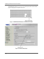
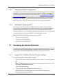
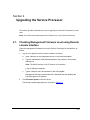
EXPRESS5800/A1160 Service Processor Troubleshooting Guide Proprietary Notice and Liability Disclaimer The information disclosed in this document, including all designs and related materials, is the valuable property of NEC Corporation of America, Inc. and/or its licensors. NEC Corporation of America and/or its licensors, as appropriate, reserve all patent, copyright and other proprietary rights to this document, including all design, manufacturing, reproduction, use, and sales rights thereto, except to the extent said rights are expressly granted to others. The NEC Corporation of America product(s) discussed in this document are warranted in accordance with the terms of the Warranty Statement accompanying each product. However, actual performance of each product is dependent upon factors such as system configuration, customer data, and operator control. Since implementation by customers of each product may vary, the suitability of specific product configurations and applications must be determined by the customer and is not warranted by NEC Corporation of America. To allow for design and specification improvements, the information in this document is subject to change at any time, without notice. Reproduction of this document or portions thereof without prior written approval of NEC Corporation of America is prohibited. Trademarks Windows is a registered trademark of Microsoft Corporation. Intel and Itanium are registered trademarks of Intel Corporation. All other product, brand, or trade names used in this publication are the trademarks or registered trademarks of their respective trademark owners. PN: 456-01807-000 December, 2008 Copyright 2008 NEC Corporation of America 10850 Gold Center Drive, Suite 200, Rancho Cordova, CA 95670 All Rights Reserved Contents Section 1 Introduction ....................................................................1-1 1.1. Documentation Updates..................................................................... 1-1 1.2. Preparing to Restore the Service Processor ...................................... 1-1 1.2.1. Identifying the Boot Cell ..................................................................... 1-1 1.2.2. Recording Partition Configuration ...................................................... 1-3 1.2.3. Workstation Requirements ................................................................. 1-3 1.3. Accessing the Service Processor....................................................... 1-3 1.3.1. Logging On to Partition Remote Console Interface............................ 1-3 1.3.2. Accessing EXPRESSSCOPE® Monitor Interface.............................. 1-4 Section 2 Upgrading the Service Processor.................................2-1 2.1. Checking Management Firmware Level using Remote console interface ............................................................................................. 2-1 2.2. Obtaining Releases from the Support Site ......................................... 2-3 2.3. Updating Management Firmware using Remote console interface ... 2-3 Section 3 Troubleshooting the Service Processor ......................3-1 3.1. Possible Problem Symptoms for the Service Processor .................... 3-1 3.2. Loss of Communication With Partition Remote console interface ..... 3-1 3.2.1. Pinging the Service Processor ........................................................... 3-1 3.2.2. Verifying Network Access to Your System.......................................... 3-2 3.2.3. Verifying Partition Network Settings ................................................... 3-3 3.2.4. Rebooting the Service Processor....................................................... 3-4 3.2.5. Restoring the Service Processor to Default Settings ......................... 3-4 3.3. Cell Is Not Responding ...................................................................... 3-5 3.3.1. Rebooting the Service Processor....................................................... 3-5 3.3.2. Checking Cell Interconnect Cable Connections ................................. 3-6 3.3.3. Restoring the Service Processor to Default Settings ......................... 3-6 3.4. Error Messages Displayed on EXPRESSSCOPE® Monitor LCD...... 3-6 3.4.1. Message: “ID Indeterminate”.............................................................. 3-7 3.4.2. Message: “ID Conflict”........................................................................ 3-7 iii Contents 3.4.3. Message: “Segment Conflict”............................................................. 3-8 3.4.4. Message: “Segment Down” ............................................................... 3-9 3.4.5. Message: “Switch Error” .................................................................. 3-10 Section 4 Restoring the Service Processor ................................. 4-1 4.1. Before Restoring to Default Settings.................................................. 4-1 4.2. Restoring Service Processor to Default Settings ............................... 4-1 4.2.1. Default Settings.................................................................................. 4-1 4.2.2. Restoring the Default Settings ........................................................... 4-3 4.2.3. Configuring After Restoring ................................................................ 4-3 Section 5 Configuring the Service Processor After Restoring ... 5-4 5.1. Configuring After Updating Management Firmware ........................... 5-4 5.2. Configuring After Restoring Default Settings ..................................... 5-4 5.2.1. Reconfiguring Service Processor on a Non-boot Cell ........................ 5-4 5.2.2. Reconfiguring Service Processor on a Boot Cell ............................... 5-5 5.2.3. Reconfiguring Service Processor on a Boot Cell in a Multiple Cell Partition .............................................................................................. 5-5 5.3. Configuration Procedures .................................................................. 5-6 5.3.1. Configuring Network Settings ............................................................ 5-6 5.3.2. Resolving Partitioning Inconsistencies............................................. 5-10 5.3.3. Creating Partitions ........................................................................... 5-10 5.3.4. Moving Cells to Other Partitions ....................................................... 5-11 5.3.5. Specifying Partition Settings ............................................................ 5-12 5.3.6. Adding User Credentials using Remote console interface ............... 5-13 5.3.7. Eliminating Browser Startup Warnings using Remote console interface ........................................................................................... 5-14 5.3.8. Configuring Alerts and the SMTP Server using Remote console interface ........................................................................................... 5-15 Appendix A iv Related Documents and Web Resources ........ A-1 A.1 Express5800/A1160 Documentation Library ...................................... A-1 A.2 Web Resources ................................................................................. A-2 Figures Figures Figure 1-1 EXPRESSSCOPE® Monitor LCD Main Screen Layout .............................. 1-2 Figure 1-2 Partition Setting Page .................................................................................. 1-2 Figure 2-1 Management Firmware Update Page.......................................................... 2-2 Figure 2-2 Management Firmware Revision Status ...................................................... 2-2 Figure 2-3 Management Firmware Updates Page ........................................................ 2-3 Figure 2-4 Management Firmware Revision Status ...................................................... 2-4 Figure 3-1 Location of Maintenance LAN Port .............................................................. 3-2 Figure 3-2 Location of Boot Cell Indicator on Main Screen of EXPRESSSCOPE® Monitor Interface .................................................................................................... 3-3 Figure 3-3 Location of Management Board Reset Button............................................. 3-4 Figure 3-4 Location of Management Board Reset Button............................................. 3-5 Figure 3-5 Location of Management Board Reset Button........................................... 3-10 Figure 5-1 Settings Reserved ....................................................................................... 5-7 Figure 5-2 Expanded Network Menu ............................................................................ 5-8 Figure 5-3 Setting IP Address Value ............................................................................. 5-9 Figure 5-4 Applying IP Address Changes ..................................................................... 5-9 Figure 5-5 Partitioning Page ....................................................................................... 5-10 Figure 5-6 User Management Page............................................................................ 5-13 Figure 5-7 User Management Add New User Page.................................................... 5-14 Figure 5-8 SMTP Page ............................................................................................... 5-16 Figure 5-9 Alert Management Page ............................................................................ 5-17 Figure 5-10 Alert Management - Modify Email ............................................................ 5-18 Figure 5-11 Alert Management - Modify SNMP Trap .................................................. 5-19 v Using This Guide Using This Guide This guide provides the information necessary for upgrading firmware on your Service Processor or troubleshooting software problems with your Service Processor. Who Should Use This Guide This guide is intended for system administrators and facilities personnel who are responsible for installing and administering Express5800/A1160 server. Symbols and Conventions This guide uses the following text conventions and graphic symbols. Warnings, cautions, and notes have the following meanings: WARNING Warnings alert you to situations that could result in serious personal injury or loss of life. CAUTION Cautions indicate situations that can damage the system hardware or software. Note: Notes give important information about the material being described. Names of keyboard keys are printed as they appear on the keyboard. For example, Ctrl, Alt, or Enter. Text or keystrokes that you enter appear as boldface type. For example, type abc123 and press ENTER. File names are printed in uppercase letters. For example, AUTOEXEC.BAT. Related Documents In addition to this guide, the following system documentation is useful. vi NECCare™ Guide The NECCare Guide contains information about NEC’s warranty and server registration. Safety Notices Safety Notices WARNING To avoid a risk of injuries, maintenance procedures require trained technical personnel. In maintenance procedures with voltages of 42.4V peak or 60Vdc or more, take safety measures, such as wearing insulated rubber gloves. Performing work without these measures may cause electric shock. In an emergency, such as a dangerous event that requires turning off the power supply, turn off the breaker at the rear of the server. Turning off the breaker may cause data destruction. Therefore, users should determine when to turn off the breaker in accordance with specified operation criteria. The server is equipped with a front stabilizer. Engage the front stabilizer during installation. For stability and to distribute the weight, also attach side stabilizers. Otherwise, the rack may topple over and cause injuries. If you extend two or more devices from the rack at the same time, the rack may topple over on you. Extend only one device from the rack at a time. Exercise great care not to hurt your fingers on the rail when you mount/dismount the equipment into/from the rack. Lithium batteries can be dangerous. Improper handling of lithium batteries may result in an explosion. Dispose of lithium batteries as required by local ordinance. Replace only with the same or equivalent type battery. A liquid crystal display is used in this server. When handling a damaged liquid crystal display, take care to avoid exposure to the liquid inside the liquid crystal display. The liquid can cause bodily harm. In the event the liquid is ingested, gargle at once and consult a doctor immediately. If the liquid comes in contact with skin or gets into the eyes, wash the skin with cool running water, or flush the eye with cool running water for at least 15 minutes and consult a doctor. The DVD-ROM drive uses a laser beam. Do not look or insert a mirror inside while the system is on. A laser beam is invisible; if your eyes get exposed to it, there is a risk of losing your eyesight. Elevated Operating Ambient Temperature – If installed in a closed or multi-unit rack assembly, the operating ambient temperature of the rack environment may be greater than the room ambient environment. Therefore, consideration should be given to vii Safety Notices installing the equipment in an environment compatible with the maximum rated ambient temperature of 89.6°F. Reduced air Flow – Installation of the equipment in a rack should be such that the amount of air flow required for safe operation of the equipment is not compromised. To prevent fires, and damage to rack equipment and supply wiring, make sure that the rated load of the power branch circuit is not exceeded. Equipment nameplate ratings should be used when addressing this concern. For more information on installation and wiring of power-related facilities, contact your electrician or local power company. To prevent electrical shock, connect all rack and rack support equipment to the same electrical circuit of the building wiring. If you are unsure, check the building wiring to avoid remote earth conditions. For safe operation, only connect the equipment to a building supply that is in accordance with current wiring regulations in your country. In the USA those wiring standards are regulated by Underwriter Laboratories (UL); in the U.K. by the Institution of Electrical Engineers, (IEE) and in Canada by the Canadian Standards Association (CSA). WARNING Some locations within the server have high voltage and therefore are very dangerous. To avoid risk of electric shock, turn off all server power and disconnect power cables before working inside the server unit. The main power of your server is turned off by turning off the power source to the server or removing the power cable. Before touching the parts in the server, wait for at least 10 to 15 seconds until residual voltage is discharged. viii Online maintenance – During and after servicing, do not leave the server door open unless necessary to perform servicing. WARNING Take care not to short live components with conductive tools, such as an adjustable wrench. To prevent shock, take care not to drop or leave conductive parts, such as a screw, in the server when servicing the system. Be careful when accessing a fan or rotating parts to avoid cutting your hand or fingers. Safety inspections – When servicing the system, check equipment that can cause harm due to deterioration, and if necessary, replace the part. Safety Notices for Users Outside of the U.S.A. and Canada PELV (Protected Extra-Low Voltage) Integrity: To ensure the extra-low voltage integrity of the equipment, connect only equipment with mains-protected electrically-compatible circuits to the external ports. Remote Earths: To prevent electrical shock, connect all local (individual office) computers and computer support equipment to the same electrical circuit of the building wiring. If you are unsure, check the building wiring to avoid remote earth conditions. Earth Bonding: For safe operation, only connect the equipment to a building supply that is in accordance with current wiring regulations in your country. In the USA those wiring standards are regulated by Underwriter Laboratories (UL); in the U.K., by the Institution of Electrical Engineers, (IEE) and in Canada by the Canadian Standards Association (CSA). ix Section 1 Introduction This guide provides the information necessary for upgrading firmware on your Service Processor or troubleshooting software problems with your Service Processor. This guide is intended for system administrators and service representatives who are responsible for installing and administering servers. You might need to load software onto your Service Processor in one of the following situations: y A management firmware upgrade becomes available. y Troubleshooting procedures recommend restoring to default settings and then upgrading to new software. Note: You cannot load the same level of software on to your Service Processor. 1.1. Documentation Updates This document contains all the information that was available at the time of publication. The latest version of the document may be found in the Product Support Web Site: http://support.necam.com/servers/Enterprise/ 1.2. Preparing to Restore the Service Processor Before you begin any upgrading or troubleshooting procedures, be sure to check the Product Support Web Site for additional instructions or late-breaking information related as it might provide additional information that could not be included in this guide. You can also download any additional documentation or software updates you might need. 1.2.1. Identifying the Boot Cell Depending on whether you are restoring a Service Processor in the boot cell, additional reconfiguration tasks such as specifying partition settings or configuring alert notifications might be required. Preparing to Restore the Service Processor You can determine if your Service Processor is in the boot cell by checking the 1-1 Preparing to Restore the Service Processor EXPRESSSCOPE® Monitor LCD on your cell or checking the remote console interface partition settings page for the partition the cell is in. Figure 1-1 EXPRESSSCOPE® Monitor LCD Main Screen Layout Figure 1-2 Partition Setting Page 1-2 Accessing the Service Processor 1.2.2. Recording Partition Configuration You might lose your partition configuration while troubleshooting your Service Processor, especially if you restore the Service Processor in a single-cell partition. If possible, log on to the remote console interface for your partition (see 1.3.1 Logging On to Partition Remote Console Interface) and use the save or print function of your browser to archive a copy of the remote console page so that you have a record of your current partition configuration and settings, such as power restore policy and fault behavior. Use this information later to verify your partition configuration or reconfigure the partition. 1.2.3. Workstation Requirements To access your Service Processor through the partition remote console interface, ensure that your workstation is on the same LAN segment as your system or that your partition IP address is routable. If a partition or cell in your system does not use a routable IP address, it is not accessible to network entities beyond its LAN segment (that is, network routers do not forward traffic to or from the partition or cell). Note: IP addresses in the following ranges are not routable: y 10.0.0.0 to 10.255.255.255 y 172.16.0.0 to 172.31.255.255 y 192.168.0.0 to 192.168.255.255 1.3. Accessing the Service Processor Procedures in this guide might require you to access your Service Processors. You can access each Service Processor remotely through the partition remote console interface or through the EXPRESSSCOPE® Monitor interface on the front of each cell. 1.3.1. Logging On to Partition Remote Console Interface To access the partition remote console interface 1. Type the maintenance LAN (MLAN) address of the partition in the browser address box. Note: The MLAN address is the IP address on the partition and cell menus on the EXPRESSSCOPE® Monitor interface. A log-on dialog box appears. 2. Type a valid user name and password, and click Log On. Management firmware authenticates the credentials before displaying the requested remote console interface. 1-3 Accessing the Service Processor 1.3.2. Accessing EXPRESSSCOPE® Monitor Interface The EXPRESSSCOPE® Monitor interface is on the front of each cell. You must be physically present to operate the buttons and view the LCD and LEDs. 1-4 Section 2 Upgrading the Service Processor This section provides information on how to upgrade your Service Processors to a new level. Note: You cannot reload the same level of software on to your Service Processor. 2.1. Checking Management Firmware Level using Remote console interface Check the management firmware level on the Service Processors for the partition, as follows: 1. Log on to the partition remote console interface, as follows: a. Open a browser on a management server or connected workstation. b. Type the maintenance LAN (MLAN) address of the partition in the browser address box. Note: The MLAN address is the IP address of the partition. A log-on dialog box appears. c. Type a valid user name and password, and click Log On. Management firmware authenticates the credentials and then displays the summary page for the partition. 2. Click Firmware Update in the left column. The firmware update page appears, as shown in Figure 2-1. 2-1 Checking Management Firmware Level using Remote console interface Figure 2-1 Management Firmware Update Page 3. Click Display Current Firmware Status and Revision. A dialog box appears containing the current management firmware revision level for each cell in the partition, as shown in Figure 2-2. All cells in the partition should have the same firmware level. Note: If a cell is not listed in the dialog box, it is AC powered off or otherwise not communicating properly. Figure 2-2 Management Firmware Revision Status 2-2 Obtaining Releases from the Support Site 2.2. Obtaining Releases from the Support Site If you need to install later release levels, such as management firmware or BIOS, you can obtain the desired versions from the Product Support Web Site: http://support.necam.com/servers/Enterprise/ 2.3. Updating Management Firmware using Remote console interface You can determine the management firmware levels on the Service Processors and update the firmware if necessary, provided you can access the partition remote console interface, as follows: 1. Navigate to the firmware update page of the partition remote console interface, as shown in Figure 2-3. Figure 2-3 Management Firmware Updates Page 2. To update the management firmware on the partition, click Browse on the firmware update page, navigate to the location of the saved firmware update file, and click Load. The firmware revision is loaded and distributed to the Service Processor of each 2-3 Updating Management Firmware using Remote console interface member cell of the partition that is AC powered on. The update takes several minutes to complete. Initially, a dialog box is displayed saying that the update is in progress. When the update finishes, all cells should have the same firmware level. Each Service Processor performs a reset action, and the connection to the remote console interface is lost. 3. Refresh the page and log on to restore the partition remote console interface. 4. Navigate to the firmware update page and click Display Current Firmware Status and Revision to check that the current management firmware level is correct. A dialog box appears containing the current management firmware revision level for each cell in the partition, as shown in Figure 2-4. All cells in the partition should have the same firmware level. Note: If a cell is not listed in the dialog box, it is AC powered off or otherwise not communicating properly. Figure 2-4 Management Firmware Revision Status 2-4 Section 3 Troubleshooting the Service Processor This section provides information on how to troubleshoot problems with your Service Processor. 3.1. Possible Problem Symptoms for the Service Processor If your Service Processor displays one of the following problems, you can try to troubleshoot the problem. Or, you can contact your service representative for resolving problems. Symptom Refer to Unable to remotely access the partition remote console interface. 3-1 Loss of Communication With Partition Remote console interface The partition summary page of the remote console interface reports an unknown state for one or more cells. 3.3 Cell Is Not Responding The EXPRESSSCOPE® Monitor interface on the cell displays a truncated and sparse menu. 3.3 Cell Is Not Responding The EXPRESSSCOPE® Monitor interface on the cell displays an error message (enclosed in quotation marks). 3.4 Error Messages Displayed on EXPRESSSCOPE® Monitor LCD 3.2. Loss of Communication With Partition Remote console interface Perform the following troubleshooting steps if you are no longer able to remotely access the remote console interface for your partition. 3.2.1. Pinging the Service Processor From a command prompt on your workstation, enter the following command 3-1 Loss of Communication With Partition Remote console interface ping Partition MLAN IP address If you can successfully ping your Service Processor, it is possible that your Service Processor is temporarily busy; try remotely accessing the remote console interface for your partition again later. If you cannot successfully ping your Service Processor, continue with the following troubleshooting procedures. 3.2.2. Verifying Network Access to Your System Determine whether there are any LAN network changes that can affect communication between your workstation and your system. Consult with your network administrator and network topology support as necessary to make any adjustments for regaining your connection to your system and Service Processor. 1. Check that your workstation is on the same LAN segment as your system or that your partition IP address is routable. (See 1.2.3 Workstation Requirements) 2. If your partition IP address cannot be changed to a routable address, add one of the non-routable IP addresses to your workstation. Check that there are no firewalls preventing communication between your workstation and system. 3. Check that there is a network cable attached to the maintenance LAN port, which is used by the Service Processor for network traffic. Figure 3-1 Location of Maintenance LAN Port 3-2 4. Check that the cell has AC power. 5. Check that all cell interconnect cables for your system are present and correctly cabled, the A and B connectors are not reversed, and all cables are securely seated and thumbscrews are snug. Loss of Communication With Partition Remote console interface See the Hardware Installation Guide or Service Guide for cabling details. 6. If you are using a network hub for the network connections surrounding your system, reset or reboot the network hub to attempt to clear any possible network problems. If none of the previous steps resolve your communication problem with your Service Processor, continue with 3.2.3 Verifying Partition Network Settings 3.2.3. Verifying Partition Network Settings 1. Using the EXPRESSSCOPE® Monitor interface on the individual cells in your system, locate your boot cell. Figure 3-2 Location of Boot Cell Indicator on Main Screen of EXPRESSSCOPE® Monitor Interface 2. On the main menu of the EXPRESSSCOPE® Monitor LCD on your boot cell, use the navigation buttons to select Partition, and then press OK. 3. On the partition menu, use the navigation buttons to select Network, and then 4. press OK. 5. Verify that the IP address displayed for the partition is the one you are using to remotely access the partition. y If the IP address is correct, skip to 3.2.4 Rebooting the Service Processor. y If the IP address is 0.0.0.0 and DHCP is enabled - Ensure that a Dynamic Host Configuration Protocol (DHCP) server is accessible, and wait for an address to free up or contact your network administrator to request addresses. (The DHCP server may have temporarily run out of addresses for the network segment your system is on and is waiting to reclaim unused addresses, or, if your system was repartitioned recently, the partition may be still acquiring an address.) - If no DHCP server is accessible, disable DHCP addressing and use static addressing instead. 3-3 Loss of Communication With Partition Remote console interface y 3.2.4. If the IP address is 0.0.0.0 and DHCP is disabled - Locate the static IP address that was assigned to the partition (see initial installation documentation) and set this IP address. (Refer to 5.3.1 Configuring Network Settings or the User’s Guide.) Then use the EXPRESSSCOPE® Monitor LCD to verify that the partition successfully obtained the address. - If the IP address remains as 0.0.0.0, check the main menu of the EXPRESSSCOPE® Monitor LCD for error messages. (See 3.4 Error Messages Displayed on EXPRESSSCOPE® Monitor LCD for more troubleshooting tips.) Rebooting the Service Processor To reboot your Service Processor, locate the management board reset button on the rear of the cell and press it with a slim blunt-tip tool (for example, the tip of a pen). Figure 3-3 Location of Management Board Reset Button After pressing the management board reset button on the cell, both green and amber LEDs left of the reset button blink quickly. Then, after about 10 seconds, the green LED blinks slowly, indicating that the Service Processor is rebooted. Normal operations can resume when you can access the partition remote console interface, usually after another 30 seconds. If there are still problems when the Service Processor is rebooted, continue with the following troubleshooting procedures. 3.2.5. Restoring the Service Processor to Default Settings Restoring the Service Processor to default settings is a drastic measure that requires 3-4 Cell Is Not Responding configuring most of the settings on the Service Processor, possibly including settings configured in the factory or before or during installation. The partition must be DC powered down before you restore the associated Service Processors to default settings. Only restore one Service Processor at a time; do not restore multiple Service Processors simultaneously. To restore your Service Processor to default settings, see Section 4 Restoring the Service Processor. After restoring your Service Processor, see 5.2 Configuring After Restoring Default Settings for reconfiguration procedures. If there are still problems when you have restored and reconfigured your Service Processor, return to the beginning of this section to continue troubleshooting. Alternatively, you can contact your service representative for resolving problems. 3.3. Cell Is Not Responding Perform the following troubleshooting steps when 3.3.1. y The partition summary page of the remote console interface reports an unknown state for one or more cells. y The EXPRESSSCOPE® Monitor interface on the cell displays a truncated and sparse menu. Rebooting the Service Processor To reboot your Service Processor, locate the management board reset button on the rear of the cell and press it with a slim blunt-tip tool (for example, the tip of a pen). Figure 3-4 Location of Management Board Reset Button After pressing the management board reset button on the cell, both green and amber 3-5 Error Messages Displayed on EXPRESSSCOPE® Monitor LCD LEDs left of the reset button blink quickly. Then, after about 10 seconds, the green LED blinks slowly, indicating that the Service Processor is rebooted. Normal operations can resume when you can access the partition remote console interface, usually after another 30 seconds. If there are still problems when the Service Processor is rebooted, continue with the following troubleshooting procedures. 3.3.2. Checking Cell Interconnect Cable Connections Check the following: 3.3.3. y All cell interconnect cables for your system are present and correctly cabled (see the Hardware Installation Guide or Service Guide for cabling details). y The A and B connectors are not reversed. y All cables are securely seated and thumbscrews are snug. Restoring the Service Processor to Default Settings Restoring the Service Processor to default settings is a drastic measure that requires configuring most of the settings on the Service Processor, possibly including settings configured in the factory or before or during installation. The partition must be DC powered down before you restore the associated Service Processors to default settings. Only restore one Service Processor at a time; do not restore multiple Service Processors simultaneously. To restore your Service Processor to default settings, see Section 4 Restoring the Service Processor. After restoring your Service Processor, see 5.2 Configuring After Restoring Default Settings for reconfiguration procedures. If there are still problems when you have restored and reconfigured your Service Processor, return to the beginning of this section to continue troubleshooting. Alternatively, you can contact your service representative for resolving problems. 3.4. Error Messages Displayed on EXPRESSSCOPE® Monitor LCD This section lists error messages displayed (enclosed in quotation marks) on the EXPRESSSCOPE® Monitor interface on the cell, and troubleshooting tips for resolving each error. 3-6 Error Messages Displayed on EXPRESSSCOPE® Monitor LCD 3.4.1. Message: “ID Indeterminate” This message indicates that the cell interconnect cables for your system are not connected correctly. Solution: Connect your cell interconnect cables according to cabling details in the Hardware Installation Guide or the Service Guide. 3.4.2. Message: “ID Conflict” This message indicates that two or more cells in your system are using the same cell number. Solution: Perform the following troubleshooting procedures. Checking Cell Interconnect Cable Connections Check the following: y All cell interconnect cables for your system are present and correctly cabled (see the Hardware Installation Guide or Fault Isolation and Servicing Guide for cabling details). y The A and B connectors are not reversed. y All cables are securely seated and thumbscrews are snug. Restoring the Service Processor to Default Settings Restoring the Service Processor to default settings is a drastic measure that requires configuring most of the settings on the Service Processor, possibly including settings configured in the factory or before or during installation. The partition must be DC powered down before you restore the associated Service Processors to default settings. Only restore one Service Processor at a time; do not restore multiple Service Processors simultaneously. To restore your Service Processor to default settings, see Section 4 Restoring the Service Processor. After restoring your Service Processor, see 5.2 Configuring After Restoring Default Settings for reconfiguration procedures. If there are still problems when you have restored and reconfigured your Service Processor, return to the beginning of this section to continue troubleshooting. Alternatively, you can contact your service representative for resolving problems. 3-7 Error Messages Displayed on EXPRESSSCOPE® Monitor LCD 3.4.3. Message: “Segment Conflict” This message indicates that IP addresses for your partition and cell are not on the same segment. Your system requires that the IP address for the partition be on the same segment as the IP address for the cell. The segment is defined by the subnet mask, which consists of the group of addresses with identical bits set in the portions of the IP address corresponding to the 1s in the mask. For example, if the subnet mask is 255.255.255.0, then all the IP addresses with the first three of the four octets identical are in the same segment. This means that 192.64.12.0 through 192.64.12.255 are in the same segment, and 192.64.13.0 through 192.64.13.255 are in another segment. Solution: Using the EXPRESSSCOPE® Monitor interface of the cell for the Service Processor you are troubleshooting, perform the following troubleshooting steps: 1. 2. 3. Record the partition subnet mask and IP address: a. On the main menu on the EXPRESSSCOPE® Monitor LCD, use the navigation buttons to select Partition, and then press OK. b. On the partition menu, use the navigation buttons to select Network, and then press OK. c. On the partition network menu, use the navigation buttons to select View Settings, and then press OK. d. Write down the subnet mask and IP address. Record the cell subnet mask and IP address: a. On the main menu on the EXPRESSSCOPE® Monitor LCD, use the navigation buttons to select Cell, and then press OK. b. On the cell menu, use the navigation buttons to select Network, and then press OK. c. On the cell network menu, use the navigation buttons to select View Settings, and then press OK. d. Write down the subnet mask and IP address. Verify that the subnet masks of the partition and cell are identical, and the same as the subnet mask of all entities on the operations LAN. Update your network settings as needed. (Refer to 5.3.1 Configuring Network Settings or the User’s Guide.) 4. Verify that the IP addresses are in the same segment. Update your network settings as needed. (Refer to 5.3.1 Configuring Network Settings or the User’s Guide.) 3-8 Error Messages Displayed on EXPRESSSCOPE® Monitor LCD 3.4.4. Message: “Segment Down” This message indicates that the partition or cell has not obtained an IP address. Solution: This is often a transient state. However, if the error message is displayed for more than a minute, perform the following troubleshooting steps: 1. On the main menu of the EXPRESSSCOPE® Monitor LCD on your boot cell, use the navigation buttons to select Partition, and then press OK. 2. On the partition menu, use the navigation buttons to select Network, and then press OK. 3. On the partition network menu, use the navigation buttons to select View Settings, and then press OK. 4. Perform the following steps, depending on whether Dynamic Host Configuration Protocol (DHCP) is enabled or disabled: y y If the IP address is 0.0.0.0 and DHCP is enabled - Ensure that a Dynamic Host Configuration Protocol (DHCP) server is accessible, and wait for an address to free up or contact your network administrator to request addresses. (The DHCP server may have temporarily run out of addresses for the network segment your system is on and is waiting to reclaim unused addresses, or, if your system was repartitioned recently, the partition may be still acquiring an address.) - If no DHCP server is accessible, disable DHCP addressing and use static addressing instead. If the IP address is 0.0.0.0 and DHCP is disabled - Locate the static IP address that was assigned to the partition (see initial installation documentation) and set this IP address. (Refer to 5.3.1 Configuring Network Settings or the User’s Guide.) Then use the EXPRESSSCOPE® Monitor LCD to verify that the partition successfully obtained the address. - If the IP address remains as 0.0.0.0, check the main menu of the EXPRESSSCOPE® Monitor LCD for error messages. (See 3.4 Error Messages Displayed on EXPRESSSCOPE® Monitor LCD for more troubleshooting tips.) 5. On the main menu of the EXPRESSSCOPE® Monitor LCD on your boot cell, use the navigation buttons to select Cell, and then press OK. 6. On the cell menu, use the navigation buttons to select Network, and then press OK. 7. On the cell network menu, use the navigation buttons to select View Settings, and then press OK. 8. If the IP address is 0.0.0.0 and DHCP is enabled, 3-9 Error Messages Displayed on EXPRESSSCOPE® Monitor LCD 3.4.5. y Ensure that a DHCP server is accessible, and wait for an address to free up or contact your network administrator to request addresses. (The DHCP server may have temporarily run out of addresses for the network segment your system is on and is waiting to reclaim unused addresses, or, if your system was repartitioned recently, it may be still acquiring an address.) y If no DHCP server is accessible, disable DHCP addressing and use static addressing instead. If the IP address is 0.0.0.0 and DHCP is disabled, y Locate the static IP address that was assigned to the partition (see initial installation documentation) and set it. (Refer to 5.3.1 Configuring Network Settings or the User’s Guide.) Then use the EXPRESSSCOPE® Monitor LCD to verify that the partition successfully obtained the address. y If the IP address remains as 0.0.0.0, check the main menu of the EXPRESSSCOPE® Monitor LCD for other error messages. Message: “Switch Error” This message indicates that the Ethernet switch on the Service Processor was not able to initialize correctly. Solution: Reboot your Service Processor. Locate the management board reset button on the rear of the cell and press it with a slim blunt-tip tool (for example, the tip of a pen). Figure 3-5 Location of Management Board Reset Button After pressing the management board reset button on the cell, both green and amber LEDs left of the reset button blink quickly. Then, after about 10 seconds, the green LED blinks slowly, indicating that the Service Processor is rebooted. Normal operations can resume when you can access the partition remote console interface, usually after another 30 seconds. 3-10 Section 4 Restoring the Service Processor This section provides information on how to restore your Service Processor. After restoring your Service Processor, continue to Section 5 Configuring the Service Processor After Restoring to reconfigure your Service Processor. 4.1. Before Restoring to Default Settings If you can access the partition remote console interface you are troubleshooting, update the management firmware level on the associated Service Processor to see if problems can be resolved with more recent firmware. See Section 2 Upgrading the Service Processor for more information on upgrading your firmware. The partition must be DC powered down before you restore the associated Service Processors to default settings. Only restore one Service Processor at a time; do not restore multiple Service Processors simultaneously. 4.2. Restoring Service Processor to Default Settings If you cannot access the partition remote console interface you are troubleshooting, and none of the troubleshooting procedures resolve your problems, you need to restore your Service Processor to its default settings and then reconfigure it. Use the EXPRESSSCOPE® Monitor interface on the cell of the Service Processor you are troubleshooting to restore default settings to the Service Processor. 4.2.1. Default Settings Default settings are values that management firmware can set for cells and partitions. These settings can be different from the settings that are delivered from the factory or that result from installation procedures. The Restore Defaults submenu on the cell menu provides commands for restoring the cell default settings to the management firmware values or returning without restoring the cell default settings. This two-stage process prevents restoring the default settings accidentally and, possibly, losing the factory or installation settings. 4-1 Restoring Service Processor to Default Settings Caution Restoring cell default settings is a drastic measure that requires configuring most of the settings on the Service Processor, possibly including settings done in the factory or before or during installation. Restoring default settings can have the following effects, depending on whether you restore defaults on a boot cell, a non-boot cell, or all cells in the system: y Imposition of the following IP address settings: - Cell: 172.26.1.cell# - Partition: 172.26.2.cell# - Subnet mask: 255.255.0.0 - Gateway: 0.0.0.0 or 172.26.1.250, depending on the management firmware implementation y Loss of all knowledge of multiple cell partitions. That is, the number of partitions can be the same as the number of cells, where each partition consists of one cell. y Loss of many partition settings, such as SSL certificates. You need to update IP addresses and update or verify other settings manually to be the correct values for your system. Refer to 5.3.1 Configuring Network Settings for more information. Before restoring default settings, be sure that the partition is powered down. Restore only one Service Processor at a time. When you restore default settings, a countdown to restart management firmware begins on the EXPRESSSCOPE® Monitor LCD, with the following options: y Restart immediately by pressing OK. y Wait for the countdown to complete before restarting. y Remove AC power, such as when you intend to power up in a new environment. Caution Do not remove AC power unless the partition is shut down. 4-2 Restoring Service Processor to Default Settings 4.2.2. Restoring the Default Settings 1. Ensure that the partition is DC powered down. 2. Record the partition network settings: 3. 4.2.3. a. On the main menu on the EXPRESSSCOPE® Monitor LCD, use the navigation buttons to select Partition, and then press OK. b. On the partition menu, use the navigation buttons to select Network, and then press OK. c. On the partition network menu, use the navigation buttons to select View Settings, and then press OK. d. Write down the settings for later use. Record the cell network settings: a. On the main menu on the EXPRESSSCOPE® Monitor LCD, use the navigation buttons to select Cell, and then press OK. b. On the cell menu, use the navigation buttons to select Network, and then press OK. c. On the cell network menu, use the navigation buttons to select View Settings, and then press OK. d. Write down the settings for later use. 4. On the cell menu, use the navigation buttons to select Restore Defaults, and then press OK. 5. Confirm that you want to restore your Service Processor to default settings. Configuring After Restoring After restoring your Service Processor to default settings, reconfigure your Service Processor before troubleshooting or restoring another Service Processor. See 5.2 Configuring After Restoring Default Settings for reconfiguration procedures. 4-3 Configuring After Updating Management Firmware Section 5 Configuring the Service Processor After Restoring This section provides information for reconfiguring your Service Processor after it is restored. 5.1. Configuring After Updating Management Firmware If you updated the management firmware on your Service Processor, you do not need to configure because your network and customer data is persistent. 5.2. Configuring After Restoring Default Settings If you restored your Service Processors using commands in the Restore Defaults submenu on the EXPRESSSCOPE® Monitor interface, note that restoring default settings can have the following effects, depending on whether you restore defaults on a boot cell, a non-boot cell, or all cells in the system: y Imposition of the following IP address settings: - Cell: 172.26.1.cell# - Partition: 172.26.2.cell# - Subnet mask: 255.255.0.0 - Gateway: 0.0.0.0 or 172.26.1.250, depending on the management firmware implementation y Loss of all knowledge of multiple cell partitions. That is, the number of partitions can be the same as the number of cells, where each partition consists of one cell. y Loss of many partition settings, such as SSL certificates. 5.2.1. Reconfiguring Service Processor on a Non-boot Cell If your restored Service Processor is not in a boot cell, perform the following: 1. 5-4 Use the EXPRESSSCOPE® Monitor interface to configure your cell IP address. Configuring After Restoring Default Settings See 5.3.1 Configuring Network Settings. 2. Use remote console interface for your system to resolve any inconsistencies you notice on the partitioning page. See 5.3.2 Resolving Partitioning Inconsistencies. 3. Use remote console interface for your partition or cell to load Secure Socket Layer (SSL) certificates onto your Service Processor so as to eliminate browser startup warnings. See 5.3.7 Eliminating Browser Startup Warnings using Remote console interface. 5.2.2. Reconfiguring Service Processor on a Boot Cell If your restored Service Processor is in a boot cell, perform the following: 1. Use the EXPRESSSCOPE® Monitor interface to configure your cell and partition network settings. See 5.3.1 Configuring Network Settings. 2. Use remote console interface for your system to create your partition. See 5.3.3 Creating Partitions. 3. Use remote console interface for your partition to specify partition settings, including customer data details for Call Home packets. See 5.3.5 Specifying Partition Settings. 4. Use remote console interface for your partition to add user credentials. See 5.3.6 Adding User Credentials using Remote console interface. 5. Use remote console interface for your partition or cell to load Secure Socket Layer (SSL) certificates onto your Service Processor so as to eliminate browser startup warnings. See 5.3.7 Eliminating Browser Startup Warnings using Remote console interface. 6. Use remote console interface for your partition to configure alert notifications. See 5.3.8 Configuring Alerts and the SMTP Server using Remote console interface. 5.2.3. Reconfiguring Service Processor on a Boot Cell in a Multiple Cell Partition If your restored Service Processor is in a boot cell of a multiple cell partition where the other Service Processor was not restored, perform the following: 1. Use the EXPRESSSCOPE® Monitor interface to configure your cell and partition network settings. 5-5 Configuration Procedures See 5.3.1 Configuring Network Settings. 2. Use remote console interface to move the cell that your restored Service Processor is in back into the partition. See 5.3.4 Moving Cells to Other Partitions. 3. Use remote console interface for your partition to verify partition settings, including customer data details for Call Home packets. See 5.3.5 Specifying Partition Settings. 4. Use remote console interface for your partition to verify user credentials. See 5.3.6 Adding User Credentials using Remote console interface. 5. Use remote console interface for your partition or cell to load Secure Socket Layer (SSL) certificates onto your Service Processor so as to eliminate browser startup warnings. See 5.3.7 Eliminating Browser Startup Warnings using Remote console interface. 6. Use remote console interface for your partition to verify alert notifications. See 5.3.8 Configuring Alerts and the SMTP Server using Remote console interface. 5.3. Configuration Procedures This section provides detailed instructions for the possible configuration procedures you might want to perform. 5.3.1. Configuring Network Settings The Service Processor has a separate network connection for each cell and partition in the system. If you display the network menu from a cell menu, the values pertain to that cell. If you display the network menu from a partition menu, the values pertain to the partition to which the cell belongs. All cells in a partition display the same partition values but unique cell values. You can update partition values from any cell in the partition. Note: After your Service Processor is restored to default settings, DHCP is not enabled and static IP addressing is used. To enable DHCP addressing on your partition and cell 1. On the main menu of the EXPRESSSCOPE® Monitor LCD on your cell, use the navigation buttons to select Partition, and then press OK. 2. On the partition menu, use the navigation buttons to select Network, and then press OK. 3. On the network settings menu, use the navigation buttons to select Set DHCP and press OK. The value changes to On. Updating Network Settings 5-6 Configuration Procedures You can update network settings in response to changes in your site configuration, unless a DHCP server is enabled and IP addresses are assigned automatically. To update settings 1. Open the desired partition or cell menu. 2. Navigate to Network and press OK. The network menu for the partition or cell opens. 3. Navigate to Update Settings and press OK. The EXPRESSSCOPE® Monitor LCD displays a message that the settings are reserved for you to update, as shown in Figure 5-1. Figure 5-1 Settings Reserved Other client applications that attempt to update the settings receive a message that these settings are reserved. Well-behaved clients, such as the EXPRESSSCOPE® Monitor interface and the remote console interface, do not change reserved settings. However, other client applications are not precluded from changing these settings. Changes made by any client applications appear on the LCD. 4. Press OK to continue updating settings. An expanded network menu appears, as shown in Figure 5-2. 5-7 Configuration Procedures Figure 5-2 Expanded Network Menu 5. Navigate to the desired command, such as one of the following, press OK, and follow the instructions related to the command. y Set IP Addr, to change the IP address Note: First be sure that DHCP is off. y Revert Changes, to exit the menu without making changes Note: If the menu times out, changes are reverted by default. For example, to set the IP address a. If the value of Set DHCP on the network menu is On, navigate to Set DHCP and press OK. The value changes to Off. b. Navigate to Set IP Addr and press OK. The Set IP Addr screen appears. c. 6. Follow the instructions in Updating Network Values to set the value appropriately. Navigate to Commit Changes on the network menu, and press OK. The EXPRESSSCOPE® Monitor LCD displays a message to confirm the commitment. 7. Press OK. The changes are committed and the setting reservation is released. 5-8 Configuration Procedures Updating Network Values When you submit a command to update a network value, the current value appears on the EXPRESSSCOPE® Monitor LCD with a blinking cursor under one digit (refer to Figure 5-3). Figure 5-3 Setting IP Address Value 1. Use the left and right navigation arrows to move the cursor to the desired digit. 2. Use the up and down navigation arrows to adjust the value under the cursor, where the following behavior applies: y 3. Roll-up and roll-down actions (that is, increasing or decreasing the values) have intelligent behavior. For example - If the current value is 168 and the cursor is on the rightmost digit (8) when you press the up arrow, the value 168 rolls up to 169. - 169 rolls up intelligently to 170, not 160. - 170 rolls down intelligently to 169, not 179. y You can change octet values (group of three digits) easily by moving the cursor to the desired octet and then rolling the value up or down rather than changing each digit separately. y You cannot enter invalid values. y All values are in decimal notation. When the value is set correctly, press OK. The EXPRESSSCOPE® Monitor LCD displays a message to apply or cancel the changes, as shown in Figure 5-4. Figure 5-4 Applying IP Address Changes 5-9 Configuration Procedures 4. Navigate to Apply New IP Addr and press OK. Changes are applied and the display returns to the network menu. 5.3.2. Resolving Partitioning Inconsistencies Navigate to the partitioning page of the remote console interface for the system and use it to resolve any inconsistencies amongst the cells in your partition. Figure 5-5 Partitioning Page Note: The host operating system cannot be running when you submit partitioning actions. Refer to the User’s Guide for more information on perform partitioning tasks. 5.3.3. Creating Partitions You can create a partition only if the cell you want to have as the boot cell is not running in another partition. This procedure establishes the partition name, boot cell, and certain 5-10 Configuration Procedures settings. To create a new partition 1. Navigate to the partitioning page of the remote console interface for the system. 2. Click Create new partition. 3. Select the boot cell from the list. 4. Type the partition name, which can have up to 16 characters including letters, numbers, and spaces. 5. Select one of the following options: 6. 7. y Obtain an IP address automatically (use DHCP) y Use the following settings If you selected Use the following settings, type values for the following parameters: y IP address y Subnet mask y Gateway Click Submit. The partition appears in the table with the boot cell as a member. 8. 5.3.4. Move additional cells into the new partition, if desired, using the procedure in 5.3.4 Moving Cells to Other Partitions. Moving Cells to Other Partitions You can move cells to a partition only if the cell you want to move is not running in another partition. This procedure establishes the partition membership. To move cells to an existing partition 1. Navigate to the partitioning page of the remote console interface for the system. 2. Click Move cells between partitions. 3. For each partition, select a cell that you want to include in the partition membership. The partition boot cell is selected when a partition is created. Refer to the User’s Guide. Note: If you move the boot cell for one partition to another partition, you must select a different boot cell for the first partition; refer to the User’s Guide. 4. Click Submit. If the management firmware level on the cell is different from the level on the partition, a dialog box appears. 5. Click OK to proceed with updating the firmware automatically on the cell for the 5-11 Configuration Procedures partition; or click Cancel to skip updating the firmware level, and the cell is not added to the partition. 6. 5.3.5. Repeat steps 2 through 5 until the partition contains all desired cells and each cell is a member of one partition. Specifying Partition Settings Each partition has unique settings for which you can use the default values or specify other values, using the following procedure. For more information on the settings, refer to the User’s Guide. 1. Navigate to the settings page of the partition remote console interface. 2. Click the link to display one of the following groups of settings, and select or type the desired values: y Power - Power cycle interval - Power off cells on the next power down command - Power restore policy - DC power stays off when AC power is applied to cells in the partition (default). o DC power is turned on when AC power is applied to cells in the partition. o DC power is restored to its previous state before AC power was removed from the cells in the partition. Number of seconds of delay in restoring DC power when AC power is applied y Boot cell (primary and secondary) y General y y 5-12 o - Partition name - System GUID (partition-specific) Fault - Degraded partition - Failing units Customer data - Customer name and ID - Customer address: street, city, state or province, postal code, and country Configuration Procedures code (as identified in the ISO 3166 standard) 3. - Contact name - Contact telephone number (in international format), console phone, and remote phone (the latter two are not required) - Contact e-mail address (not required) - Department and special handling instructions (neither are required) Click Submit. The settings are updated as specified. 5.3.6. Adding User Credentials using Remote console interface To add new user credentials 1. Navigate to the user management page of the partition remote console interface (refer to Figure 5-6). A list of sets of user credentials appears on the page. Figure 5-6 User Management Page 2. Click Add User. 5-13 Configuration Procedures The add new user page appears, as shown in Figure 5-7. Figure 5-7 User Management Add New User Page 3. Type the user ID and password. 4. Confirm the password by retyping it. 5. Select the network privilege for the user (currently, only Administrator is valid). 6. Click Add. A confirmation dialog box appears. Alternatively, if you do not want to add these credentials, click Cancel to return to the user management page without making changes. 7. To continue adding the credentials, click OK. The user management page appears with the added user credentials in the list. 5.3.7. Eliminating Browser Startup Warnings using Remote console interface Secure Sockets Layer (SSL) certificates eliminate warning dialog boxes that browsers display automatically when using the https secure interface, depending on the browser 5-14 Configuration Procedures used. To eliminate all browser startup warnings, use custom SSL certificates for each partition and cell Web interface, as follows: 1. Navigate to the SSL certificate page of the of the partition remote console interface or cell. 2. For New X509 Certificate in PEM format, browse to the location of the file containing the desired signed certificate. 3. For New Private RSA Key in PEM format, browse to the location of the file containing the desired custom SSL key. 4. Click Load. The new values are loaded to the boot cell and displayed as the current values on the Web page. The new certificates are not loaded to other cells in the partition or to other partitions. If you change the boot cell for the partition, you must load the SSL certificates again. Because SSL certificates contain the Web server MLAN address, you must regenerate them any time the MLAN address changes for a partition or cell. Each MLAN address requires unique certificates. 5.3.8. Configuring Alerts and the SMTP Server using Remote console interface Management firmware can generate alerts from sensor readings, events, and faults. Management firmware can send notifications of alerts using email or SNMP traps, as described in the User’s Guide. If you want to send alert notifications using e-mail, you must first configure the Simple Mail Transfer Protocol (SMTP) server before configuring any email alerts. Configuring the SMTP Server using Remote console interface If you plan to send alert notifications using email, first configure the SMTP server before configuring any e-mail alerts, as follows: 1. Navigate to the alert management page on the partition remote console interface. 2. Click SMTP Settings. The SMTP server address page appears, as shown in Figure 5-8. 5-15 Configuration Procedures Figure 5-8 SMTP Page 3. Type the IP address of the SMTP server. The IP address of the SMTP server must be accessible from the public MLAN to enable management firmware to send e-mail alerts. 4. Click Submit. A confirmation dialog box appears. 5. Click OK. The Alert Management page appears. If the SMTP server is configured but you need to disable it temporarily or for maintenance purposes, perform the following steps: 1. Click SMTP Settings. The SMTP server address page appears. 2. Enter the IP address of the SMTP server. The IP address of the SMTP server must be accessible from the public MLAN to enable management firmware to send e-mail alerts. 3. 5-16 Click Disable SMTP. Configuration Procedures A confirmation dialog box appears. 4. Click OK. If you want to return to the Alert Management page without changing the IP address, click Cancel on the SMTP server address page. Configuring Alert Notifications using Remote console interface You can configure up to 13 destinations for alert notifications using the following procedure: 1. Navigate to the alert management page on the partition remote console interface, as shown in Figure 5-9. Figure 5-9 Alert Management Page 2. 3. Make one of the following selections: y Select an existing alert destination that you want to modify or to send a test alert to check its validity. y Select a blank entry (the destination address is zeros) to define a new alert destination. Click Modify to modify an alert definition or define a new alert destination as an e-mail or SNMP trap alert type. 5-17 Configuration Procedures The Alert Management - Modify page appears, as shown in Figure 5-10 and Figure 5-11. Figure 5-10 Alert Management - Modify Email 5-18 Configuration Procedures Figure 5-11 Alert Management - Modify SNMP Trap Alternatively, click Cancel to return to the Alert Management page without modifying the alert definition and skip the rest of this procedure. 4. Select SNMP Trap or Email from the Alert Type list. 5. Select the minimum severity level from the Event Severity list. All events having the selected severity level or greater result in the alert being sent. 6. 7. For e-mail alerts, type values for the following: y Email Address (the destination e-mail address) y Subject y Message (the text of the e-mail message) For SNMP trap alerts, type a value for Destination IP Address. The value is the IP address of the computer on which the background process that watches for SNMP traps runs. 8. Click Submit. A confirmation dialog box appears. 9. Click OK. The Alert Management page appears displaying the new information. 5-19 Configuration Procedures 10. Select the alert destination and click Send Test Alert to check the validity of the configured destination. 5-20 Appendix A Related Documents and Web Resources This appendix lists documents and Web resources that provide additional information about Express5800/A1160 systems. A.1 Express5800/A1160 Documentation Library The documentation library for Express5800/A1160 systems includes the following categories and documents: y Planning for Server Arrival - y y Installing and Configuring the Server - Express5800/A1160 Hardware Installation Guide - Express5800/A1160 Hardware Installation Quick-Setup Guide - Express5800/A1160 Software Installation and Configuration Guide Reinstalling Software - y y Express5800/A1160 Service Processor Troubleshooting and Upgrade Guide Servicing the Server (service representatives only) - y Express5800/A1160 System Planning Guide Express5800/A1160 Service Guide Operating the Server - Express5800/A1160 User’s Guide - ESMPRO Agent for Linux User’s Guide - ESMPRO Agent for Windows User’s Guide - ESMPRO Alert Manager User’s Guide - ESMPRO Manager User’s Guide Conceptual Information - Express5800/A1160 Technical Overview Individual copies of these documents can be downloaded from the Product Support Web Site (support.necam.com/Servers/Enterprise/). A-1 Web Resources A.2 Web Resources Visit the following Web sites for information about your system. Products and Services (www.necam.com/products/) This is the home page for products and services NECAM is offering. Product Support (support.necam.com/Servers/Enterprise/) This is the home page for customer support. You can find many support resources through this page as well as information about who to contact for further support if needed. A-2 Note: Consumers are cautioned that Product performance is affected by system configuration, software, the application, Customer data, and operator control of the system, among other factors. While NEC Corporation of America products is considered to be compatible with many systems, the specific functional implementation by the Customers of the product may vary. Therefore, the suitability of a product for a specific purpose or application must be determined by the Customer and is not warranted by NEC Corporation of America. For more information, telephone 1-866-269-1239 456-01807-000