1
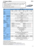
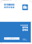
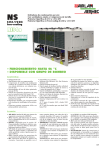
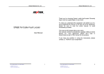
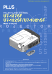
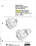
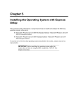
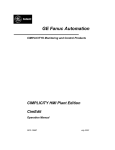
120Rh-1
1.4 Model 120Rh-1
Features
• 1U slim rack-optimized
• Quad-Core Xeon E5405/E5420/X5450/X5460 and Dual-Core Xeon E5205/X5260
• DDR2-667 FB-DIMM memory of up to 48GB with memory mirroring and on-line spare
• Universal hard disk bays supporting up to 900GB SAS and 2.25TB SATA
Model 120Rh-1
MODEL
2.5-inch hard disk drive model
N-code
N8100-1388F
Dual-Core Xeon
E5205
1.86GHz
CPU
Clock
2nd Cache
N8100-1389F
Dual-Core Xeon
X5260
3.33GHz
6MB
No. of CPU
N8100-1390F
Quad-Core Xeon
E5405
2GHz
N8100-1391F
N8100-1438F
Quad-Core Xeon
Quad-Core Xeon
E5420
X5450
2.50GHz
3GHz
2x6MB
1 (standard) - 2 (max.)
Intel® 64
Supported
Chip set
Intel 5000P
1333MHz
1066MHz
Front Side Bus
Memory
Internal
HDD
DDR2-667 FB-DIMM, x4/x8 SDDC, Memory Mirroring, On-line Spare Memory
Standard Capacity
2GB (1GB x2)
Maximum Capacity
48GB (4GB x12) (when standard DIMMs are removed)
Standard Capacity
Diskless
Maximum Capacity
SAS 879GB (146.5GB x 6)
Disk Controller
SAS
RAID *7
RAID 0,1: Standard*1, RAID 5,6: Option
Hot-Plug
Supported
FDD (USB)
Optical disk drive
LAN Interface
Device Bays (3.5") [open]
Disk Drive Bays(2.5”) [open]
Expansion Slots [open]
Graphics
N8100-1392F
Quad-Core Xeon
X5460
3.16GHz
Option*2
CD-RW/DVD-ROM Combo drive*3 x1 (DVD:x8 max. speed, CD: x24 max. speed)
1000BASE-T x2 (100BASE-TX and 10BASE-T are supported) (standard)
- (dedicated for FDD)
6[6]
Full-Height slots
PCI Express (x8) : 1[1] *4
Chip
LowProfile slots
PCI Express (x8) : 1[0] (occupied by RAID controller)
Integrated in the Server Management Controller
VRAM
External Interface
8MB
Serial(D-Sub 9pin) x2 (front x1, fear x1), USB2.0 x6 (front x2, fear x2, internal x2),
1000BASE-T(RJ-45) x2, LAN for Management(100BASE-TX) x1
Display(Mini D-Sub 15pin) x1, Keyboard/Mouse(PS/2) x1*5
Server Management
Server Management Controller (EXPRESSSCOPE Engine 2) is installed as standard.
Power supply
Standard: Not redundant, Option: Redundant
Cooling fan
Redundant (standard)
Keyboard
Option (not included in server as standard)
Mouse
Option (not included in server as standard)
Main unit form
Dimension
(WxDxH)mm
Weight std. (max.)
Consumption power Max.
Standby
Temperature and Humidity Condition
Supported OS
(see chapter of S/W for details)
19inch rack mountable, 1U rack height
425 x 718 x 43
485 x 823 x 43 (when front bezel and the protruding objects are included)
16Kg (20Kg)
600VA/590W
467VA/457W
630VA/620W
630VA/620W
630VA/620W
710VA/700W
474VA/464W
474VA/464W
474VA/464W
486VA/476W
During operation: 10 to 35ºC / 20 to 80% (Non-condensing)
When stored: -10ºC to 55ºC / 20% to 80% (Non-condensing) *6
710VA/ 700W
486VA/ 476W
Windows Server 2003, Standard Edition (SP1 or later) / Enterprise Edition (SP1 pr later)
Windows Server 2003 R2, Standard Edition /Enterprise Edition
Windows Server 2003 R2, Standard x64 Edition / Enterprise x64 Edition
Red Hat Linux *7
*1 On-board RAID is not supported on Linux configuration.
*2 The Internal FDD is not available for 2.5” hard disk drive models.
*3 Writing software is not supported.
*4 2.5-inch hard disk drive models do not provide the Riser Card option.
*5 The keyboard and mouse can be connected together by using a Y cable provided with the main unit.
*6 When stored at a low or high temperature, the system clock may largely deviate from the current time.
*7 Please refer to “Linux on NEC Express5800” (http://www.nec.co.jp/express/linux/index.html)
1-4-1
120Rh-1
Model 120Rh-1
MODEL
3.5-inch hard disk drive model
N-code
N8100-1394F
Dual-Core Xeon
E5205
1.86GHz
CPU
Clock
2nd Cache
N8100-1395F
Dual-Core Xeon
X5260
3.33GHz
6MB
N8100-1396F
Quad-Core Xeon
E5405
2GHz
N8100-1397F
N8100-1439F
Quad-Core Xeon
Quad-Core Xeon
E5420
X5450
2.50GHz
3GHz
2x6MB
1 (standard) - 2 (max.)
No. of CPU
Intel® 64
Supported
Chip set
Intel 5000P
Front Side Bus
1333MHz
1066MHz
Memory
Internal
HDD
DDR2-667 FB-DIMM, x4/x8 SDDC, Memory Mirroring, On-line Spare Memory
Standard Capacity
2GB (1GB x2)
Maximum Capacity
48GB (4GB x12) (when standard DIMMs are removed)
Standard Capacity
Diskless
Maximum Capacity
SATA: 2.25TB (750GB x 3), SAS 900GB (300GB x 3)
SATA / SAS(option)
Disk Controller
RAID *6
RAID 0,1: Standard, RAID 5: Option
Hot-Plug
Supported
FDD (USB)
Optical disk drive
LAN Interface
Device Bays (3.5") [open]
Disk Drive Bays(2.5”) [open]
Expansion Slots [open]
Graphics
N8100-1398F
Quad-Core Xeon
X5460
3.16GHz
Option*1
CD-RW/DVD-ROM Combo drive*2 x1 (DVD:x8 max. speed, CD: x24 max. speed)
1000BASE-T x2 (100BASE-TX and 10BASE-T are supported) (standard)
- (dedicated for FDD)
3[3]
LowProfile slots
PCI Express (x8) : 1[1]
Full-Height slots
PCI Express (x8) : 1[1] *3
Chip
Integrated in the Server Management Controller
8MB
VRAM
External Interface
Serial(D-Sub 9pin) x2 (front x1, rear x1), USB2.0 x4 (front x2, rear x2, internal x2),
1000BASE-T(RJ-45) x2, LAN for Management(100BASE-TX) x1
Display(Mini D-Sub 15pin) x1, Keyboard/Mouse(PS/2) x1*4
Server Management
Server Management Controller (EXPRESSSCOPE Engine 2) is installed as standard.
Power supply
Standard: Not redundant, Option: Redundant
Cooling fan
Redundant (standard)
Keyboard
Option (not included in server as standard)
Mouse
Option (not included in server as standard)
19inch rack mountable, 1U rack height
Main unit form
Dimension
(WxDxH)mm
Weight std. (max.)
Consumption power Max.
Standby
Temperature and Humidity Condition
Supported OS
(see chapter of S/W for details)
425 x 718 x 43
485 x 823 x 43 (when front bezel and the protruding objects are included)
16Kg (20Kg)
600VA/590W
467VA/457W
630VA/620W
630VA/620W
630VA/620W
710VA/700W
474VA/464W
474VA/464W
474VA/464W
486VA/476W
During operation: 10 to 35ºC / 20 to 80% (Non-condensing)
When stored: -10ºC to 55ºC / 20% to 80% (Non-condensing) *5
710VA/ 700W
486VA/ 476W
Windows Server 2003, Standard Edition (SP1 or later) / Enterprise Edition (SP1 pr later)
Windows Server 2003 R2, Standard Edition /Enterprise Edition
Windows Server 2003 R2, Standard x64 Edition / Enterprise x64 Edition
Red Hat Linux *6
*1 The Internal FDD is not available for 2.5” hard disk drive models.
*2 Writing software is not supported.
*3 By replacing the standard riser card with the optional card [N8116-14], one PCI-X 64bit/100MHz slot becomes available instead of a
PCIe (x8) full height slot.
*4 The keyboard and mouse can be connected together by using a Y cable provided with the main unit.
*5 When stored at a low or high temperature, the system clock may largely deviate from the current time.
*6 Please refer to “Linux on NEC Express5800” (http://www.nec.co.jp/express/linux/index.html)
1-4-2
120Rh-1
Model 120Rh-1
MODEL
3.5-inch hard disk drive model (non-redundant power supply)
N-code
CPU
Clock
2nd Cache
N8100-1401F
N8100-1402F
N8100-1405F
Dual-Core Xeon E5205
Dual-Core Xeon X5260
Quad-Core Xeon X5460
3.33GHz
3.16GHz
1.86GHz
6MB
No. of CPU
2x6MB
1 (standard) - 2 (max.)
Intel® 64
Supported
Chip set
Intel 5000P
Front Side Bus
Internal
HDD
1333MHz
1066MHz
Memory
DDR2-667 FB-DIMM, x4/x8 SDDC, Memory Mirroring, On-line Spare Memory
Standard Capacity
2GB (1GB x2)
Maximum Capacity
48GB (4GB x12) (when standard DIMMs are removed)
Standard Capacity
Diskless
Maximum Capacity
SATA: 2.25TB (750GB x 3), SAS 900GB (300GB x 3)
Disk Controller
RAID 0,1: Standard, RAID 5: Option
Hot-Plug
Supported
FDD (USB)
Optical disk drive
LAN Interface
Device Bays (3.5") [open]
Disk Drive Bays(2.5”) [open]
Expansion Slots [open]
Graphics
SATA / SAS (option)
RAID *6
Chip
VRAM
External Interface
Server Management
Power supply
Cooling fan
Option*1
CD-RW/DVD-ROM Combo drive*2 x1 (DVD:x8 max. speed, CD: x24 max. speed)
1000BASE-T x2 (100BASE-TX and 10BASE-T are supported) (standard)
- (dedicated for FDD)
3[3]
Low profile slots
PCI Express (x8): 1[1]
Full-Height slots
PCI Express (x8) : 1[1] *3
Integrated in the Server Management Controller
8MB
Serial(D-Sub 9pin) x2 (front x1, rear x1), USB2.0 x4 (front x2, rear x2, internal x2),
1000BASE-T(RJ-45) x2, LAN for Management(100BASE-TX) x1
Display(Mini D-Sub 15pin) x1, Keyboard/Mouse(PS/2) x1*4
Server Management Controller (EXPRESSSCOPE Engine 2) is installed as standard.
Not redundant
Not redundant
Keyboard
Option (not included in server as standard)
Mouse
Option (not included in server as standard)
Main unit form
Dimension
(WxDxH)mm
Weight std. (max.)
Consumption power Max.
Standby
Temperature and Humidity Condition
Supported OS
(see chapter of S/W for details)
19inch rack mountable, 1U rack height
425 x 718 x 43
485 x 823 x 43 (when front bezel and the protruding objects are included)
16Kg (19Kg)
630VA/620W
600VA/590W
710VA/ 700W
474VA/464W
467VA/457W
During operation: 10 to 35ºC / 20 to 80% (Non-condensing)
When stored: -10ºC to 55ºC / 20% to 80% (Non-condensing) *5
486VA/ 476W
Windows Server 2003, Standard Edition (SP1 or later) / Enterprise Edition (SP1 pr later)
Windows Server 2003 R2, Standard Edition /Enterprise Edition
Windows Server 2003 R2, Standard x64 Edition / Enterprise x64 Edition
Red Hat Linux *6
*1 The Internal FDD is not available for 2.5” hard disk drive models.
*2 Writing software is not supported.
*3 By replacing the standard riser card with the optional card [N8116-14], one PCI-X 64bit/100MHz slot becomes available instead of a
PCIe (x8) full height slot.
*4 The keyboard and mouse can be connected together by using a Y cable provided with the main unit.
*5 When stored at a low or high temperature, the system clock may largely deviate from the current time.
*6 Please refer to “Linux on NEC Express5800” (http://www.nec.co.jp/express/linux/index.html)
1-4-3
120Rh-1
External Design
120Rh-1 (2.5-inch HDD model)
Front View
POWER/SLEEP LED
SERIAL PORT
LAN1 ACCESS LED
USB CONNECTOR
UID LED
DISK ACCESS LED
POWER SWITCH
UID SWITCH
DVD-ROM LAN2 ACCESS STATUS
DRIVE
LED
LED
DUMP
SWITCH
HARD DISK BAYs
Rear View
PCI SLOT
SERIAL PORT
(Low-Profile) CONNECTOR
DUMP SWITCH
PCI SLOT
(Full-Height
AC INLET (option)
USB CONNECTOR
AC INLET
LAN CONNECTOR
DISPLAY CONNECTOR
UID LED
LAN2 CONNECTOR
for
MS/KB CONNECTOR
UID SWITCH LAN1 CONNECTOR
SERVER MANAGEMENT
485
50
773
718
425
484
43
1-4-4
120Rh-1
External Design
120Rh-1 (3.5-inch HDD model)
Front View
POWER/SLEEP LED
SERIAL PORT
LAN1ACCESS LED
USB CONNECTOR
UID LED
POWER SWITCH
UID SWITCH
DVD-ROM DRIVE
FDD BAY
DISK ACCESS LED
STATUS LED
HARD DISK BAYs
LAN2 ACCESS LED
DUMP SWITCH
Rear View
PCI SLOT
SERIAL PORT
(Low-Profile) CONNECTOR
DUMP SWITCH
PCI SLOT
(Full-Height
AC INLET (option)
USB CONNECTOR
AC INLET
LAN CONNECTOR
DISPLAY CONNECTOR
UID LED
LAN2 CONNECTOR
for
MS/KB CONNECTOR
UID SWITCH LAN1 CONNECTOR
SERVER MANAGEMENT
485
50
773
718
425
484
43
1-4-5
120Rh-1
External Design
120Rh-1 (3.5-inch HDD, non-redundant power model)
Front View
POWER/SLEEP LED
SERIAL PORT
LAN1ACCESS LED
USB CONNECTOR
UID LED
POWER SWITCH
UID SWITCH
DVD-ROM DRIVE
FDD BAY
DISK ACCESS LED
STATUS LED
HARD DISK BAYs
LAN2 ACCESS LED
DUMP SWITCH
Rear View
PCI SLOT
SERIAL PORT
(Low-Profile) CONNECTOR
DUMP SWITCH
PCI SLOT
USB CONNECTOR
(Full-Height
AC INLET
LAN CONNECTOR
DISPLAY CONNECTOR
UID LED
LAN2 CONNECTOR
for
MS/KB CONNECTOR
UID SWITCH LAN1 CONNECTOR
SERVER MANAGEMENT
773
718
425
484
50
485
43
1-4-6
Model 120Rh-1
2003
R2
R2x64
EL4
120Rh-1
EL4x64
: Standard
2.5-inch HDD model [N8100-1388F/-1389F/-1390F/-1391F/-1438F/-1392F]
3.5-inch HDD model [N8100-1394F/-1395F/-1396F/-1397F/-1439F/-1398F]
3.5-inch HDD model (non-redundant power/fan) [N8100-1401F/-1402F/-1405F]
: Exclusive
connection
CPU Kit
CPU #1
- CPU Kit (XD/1.86G(6)) [N8101-379] <Dual-Core Xeon E5205>
- CPU Kit (XD/3.33G(6)) [N8101-380] <Dual-Core Xeon X5260>
- CPU Kit (XQ/2G(2x6))
[N8101-381] <Quad-Core Xeon E5405>
- CPU Kit (XQ/2.50G(2x6)) [N8101-382] <Quad-Core Xeon E5420>
- CPU Kit (XQ/3G(2x6))
[N8101-403] <Quad-Core Xeon X5450>
- CPU Kit (XQ/3.16G(2x6)) [N8101-383] <Quad-Core Xeon X5460>
2
CPU #2
* You cannot use
the two slots or
ports at the
same time.
• Do not use processors of different processor numbers at the same time.
Additional Memory Module
- Additional 1GB memory module set [N8102-309] (512MB x2)
- Additional 2GB memory module set [N8102-310] (1GB x2)
- Additional 4GB memory module set [N8102-311] (2GB x2)
- Additional 8GB memory module set [N8102-312] (4GB x2)
1GB DIMM
1GB DIMM
DIMM bank
12
DIMM bank
•
•
•
•
•
•
DIMM bank
DIMM bank
DIMM bank
Each memory module set includes a pair of DIMMs.
Two 1GB DIMMs are factory-installed.
You can expand the memory capacity up to 48GB by replacing the standard DIMMs.
The 120Rh-1 supports x4/x8 SDDC, Memory Mirroring, and On-line Sparing.
DIMM must be inserted from Group #1 toward Group#6 in ascending order.
To enable the memory mirroring and on-line sparing mode, see the next page.
• When you use locally procured non-NEC memory modules, see Chapter 2 Information of
Local Procurement.
Maximum available memory
- See the table below for the maximum memory size that you can actually use on your
system.
- The maximum available memory is less than the maximum physical memory supported
by your system because some chipsets require PCI resource space of about 750MB.
The PCI resource capacity varies by type and number of PCI cards you are using.
Maximum memory size supported by OS
Maximum available memory
(The 120Rh-1 supports up to 48GB.)
4GB
Microsoft Windows Server 2003, Standard Edition (SP1)
Microsoft Windows Server 2003 R2, Standard Edition
4GB
32GB
Microsoft Windows Server 2003, Enterprise Edition (SP1)
Microsoft Windows Server 2003 R2, Enterprise Edition
Microsoft Windows Server 2003 R2, Standard x64 Edition
32GB
128GB
Microsoft Windows Server 2003 R2, Enterprise x64 Edition
48GB
All maximum physical memory
available
16GB
RedHat Enterprise Linux ES4 (x86 / EM64T)
64GB
RedHat Enterprise Linux AS4 (x86)
128GB
RedHat Enterprise Linux AS4 (EM64T)
16GB
48GB
All maximum physical memory
available
48GB
All maximum physical memory
available
1-4-7
120Rh-1
Memory Mirroring / On-line Spare Memory
The 120Rh-1 supports memory mirroring and online spare memory as standard to improve memory reliability.
• Follow the rules for installing memory DIMMs.
• To enable online spare memory, go to BIOS Setup.
• You cannot use the standard memory mode, memory mirroring, and online spare memory at the same time in the same
system.
Memory Mirroring
Mirrored
MB
MB
Memory branch #1
Memory branch #1
In the event
of a memory
failure, a
spare DIMM
takes over a
faulty DIMM
online.
MB
data1
data2
Data3
Configuration
Memory branch #0
データ3
Memory branch #0
データ1
Memory branch #0
On-line Spare Memory
データ2
Standard memory mode
Memory branch #1
Mirrored set
Functions
Not redundant
(default)
Data mirrored between memory branch #0
and #1
Capacity
Same as physical capacity
Half the physical capacity
Hot plug
Not removable during operation
Not removable during operation
Not removable during operation
Reliability
Not redundant
Fully redundant
A faulty DIMM automatically fails over to a
spare memory on the same memory branch.
A faulty DIMM automatically fails over to a
spare memory on the same memory branch.
Physical capacity does not include spare
memory.
Requirements for Online Spare Memory
Requirements for Memory Mirroring
• Memory sizes must be the same across memory groups on the
same memory branch.
• Memory sizes may vary by memory branches.
• The memory groups farthest from the memory branches are spares.
• The branch #0 and #1 must be identical in DIMM configuration
(size and position).
• No mirroring can be configured between the DIMMs on the same
memory branch.
Chipset (Memory Controller)
Group#3
DIMM#12
DIMM#22
=
DIMM#31
Group#4
=
DIMM#32
=
DIMM#33
Group#5
DIMM#13
DIMM#41
DIMM#42
Memory Mirroring
and Online Spare
Memory are not
available at the same
time.
Group#2
Group#3
Group#4
Group#5
Group#6
Group#6
DIMM#23
DIMM#43
Memory combinations for memory mirroring
2GB
:standard
Group#1 Group#2 Group#3 Group#4 Group#5 Group#6 Physical Logical
capacity capacity
2GB
2GB
4GB
2GB
DIMM#11,#21 DIMM#31,#41 DIMM#12,#22 DIMM#32,#42 DIMM#13,#23 DIMM#33,#43
combination1
Group#1
=
Group#2
DIMM#21
MemoryBranch#1
=
Group#1
DIMM#11
MemoryBranch#0
=
The mirrored branch
must have the same
DIMMs in the same
positions as
configured on the
primary branch.
Memory Branch #1
=
Memory Branch #0
Memory combinations for Online Spare Memory
Memory branch #0
Config.
Group#1
Group#2
Group#3
DIMM#A1,#B1
DIMM#A2,#B2
DIMM#A3,#B3
combination2
2GB
2GB
1GB
1GB
6GB
3GB
1
1GB
1GB
combination3
2GB
2GB
2GB
2GB
8GB
4GB
2
1GB
1GB
combination4
2GB
2GB
1GB
1GB
1GB
1GB
8GB
4GB
3
2GB (std.)
2GB
combination5
2GB
2GB
1GB
1GB
2GB
2GB
10GB
5GB
4
2GB (std.)
2GB
combination6
2GB
2GB
2GB
2GB
1GB
1GB
10GB
5GB
5
4GB
4GB
combination7
2GB
2GB
4GB
4GB
12GB
6GB
6
4GB
4GB
combination8
2GB
2GB
2GB
2GB
2GB
2GB
12GB
6GB
7
8GB
8GB
combination9
2GB
2GB
1GB
1GB
4GB
4GB
14GB
7GB
8
8GB
8GB
combination10
2GB
2GB
4GB
4GB
1GB
1GB
14GB
7GB
combination11
2GB
2GB
2GB
2GB
4GB
4GB
16GB
8GB
combination12
2GB
2GB
4GB
4GB
2GB
2GB
16GB
8GB
combination13
2GB
2GB
4GB
4GB
4GB
4GB
20GB
10GB
combination14
4GB
4GB
4GB
4GB
4GB
4GB
24GB
12GB
combination22
8GB
8GB
8GB
8GB
8GB
8GB
48GB
24GB
1GB
2GB
4GB
8GB
Physical
capacity
Logical
capacity
2GB
1GB
3GB
2GB
4GB
3GB
6GB
5GB
8GB
6GB
12GB
10GB
16GB
12GB
24GB
20GB
Your logical memory capacity is calculated using one of the following two formulas:
When you are using 1GB Memory Module Set [N8102
[N8102--309]:
[Logical capacity]
= [Total of physical capacities]
capacities] – [Physical capacity per memory group]
When you are using Standard 1GB memory or
Additional 2GB/4GB//8GB Memory Module Set [N8102-310/-311/-312]:
[Logical capacity]
= [Total of physical capacities] – [Physical capacity per memory group]] / 2
120Rh-1
• A color display, a keyboard and a 2-button mouse are necessary but NOT
provided with the main unit as standard.
Display
Video I/F
1
(PCI/on-board)
1
- Local procurement
(Mini D-sub 15pin)
Keyboard/
Mouse I/F
Keyboard - 104-key keyboard (US-English) [N8170-19]*
Y cable
*provided with
the main unit
(PS/2)
Mouse - 2-button mouse [N8170-15]
*The 104-key Keyboard [N8170-19] cannot be housed in the 19-inch rack
cabinet.
Y cable
*provided with the
main unit
Switch Unit Connection Cable Set (1.8m/3m/5m)
[K410-119(1A)] (1.8m)
[K410-119(03)] (3m)
[K410-119(05)] (5m)
•Up to eight servers can connect directly to the LCD console unit. Use optional Server
Switch Units to connect more than eight servers.
LCD Console Unit
A 17-inch LCD, keyboard, mouse, and Server Switch Unit (x8)
are integrated into the 1U LCD Console Unit.
- 17-inch LCD Console Unit (1U/8port) [N8143-69F]
Consists of the following components:
17-inch LCD
1280x1024 max. Full color
Keyboard
(no ten-key numeric keypad)
Optical Mouse
Server Switch Unit
- Supports up to eight servers.
- Allows the connection of up to 64 servers by cascading the Server Switch
Units [N8191-10F].
Switch Unit Connection Cable Set (1.8m)
[K410-119(1A)]
Server Switch Unit
- Server Switch Unit (8 ports)
[N8191-10F]
•The 17-inch LCD Console Unit [N8143-69F] allows the connection of up to 64 servers
by cascading eight Server Switch Units [N8191-10F].
•The 17-inch LCD Console Unit [N8143-69F] does not support other SSUs [N8191-09F/
-09AF].
1-4-9
120Rh-1
Optical Disk
1 Drive bay
(Internal IDE I/F)
CD-RW/DVD-ROM combo drive (standard)
• Provide either a Built-in or an External FDD for maintenance and OS installation
purpose.
• Automatic System Recovery of Windows Server 2003 operating system and Disaster
Recovery Option of backup software are available for both FDD.
1
Internal USB I/F
FDD
2003
R2
R2x64
EL4
EL4x64
-Internal FDD (USB) [N8151-73A] <slim type, 2-mode>*
USB I/F
4
*[N8151-73A] is not available for 2.5-inch hard disk drive models.
USB I/F
USB I/F
USB I/F
FDD
2003
R2
R2x64
EL4
EL4x64
-External Floppy disk Drive Unit [N8160-74]
• Each of the front and rear panels features two USB ports.
1-4-10
120Rh-1
LAN I/F
(RJ-45)
2
LAN I/F
LAN connection
<1000BASE-T / 100BASE-TX / 10BASE-T>
(RJ-45)
• Standard on-board LAN interfaces can configure AFT/ALB.
• Standard LAN interface and optional LAN board cannot configure AFT/ALB.
(Front panel)
1
Serial I/F
(D-sub 9pin)
(Rear panel)
Serial I/F
1
(D-sub 9pin)
• One serial I/F is on the front panel and the other is on the rear panel.
RS-232C straight cable
- 1.5m [K210-01(01)]
RS-232C devices
- Modem, etc.
UPS
- Local procurement
• One power unit is supplied as standard.
Power Unit
2
(Empty slot)
• To configure hot plug Redundant Power Supply in the 120Rh-1 (except nonredundant models [N8100-1401F/-1402F/-1405F]), use an optional power supply
unit [N8181-50F].
Power Unit - [N8181-50F]
*An empty power unit slot is not provided in N8100-1401F/-1402F/-1405F.
Fans
• The 120Rh-1 (except non-redundant models [N8100-1401F/-1402F/-1405F]) is
equipped with redundant cooling fans as standard.
• Additional cooling fans cannot be installed.
Rack mount option
Cable Arm
- [N8143-70]
• The Cable arm [N8143-70] is used to bundle cables at rear.
• The dimension with the Cable arm [N8143-70] is 485Wx890Dx43Hmm
(including front bezel and protruding objects).
1-4-11
120Rh-1
HDD Configuration
• Choose one configuration from the varieties below.
•The HDD carriers are NOT required for locally purchased non-NEC HDDs as the HDD carriers are
provided with the main unit. See the “Information of Local Procurement” in the Chapter 2 for details.
HDD Configuration (1)
2.5-inch hard disk model
SAS / RAID0,1 / Hot Plug
2003
R2
EL4
EL4x64
HDD Configuration (2)
2.5-inch hard disk model model
SAS / RAID0,1,5,6 / Hot Plug
2003
R2
EL4
EL4x64
R2x64
R2x64
Disk bay
Disk bay
6
Disk bay
Disk bay
Disk bay
Disk bay
HDDs
<2.5-inch SAS HDD>
- 36.3GB HDD (10,000rpm) [N8150-219]
- 73.2GB HDD (10,000rpm) [N8150-220]
- 146.5GB HDD (10,000rpm) [N8150-228]
- 36.3GB HDD (15,000rpm) [N8150-240]
- 73.2GB HDD (15,000rpm) [N8150-241]
The cables are provided
with the main unit.
• Allows up to six HDDs
• Supports RAID0,1
• To configure RAID 5 and 6, a RAID Upgrade Kit [N8103-119] is required.
Inserted to a
PCIe slot
as standard
RAID controller (PCIe card installed in as standard)
<PCIe (x8) RAID 0,1 128MB cache>
Additional DAC Battery
- RAID Battery Backup Unit [N8103-120]
RAID Upgrade Kit
For RAID 5/6 configuration
- [N8103-119]
1-4-12
120Rh-1
HDD Configuration (3)
3.5-inch hard disk model
SATA / non-RAID / non-Hot Plug
2003
R2
R2x64
HDD Configuration (4)
3.5-inch hard disk model
SATA / RAID 0,1 / Hot Plug
2003
R2
R2x64
Disk bay
3
Disk bay
Disk bay
HDDs
<3.5-inch SATA HDD>
- 80GB HDD (7,200rpm)
- 160GB HDD (7,200rpm)
- 250GB HDD (7,200rpm)
- 500GB HDD (7,200rpm)
- 750GB HDD (7,200rpm)
[N8150-207A]
[N8150-208A]
[N8150-209A]
[N8150-229]
[N8150-237]
The cables are provided
with the main unit.
• Allows up to three HDDs
• Supports RAID0,1 (LSI Logic Embedded MegaRAID™)
Internal Serial ATA I/F <Serial ATAII/300>
1-4-13
120Rh-1
HDD Configuration (5)
3.5-inch hard disk model
SAS,SATA / RAID 0,1 / Hot Plug
Disk bay
3
Disk bay
Disk bay
HDDs
R2
EL4
EL4x64
R2x64
The cables are provided
with the main unit.
<3.5-inch SATA HDD>
- 80GB HDD (7,200rpm)
- 160GB HDD (7,200rpm)
- 250GB HDD (7,200rpm)
- 500GB HDD (7,200rpm)
- 750GB HDD (7,200rpm)
HDDs
2003
[N8150-207A]
[N8150-208A]
[N8150-209A]
[N8150-229]
[N8150-237]
<3.5-inch SAS HDD>
- 36.3GB HDD (15,000rpm)
- 73.2GB HDD (15,000rpm)
-146.5GB HDD (15,000rpm)
- 300GB HDD (15,000rpm)
[N8150-199]
[N8150-200]
[N8150-201]
[N8150-226]
• Allows up to three HDDs
Internal SAS I/F
RAID controller
Insert into
PCIe slot
- [N8103-116] <PCIe(x8), RAID 0/1, 128MB cache>
Additional DAC battery
- RAID Battery Backup Unit [N8103-120]
HDD Configuration (6)
3.5-inch hard disk model
SAS,SATA / RAID 0,1,5 / Hot Plug
2003
EL4
R2
R2x64
EL4x64
• Allows up to three HDDs
RAID controller
Insert into
PCIe slot
- [N8103-117] <PCIe(x8), RAID 0/1/5, 128MB cache>
Additional DAC battery
- RAID Battery Backup Unit [N8103-120]
1-4-14
120Rh-1
LAN
PCI slot
-100BASE-TX adapter (PCI) [N8104-111]*
-1000BASE-T adapter (PCI-X) [N8104-119]*
-1000BASE-T adapter (PCI-X) [N8104-120]*
-1000BASE-SX adapter (PCI) [N8104-112]*
-1000BASE-T adapter (PCIe(x1)) [N8104-126]*
-1000BASE-T adapter (PCIe(x4)) [N8104-121]*
-1000BASE-T adapter (PCIe(x4)) [N8104-122]
-10GbE adapter (PCIe(x8)) [N8104-123A]*
2003
R2
EL4
EL4x64
2003
R2
R2x64
LAN
connection
R2x64
* For locally purchased non-NEC LAN adapters,
see the “Information of Local Procurement” in the Chapter 2.
SCSI controller for Device Expansion Unit
2003
R2
EL4
EL4x64
R2x64
- SCSI controller [N8103-95] <Ultra160 SCSI>
- SCSI controller [N8103-75] <Ultra320 SCSI>*
- SCSI controller [N8103-107] <Ultra320 SCSI>*
*You cannot use N8103-75 and N8103-107 at the same time.
- SCSI cable O
[K410-94(01)]
[K410-94(02)]
Device Expansion Unit
See section 1.9 “Device Expansion Unit.“
SAS controller
- [N8103-104]
2003
R2
EL4
EL4x64
Fibre channel controller
- [N8190-127]
- [N8190-131]
2003
R2
EL4
EL4x64
SATA/SAS
Disk Array Unit
R2x64
NEC Storage S Series
Fibre Channel
Disk Array Unit
<1ch, 4Gbps, optical>
<2ch, 4Gbps, optical>
Fibre channel controller
- [N8190-120]
R2x64
2003
R2
EL4
EL4x64
<1ch, 2Gbps, optical>
R2x64
Fibre Channel
Disk Array Unit
See section 1.8 “Disk Expansion Unit.“
Full-Height
Riser Card
Riser Card Variety (Full-Height)
- Standard: PCIe (x8) x1
- [N8116-14]*1: PCI-X 64bit/100MHz x1
*1: The 2.5-inch hard disk drive models do not support the riser card [N8116-14].
1-4-15
120Rh-1
Server Management (EXPRESSSCOPE Engine 2)
On-board
RAS chip
The 120Rh-1 features the EXPRESSSCOPE Engine 2 remote management controller as standard. The
optional Remote KVM and Media License [N8115-03] allows for advanced server management.
Standard
EXPRESSSCOPE Engine 2
•Features a dedicated LAN port
(100BASE-TX/10BASE-T) for
remote sever management
•No PCI slot is required.
SystemGlobe DianaScope 1 license
(or equivalent of [UL1198-001])
•For additional licenses:
SystemGlobe DianaScope 1 license [UL1198-001]
SystemGlobe DianaScope 10 licenses [UL1198-011]
Option
Remote KVM and Media License [N8115-03]
The Remote KVM and Media License enables remote console and remote media features as
the extended functionality of EXPRESSSCOPE Engine 2.
Remote console
Displays a graphics console on the web browser of remote terminals (PC/servers)
Controls remote terminals’ keyboard and mouse via the web browser
Remote media
Provides access to the CD/DVD/FD on the remote terminals (PCs/servers) as if the user were
accessing the drives locally.
120Rh-1 server management functions
EXPRESSSCOPE
Engine 2
EXPRESSSCOPE
Engine 2 with
EXPERSSSCOPE EXPRESSSCOPE Remote KVM and
Engine 2 with
Engine 2
Media License
Remote
KVM
and
+
[N8115-03]
Media License
DianaScope
[N8115-03]
+
DianaScope
Monitoring server
Stole monitoring
/Automatic reboot
Alerting
Monitor temperature /voltage /FAN
/degeneration (CPU/memory)
x
x
x
x
Collecting hardware event log
x
x
x
x
Monitor booting, BIOS/POST stall, OS stall,
shutdown
x
x
x
x
HW err, Boot err and OS panic (by SNMP,EMail) (via LAN)
x
x
x
x
HW err, boot err, and OS panic (via COM port
(modem))
x
x
x
x
POST/BIOS setup, DOS utility
-
x
x
x
Panic screen, Boot screen
x*1
x
x
x
CUI screen (OS console)
x*2
x
x
x
GUI screen (OS console)
-
x
x
x
Remote reset/power on-off/dump
x
x
x
x
OS Shutdown
x
x
x
x
Remote media (CD/DVD/FD) (via LAN)
-
-
x
x
CLP (Command Line Protocol, DMTF
compliant)
x
x
x
x
Remote control via Web browser (not required
dedicated AP)
x
x
x
x
Remote batch
-
x
-
x
Scheduling (not requiring UPS)
-
x
-
x
Maintenance
Remote boot (PXE boot), maintenance
partition boot
x
x
x
x
Others
Automatic IP address setting via DNS/DHCP
x
x
x
x
Remote wakeup
Wake On LAN, Wake On Ring
x
x
x
x
Group management
Monitoring/controlling by the group
-
x
-
x
Industry standard
IPMI
2.0
2.0
2.0
2.0
Remote console
(via COM port/LAN)
Remote controlling
(via COM port/LAN)
Note: all features are independent of OS status.
*1 Boot screen only.
*2 Via COM port only.
120Rh-1
Optional Boards and Adaptable Expansion Slots
3.5-inch hard disk drive models
[N8100-1394F/-1395F/-1396F/-1397F/-1439F/-1398F/-1401F/-1402F/-1405F]
N code
Product name
Slot size
(Full-height or LowProfile)
Supported board type
Installable board size *1
Standard
Standard *2
Option
[N8116-14] *2
PCIe
#1C
x8
PCIe
#1B
x8
PCI-X
#1B
64bit/100MHz
LowProfile
Full-height
Full-height
x8
MD2
x8
Long/Short
3.3V
Long/Short
Note
N8103-95
SCSI controller
(64bit/66MHz PCI)
-
-
O
N8103-75
SCSI controller
(64bit/133MHz PCI-X)
-
-
O
Not for internal HDDs
Do not use with N8103- 107.
N8103-107
SCSI controller
(PCI EXPRESS (x1))
O
O
-
Not for internal HDDs
Do not use w ith N8103-75.
N8103-104
SAS controller
(PCI EXPRESS (x8))
O
O
-
N8103-116
RAID controller (RAID 0/1, 128MB)
(PCI EXPRESS (x8))
-
O
-
N8103-117
RAID controller (RAID 0/1/5/6, 128MB)
(PCI EXPRESS (x8))
-
O
-
N8190-120
Fibre channel controller
(64bit/133MHz PCI-X)
-
-
O
N8190-127
Fibre channel controller (1ch, 4GbFC, LP)
(PCI Express (x4))
O
O
-
N8190-131
Fibre channel controller (2ch, 4GbFC, LP)
(PCI Express (x4))
O
O
-
N8104-111
100BASE-TX adapter
(32bit/33MHz PCI)
1000BASE-T adapter (1port)
(64bit/133MHz PCI-X)
-
-
O
-
-
O
N8104-119
N8104-126
1000BASE-T adapter (PCIe)
(PCI Express (x1))
O
O
-
N8104-120
1000BASE-T (2 port)
(64bit/133MHz PCI-X)
-
-
O
N8104-121
1000BASE-T adapter (2 port)
(PCI Express(x4))
-
O
-
N8104-122
1000BASE-T adapter (2 port)
(PCI-Express (x4))
O
-
-
N8104-112
1000BASE-SX adapter
(64bit/133MHz PCI-X)
-
-
O
N8104-123A
10GbE adapter (1 port)
(PVI Express (x8))
O
O
-
Not for internal HDDs
Not for internal HDDs
Max. 1
*3, *4
*3, *4
*3, *4
Max. 1
*1 Maximum board length
Full Height short: up to 173.1mm long: up to 312mm
Low Profile MD1: up to 119.9mm MD2: up to 167.6mm
*2 By replacing the standard riser card witn an optional Riser Card [N8116-14],
the Full-Height PCI-Express x8 slot becomes a 64bit/100MHz PCI-X slot.
*3 You cannot configure AFT and ALB across two different LAN boards.
*4 10BASE-T is not supported.
Note:
You cannot create an AFT or ALB team across the standard LAN interface and optional LAN board.
1-4-17
120Rh-1
Optional Boards and Adaptable Expansion Slots
2.5-inch hard disk drive models
[N8100-1388F/-1389F/-1390F/-1391F/-1438F/-1392F]
N code
Product name
Slot size
(Full-height or LowProfile)
Supported board type
Installable board size *1
Standard
Standard
PCIe
#1C
x8
PCIe
#1B
x8
LowProfile
Full-height
x8
MD2
x8
Long/Short
-
RAID controller (RAID 0/1, 128MB)
(PCI EXPRESS (x8))
-
O
N8103-107
SCSI controller
(PCI EXPRESS (x1))
O
-
N8103-104
SAS controller
(PCI EXPRESS (x8))
O
-
N8190-127
Fibre channel controller (1ch, 4GbFC, LP)
(PCI Express (x4))
O
-
N8190-131
Fibre channel controller (2ch, 4GbFC, LP)
(PCI Express (x4))
O
-
N8104-126
1000BASE-T adapter (PCIe)
(PCI Express (x1))
O
-
N8104-122
1000BASE-T adapter (2 port)
(PCI-Express (x4))
O
-
N8104-123A
10GbE adapter (1 port)
(PVI Express (x8))
O
-
Note
Installed as standard
Not for internal HDDs
Not for internal HDDs
*2, *3
*2, *3
*1 Maximum board length
Full Height short: up to 173.1mm long: up to 312mm
Low Profile MD1: up to 119.9mm MD2: up to 167.6mm
*2 You cannot configure AFT and ALB across two different LAN boards.
*3 10BASE-T is not supported.
Note:
You cannot create an AFT or ALB team across the standard LAN interface and optional LAN board.
1-4-18
120Rh-1
Adding File Devices
1. Standard Configuration of 3.5-inch hard disk drive models
3.5” Hard Disk
Drive
SATA ID 0
3.5” Hard Disk
Drive
SATA ID 1
3.5” Hard Disk
Drive
SATA ID 2
2. 3.5-inch hard disk drive models with the optional RAID Controller [N8103-116]
3.5” Hard Disk
Drive
SAS/SATA ID 0
3.5” Hard Disk
Drive
SAS/SATA ID 1
3.5” Hard Disk
Drive
SAS/SATA ID 2
1-4-19
120Rh-1
3. Standard Configuration of the 2.5-inch Hard Disk Drive Models
2.5” Hard Disk
Drive
SAS ID 0,1
2.5” Hard Disk
Drive
SAS ID 2,3
RAID Controller (Standard)
2.5” Hard Disk
Drive
SATA ID 4,5
1-4-20