1
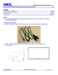
NEC Display Solutions of America, Inc. E324 Installation Guide 32” LCD Display Rev 1.1 Contents Product Description and Notes Ventilation Recommendations Display Dimensions With Stand Front, Top, Right, Left, Bottom Rear Optional Wall Mount Dimensions (WMK-3257) Input Panels Control Codes Page 1 Page 2 Page 3 Page 4 Page 5 Page 6 Page 7 Page 8 Product Description Type: Resolution: Aspect Ratio: FCC: Power Consumption: BTU’s: LCD Display 1366 x 768 16:9 Class B 45W (typ) 153.55 BTU/hour Screen Surface: Anti-Reflective Dimensions without stand: 28.57”(W) x 17.43”(H) x 2.55”(D) Dimensions with stand: 28.57”(W) x 19.59”(H) x 8.43”(D) Weight without stand: 14.8 lbs Weight with stand: 18.5 lbs NOTES: This document is intended to be used as a reference guide to supply useful information for a design or installation. It is not intended to be a step-by step procedure for installation. Any ceilings or walls must be strong enough to support the monitor and the installation must be in accordance with any local building codes. All mounts should make secure contact to wood studs. This unit is built to sustain Landscape orientation only. Distances are in inches, for millimeters multiply by 25.4. Distances may vary ±5%. www.necdisplay.com E324 Page 1 of 8 NEC Display Solutions of America, Inc. E324 Installation Guide 32” LCD Display Rev 1.1 Ventilation Recommendations Dimensions below are minimum recommended for proper ventilation. NOTE: The ventilation space should not be covered or closed off at the front of the opening. If for some reason the opening needs to be covered, other means of ventilation will need to be incorporated into the design. Contact NEC for design review and recommendations. www.necdisplay.com E324 Page 2 of 8 NEC Display Solutions of America, Inc. E324 Installation Guide 32” LCD Display Rev 1.1 Display dimensions with stand attached www.necdisplay.com E324 Page 3 of 8 NEC Display Solutions of America, Inc. E324 Installation Guide 32” LCD Display www.necdisplay.com Rev 1.1 E324 Page 4 of 8 NEC Display Solutions of America, Inc. E324 Installation Guide 32” LCD Display Rev 1.1 Display dimensions 18mm www.necdisplay.com E324 Page 5 of 8 NEC Display Solutions of America, Inc. E324 Installation Guide 32” LCD Display Rev 1.1 Dimensions with optional Wall Mount Kit (WMK-3257) NOTE: Installation of vertical bracket placement can vary. www.necdisplay.com E324 Page 6 of 8 NEC Display Solutions of America, Inc. E324 Installation Guide 32” LCD Display Rev 1.1 Input Panels Back: Side (Rotated): www.necdisplay.com E324 Page 7 of 8 NEC Display Solutions of America, Inc. E324 Installation Guide 32” LCD Display Rev 1.0 Control Codes Function POWER INPUT SWITCH AUDIO MUTE KEY LOCK VGA AUTO SETUP TV CHANNEL Analog Closed Caption Digital Closed Caption ON OFF VGA (15pin HD) HDMI1 HDMI2 HDMI3_________ Video (Composite) TV Video (Component) ON OFF All Buttons Control Buttons Only Unlock Up Down Off CC1 CC2 CC3 CC4 TT1 TT2 TT3 TT4 Off Srv1 Srv2 Srv3 Srv4 Srv5 Srv6 Code Data 01 30 41 30 41 30 43 02 43 32 30 33 44 36 30 30 30 31 03 73 0D 01 30 41 30 41 30 43 02 43 32 30 33 44 36 30 30 30 34 03 76 0D 01 30 41 30 45 30 41 02 30 30 36 30 30 30 30 31 03 73 0D 01 30 41 30 45 30 41 02 30 30 36 30 30 30 31 31 03 72 0D 01 30 41 30 45 30 41 02 30 30 36 30 30 30 31 32 03 71 0D 01 30 41 30 45 30 41 02 30 30 36 30 30 30 31 33 03 70 0D 01 30 41 30 45 30 41 02 30 30 36 30 30 30 30 35 03 77 0D 01 30 41 30 45 30 41 02 30 30 36 30 30 30 30 41 03 03 0D 01 30 41 30 45 30 41 02 30 30 36 30 30 30 30 43 03 01 0D 01 30 41 30 45 30 41 02 30 30 38 44 30 30 30 31 03 09 0D 01 30 41 30 45 30 41 02 30 30 38 44 30 30 30 32 03 0A 0D 01 30 41 30 45 30 41 02 30 30 46 42 30 30 30 32 03 72 0D 01 30 41 30 45 30 41 02 30 30 46 42 30 30 30 31 03 71 0D 01 30 41 30 45 30 41 02 30 30 46 42 30 30 30 30 03 70 0D 01 30 41 30 45 30 41 02 30 30 31 45 30 30 30 31 03 01 0D 01 30 41 30 45 30 41 02 30 30 38 42 30 30 30 31 03 0F 0D 01 30 41 30 45 30 41 02 30 30 38 42 30 30 30 32 03 0C 0D 01 30 41 30 45 30 41 02 31 30 38 34 30 30 30 31 03 78 0D 01 30 41 30 45 30 41 02 31 30 38 34 30 30 30 32 03 7B 0D 01 30 41 30 45 30 41 02 31 30 38 34 30 30 30 33 03 7A 0D 01 30 41 30 45 30 41 02 31 30 38 34 30 30 30 34 03 7D 0D 01 30 41 30 45 30 41 02 31 30 38 34 30 30 30 35 03 7C 0D 01 30 41 30 45 30 41 02 31 30 38 34 30 30 30 36 03 7F 0D 01 30 41 30 45 30 41 02 31 30 38 34 30 30 30 37 03 7E 0D 01 30 41 30 45 30 41 02 31 30 38 34 30 30 30 38 03 71 0D 01 30 41 30 45 30 41 02 31 30 38 34 30 30 30 39 03 70 0D 01 30 41 30 45 30 41 02 31 30 41 31 30 30 30 31 03 04 0D 01 30 41 30 45 30 41 02 31 30 41 31 30 30 30 32 03 07 0D 01 30 41 30 45 30 41 02 31 30 41 31 30 30 30 33 03 06 0D 01 30 41 30 45 30 41 02 31 30 41 31 30 30 30 34 03 01 0D 01 30 41 30 45 30 41 02 31 30 41 31 30 30 30 35 03 00 0D 01 30 41 30 45 30 41 02 31 30 41 31 30 30 30 36 03 03 0D 01 30 41 30 45 30 41 02 31 30 41 31 30 30 30 37 03 02 0D NOTE: The above list contains most of the compatible external communication codes for the E324. Cable Connection PC Control Connector (D-Sub 9P) Communication Interface NOTE: If so desired, jumper “Request to send” and “Clear to Send” together on both ends of the cable to simplify cable connection. These connections are not required. The only connections required are pins 2 (TxD), 3 (RxD) and 5 (GND). NOTE: Communication for the E324 is not bidirectional. The display will only accept commands and will not send feedback. www.necdisplay.com E324 Page 8 of 8