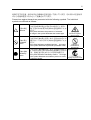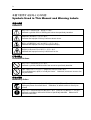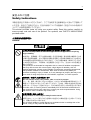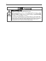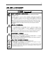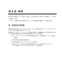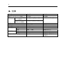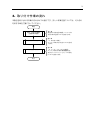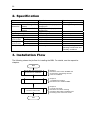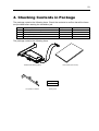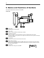
1
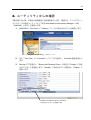
Keep this manual carefully. N8103-102 Additional DAC Battery User's Guide • • Make sure you read this manual before using the product. After reading this manual carefully, store it in a safe place. 855-900502-011-A Microsoft Windows PromiseTechnology, Inc. Array Management WebPAM MS MS-DOS SuperTrak Promise Microsoft TM SuperBuild Utility Web-based Promise Trademarks Microsoft, its logo, Windows, Windows Server and MS-DOS are worldwide registered trademarks of Microsoft Corporation of the U.S.A. Promise Technology, Inc., its logo, SuperTrak, SuperBuildTM Utility, and Web-based Promise Array Manager (WebPAM) are registered trademarks of Promise Technology Inc. of the U.S.A. All company names and product names mentioned herein are trademarks or registered trademarks of their respective companies. (1) (2) (3) (4) (5) (6) Notes: (1) (2) (3) (4) (5) (6) No part of this manual may be reproduced in any form without the prior written permission of NEC Corporation. The contents of this manual may be revised without prior notice. The contents of this manual shall not be copied or altered without the prior written permission of NEC Corporation. All efforts have been made to ensure the accuracy of all information in this manual. If you notice any part unclear, incorrect, or omitted in this manual, contact the sales agent where you purchased this product. NEC assumes no liability arising from the use of this product, nor any liability for incidental or consequential damages arising from the use of this manual regardless of Item (4). If you find any missing pages or pages out of order in this manual, please contact your dealer for a replacement. Preface N8103-102 ( ) N8103-101 N8103-101 (SATA2) (SATA2) i i xviii 21 20 38 Congratulations for your purchase of the N8103-102 Additional DAC Battery (called BBU hereafter). The User’s Guide describes how to install and use the BBU correctly and safely. Read the guide thoroughly before handling it. In addition, refer to this manual when you want to know how to use it or some malfunction occurs. Always keep the manual at hand so that you can see it as soon as possible if necessary. For the N8103-101 Disk Array Controller (SATA2) to which the BBU is connected, refer to the User’s Guide coming with the disk array controller. Read "Notes on Use" carefully before handling the BBU. This User's Guide is written in both Japanese and English. For Japanese, refer to pages i to 20. For English, refer to pages i to xviii and 21 to 38. ii Keep this User's Guide at hand for quick reference at anytime necessary. Be sure to read this section carefully. NOTES ON USE - Always read the Notes - The following includes information necessary for proper and safe operation of the product. SAFETY INDICATIONS In the User’s Guide, "WARNING" or "CAUTION" is used to indicate a degree of danger. These terms are defined as follows: WARNING Indicates the presence of a hazard that may result in death or serious personal injury. CAUTION Indicates the presence of a hazard that may cause minor personal injury, including burns, or property damage. iii Precautions against hazards are presented with the following symbols. The individual symbols are defined as follows: ( Attention This symbol indicates the presence of a hazard. An image in the symbol illustrates the hazard type. ( ) (Example) ( This symbol indicates prohibited actions. An image in the symbol illustrates a particular prohibited action. This symbol indicates mandatory actions. An image in the symbol illustrates a mandatory action to avoid a particular hazard. ) Prohibition of disassembly ( Mandatory Action ) Precaution against electric shock ( Prohibited Action ) (Example) ) (Example) ( ) Unplug the power cord! iv Symbols Used in This Manual and Warning Labels Attentions Indicates a general notice or warning that cannot be specifically identified. Indicates that improper use may cause an electric shock. Indicates that improper use may cause personal injury. Indicates that improper use may cause fumes or fire. Prohibited Actions Indicates a general prohibited action that cannot be specifically identified. Do not disassemble, repair, or modify the server. Otherwise, an electric shock or fire may be caused. Mandatory Action Unplug the power cord of the server. caused. Otherwise, an electric shock or fire may be Indicates a mandatory action that cannot be specifically identified. follow the instruction. Make sure to v Safety Indications This section provides notes on using your product safely. Read this section carefully to ensure proper and safe use of the product. For symbols, see "SAFETY INDICATIONS" provided earlier. General WARNING Do not use the product in life-critical applications or applications requiring high reliability. The product is not intended for integration with or control of facilities or equipment that may affect human life or that require a high degree of reliability, such as medical equipment, nuclear power facilities or instruments, aerospace instruments, transportation facilities or instruments. NEC does not assume any liability for accidents resulting in injury or death, or for any damages to property that may occur as a result of using the product in such facilities, equipment, or control systems. Do not use the server if any smoke, odor, or noise is present. OFF AC If smoke, odor, or noise is present, immediately turn off the server and disconnect the power plug from the AC outlet, then contact your service representative. Using the server in such conditions may cause a fire. Keep needles or metal objects away from the server. Do not insert needles or metal objects into ventilation holes or cartridge slot of the server. Doing so may cause an electric shock. vi CAUTION Keep water or foreign matter away from the server. OFF AC Do not let any form of liquid (water etc.) or foreign matter (e.g., pins or paper clips) enter the server. Failure to follow this warning may cause an electric shock, a fire, or a failure of the server. When such things accidentally enter the server, immediately turn off the power and disconnect the power plug from the AC outlet. Do not disassemble the server. Contact your service representative. vii Power Supply and Power Cord Use CAUTION ON Disconnect the power cord(s) before installing or removing the product in/from the server. AC AC Make sure to power off the server and disconnect the power cord(s) from a power outlet before installing/removing the product in/from the server, or connecting with the peripheral devices. All voltage is removed only when the power cords are unplugged. Do not use any damaged cable. Make sure the cable condition before connection. Using the damaged connector, bent connector pin, or dirty connector may cause a fire due to short-circuit. Do not hold the power plug with a wet hand. Do not disconnect/connect the plug while your hands are wet. Failure to follow this warning may cause an electric shock. Do not pull the cable when disconnecting the power cord. When disconnecting the power cord from the server, hold the plug and pull it straight out. Pulling the cord out by the cable portion could damage the cable to result in an electrical shock hazard or a fire. viii Installation, Relocation, Storage, and Connection CAUTION Do not connect any interface cable with the power cord of the server plugged to a power source. OFF Make sure to power off the server and unplug the power cord from a power outlet before connecting/disconnecting any interface cable to/from the server. If the server is off-powered but its power cord is plugged to a power source, touching a cable or connector may cause an electric shock or a fire resulted from a short circuit. Do not use any unauthorized interface cable. NEC Use only interface cables authorized by NEC and locate a proper device and connector before connecting a cable. Using an unauthorized cable or connecting a cable to an improper destination may cause a short circuit, resulting in a fire. Also, observe the following notes on using and connecting an interface cable. Do not step on the cable. Do not place any object on the cable. Do not use the server with loose cable connections. Do not use any damaged cable connector. Make sure the cable is securely locked with screw. ix CAUTION Do not use or store the product in the place where corrosive gases exist. Make sure not to locate or use the server in the place where corrosive gases (sulfur dioxide, hydrogen sulfide, nitrogen dioxide, chlorine, ammonia, ozone, etc) exist. Also, do not install it in the environment where the air (or dust) includes components accelerating corrosion (ex. sulfur, sodium chloride) or conductive metals. There is a risk of a fire due to corrosion and shorts of an internal printed board. Consult with your service representative for the location appropriate to the server. Avoid installation in extreme temperature conditions. OFF / Immediately after the server is powered off, its internal components such as hard disk drives are very hot. Leave the server until its internal components fully cool down before installing/removing any component. x Cleaning and Working with the Product WARNING Do not disassemble, repair, or alter the server. Never attempt to disassemble, repair, or alter the product on any occasion. Failure to follow this instruction may cause an electric shock or fire as well as malfunctions of the product. Disconnect the power plug before accessing inside the server. OFF AC OFF Make sure to power off the server and disconnect the power plug from a AC outlet before accessing inside the server. Touching any internal device of the server with its power cord connected to a power source may cause an electric shock even if the server is off-powered. CAUTION Make sure to complete installation. DC Always connect the DC cable and/or interface cable firmly. An incompletely connected cable may cause a contact failure, resulting in smoking or fire. xi During Operation CAUTION Avoid contact with the server during thunderstorms. Disconnect the power plug from the outlet when a thunderstorm is approaching. If it starts thundering before you disconnect the power plug, do not touch any part of the server containing the product. Failure to follow this warning may cause an electric shock. Keep animals away from the server. Keep animals away from the server containing the product. Pet's discharges or fur may enter the server and cause a fire or electric shock. Do not use a cellular phone or a pager around the server. PHS OFF Turn off the cellular phone or pager near the server containing the product. Radio interference may cause malfunctions of the server. xii Warning Labels The warning label is attached to the product with possible danger or their vicinity in your product to inform the user that a hazardous situation may arise when operating the product. (Do not intentionally remove or damage any of the labels.) If you find any labels totally/partially removed or illegible due to damage, contact your sales representative. xiii Notes on Use - for correct operation of BBU ( N8103-101 ) (SATA2) Note the following when you use the BBU. If you ignore the notes, your assets (including important data and/or other devices) may be damaged. The BBU is an additional battery exclusively used for the N8103-101 Disk Array Controller (SATA2). The BBU cannot be connected to any other disk array controllers. The BBU is an extremely sensitive electronic device. First make your body contact with metallic frame of the server to discharge static electricity from your body before handling the BBU. Do not drop the BBU. Do not make the BBU hit against other objects. For the recycle and disposal of the BBU, see "Recycle and Disposal" in this chapter. xiv This Manual Windows The guide is intended for persons who are familiar with operating systems including Windows and fundamental operations of general-purpose I/O devices including the keyboard and mouse. Text Conventions The following conventions are used throughout this User's Guide. For safety symbols, see "SAFETY INDICATIONS" provided earlier. Notice Items to be observed or points to be noted when operating the product. Items to be checked when operating the product Check Information useful or convenient for you Tips xv In the Package The carton contains various accessories, as well as the product itself. See the packing list to make sure that you have everything and that individual components are not damaged. If you find any component missing or damaged, contact your sales agent. Transportation 1 To transport the BBU, remove it from the server following "Chapter 1 Overview" and put the BBU and all the accessories in the package used for the delivery. xvi Transfer to Third Party Make sure to provide this manual along with the product to a third party. HDD HDD ( ) Windows Linux HDD Notice ( ( ) ) About data on the hard disk Be sure to take appropriate measures not to leak important data (e.g., customers' information or companies' management information) on the removed hard disk to any third parties. Data seems to be erased when you empty "Recycle Bin" of Windows or execute the "format" command of the operating system. However, the actual data remains written on the hard disk. Data not erased completely may be restored by special software and used for unexpected purposes. It is strongly recommended that the software or service (both available at stores) for data erasure should be used in order to avoid the trouble explained above. For details on data erasure, ask your sales representative. NEC assumes no liability for data leakage if the product is transferred to third party without erasing the data. xvii Life of BBU 2 2 ( ) NEC The BBU is equipped with a backup battery. The life of the battery is about 2 years while it varies depending on the use environment and operating conditions. Replace the battery with a new one after about two years from the installation of the BBU (the installation time can be known by the battery label put on the server and the BBU). Contact your service representative for the replacement Maintenance Parts 5 The holding period of maintenance parts of the BBU is five years from the truncation of manufacturing. xviii Recycle and Disposal NEC 3 4. NEC 3 The battery pack of the BBU is equipped with lithium ion battery which is recyclable. To enable such valuable resources to be reused, contact your service representative or bring it to the nearest recycle agent. For the removal of the BBU, see "4. Battery Pack Replacement Procedure" in "Chapter 3 Operation and Maintenance". Dispose of other devices following the regulation of the local government. For details, contact the local government or your service representative. Take sufficient note on the handling of the battery pack following "Chapter 3 Operation and Maintenance". (CD-R/CD-RW) Notice Dispose of hard disk drives, backup data cartridges, floppy disks and other writable media (including CD-R/CD-RW) after erasing the data saved in the media securely on your own responsibility so that the data may not be restored, replayed, and/or reused by third parties. Take special care for protecting individual privacy and corporate secret. xix Preface ......................................................................................................................... i NOTES ON USE - Always read the Notes - .............................................................. ii Symbols Used in This Manual and Warning Labels ................ iv Safety Indications.............................................................................................. v Warning Labels .........................................................................................xii Notes on Use - for correct operation of BBU - ......................................................................xiii This Manual ........................................................................................................xiv In the Package ..................................................................................... xv Transportation..................................................................................................... xv Transfer to Third Party ......................................................................xvi Life of BBU .................................................................................................xvii Maintenance Parts ..................................................................................xvii Recycle and Disposal.................................................................. xviii ........................................................................................................................................xix 1 ......................................................................................................................... 1 1. 2. 3. 4. 5. 6. ............................................................................................................................... 1 ............................................................................................................................................. 2 .................................................................................................................... 3 ............................................................................................................. 4 ........................................................................................................................ 5 ...................................................................................................................................... 7 6-1. ......................................................................................................... 7 6-2. ................................................................................................................ 7 2 ................................................................................................... 9 1. 2. ............................................................................................................................... 9 .............................................................................................................. 9 ............................................................................................ 10 ................................................................................................ 10 ................................................................................................... 11 .............................................................................................................. 11 ....................................................................................................... 13 3 ............................................................................................................ 15 1. 2. ............................................................................................................................. 15 .................................................................................................................................... 15 .............................................................................................................. 15 ....................................................................................................... 15 ....................................................................................................... 16 1-1. PCI 1-2. 1-3. 1-4. 1-5. 2-1. 2-2. 3. xx Contents Chapter 1 Overview ........................................................................................................... 21 1. Characteristics of BBU ............................................................................................................... 21 2. Specification ............................................................................................................................... 22 3. Installation Flow ......................................................................................................................... 22 4. Checking Contents in Package .................................................................................................. 23 5. Names and Functions of Sections.............................................................................................. 24 6. Notes.......................................................................................................................................... 26 6-1. Notes on Installation ........................................................................................................... 26 6-2. Notes on Operation ............................................................................................................ 26 Chapter 2 Installing BBU.................................................................................................... 27 1. Installation Procedure................................................................................................................. 27 1-1. Selecting PCI Slot............................................................................................................... 27 1-2. Selecting and Installing Bracket.......................................................................................... 28 1-3. Putting Battery Label .......................................................................................................... 29 1-4. Removing Side Cover on Server ........................................................................................ 29 1-5. Installing BBU in Server...................................................................................................... 30 2. Checking by Utility...................................................................................................................... 32 Chapter 3 Operation and Maintenance .............................................................................. 33 1. Maintenance Service.................................................................................................................. 33 2. Preventive Maintenance............................................................................................................. 33 2-1. Preventive Maintenance of BBU......................................................................................... 33 2-2. Life of Battery Pack............................................................................................................. 33 3. Battery Pack Replacement Procedure ....................................................................................... 34 1 N8103-102 ( ) 1. N8103-101 ) (Write Back ) SDRAM 72 (SATA2)( ( ) Write Back PCI PCI-Express PCI/PCI-X 2 2. 72 121( PCI PCI 81( )×120( )×120( 0.10(kg) 3.7(V) 1.92(W) ( ) 10°C 20% 0°C 20% 2 35°C 80% 35°C 80% )X22( )X22( )mm )mm 3 3. 1 2 1. 2 2. 4 4. 1 2 3 4 5 1 1 1 1 1 PCI Set up Date Y PCI .M 5 5. 2 6 5 3 1 4 1 2 3 PCI PCI (PCI/PCI-X PCI-Express ) PCI PCI 4 PCI PCI 5 2 6 N8103-102 6 8 9 Set up Date Y .M 7 7 XX X 8 PCI ( ) PCI PCI 9 ( ) ( ) PCI 7 6. 6-1. PCI 1 PCI 6-2. 2 2 NEC Web-based Promise Array Manager( WebPAM ) Battery voltage is out of range WebPAM ) ( 8 2 1. 1-1. PCI PCI PCI-Express PCI/PCI-X PCI PCI PCI PCI PCI/PCI-X 1. 1-2. PCI-Express PCI (2 2. PCI 1 PCI/PCI-X (2 ) PCI-E PCI-E PCI-E PCI-E PCI-Express ) PCI/PCI-X 10 1-2. PCI PCI PCI 1. PCI 2. PCI (2 3. PCI 4. PCI 1 ) (2 ) PCI PCI 1-3. ( Set up Date Y Y 2006 M ) PCI 5 .M 2 2 (72 3 ) 11 1-4. OFF 1-5. 1. PCI 2. 2 12 3. PCI PCI PCI 4. 1 13 2. Web-based Promise Array Manager WebPAM 1. WebPAM Tree View Battery Battery 2. 3. Tree View Settings Controller 1 Controller Battery Not Detected Event Disable Battery Not Detected Event Enable Enable Enable 14 4. Logical Drive View Information 5. Setting Logical Drive Logical Drive (Write Cache Mode ) AutoSwitch 6. (Write Cache Status ) Write Back WebPAM Voltage Now Reading... ( 6 WebPAM ) WebPAM WebPAM CD-ROM ( ) 3 1. NEC NEC 2. 2-1. ( ) Web-based Promise Array Manager( WebPAM ) 2-2. 2 3. / 2 16 3. 1. 2. OS OFF 3. 4. 5. 6. ( ) 7. (4 ) 17 8. 9. 10. 18 11. 12. 7 (4 ) 19 13. ( ) PCI Set up Date Y Y 2006 M 5 .M 14. ( ) 2 20 15. PCI 16. 17. ON 18. OS 2 2. WebPAM Voltage Now Reading. . ( 6 WebPAM ) WebPAM NEC Chapter 1 Overview First read this chapter if you use the N8103-102 Additional DAC Battery (called BBU hereafter) for the first time. This chapter describes the characteristics and configuration of the BBU and outlines the additional battery installation job. 1. Characteristics of BBU The BBU is an additional battery exclusively used for the N8103-101 Disk Array Controller (SATA2) (called disk array controller hereafter). Connecting the BBU to the disk array controller can prevent data from being lost due to an accident including instantaneous power interruption (in the WriteBack mode). Backup of data in SDRAMs on disk array controller for up to 72 hours Improvement of reliability in WriteBack mode Use of rechargeable lithium ion battery Can be installed in either of PCI/PCI-X slot or PCI-Express slot by changing the installation position of PCI bracket. 22 2. Specification Item Maximum data backup time Outer Use of full-height PCI dimension bracket Use of low-profile PCI bracket Weight Operating voltage Power consumption Operating Temperature environment Humidity Storage Temperature environment Humidity Life (battery back) Specification 72 hours 121 (width) × 120 (depth) x 22 (height) mm 81 (width) × 120 (depth) x 22 (height) mm Approx. 0.10 kg 3.7 V or higher 1.92 W 10°C to 35°C 20% to 80% 0°C to 35°C 20% to 80% About 2 years Remarks Full charging Excluding battery cable In normal operation Without condensation Without condensation Varies depending on operating environment and boundary conditions 3. Installation Flow The following shows the job flow for installing the BBU. For details, see the respective chapters. Start Check BBU and accessories. Check notes on installation. Install BBU. Check connections and set write cache mode. End Chapter 1 Describes how to check the BBU and accessories in the package and the notes on installation. Chapter 2 1. Installation Procedure Describes how to install the BBU. Chapter 2 2. Check from Utility Describes connection checking procedure after battery installation and the setting of the write cache mode. 23 4. Checking Contents in Package The package contains the following items. Check the contents to confirm that all the items are provided before starting the installation job. No. 1 2 3 4 Item Additional DAC battery User’s Guide Battery label Low-profile PCI bracket Qty 1 1 1 1 Remarks This unit This manual The package contains the following items. User’s Guide (this manual) Additional DAC Battery (BBU) Set up Date Y Low-profile PCI bracket .M Battery label 24 5. Names and Functions of Sections This section describes the sections of the BBU. Front view 2 6 3 5 1 4 1 Battery case Contains lithium ion battery pack. 2 Battery cable Used to connect the BBU to the disk array controller. 3 Full-height PCI bracket Used to fix the BBU to a PCI slot (PCI/PCI-X slot or PCI-Express slot) of the server. To install the BBU to a low-profile PCI slot, replace the bracket with the low-profile PCI bracket coming with the BBU. 4 PCI connector Insert the PCI connector into a PCI slot of the server. 5 Battery cable connectors Used to connect the battery cable to the BBU. Either of two connectors may be used. Select either connector appropriate to your system environment (e.g., location to install in the server and cable routing condition). 6 N code label Indicates the N code given for this BBU. N8103-102 25 Rear view Accessories 8 9 Set up Date Y .M 7 7 Recycle label The label is put on the BBU. It indicates the recycle mark, battery type, and warning, and is filled with the management revision of the BBU. NOTE: The recycle label is also put on the battery pack in the battery case. The label on the battery pack is filled with the management revision of the battery pack. The management revision may differ from that on the recycle label put on the rear face of the BBU, but it is no problem. XX X 8 Low-profile PCI bracket (accessory) Used to install the BBU to a low-profile PCI slot. Replace the factory-installed full-height PCI bracket with the low-profile bracket if necessary. 9 Battery label (accessory) The label comes with the BBU. Fill the date (year and month) when the BBU is installed in the server. Then put the label on the PCI bracket of the BBU. 26 6. Notes Read the following notes thoroughly before using the BBU. 6-1. Notes on Installation Do not put the BBU on a metallic plate including the chassis of the server. Do not hold the BBU with wet hands. If you do not follow these directions, the battery may be short-circuited. To install the BBU in the server, a single PCI slot of the server must be used. Before starting the installation, make sure that a PCI slot remains unused. 6-2. Notes on Operation The life of the battery pack used for the BBU is about 2 years, which may vary a little depending on the use environment and environmental conditions. Replace the battery pack with a new one after about two years from the installation. For the replacement, contact your service representative. To manage the states of the BBU properly, install the Disk Array Controller Management Utility "Web-based Promise Array Manager" (called WebPAM hereafter). WebPAM allows you to detect errors and check the states of the BBU (including voltage and temperature). The following alert may be logged when you restart the system immediately after charged the BBU, however, you can ignore it. If you continue to charge the BBU, the alert will no longer be logged. "Battery voltage is out of range" Chapter 2 Installing BBU This chapter describes the installation of the BBU in the server. 1. Installation Procedure Install the BBU in the disk array controller in the following procedure. Before starting the installation job, refer to the User’s Guide of the disk array controller and that of the server. Check 1-1. Selecting PCI Slot By changing the PCI bracket position, the BBU may be installed in either of PCI/PCI-X slot or PCI-Express slot on the server. Select an appropriate PCI slot to install the BBU among the unused slots. To install the BBU in the low-profile PCI slot, you need to replace the PCI bracket. See the subsequent section "Selecting and Installing Bracket" for details. The factory installed PCI bracket is for PCI-Express slot. To install the BBU in PCI/PCI-X slot, take the following procedure. 1. Remove the two screws fixing the BBU with PCI bracket. 2. Locate screw positions to the non-marked places (PCI/PCI-X slot side), and fix the PCI bracket with the two screws removed in Step 1. PCI-E PCI-E PCI-E PCI-E PCI-Express slot side PCI/PCI-X slot side 28 1-2. Selecting and Installing Bracket The BBU is originally equipped with the full-height PCI bracket. To install the BBU to a low-profile PCI slot, the full-height PCI bracket must be replaced with the low-profile PCI bracket coming with the BBU. 1. Remove the screws (2) fixing the full-height PCI bracket to the BBU. 2. Remove the full-height PCI bracket. 3. Install the low-profile PCI bracket. 4. Fix the low-profile PCI bracket to the BBU with the screws (2) removed in step 1. Full-height PCI bracket Low-profile PCI bracket 29 1-3. Putting Battery Label Fill the date (year and month) when the BBU is installed in the server on the battery label coming with the BBU. Then put the label on the PCI bracket. Fill the year and month. Set up Date Y Notice Example) Y 2006 M 5 .M The life of the battery is about 2 years while it varies depending on the use environment and operating conditions. If the battery pack is used after its life, the maximum data backup time (72 hours) cannot be secured. Replace such a battery pack with a new one as soon as possible following "Chapter 3 Operation and Maintenance". 1-4. Removing Side Cover on Server Remove the side cover on the server following the User’s Guide of the server. Before removing the side cover, turn off the power of the server and remove all the power cords connected to the power unit from the receptacles. 30 1-5. Installing BBU in Server Install the BBU in the disk array controller and the server in the following procedure: 1. Remove the additional slot cover and screw from an unused PCI slot. Remove the cables from the disk array controller. 2. Remove the disk array controller from the server, and connect the battery cable to the battery connector on the disk array controller. NOTE: The BBU has two battery cable connectors. Either of two connectors may be used. Select either connector appropriate to your system environment (e.g., location to install in the server and cable routing condition) to connect the battery cable. 31 3. Insert the BBU and disk array controller into the PCI slot and fix the BBU with the screw removed previously. Screw Disk array controller Screws BBU Battery cable To install the BBU in the server, an empty PCI slot is required in the server. Before the installation, make sure that at least one unused PCI slot remains in the server. Notice 4. Install the side cover on the server. Connect the cable to the disk array controller and power cord to the receptacles to recover the original state. 32 2. Checking by Utility After the installation, check the connections and settings of the BBU using the disk array controller management utility "Web-based Promise Array Manager" (called WebPAM hereafter). 1. Make sure that the Battery icon appears in the Tree View of WebPAM. "Battery" icon 2. Select the controller 1 icon in the Tree View to open the Controller screen. 3. Select the Setting tab to make sure that Battery Not Detected Event is set to “Enable”. If it is set to "Disable", change to "Enable". 4. Select each logical drive under the Logical Drive View to open the Logical Drive Information screen. 5. Select the Setting tab to make sure that the Write Cache Mode (setting write cache operation) is set to "AutoSwitch". 6. After charging the BBU, make sure that the Write Cache Status (indicating the current write cache operation status) is set to "Write Back". The battery pack contained in the shipping package is not charged at all. Notice For such battery pack, the value of "Voltage" is indicated as "Now Reading..." on WebPAM. WebPAM may not able to recognize the battery pack if it is charged only at the minimum level (or uncharged). If this occurs, charge the battery pack for six hours or longer. Then reboot the server and try to recognize the battery pack again by using WebPAM. For details of the write cache mode, refer to the User’s Guide of the disk array controller or WebPAM User’s Guide (online document in the CD-ROM coming with the disk array controller). Tips Chapter 3 Operation and Maintenance 1. Maintenance Service Service representatives subordinate to or authorized by NEC provide services of the BBU with use of genuine parts and high technical capabilities. You can get the services for your own convenience. For the services, contact the NEC sales department or representatives. 2. Preventive Maintenance 2-1. Preventive Maintenance of BBU Check the states of the BBU (including voltage and temperature) regularly as preventive maintenance. For the purpose, you can use WebPAM. 2-2. Life of Battery Pack The battery pack used in the BBU can be used for about two years. Replace the battery pack having been used for two years or longer with a new one as soon as possible following "3. Battery Pack Replacement Procedure" in this chapter. The battery pack is a supply/charged warranty device. Notice 34 3. Battery Pack Replacement Procedure Replace the battery pack in the following procedure: 1. Exit from all applications and shutdown OS. 2. Turn off the power of the server and remove all the power cords connected to the power unit from the receptacles. 3. Remove the side cover following the User’s Guide of the server. 4. Remove all the cables from the disk array controller and the server. 5. Remove the screw fixing the BBU and the disk array controller. Then remove the BBU and the disk array controller from the server. 6. Remove the battery cable, which connect the BBU with the disk array controller, from the disk array controller. 7. On the rear face of the BBU, remove the screws (4) fixing he battery case. 35 8. Remove the battery pack cable from the battery case connector. 9. Remove the battery pack from the battery case. Battery pack Battery case 10. Replace the battery pack with a new one and install it to the battery case. New (replaced) battery pack Battery case 36 11. Connect the battery pack cable to the connector on the battery case. Make sure that the connector pins of the battery pack cable are securely inserted into the battery case connector. New (replaced) battery pack Battery case 12. On the rear face of the BBU, fix the battery pack with the screws (4) removed in step 7. 37 13. Fill the replacement date (year and month) on the battery label coming with the battery pack. Then put the label on the PCI bracket. The old label may be either peeled off or left. If left, put the new label on the old one. Fill the year and month. Set up Date Y 14. Example) Y 2006 M 5 .M Connect the battery connector of the BBU to that of the disk array controller with battery cable. NOTE: The BBU has two battery cable connectors. Either of two connectors may be used. Select either connector appropriate to your system environment (e.g., location to install in the server and cable routing condition) to connect the battery cable. 38 15. Install the BBU and the disk array controller to the PCI slot of the server as before and fix it with the screw. Disk array controller Screws BBU Battery cable 16. Connect all the cables to the server and the disk array controller as before. 17. Install the removed side cover and power cords to recover the original state. Turn on the power of the server. 18. After OS is booted, check whether the BBU is recognized correctly. For the checking procedure, see "2. Checking by Utility" in "Chapter 2 Installation of BBU". The battery pack provided as a maintenance part is not charged at all. For Notice such battery pack, the value of "Voltage" is indicated as "Now Reading..." on WebPAM. WebPAM may not able to recognize the battery pack if it is charged only at the minimum level (or uncharged). If this occurs, charge the battery pack for six hours or longer. Then reboot the server and try to recognize the battery pack again by using WebPAM. The battery pack is recyclable. Contact your service representative for the recycle. Check