1
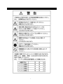
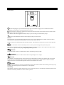
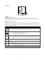
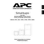
NEC 500 UPS
Uninterruptible Power Supply
100 VAC User’s Manual
990-5021, Revision 1, 12/98
N8580-31
Important!
Please read and save this manual. It provides installation and operating instructions that will help you get the fullest
performance and service life from your UPS.
About Your New UPS
This Uninterruptible Power Supply (UPS) is designed to prevent blackouts, brownouts, sags and surges from reaching your
computer and other valuable electronic equipment. This UPS also filters out small AC voltage fluctuations and isolates your
equipment from large disturbances by internally disconnecting from the AC voltage, while supplying power from its internal
batteries until the AC voltage returns to safe levels.
While running on battery, an internal alarm will sound (periodic beeps). The ON/TEST button may be pressed to silence the
UPS alarm for this or any other fault condition.
If the AC voltage does not return, the UPS will continue supplying power to the connected equipment until exhausted. A
sustained tone will sound three minutes before the UPS’s final low battery shutdown. The interface software provides automatic,
unattended shutdown.
i
Table of Contents
About Your New UPS ....................................................................................................................................................i
1. Safety.........................................................................................................................................................................1
2. Attention from the Safety Point of View .................................................................................................................2
3. Attention from the Operational and Maintenance Points of View .......................................................................3
4. Before Installing .......................................................................................................................................................3
5. Name and Function of Parts ...................................................................................................................................4
6. Installation ................................................................................................................................................................6
7. Operating Instructions.............................................................................................................................................7
8. Function ....................................................................................................................................................................8
9. Abnormal Conditions and Protection Functions ..................................................................................................9
10. Troubleshooting...................................................................................................................................................10
11. Maintenance and Checks ....................................................................................................................................11
Specifications.............................................................................................................................................................12
ii
1. Safety
1
2. Attention from the Safety Point of View
This section contains important instructions that should be followed during installation and maintenance of the NEC 500 and
batteries. It is intended for customers who setup, install, relocate, or maintain APC equipment.
Electrical Safety
•
EMC verification is VCCI - A.
•
Do not work alone under hazardous conditions.
•
High short circuit current through conductive materials could cause severe burns.
•
A licensed electrician is required to install permanently wired equipment.
•
Check that the power cord(s), plug(s), and sockets are in good condition.
•
To reduce the risk of electric shock when grounding cannot be verified, disconnect the equipment from the AC power outlet
before installing or connecting to other equipment. Reconnect the power cord only after all connections are made.
•
Do not handle any kind of metallic connector before the power has been removed.
•
Use one hand, whenever possible, to connect or disconnect signal cables to avoid a possible shock from touching two
surfaces with different electrical grounds.
•
Connect the equipment to a three wire AC outlet (two poles plus ground). The receptacle must be connected to appropriate
branch circuit/mains protection (fuse or circuit breaker). Connection to any other type of receptacle may result in a shock
hazard.
•
•
•
•
•
•
CAUTION! Deenergizing Safety
If the equipment has an internal energy source (the battery), the output may be energized when the unit is not connected to
an AC power outlet.
To deenergize pluggable equipment: first press the Off button for more than one second to switch the equipment off. Next
disconnect the equipment from the AC power outlet. Finally, disconnect the battery.
To deenergize permanently wired equipment: set the power switch to standby
. Next set the AC circuit breaker to
standby
. Then disconnect the batteries (including any expansion units). Finally, disconnect the AC power from the
building power supply.
Pluggable equipment includes a protective earth conductor which carries the leakage current from the load devices
(computer equipment). Total leakage current must not exceed 3.5 mA.
Use of this equipment in life support applications where failure of this equipment can reasonably be expected to cause the
failure of the life support equipment or to significantly effect its safety or effectiveness is not recommended.
WARNING! Battery Safety
This equipment contains potentially hazardous voltages. Do not attempt to disassemble the unit. The only exception is
for equipment containing batteries. Battery replacement using the procedures below is permissible. Except for the battery,
the unit contains no user serviceable parts. Repairs are performed only by factory trained service personnel.
Batteries must be recycled. Deliver the battery to an appropriate recycling facility or ship it to the supplier in the
new battery’s packing material. See the new battery instructions for more information.
•
•
•
Do not dispose of batteries in a fire. The batteries may explode.
Do not open or mutilate batteries. They contain an electrolyte which is toxic and harmful to the skin and eyes.
To avoid personal injury due to energy hazard, remove wrist watches and jewelry such as rings when replacing the batteries.
Use tools with insulated handles.
•
Replace batteries with the same number and type of batteries as originally installed in the equipment.
Handling Safety
⇒
⇒
•
•
•
•
<18 kg (<40 lb.)
⇒
32-55 kg (70-120 lb.)
18-32 kg (40-70 lb.)
⇒ >55 kg (>120 lb.)
Be careful. Do not lift heavy loads without assistance.
Equipment with casters is built to move on a smooth surface without any obstacles.
Do not use a ramp inclined at more than 10°.
This equipment is intended for installation in a temperature-controlled (0° - 40° C) indoor area, free of conductive
contaminants.
2
3. Attention from the Operational and Maintenance Points of View
Please charge the battery.
The battery may not be fully charged when your UPS arrives. Please allow four to six hours for charging.
To turn off the UPS, set the Enable switch to OFF.
Pressing the Off button, does not turn off the UPS. To manually turn it off, set the Enable switch to OFF.
When the UPS has been unused or in storage, charge the battery before use.
The battery’s charge will dissipate with disuse. Allow four to six hours to charge the battery before using.
Be careful in choice of circuit breaker.
Be careful of voltage sensitivity when setting up a circuit breaker on the input side of the UPS. If there is current leakage from
the loads, set the sensitivity higher.
Do not change the frequency of the UPS.
The frequency setting is either 50 Hz. or 60 Hz. It is preset and should not be changed.
Use reliable input power.
The AC line voltage to the UPS should be reliable, without large fluctuations.
Set up the environment for the UPS.
The UPS should be placed in an environment within its temperature and humidity specifications and avoiding direct sunlight.
Allow airflow around the UPS.
The airflow around the UPS should be adequate to provide cooling.
Replace the battery.
Replace the battery at the recommended intervals.
Do not operate the UPS with its cover removed.
Using the UPS without its cover is a safety and electrical hazard.
Exercise caution when changing or adding loads.
Although loads may be changed or added while the UPS is in operation, care should be taken not to overload the UPS or to
create an electrical hazard.
4. Before Installing
Inspection
Inspect the UPS upon receipt. Notify the carrier and dealer if there is damage. The packaging is recyclable; save it for reuse or
dispose of it properly.
Warning: Changes or modifications to this unit not expressly approved by the party responsible for compliance could void
the warranty.
Placement
Install the UPS in a protected area that is free of excessive dust and has adequate air flow. Do not operate the UPS where the
temperature and humidity is outside the specified limits.
3
5. Name and Function of Parts
1) Front View
5
0
0
With the UPS plugged in, press and release the large upper on/test button to supply power to the loads. The loads are
immediately powered while the UPS beeps and performs a self-test.
Press and release the small, lower off button to turn off power to the loads. It may be convenient to use the UPS as a master
on/off switch for the protected equipment.
Note: Whenever the UPS is plugged in and utility voltage is present, the charger maintains battery charge.
The on-line LED illuminates when the UPS is supplying utility power to the loads.
Self-test
The UPS performs a self-test automatically when turned on, and every two weeks thereafter (by default). Automatic self-test
eases maintenance requirements by eliminating the need for periodic manual self-tests.
During the self-test, the UPS briefly operates the loads on-battery. If the UPS passes the self-test, it returns to on-line operation.
If the UPS fails the self-test it immediately returns to on-line operation and lights the replace battery LED.
The loads are not affected by a failed test. Recharge the battery overnight and perform the self-test again. If the replace battery
LED is still on, replace the battery using the Replacing the Battery procedure.
SmartTrim
The SmartTrim LED comes on to indicate that the UPS is compensating for a high voltage.
SmartBoost
The SmartBoost LED comes on to indicate that the UPS is compensating for a low voltage.
Overload
When the UPS is overloaded (when the connected loads exceed the maximum specified in the “maximum load” section under
Specifications), the overload LED comes on and the UPS emits a sustained tone. The alarm remains on until the overload is
removed. Disconnect nonessential load equipment from the UPS to eliminate the overload.
On Battery
During on-battery operation, the on-battery LED illuminates and the UPS sounds an audible alarm consisting of four beeps every
30 seconds. The alarm stops when the UPS returns to on-line operation.
Low Battery
When the UPS is operating on-battery and the energy reserve of the battery runs low, the UPS beeps continuously until the UPS
shuts down from battery exhaustion or returns to on-line operation.
4
Replace Battery
If the battery fails a self-test, the UPS emits short beeps for one minute and the replace battery LED illuminates. The UPS repeats
the alarm every five hours. Perform the self-test procedure to confirm replace battery conditions. The alarm stops when the
battery passes the self-test.
100%
80%
60%
40%
20%
Battery Charge Bar Graph
The 5-LED display on the right of the front panel shows the present charge of the UPS’s battery as a percentage of the
battery’s capacity. When all five LEDs light, the battery is fully charged. The top LED goes out whenever the battery is
not 100% charged. When the lowest LED is flashing, the battery can supply less than two minutes of run time for the
load.
Shutdown Mode
In shutdown mode the UPS stops supplying power to the load, waiting for the return of utility power. If there is no utility power
present, external devices (e.g., servers) connected to the computer interface or the accessory slot can command the UPS to shut
down. This is normally done to preserve battery capacity after the graceful shutdown of protected servers. The UPS will scroll the
front panel indicators sequentially in shutdown mode.
85%
67%
50%
33%
17%
Load Bar Graph
The 5-LED display on the left of the front panel represents the power drawn from the UPS as a percentage of total
capacity. For example, if three LEDs are lit, the load is drawing between 50% and 67% of the UPS’s capacity. If all five
LEDs light, thoroughly test your complete system to make sure that the UPS will not become overloaded.
Cold Start
When the UPS is off and there is no utility power, use the cold start feature to apply power to the loads from the UPS’s battery.
Note: Cold start is not a normal condition.
•
Press and hold the on/test button until the UPS beeps.
• Release the on/test button during the beeps and the loads are powered within 4 seconds.
117
109
101
92
84
Utility Voltage Bar Graph
This UPS has a diagnostic feature that displays the utility voltage. With the UPS plugged into the normal utility power,
press and hold the on/test button to see the utility voltage bar graph display. After approximately four seconds the 5-LED
display on the right of the front panel shows the utility input voltage. Refer to the figure below for the voltage reading.
The display indicates that the voltage is between the displayed value from the list and the next higher value. For example,
with three LEDs lit, the input voltage is between 101 and 109 VAC.
If no LEDs come on and the UPS is plugged into a working AC power outlet, the line voltage is extremely low.
If all five LEDs come on, the line voltage is extremely high and should be checked by an electrician
Note: The UPS starts a self-test as part of this procedure. The self-test does not affect the voltage display.
The utility voltage bar graph has a margin of error of ± 4%.
5
2) Rear View
500 VA
Computer Interface Port
Power management software and interface kits can be used with this UPS. Use only kits supplied or approved by the
manufacturer. If used, connect the interface cable to the 9-pin computer interface port on the back panel of the UPS. Secure the
connector’s screws to complete the connection.
Ground Leads to TVSS Connector
The UPS features a convenient screw for connecting the ground lead on “transient voltage surge-suppression” (TVSS) devices
such as telephone and network line protectors. The TVSS connector provides grounding through the UPS’s power cord ground
conductor. To make a connection to the TVSS connector, loosen the screw and connect the surge suppression device’s ground
lead. Tighten the screw to secure the lead.
6. Installation
1.
Install the UPS
•
Plug the power cord into the UPS and into the AC voltage.
2.
Connect the Equipment
•
Do not power laser printers through the UPS.
•
Use your equipment’s power cords to connect to the UPS.
•
Turn on all connected equipment.
3.
Charge the battery
•
The UPS charges its battery whenever it is connected to utility power. The battery will charge fully
during the first 4 hours of normal operation. Do not expect full runtime during this initial charge
period.
4.
Connect the Computer Interface Port
5.
Connect the Ground Leads to the TVSS Connector (Optional)
6.
Power the Equipment
•
With the UPS plugged in, press and release the large upper on/test button to supply power to the
equipment plugged into the switched outlets.
Note: The UPS will not power up initially unless the AC voltage is in the normal operating range.
6
7. Operating Instructions
With the UPS plugged in, press and release the large upper on/test button to supply power to the loads.
Press and release the small, lower off button to turn off power to the loads.
Note: Whenever the UPS is plugged in and utility voltage is present, the charger maintains battery charge.
The on-line LED illuminates when the UPS is supplying utility power to the loads.
Self-test
The UPS performs a self-test automatically when turned on, and every two weeks thereafter (by default). During the self-test, the
UPS briefly operates the loads on-battery. If the UPS passes the self-test, it returns to on-line operation.
If the UPS fails the self-test it immediately returns to on-line operation and lights the replace battery LED.
SmartTrim
The SmartTrim LED comes on to indicate that the UPS is compensating for a high voltage.
SmartBoost
The SmartBoost LED comes on to indicate that the UPS is compensating for a low voltage.
Overload
When the UPS is overloaded (when the connected loads exceed the maximum specified in the “maximum load” section under
Specifications), the overload LED comes on and the UPS emits a sustained tone.
On Battery
During on-battery operation, the on-battery LED illuminates and the UPS sounds an audible alarm consisting of four beeps every
30 seconds.
Low Battery
When the UPS is operating on-battery and the energy reserve of the battery runs low, the UPS beeps continuously until the UPS
shuts down from battery exhaustion or returns to on-line operation.
100%
80%
60%
40%
Battery Charge Bar Graph
The 5-LED display on the right of the front panel shows the present charge of the UPS’s battery as a percentage of the
battery’s capacity.
20%
85%
67%
50%
33%
Load Bar Graph
The 5-LED display on the left of the front panel represents the power drawn from the UPS as a percentage of total
capacity.
17%
117
109
101
92
84
Utility Voltage Bar Graph
With the UPS plugged into the normal utility power, press and hold the on/test button to see the utility voltage bar graph
display. After approximately four seconds the 5-LED display on the right of the front panel shows the utility input
voltage.
The display indicates that the voltage is between the displayed value from the list and the next higher value.
Notes:
The UPS starts a self-test as part of this procedure. The self-test does not affect the voltage display.
The utility voltage bar graph has a margin of error of ± 4%.
Whenever the UPS is plugged in and utility voltage is present, the charger maintains battery charge.
7
8. Function
Self-test
The UPS performs a self-test automatically when turned on with the enable switch (by default). Automatic self-test eases
maintenance requirements by eliminating the need for periodic manual self-tests. During the self-test, the UPS briefly operates
the loads on-battery. If the UPS passes the self-test, it returns to on-line operation.
If the UPS fails the self-test it immediately returns to on-line operation and lights the replace battery LED. The loads are not
affected by a failed test. Recharge the battery overnight and perform the self-test again. If the replace battery LED is still on,
replace the battery using the Replacing the Battery procedure.
Automatic Voltage Regulation
A transformer with a winding that can be switched to boost or trim the AC line voltage is used to correct for low or high input
voltage without using the battery continuously.
Boost
AC Line to Boost
Boost to AC Line
92 V ±2%
96.5 V ±2%
AC Line to Trim
Trim to AC Line
108 V ±2%
104 V ±2%
Trim
8
9. Abnormal Conditions and Protection Functions
Smart Boost / Smart Trim
The SmartBoost LED comes on to indicate that the UPS is compensating for a low voltage.
The SmartTrim LED comes on to indicate that the UPS is compensating for a high voltage.
Overload
When the UPS is overloaded (when the connected loads exceed the maximum specified in the “maximum load” section under
Specifications), the overload LED comes on and the UPS emits a sustained tone. The alarm remains on until the overload is
removed. Disconnect nonessential load equipment from the UPS to eliminate the overload.
On Battery
During on-battery operation, the on-battery LED illuminates and the UPS sounds an audible alarm consisting of four beeps every
30 seconds. The alarm stops when the UPS returns to on-line operation.
Low Battery
When the UPS is operating on-battery and the energy reserve of the battery runs low, the UPS beeps continuously until the UPS
shuts down from battery exhaustion or returns to on-line operation.
Replace Battery
If the battery fails a self-test, the UPS emits short beeps for one minute and the replace battery LED illuminates. The UPS repeats
the alarm every five hours. Perform the self-test procedure to confirm replace battery conditions. The alarm stops when the
battery passes the self-test.
Battery Disconnected
The UPS checks for proper connection of batteries. If this check fails, the UPS emits an audible alarm, the replace battery LED
illuminates, and the battery charge bar graph turns off.
Service
If the UPS requires service do not return it to the dealer!
Follow these steps:
1. Use the Troubleshooting section to eliminate common problems.
2. Verify that no circuit breakers are tripped. A tripped circuit breaker is the most common UPS problem!
3. Note the model number of the UPS, the serial number, and the date purchased. A technician will ask you to describe
the problem and try to solve it
4. If the problem persists, call customer service.
5-7-1 Shiba, Minato Ward, Tokyo
Telnet: 8-23-29721
Fax: 8-23-29739
Internet:
E-mail:
•
9
10. Troubleshooting
Use the chart below to solve minor UPS installation problems. Contact NEC Technical Support Staff for assistance with
complex UPS problems.
Problem and Possible Cause
UPS will not turn on.
• On/test button not pushed.
• UPS not connected to AC voltage.
• UPS input circuit breaker tripped.
• Very low or no utility voltage.
• Battery not connected properly.
UPS will not turn off.
Internal UPS fault.
Solution
Set the UPS enable switch to 1. Set the Auto/Local switch to Local. Then
press the on/test button once to power the UPS and the loads.
Check that the power cable from the UPS to the power supply is securely
connected at both ends.
Reduce the load on the UPS by unplugging equipment and reset the circuit
breaker (on back of UPS) by pressing the plunger back in.
Check the AC power supply to the UPS with a table lamp. If very dim, have
the utility voltage checked.
Confirm the battery connections.
Do not attempt to use the UPS. Unplug the UPS and have it serviced
immediately.
UPS operates on-battery although normal line voltage exists.
Reduce the load on the UPS by unplugging equipment and reset the circuit
• UPS’s input circuit breaker tripped.
breaker(on back of UPS) by pressing the plunger back in.
Move the UPS to a different outlet on a different circuit.
• Very high, low, or distorted line voltage.
Test the input voltage with the utility voltage display. If acceptable to the load,
Inexpensive fuel powered generators can
reduce the UPS’s sensitivity. Consult the UPSC documentation for procedures.
distort the voltage.
UPS beeps occasionally.
Normal UPS operation.
None. The UPS is protecting the load.
UPS does not provide expected backup time.
Charge the battery. Batteries require recharging after extended outages. Also,
• The UPS’s battery is weak due to recent
they wear faster when put into service often or when operated at elevated
outage or is near the end of its service
temperatures. If the battery is near the end of its service life, consider
life.
replacing the battery even if the replace battery indicator is not yet lit.
Check the UPS’s load display. Unplug less needed equipment, such as printers.
• The UPS is overloaded.
All indicators are flashing and UPS emits a sustained tone .
Internal UPS fault.
Do not attempt to use the UPS. Turn the UPS off and have it serviced
immediately.
All indicators are off and UPS is plugged into wall outlet.
The UPS is shut down and the battery is
None. The UPS will return to normal operation when the power is restored
discharged from an extended outage.
and the battery has a sufficient charge.
The replace battery light is on.
Do another self test to see it clears.
• Weak batteries.
The replace battery light is flashing.
Confirm the battery connections. If the problem persists after recharging,
• Replacement batteries not connected
replace the batteries.
properly.
10
11. Maintenance and Checks
Storage
Storage Conditions
Store the UPS covered and upright in a cool, dry location, with its battery fully charged. Before storing, charge the UPS for at
least 4 hours.
Extended storage
• At -15 to +30 °C (+5 to +86 °F), charge the UPS’s battery every 6 months.
• At +30 to +45 °C (+86 to +113 °F), charge the UPS’s battery every 3 months.
Daily Check
Check the front bezel LEDs and the temperature of the room in which the UPS resides.
Scheduled Check
Once a year check the UPS for discoloration anywhere, frayed cables or power cords, or other signs of deterioration. Check that
the air flow around the UPS is adequate and that the vent is clear.
Battery Life
Temperature
Battery Life
Change Battery After
20 °C
5 years
4.5 years
30 °C
4 years
3.5 years
40 °C
2.5 years
2 years
11
Specifications
Acceptable input voltage
Output voltage
Input Protection
Frequency limits (on-line operation)
Transfer time
Maximum load
On-battery output voltage
On-battery frequency
On-battery waveshape
Protection
Noise Filter
Battery type
Typical battery life
Typical recharge time
Operating temperature
Storage temperature
Operating and storage relative humidity
Operating elevation
Storage elevation
Electromagnetic immunity
Audible noise in dBA at 1 m (3 ft)
Size (H x W x D)
Weight - net (shipping)
Safety approvals
EMC verification
N8580-31 500 VA
0 - 160 VAC
90 - 110 VAC
Resettable circuit breaker
50 or 60 Hz, +2%, -4%
2 ms (normal) 4 ms (maximum)
500 VA / 320 W
100 VAC
50 or 60, ± 0.1 Hz; unless synchronized to utility during brownout.
Low-distortion sine wave
Overcurrent and short-circuit protected, latching shutdown on overload.
Normal and common mode EMI/RFI suppression, 100 kHz to 10 MHz
Spill proof, maintenance free, sealed lead-acid
life varies; typical 2 years, depending on number of discharge cycles and ambient
temperature
2 to 5 hours from total discharge
0 to +40 ºC (+32 to +104 ºF)
-15 to +45 ºC (+5 to +113 ºF)
5 to 95%, non-condensing
0 to +3,000 m (0 to +10,000 ft)
0 to +15,000 m (0 to +50,000 ft)
IEC 801-2 level IV, 801-3 level III, 801-4 level IV
< 45
15.8 x 13.7 x 35.8 cm.
(6.2 x 5.4 x 14.1 in.)
11.6 (12.9) kg.
25.5 (28.5) lb.
Listed to UL 1778
VCCI Class 2
© NEC Corporation 1998
990-5021, Revision 1, 12/98
N8580-31
12