1
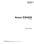
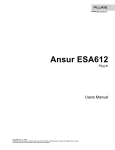
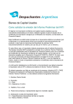
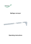
1
INSTALLER: THESE INSTRUCTIONS MUST BE CONVEYED TO AND REMAIN WITH THE HOMEOWNER.
Conforms to the standard ANSI Z21.91 2004 Ventless Firebox Enclosures for Unvented Room Heaters
INSTALLATION INSTRUCTIONS FOR THE
ZERO CLEARANCE VENTLESS FIREBOX ENCLOSURE
MODEL ZCVF36
MODEL ZCVF42
CERTIFIED FOR UNITED STATES USING ANSI METHODS
WARNING: If the information in these instructions is not followed exactly, a fire or
explosion may result causing property damage, personal injury or death.
FOR YOUR SAFETY
Do not store or use gasoline or other flammable vapours and liquids in the vicinity of
this or any other appliance.
WHAT TO DO IF YOU SMELL GAS:
• Do not try to light any appliance.
• Do not touch any electrical switch.
• Do not use any phone in your
building.
• Immediately call your gas supplier
from a neighbour’s phone. Follow the
gas supplier’s instructions.
• If you cannot reach your gas supplier,
call the fire department.
Installation and service must be performed by a qualified installer, service
agency or the gas supplier.
Wolf Steel Ltd., 24 Napoleon Rd., Barrie, ON L4M 4Y8 Canada . (705) 721-1212 .
fax(705)722-6031
W415-0527/ 09.29.05
2
TABLE of CONTENTS
PG 3
INTRODUCTION
Warranty
4-6
INSTALLATION & FINISHING
General Instructions
Hood Installation
Gas Connector Locations
Framing
Nailing Tab Instruction
Mantle Clearances
7
8 REPLACEMENTS
Replacements
Replacement Parts
Accessories
9 SERVICE HISTORY
OPTIONS
Optional Blower Installation
FOR USE ONLY WITH A ANSI Z21.11.2 LISTED
GAS-FIRED UNVENTED ROOM HEATER NOT
TO EXCEED
40,000 BTU/H
FOLLOW THE INSTRUCTIONS, AND
COMPLETE THE INSTALLATION OF THE
UNVENTED ROOM HEATER.
Carefully review the instructions supplied with
the unvented room heater for the mimimun
firebox size requirement.
DO NOT INSTALL AN APPLIANCE IN THIS
FIREBOX UNLESS THIS FIREBOX MEETS THE
MINIMUM DIMENSIONS REQUIRED FOR THE
INSTALLATION.
DO NOT BUILD A WOOD FIRE.
PLEASE RETAIN THIS MANUAL FOR FUTURE REFERENCE
WARNING
• Under no circumstances should this enclosure be modified.
• Provide adequate ventilation and combustion air. Refer to unvented room heaters installation instructions.
Never obstruct the front opening of the enclosure.
• Do not burn wood or other materials in this enclosure.
• Adults and especially children should be alerted to the hazards of high surface temperatures and should stay
away to avoid burns or clothing ignition. Keep young children and animals away when the ventless firebox
enclosure is hot.
• Due to high temperatures, the enclosure should be located out of traffic and away from furniture and
draperies.
• Clothing or other flammable material should not be placed on or near the enclosure.
• Any safety screen or guard removed for servicing must be replaced prior to operating the enclosure.
• It is imperative that the circulating air passageways in the enclosure are kept clean. The enclosure should
be inspected before use and at least annually by a qualified service person. More frequent cleaning may be
required due to excessive lint from carpeting, bedding material, etc. The enclosure area must be kept clear
and free from combustible materials, gasoline and other flammable vapours and liquids.
• Furniture or other objects must be kept a minimum of 4 feet away from the front of the ventless firebox
enclosure.
• Do not use this enclosure if any part has been under water. Immediately call a qualified service technician
to inspect the enclosure and to replace any part of the control system and any gas control which has been
under water.
• Do not allow fans to blow directly into the ventless firebox enclosure. Avoid any drafts that alter burner flame
patterns.
• Do not use a blower insert, heat exchanger insert or other accessory not approved for use with this
enclosure.
NOTE: CHANGES, OTHER THAN EDITORIAL, ARE DENOTED BY A VERTICAL LINE IN THE MARGIN
W415-0527 / 09.29.05
3
NAPOLEON gas fireplaces are manufactured under the strict Standard of the world recognized
ISO 9001:2000 Quality Assurance Certificate.
NAPOLEON products are designed with superior components and materials, assembled by trained craftsmen who take great
pride in their work. The burner and valve assembly are leak and test-fired at a quality test station. The complete ventless firebox
enclosure is test-fired and thoroughly inspected by a qualified technician before packaging to ensure that you, the customer,
receives the quality product that you expect from NAPOLEON.
NAPOLEON GAS FIREPLACE PRESIDENT’S LIFETIME LIMITED WARRANTY
The following materials and workmanship in your new NAPOLEON ventless firebox enclosure are warranted against defects for as long as you
own the ventless firebox enclosure. This covers: combustion chamber, heat exchanger, phazer™ logs and embers.
Electrical (110V and millivolt) components and wearable parts such as blowers, thermal switch, switches, wiring, and remote controls, are covered
and NAPOLEON will provide replacement parts free of charge during the first year of the limited warranty.
Labour related to warranty repair is covered free of charge during the first year. Repair work, however, requires the prior approval of an authorized company official. Labour costs to the account of NAPOLEON are based on a predetermined rate schedule and any repair work must be done
through an authorized NAPOLEON dealer.
CONDITIONS AND LIMITATIONS
NAPOLEON warrants its products against manufacturing defects to the original purchaser only -- i.e., the individual or legal entity (registered customer) whose name appears on the warranty registration card filed with NAPOLEON -- provided that the purchase was made
through an authorized NAPOLEON dealer and is subject to the following conditions and limitations:
This factory warranty is nontransferable and may not be extended whatsoever by any of our representatives.
The ventless firebox enclosure must be installed by a licenced, authorized service technician or contractor. Installation must be done in
accordance with the installation instructions included with the product and all local and national building and fire codes.
This limited warranty does not cover damages caused by misuse, lack of maintenance, accident, alterations, abuse or neglect and parts
installed from other manufacturers will nullify this warranty.
This limited warranty further does not cover any scratches, dents, corrosion or discolouring caused by excessive heat, abrasive and
chemical cleaners nor chipping on porcelain enamel parts, mechanical breakage of PHAZER™ logs and embers.
In the first year only, this warranty extends to the repair or replacement of warranted parts which are defective in material or workmanship
provided that the product has been operated in accordance with the operation instructions and under normal conditions.
After the first year, with respect to this President’s Limited Lifetime Warranty, NAPOLEON may, at its discretion, fully discharge all obligations
with respect to this warranty by refunding to the original warranted purchaser the wholesale price of any warranted but defective part(s).
After the first year, NAPOLEON will not be responsible for installation, labour or any other costs or expenses related to the reinstallation
of a warranted part, and such expenses are not covered by this warranty.
Notwithstanding any provisions contained in this President’s Limited Lifetime Warranty, NAPOLEON’S responsibility under this warranty
is defined as above and it shall not in any event extend to any incidental, consequential or indirect damages.
This warranty defines the obligations and liability of NAPOLEON with respect to the NAPOLEON ventless firebox enclosure and any
other warranties expressed or implied with respect to this product, its components or accessories are excluded.
NAPOLEON neither assumes, nor authorizes any third party to assume, on its behalf, any other liabilities with respect to the sale of
this product. NAPOLEON will not be responsible for: over-firing, inadequate ventilation, insufficient makeup air, or negative air pressures
which may or may not be caused by mechanical systems such as exhaust fans, furnaces, clothes dryers, etc.
Any damages to the ventless firebox enclosure, combustion chamber, brass trim or other component, due to water, weather damage,
long periods of dampness, condensation, damaging chemicals or cleaners will not be the responsibility of NAPOLEON.
The bill of sale or copy will be required together with a serial number and a model number when making any warranty claims from your
authorized dealer. The warranty registration card must be returned within fourteen days to register the warranty.
NAPOLEON reserves the right to have its representative inspect any product or part thereof prior to honouring any warranty claim.
ALL SPECIFICATIONS AND DESIGNS ARE SUBJECT TO CHANGE WITHOUT PRIOR NOTICE DUE TO ON-GOING PRODUCT IMPROVEMENTS. NAPOLEON® IS A REGISTERED
TRADEMARK OF WOLF STEEL LTD. PATENTS U.S. 5.303.693.801 - CAN. 2.073.411, 2.082.915. © WOLF STEEL LTD.
W415-0527/ 09.29.05
4
SPECIFICATIONS
GENERAL INSTRUCTIONS
THE INSTALLATION MUST CONFORM WITH LOCAL
CODES OR, IN THE ABSENCE OF LOCAL CODES WITH
THE NATIONAL FUEL GAS CODE, ANSI Z223.1 / NFPA
54 AND TO THE NATIONAL ELECTRICAL CODE, ANSI /
NFPA 70.
Use only accessories designed for and listed
with your specific firebox.
Not designed for use with a glass door.
Screen must be closed when appliance is in
operation.
ZCVF36
1 3/4”
42.000”
21 1/8”
HOOD INSTALLATION
Warning: Do not operate without hood in place.
31 7/8”
The firebox hood must not be modified or replaced with a
hood that may be provided with the unvented decorative
room heater.
32 1/2”
2
1
ZCVF42
1 3/4”
46 5/8”
FIGURE 1
Note: Remove the hood from the back side of the
carton by cutting the cable ties holding it in place.
1. Slide the edge of the hood into place on the top inside
surface of the ventless firebox enclosure to align with the
three pre-drilled holes.
2. Screw the hood securely into place with the three screws
provided. (FIGURE 1)
21 1/8”
36 3/8”
35 1/2”
W415-0527 / 09.29.05
5
GAS INLET LOCATIONS
There are five gas inlet locations on the ventless firebox enclosure. One on each side of the unit, two at the rear, and one
on the bottom. Using the following illustrations (FIGURE 2a-f) identify the preferred inlet and remove corresponding knock
out.
ZCVF36
7”
ZCVF42
7”
13 1/4”
13 1/4”
FIGURE 2a
FIGURE 2b
7”
7”
16 1/3”
13”
FIGURE 2c
FIGURE 2d
16 3/8”
16 3/8”
23 1/3”
21”
FIGURE 2e
FIGURE 2f
W415-0527/ 09.29.05
6
FRAMING
ANY CHANGE TO THIS ENCLOSURE CAN BE DANGEROUS AND IS PROHIBITED.
It is best to frame your ventless firebox enclosure after it is positioned. Use 2x4’s and frame to local building codes.
(FIGURE 3-5)
ZCVF36
ZCVF42
FIGURE 3
32 3/4"
35 3/4"
/4"
21 1
/4"
21 1
/2”
42 1
/8”
47 1
FIGURE 4
52 1/3”
55 5/8”
42 1/2”
47 1/8”
74 1/8”
78 5/8”
FIGURE 5
OUTSIDE
CHASE
21 1/4"
OUTSIDE
CHASE
42 1/2"
47 1/8"
INSIDE
CHASE
21 1/4”
42 1/2”
21 1/4"
6"
INSIDE
CHASE
21 1/4”
47 1/8”
6"
Minimum clearance to combustible construction from ventless firebox enclosure:
sides, back, bottom and top of the unit
0 inches
recessed depth
21 1/4 inches
Note: In order to avoid the possibility of exposed insulation or vapour barrier coming in contact with the ventless firebox
enclosure body, it is recommended that the walls of the ventless firebox enclosure enclosure be “finished” (ie: drywall/sheetrock), as you would finish any other outside wall of a home. This will ensure that clearance to combustibles is maintained
within the cavity.
When roughing in the ventless firebox enclosure, raise the ventless firebox enclosure to accommodate for the thickness of
the finished floor materials, i.e. tile, carpeting, hard wood.
Objects placed in front of the ventless firebox enclosure should be kept a minimum of 4 feet away from the front face.
W415-0527 / 09.29.05
7
NAILING TAB INSTRUCTION
1) Attach the nailing tabs to the corner posts using the 2
sheet metal screws supplied. Secure through the centre of
the top and bottom slots in the nailing tab and then through
the existing holes in the corner posts.
If there are no existing holes, follow these instructions:
Position the nailing tab so that the front face is offset with
the front edge of the corner post (approx. ½”). Centre the
nailing tab vertically on the corner post. (FIGURE 6a) Drill
through the centre of the top
and bottom slots in the nailing
tab. Secure using the two
sheet metal screws supplied.
This allows the nailing tab to
slide back and forth for desired
framing. (FIGURE 6b)
2) To determine the final
location of the nailing tab you
must first determine the width
of your finishing material (i.e.
drywall). This will determine
the dimension from the front
edge of the corner post to the
nailing tab. Once the nailing tab
is in the desired location, drill
through the centre hole of the
nailing tab. Secure with a sheet
metal screw*. (FIGURE 6c)
* Additional set screws may be installed.
MANTEL CLEARANCES
CORNER
POST
NAILING
TAB
TOP
SLOT
FIGURE 6a
Combustible materials may be installed flush with the front
of the ventless firebox enclosure but must not cover any
of the black face-areas of the ventless firebox enclosure.
Non-combustible material (brick, stone or ceramic tile) may
protrude in these areas.
Combustible mantel clearance can vary according to the
mantel depth. Use the graph to help evaluate the clearance
FIGURE 6b
FINISHING MATERIAL
FIGURE 7
MANTEL
7"MANTLE
MANTEL
6"MANTLE
7"
COMBUSTIBLE
MATERIALS
MANTEL
4"MANTLE
6"
STUD
4"
TOP OF UNIT
FIGURE 8
M
M
AA
N
N
T
T
L
E
E
L
H
E
I
G
H
T
7
6
5
4
CENTRE HOLE
4 567
MANTEL WIDTH
MANTLE
FIGURE 6c
W415-0527/ 09.29.05
8
OPTIONAL BLOWER INSTALLATION
INSTALLATION TO BE DONE BY A QUALIFIED INSTALLER
and must be electrically connected and grounded in
accordance with local codes. In the absence of local codes,
use the current ANSI/NFPA 70 National Electrical Code.
If the firebox was not previously equipped with a blower:
route a grounded 2-wire, 60hz power cable through the
junction plate cover. At this point it must be strain relieved
and insulated.
The three slots on the blower mounting bracket allow ease
of adjustment when attaching the blower. (FIGURE 10) For
a quiet running blower, do not allow the assembly to sit on
the firebox base.
Slide the vibration reducing pad (a) into the clip (c) and up
against the threaded stud (b) at the other end. The blower
must be able to be positioned entirely onto the pad.
Tilt the blower onto its side. Slide it past the controls and
into the clip (c).
B
FIGURE 10
The wire harness provided in this kit is a universal
harness. When installed, ensure that any excess wire is
contained, preventing it from making contact with moving
or hot objects. Because the blower is thermally activated,
when turned on, it will automatically start approximately
30 minutes after lighting the vent free room heater and will
run for approximately 30-45 after the vent free room heater
has been turned off. Use of the fan increases the output of
heat.
Drywall dust will penetrate into the blower bearings
causing irreparable damage. Care must be taken to
prevent drywall dust from coming into contact with the
blower or its compartment. Any damage resulting from this
condition is not covered by the warranty policy.
A
C
W415-0527 / 09.29.05
Secure to the threaded stud using the lock washer and
wing nut provided. Ensure that the blower does not touch
the firebox base or the firebox. (FIGURE 9) Attach the
connectors from the black and red wires to the blower.
9
Note: In either application it is necessary to remove the variable speed switch from the wiring harness and
install into an electrical switch box as per electrical codes.
WITH THERMAL SWITCH BRACKET
WITHOUT THERMAL SWITCH BRACKET
1. Remove the hearth pads and the blower access cover.
(FIGURE 9)
2. Install the blower using the optional blower installation
instructions.
3. Pull the black and white thermal disc wires through the
7/8” bushing in the blower access cover.
4. Cut the white wire as close to the connector as
possible. (FIGURE 11).
5. Cut the red wire as close to the plug as possible.
(FIGURE 11)
6. Using a box connector, connect supply wire through
the junction cover plate located on the right sidce of
the firebox enclosure.
7. Connect the red and white wires to the power supply.
Attach the ground to the ground screw on the junction
plate cover.
8. Replace the blower access cover.
9. Attach the black & white wires to the back of the
thermal switch and install at the rear of the firebox
using the thermal switch support bracket as circled in
(FIGURE 9).
10. Replace the hearth pads.
1. Remove the hearth pads and blower access cover.
(FIGURE 9)
2. Install the blower using the optional blower installation
instructions.
3. Cut the red wire as close to the plug as possible.
4. Cut the black wire as close to the flag connection as
possible. (FIGURE 12).
5. Using a box connector, connect supply wire though
the junction cover plate located on the right side of the
firebox enclosure.
6. Attach the ground to the ground screw on the junction
plate cover.
7. Replace the blower access cover plate and hearth
pads.
BLOWER
BLACK
RED
BLOWER
WHITE
THERMAL DISC
BLACK
RED
VARIABLE
SPEED
SWITCH
WHITE
FIGURE 12
THERMAL DISC
1
3
4
1. Hearth Pads
2. Blower Access Cover
3. Thermal Switch Support Bracket
4. 7/8” Bushing
5. Junction Box
5
EW
2
CR
FIGURE 11
VARIABLE
SPEED
SWITCH
GR O U N D
S
FIGURE 9
W415-0527/ 09.29.05
10
REPLACEMENTS
Contact your dealer for questions concerning prices and
availability of replacement parts. Normally all parts can be
ordered through your Napoleon dealer or distributor.
When ordering replacement parts always give the following
information:
1. Model & Serial Number of ventless firebox enclosure
2. Installation date of ventless firebox enclosure
FOR WARRANTY REPLACEMENT PARTS, A
PHOTOCOPY OF THE ORIGINAL INVOICE WILL BE
REQUIRED TO HONOUR THE CLAIM.
3. Part Number
4. Description of part
5. Finish
#
1*
2
3
4
5*
6
7
ZCVF36
ZCVF42
REPLACEMENT PARTS
REPLACEMENT PARTS
PART No.
W385-0245
W565-0084
W555-0056
W335-0044
W500-0192
W475-0400
W475-0386
DESCRIPTION
Napoleon Logo
Curtain Mesh
Curtain Rod
Hood
Panel Brackets
Hearth Pad (Right)
Hearth Pad (Left)
#
1*
2
3
4
5*
6
7
PART No.
W385-0245
W565-0085
W555-0057
W335-0045
W500-0192
W475-0399
W475-0382
ACCESSORIES
ACCESSORIES
#
8*
9*
10*
11
12
13*
14
15*
PART No.
111KT
112KT
GD810-KT
DKZC36SS
TBZC36K
TBZC36SS
GZ550-1KT
W500-0033
DESCRIPTION
Napoleon Logo
Curtain Mesh
Curtain Rod
Hood
Panel Brackets
Hearth Pad (Right)
Hearth Pad (Left)
#
8*
9*
10*
11
12
13*
14
15*
DESCRIPTION
Outside Air Kit
Adaptor Plate, Outside Air Kit
Brick Panels (Cobblestone)
Decorative Door
36” 3” Bevelled trim (textured black)
36” 3” Bevelled trim (satin chrome)
Blower kit
Switch Wall Mounting Plate
PART No.
111KT
112KT
GD809-KT
DKZC42SS
TBZC42K
TBZC42SS
GZ550-1KT
W500-0033
DESCRIPTION
111-KT Kit
112 Collars
Brick Panels (Cobblestone)
Decorative Door
42” 3” Bevelled trim (textured black)
42” 3” Bevelled trim (satin chrome)
Blower kit
Switch Wall Mounting Plate
* IDENTIFIES ITEMS WHICH ARE NOT ILLUSTRATED. FOR FURTHER INFORMATION, CONTACT YOUR NAPOLEON DEALER.
12
11
3
2
14
7
4
6
W415-0527 / 09.29.05
Date
Dealer Name
Service Technician
Name
Service Performed
This fireplace must be serviced annually depending on usage.
Wolf Steel Fireplace Service History
Special Concerns
11
W415-0527/ 09.29.05
12
NOTES
W415-0527 / 09.29.05