1
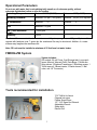
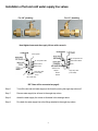
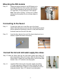
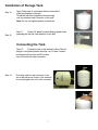
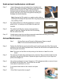
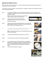
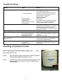
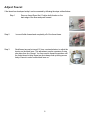
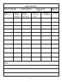
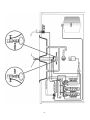
INSTALLATION, OPERATION AND MAINTENANCE MANUAL
Warning
Please read carefully before proceeding with installation. Your failure to follow a attached
instructions or operating parameters may lead to the product's failure and possible
damage to property.
*******************************************************************************************
Save manual for future reference.
Model FMRO4-ZW
ZER O WASTE R EVER SE OSMOSIS SYSTEM
Thank you for your purchase of a Flowmatic Reverse Osmosis system. With proper installation and
maintenance, this system will provide you with high quality water for years to come. All of Flowmatic water
enhancement products are rigorously tested by independent laboratories for safety and reliability. If you
have any questions or concerns, please contact our customer service department at 1-800-461-4406
TABLE OF CONTENTS
Operational Parameters ............................................................ 3
ZRO-4 System .......................................................................... 3
Tools recommended for Installation ........................................... 3
Installation of faucet .................................................................. 4
Installation of hot and cold water line fittings ................................ 5
Mounting the RO module .......................................................... 6
Connecting the tube to faucet .................................................... 6
Connecting the tubes to the hot & cold water supply valves.
6
Installation of storage tank ......................................................... 7
Connecting the tank .................................................................. 7
Start up instructions .................................................................. 8
Semi-annual Maintenance ......................................................... 8
Annual Maintenance ................................................................. 9
Membrane Maintenance ........................................................... 10
Trouble Shooting ...................................................................... 11
Check air pressure in the tank .................................................... 11
Adjust faucet ............................................................................. 12
Service Record ......................................................................... 13
Warranty .................................................................................. 14
Drawing and Parts list ................................................................ 15
Other products .......................................................................... 16
2
Operational Parameters
Do not use with water that is microbiologically unsafe or of unknown quality, without
adequate disinfection before or after the system.
Operating Temperatures:
Maximum 100°F (37.8°C)
Minimum 40°F ( 4.4°C)
Operating Pressure:
Maximum 100 psi (7.43 g/cm2) Minimum
pH Parameters:
Maximum
Iron:
Maximum 0.2 ppm
TDS (Total Dissolved
Solids):
Turbidity:
< 1000 ppm
11
Minimum
40 psi (2.80 kg/cm2)
3
<5NTU
Hardness: Recommended hardness not to exceed 7 grains per gallon, or 120ppm. System will
operate with hardness over 7 grains but the membrane life may be shortened. Addition of a water
softener may lengthen the membrane life.
Note: RO unit must be installed a mimimun of 25 feet from hot water heater.
FMRO4-ZW System
System includes:
RO module, 24 volt Pump, 3 gal Storage tank, Long reach
faucet, Manual, Warranty Card, Parts Bags, (2 Water line
fitting valves, 2 Washers,Transformer, 2 Mounting screws, 1
Teflon tape roll, 2 Brass inserts, 2 Plastic sleeves, 1 Ball
v
al
v
e,one1/
4”Connec
t
or
)
Tools recommended for installation
7/
16”Drill bit for faucet
Channel lock piers
Phillips Screw Driver
1/2" - 5/8" Open End Wrench
Adjustable Wrench
Sharp knife
Electric Drill
3
Installation of Faucet
Caution: Porcelain sink surface material is extremely hard and may crack or chip. Use extreme
caution when drilling. Watts accepts no responsibility for damage resulting from the installation of
the faucet.
Black Locating Washer
(used where a 1/2" hole is
available, reverse when
mounting on stainless steel
or when using drilled hole)
Brass Insert (sleeve)
1 /4" Tub
Plastic Sleeve
1 /4" Compression Nut
Step 1
Step 2
D etermine desired location to drill a hole for the faucet on your sink.
Usi
ngav
ar
i
abl
espeeddr
i
l
lont
hesl
owestspeed,dr
i
l
la7/
16”hol
ef
ort
hefaucet.Use
water to keep the drill bit cool while drilling. (If the drill bit gets hot it may cause the
porcelain to crack or chip).
Step 3
Place the escutcheon chrome plate and the black rubber washer on the
faucet shank. (Parts found in faucet parts bag).
Step 4
Insert the faucet shank through the hole in sink and let it rest on the sink top.
Step 5
From the underside of the sink slide on the locating washer, lock washer and brass nut
onto the shank. Check orientation of faucet then tighten brass nut securely.
4
Installation of hot and cold water supply line valves
For3/
8”pl
umbi
ng
For1/
2”pl
umbi
ng
Hand tighten brass nuts then apply 1/4 turn with a wrench.
To RO System
1/4" Compression Nut
1/4" Compression Nut
Plastic Sleeve Brass
Plastic Sleeve
Insert
Brass Insert
3/8"M X 1/2"F
Adapter
Angle Stop Valve
(not included)
Rubber
1/2"M X 3/8"F X 1/4"Comp.
with needle valve
Angle Stop Valve
(not included)
Washer
RO Tubes will be connected on page 6.
Step 6
Turn off the hot and cold water supply to the faucet by turning the angle stop valves off.
Step 7
Remove water supply line at faucet to the angle stop valves.
Step 8
Attach the water supply line valves as illustrated in the drawings above.
Step 9
Re -attach the water supply line to the fittings attached to the angle stop valves.
5
Mounting the RO module
Step 10
Determine the best location for the RO Module to be
mounted and allow for future system maintenance.
Use a Phillips screwdriver and secure the screws 5
3/
4”apar
tand16”f
r
om t
hebot
t
om oft
hec
abi
net
.
Note: There will be (2) Blue, (1) Green and (1) Black
coming from the module. Do not cut these tubes at
this time.
Connecting to the faucet
Step 11
Connect blue tube from in-line filter over to the faucet
shank. Place the brass nut onto the tube, followed by the plastic
sleeve (tapered end pointing to the end of tube) and then place
the brass insert into the end of the tube.
Step 12
Insert the blue tube into the end of the faucet shank and use a
wrench to tighten the brass nut securely.
Connect the hot and cold water supply line valves
St
ep13I
ns
er
tt
heGr
eent
ubei
nt
ot
heCol
dwat
erneedl
ev
al
v
ef
i
t
t
i
ng1/
4”
tube compression fitting until it stops. Slide the Nut and Plastic
Sleeve down to where you can thread them onto the male pipe
t
hr
eads
.Us
ea1/
2”wr
enc
ht
os
ec
ur
el
yt
i
ght
en.
Step 14
Insert the Black tube into the Hot water needle valve fitting
1/
4”t
ubec
ompr
es
s
i
onf
i
t
t
i
ngunt
i
l
i
ts
t
ops
.Sl
i
det
heNutand
the Plastic Sleeve down to where you can thread them onto the
mal
epi
pet
hr
eads
.Us
ea1/
2”wr
enc
ht
os
ec
ur
el
yt
i
ght
en.
6
Installation of Storage Tank
Step 15
Step 16
Apply Teflon tape in a clockwise direction around the
male pipe threads on the tank.
Thread the ball valve (supplied in the parts bag)
onto the stainless steel connector on the tank.
Note: Do not over tighten plastics connections.
Step 17
Thr
ead1/
4”pl
as
t
i
cc
onnec
t
orf
i
t
t
i
ng(
s
uppl
i
edi
nt
he
parts bag) into the ball valve attached to the tank.
Connecting the Tank
Step 18
Postion the tank in the desired location. Stand it
upr
i
ghtorus
i
ngbl
ac
kpl
as
t
i
cs
t
andl
ayi
toni
t
’
ss
i
de. Connect
remaining blue tube from he RO module
over to the tank ball valve connector.
Step 19
Push blue tube into the connector on the
end of ball valve until it stops. Use a wrench
to securely tighten the nut on the connector.
7
Start up Instructions
Warning: To prevent the possibility of electrical shock, clean up any water on
cabinet floor and dry all water from outside of RO unit.
Step 1
Turn on the incoming hot and cold water angle stop valves. Turn
on the water line needle valves by turning counter clockwise.
Check the system for leaks and tighten fittings as necessary.
Note: Check daily over the next week to ensure no leaks are
present.
Step 2
Plug the (24 volt) transformer power cord
connector into the RO system wire harness connector (labeled
transformer.)
Step 3
Plug the transformer into the electrical outlet under the sink.
Step 4
Ensure ball valve on tank is open.
Step 5
Open the RO faucet and leave it open until water begins to drip. Then close the faucet. The
tank will take 2 to 4 hours to fill completely.
Note: Water may be cloudy or milky due to air in the system. This conditions will
resolve its self after a couple of tanks of water. After a final filter change you will see
gray water until the carbon particles have flushed from the filter.
Step 6
After the tank has filled once, open the RO faucet and drain the tank.
Step 7
Close RO faucet and allow the tank to fill, (2-4 hours). System is now ready to use.
Note: This system can be hooked up to an ice maker. Place a tee after the final filter and before the
faucet. It is recommended to install a ball valve on the ice maker line. This enables you to shut off the
water supply to ice maker while the tank is filled and flushed to remove the carbon particles from the final
filter. Each time the tank becomes empty you will need to close the water supply to the ice maker until
the tank refills.
Semi-annual maintenance
Step 1
Turn off the water supply line needle valves.
Step 2
Close the ball valve on the tank.
Step 3
Step 4
Step 5
Step 6
Open the RO faucet to allow the system to depressurize for 5 - 10 minutes before
attempting to remove Housings.
Unplug transformer from electrical outlet.
Carefully remove the filter housings and pour water out of the housings. Dispose of
the used filters.
Wash housings with mild soap and rinse thoroughly with water.
8
Semi-annual maintenance continued
Step 7
Inspect O-rings for wear and replace them if needed (order
part no. WP113029 from Watts.) Lubricate O-rings with a water
soluble lubricant such as KY Jelly®, (petroleum based
lubricants such as Vaseline® must not be used.) Be sure to
properly seat the O-ring in the housing before threading the
housings onto the lid assembly.
Note: Keeping the RO module in an upright position while reattaching the housings will help ensure the o-ring stays properly seated and reduces
the possiblity of leaks.
Step 8
The sediment filter has a cloth like appearance. It must be
placed in the 1 st housing on the left where the water inlet
connects.
Step 9
The carbon bock filter has a mesh covering and has a
gasket on each end. Replace the filter in the 2nd housing
with the carbon block filter.
Step 10
Visually inspect oring to be sure they are properly seated before threading the housing
onto the lid assembly and hand tighten securely.
Annual Maintenance
Step 1.
Step 2
Perform Semi-annual Preventive Maintenance Steps on page 8.
Note: For the annual maintenance drain the tank.
Replace the final filter by removing the white nuts from both ends of the filter. Remove the
connectors from both ends (keep and reuse). Discard the old final filter and replace with new
filter reusing the connectors.
Note: Flow arrow on final filter must be pointing in the direction of water flow to the
faucet.
Step 3
The tank shut off switch has quick-disconnect connectors. Remove the blue tube from the
tank side of the tank shut-off switch. Depress the gray ring with the tip of your finger and
pull the tube straight out .
Step 4
Use a clean eye dropper to insert ½ teaspoon of 3% hydrogen peroxide or common house
hold bleach into the blue tube. (This will flow into the tank
once water is turned back on to unit.)
Step 5
To reconnect insert tube into the connector and push
firmly.
Step 6
Follow Start Up procedure on page 8.
9
Membrane Maintenance
Membrane filters have a life expectancy of 2 to 5 years, depending on the incoming water conditions and
the amount of use of the RO system.
If at any time you notice a reduction in water production or a change in the taste of the RO water, it could be
time to replace the membrane.
Step 1
To change the membrane, use a 5/8" wrench to remove the nut from the cap side of the
membrane housing (the end with only one elbow). Remove the cap from the white horizontal
membrane housing.
Note: To assist with the removal of cap a double sided
wrench canbe purchased from Watts Premier.
Step 2
Using a pair of pliers, grip and pull firmly on the
membrane filter to remove it from the housing and
discard the membrane.
Step 3
Unwrap new membrane filter and lubricate the o-rings with water
soluble lubrication such as KY Jelly® . Insert the end with the two
black O-rings into the membrane housing.
Step 4
Once membrane filter has been inserted into the housing you must take your thumbs and give a firm
push to properly seat the membrane. Replace membrane housing cap and tighten.
Note: To be properly seated the tip of the membrane filter must be
below the housing edge.
Step 5
Screw the membrane filter housing cap back on securely.
Step 6
Connect the green tube back to the membrane cap fitting.
Step 7
You must change the flow restrictor each time you change the
Membrane filter. Replace the existing flow restrictor with the new
one by removing the White compression nuts. Make sure the
arrow is pointing toward the check valves and hot water line
fitting.
Step 8
Follow Start Up procedures on page 8.
Trouble shooting
Problem
Cause
Solution
Low/slow production
Excessive air pressure in tank
Relieve pressure at Schrader valve on tank (set
to 7 psi with the tank empty)
Pump not operating
Fouled membrane
Plugged pre-filters
Crimped tubing
Angle stop or water line valve
not fully opened
Milky colored water
Air in the system
Faucet Dripping
Pump short cycles
Needs adjustment
Ball valve on tank closed
Blue tube blocked between
the tank and RO system
Faulty pressure switch
Damaged/Dry O-ring
Bowl leaks at the top after
changing the filters
Pump constantly running
Electrical fault
Faucet left on
Plugged pre-filters
Wiring connection broken (plug 110 AC wall
plug back in at wall and/or reconnect the 24
VAC wire harness connectors)
Replace pump if needed
Replace membrane
Replace filters
Check tubes to make sure they are not kinked
Ensure valves are opened by turning valve
handle counter clockwise until it stops
Air in the system is a normal occurrence with
initial start up of the RO system. This milky look
will disappear during normal use within 1-2
weeks. If condition reoccurs after filter changes,
drain tank 1 to 2 times.
see page 12
Open the ball valve on the top of the tank
Remove kinked/damaged section and replace if
necessary
Call for technical support
Lubricate with water soluble lubricant or replace
O-ring as necessary (Do not use Vaseline or
other petroleum based lubricants)
Call for technical support
Close faucet and let tank fill for 2 to 3 hours
Replace filters
Checking air pressure in tank
Note: Check air pressure when tank is empty. Step 1
Open
faucet and drain the tank.
Step 2
Using a digital air gauge check the air pressure in the tank.
There should always be between 5-7 psi.
Step 3
If you have more than 7 psi release air and recheck. If you
have less than 5 psi, add air. Air can be added with a
bicycle pump.
11
Adjust Faucet
If the faucet has developed a drip it can be corrected by following the steps outlined below.
Step 1
Remove faucet Spout first. Position both thumbs on the
back edge of the lever and push forward.
Step 2
Lever will slide forward and completely off of the faucet base.
Step 3
Small brass tee can be turned 1/2 turn, counterclockwise, to adjust the
tension on the black lever. This adjustment may be necessary to stop
slow drips from tip of faucet. You may need to repeat the process until
the faucet does not drip. Brass tee must always end up facing across
body of faucet in order to slide black lever on.
12
SERVICE RECORD
DATE OF PURCHASE
/
/
DATE OF INSTALL
/
/
Date of
Maintenance
(6 mos.)
2nd stage
Carbon Block
(6 mos.)
1st stage
Sediment
INSTALLED BY
NAME:
(1 yr.)
Final Filter
Carbon
NOTES:
13
(2-5 yrs.)
TFM Memb.
SERIAL NO.
#
OTHER
Limited Warranty
What your Warranty Covers:
Limited 3 year warrranty on the Reverse Osmosis module, tank and faucet if defective.
1 year warranty on the electrical components, pump, pressure switch, solenoid valve, and transformer if defective.
No warranty on replaceable filters and membranes.
Return unit after obtaining a return authorization (see below), less tank, within 3 year of original retail purchase,
FLOWMATIC SYSTEMS will repair or, at FLOWMATIC‘
S option, replace the system at no charge.
How to obtain Warranty Service:
For warranty service, call 1-800-461-4406 for a return authorization number. Then, ship your Reverse Osmosis unit (less
tank) to our factory, freight and insurance prepaid, with proof of date of original purchase. Please include a note stating the
problem. Flowmatic will repair it, or replace it, and ship it back to you prepaid.
What this warranty does not cover:
This warranty does not cover defects resulting from improper installation, (contrary to FLOWMATIC SYSTEM's printed
instructions), from abuse, misuse, misapplication, improper maintenance, neglect, alteration, accidents, casualties, fire, flood,
freezing, environmental factors, or other such acts of God.
This warranty will be void if defects occur due to failure to observe the following conditions:
1.
The Reverse Osmosis System must be hooked up to a potable municipal or well cold water supply.
2.
The hardness of the water should not exceed 7 grains per gallon, or 120 ppm.
3.
Maximum incoming iron must be less than 0.2 ppm.
4.
The pH of the water must not be lower than 3 or higher than 11.
5.
The incoming water pressure must be between 40 and 100 pounds per square inch.
6.
Incoming water to the RO cannot exceed 105 degrees F (40 degrees C.)
7.
Incoming TDS/Total Dissolved Solids not to exceed 1800 ppm.
8.
Do not use with water that is micro-biologically unsafe or of unknown quality without
adequate disinfection before or after the system.
This warranty does not cover any equipment that is relocated from the site of its original installation.
This warranty does not cover any equipment that is installed or used outside the United States of America and Canada.
LIMITATIONS AND EXCLUSIONS:
FLOWMATIC SYSTEMS WILL NOT BE RESPONSIBLE FOR ANY IMPLIED WARRANTIES, INCLUDING THOSE
OF MERCHANTIBILITY AND FITNESS FOR A PARTICULAR PURPOSE. FLOWMATIC WILL NOT BE
RESPONSIBLE FOR ANY INCIDENTAL OR CONSEQUENTIAL DAMAGES, INCLUDING TRAVEL EXPENSE,
TELEPHONE CHARGES, LOSS OF REVENUE, LOSS OF TIME, INCONVENIENCE, LOSS OF USE OF THE
EQUIPMENT, AND DAMAGE CAUSED BY THIS EQUIPMENT AND ITS FAILURE TO FUNCTION PROPERLY.
THIS WARRANTY SETS FORTH ALL OF FLOWMATIC'S RESPONSIBILITIES REGARDING THIS EQUIPMENT.
OTHER CONDITIONS:
If Flowmatic chooses to replace the equipment, Flowmatic Systems may replace it with reconditioned equipment. Parts used in
repairing or replacing the equipment will be warranted for 90 days from the date the equipment is returned to you or for the
remainder of the original warranty period, whichever is longer. This warranty is not assignable or transferable.
YOUR RIGHTS UNDER STATE LAW:
Some states do not allow limitations on how long an implied warranty lasts, and some states do not allow the exclusion or
limitation of incidental or consequential damages, so the above limitations or exclusions may not apply. This warranty gives
you specific legal rights, and you may have other legal rights which vary from state to state.
15
21