1
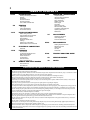
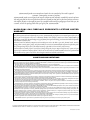
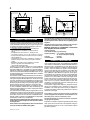
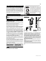
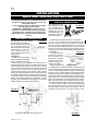
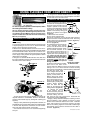
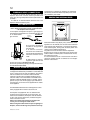
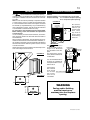
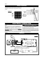
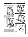
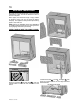
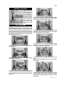
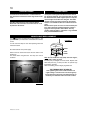
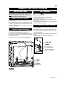
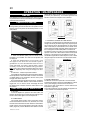
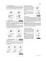
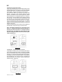
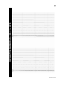
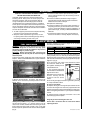
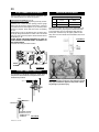
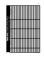
1
INSTALLER: THESE INSTRUCTIONS MUST BE CONVEYED TO AND REMAIN WITH THE HOMEOWNER.
INSTALLATION AND
OPERATION INSTRUCTIONS
CERTIFIED UNDER CANADIAN AND AMERICAN NATIONAL STANDARDS: CSA 2.22, ANSI Z21.50 FOR VENTED GAS FIREPLACES.
BGD90NT
NATURAL GAS
BGD90PT
PROPANE
CERTIFIED FOR CANADA AND UNITED STATES USING ANSI/CSA METHODS.
SAFETY INFORMATION
WARNING: If the information in these
instructions are not followed exactly, a fire
or explosion may result causing property
damage, personal injury or loss of life.
- Do not store or use gasoline or other
flammable vapors and liquids in the vicinity
of this or any other appliance.
- WHAT TO DO IF YOU SMELL GAS:
Do not try to light any appliance.
Do not touch any electrical switch; do
not use any phone in your building.
Immediately call your gas supplier from
a neighbour’s phone. Follow the gas
supplier’s instructions.
If you cannot reach your gas supplier,
call the fire department.
- Installation and service must be
performed by a qualified installer, service
agency or the supplier.
Wolf Steel Ltd., 24 Napoleon Rd., Barrie, ON L4M 4Y8 Canada • (705)721-1212 • fax(705)722-6031
W415-0614 / A / 07.24.07
www.napoleonfireplaces.com • [email protected]
$10.00
W415-0614 / A / 07.24.07
2
TABLE of CONTENTS
PG2-5
20-24
INTRODUCTION
Warnings and Safety Precautions
Warranty
Dimensions
General Instructions
General Information
Care of Glass & Plated Parts
5-9
Fireplace Operation
Hand Held Remote Operation
Temperature Display
Room Thermostat
SMART Thermostat
Flame Height
Fan Shield
Child Proof Function
Remote Auxiliary Outlet
Low Battery / Manual Bypass
Operating Instructions
Maintenance
VENTING
Vent lengths
Venting Specifications
Air Terminal Locations
10-14
INSTALLATION/FRAMING
Wall & Ceiling Protection
Using Flexible Vent Components
Fireplace Vent Connection
Gas Installation
Restricting Vertical Vents
Framing
Clearance to Combustibles
Mantle Clearances and Enclosures
14
24
25-26
REPLACEMENTS
Ordering Replacement Parts
Replacement Parts
Terminal Kits
Vent Kits
Accessories
ELECTRICAL CONNECTION
FINISHING
Door Removal
Log Shipping Bracket Removal
Brick Panel Installation
Andiron Placement
Log Placement
Charcoal Embers
Night Light Replacement
19
ADJUSTMENTS
Pilot Burner Adjustment
Venturi Adjustment
Air Control Rod Access
Schematic
15-18
OPERATION / MAINTENANCE
27-28
TROUBLE SHOOTING GUIDE
29
SERVICE HISTORY
30
NOTES
REMOTE AND VALVE ACCESS
Remote Removal
Valve Removal
PLEASE RETAIN THIS MANUAL FOR FUTURE REFERENCE
WARNING
• Do not burn wood or other materials in this fireplace.
• Adults and especially children should be alerted to the hazards of high surface temperatures and should stay away to avoid burns or clothing ignition. Supervise young children when they are in the same room as the fireplace.
• Ensure you have incorporated adequate safety measure to protect infants/toddlers from touching hot surfaces.
• Due to high temperatures, the fireplace should be located out of traffic and away from furniture and draperies.
• Clothing or other flammable material should not be placed on or near the fireplace.
• Check with your local hearth specialty dealer for safety screens and hearth guards to protect children from hot surfaces. These screens
and guards must be fastened to the floor.
• Any safety screen or guard removed for servicing must be replaced prior to operating the fireplace.
• Even after the fireplace is out, the glass and/or screen will remain hot for an extended period of time.
• It is imperative that the control compartments, burners and circulating blower and its passageway in the fireplace and venting system are
kept clean. The fireplace and its venting system should be inspected before use and at least annually by a qualified service person. More
frequent cleaning may be required due to excessive lint from carpeting, bedding material, etc. The fireplace area must be kept clear and
free from combustible materials, gasoline and other flammable vapours and liquids.
• Under no circumstances should this fireplace be modified.
• This fireplace must not be connected to a chimney flue pipe serving a separate solid fuel burning appliance.
• Do not use this fireplace if any part has been under water. Immediately call a qualified service technician to inspect the fireplace and to
replace any part of the control system and any gas control which has been under water.
• Do not operate the fireplace with the glass door removed, cracked or broken. Replacement of the glass should be done by a licensed or
qualified service person.
• Do not strike or slam shut the fireplace glass door.
• This fireplace uses and requires a fast acting thermocouple. Replace only with a fast acting thermocouple supplied by Wolf Steel Ltd.
• Only doors/optional fronts certified with the appliance shall be used.
• Pressure relief doors must be kept closed while the fireplace is operating to prevent exhaust fumes containing carbon monoxide, from
entering into the home. Temperatures of the exhaust escaping through these openings can also cause the surrounding combustible materials
to overheat and catch fire.
W415-0614 / A / 07.24.07
3
NAPOLEON® products are manufactured under the strict Standard of the world recognized
ISO 9001 : 2000 Quality Assurance Certificate.
NAPOLEON® products are designed with superior components and materials, assembled by trained craftsmen
who take great pride in their work. The burner and valve assembly are leak and test-fired at a quality test station.
The complete fireplace is thoroughly inspected by a qualified technician before packaging to ensure that you, the
customer, receives the quality product that you expect from NAPOLEON®.
NAPOLEON® GAS FIREPLACE PRESIDENT’S LIFETIME LIMITED
WARRANTY
The following materials and workmanship in your new NAPOLEON® gas fireplace are warranted against defects for as
long as you own the fireplace. This covers: combustion chamber, heat exchanger, stainless steel burner, PHAZER™ logs
and embers, ceramic glass (thermal breakage only), gold plated parts against tarnishing, porcelainized enamelled components
and aluminum extrusion trims.
Electrical (110V and millivolt) components and wearable parts such as the blower, gas valve, thermal switch, switches,
wiring, remote control, ignitor, gasket, and pilot assembly are covered and NAPOLEON® will provide replacement parts
free of charge during the first year of the limited warranty. Light bulbs are not covered by this warranty.
Labour related to warranty repair is covered free of charge during the first year. Repair work, however, requires the prior
approval of an authorized company official. Labour costs to the account of NAPOLEON® are based on a predetermined
rate schedule and any repair work must be done through an authorized NAPOLEON® dealer.
CONDITIONS AND LIMITATIONS
NAPOLEON® warrants its products against manufacturing defects to the original purchaser only -- i.e., the individual or legal entity (registered customer)
whose name appears on the warranty registration card filed with NAPOLEON® -- provided that the purchase was made through an authorized NAPOLEON®
dealer and is subject to the following conditions and limitations:
This factory warranty is nontransferable and may not be extended whatsoever by any of our representatives.
The gas fireplace must be installed by a licensed, authorized service technician or contractor. Installation must be done in accordance with the installation
instructions included with the product and all local and national building and fire codes.
This limited warranty does not cover damages caused by misuse, lack of maintenance, accident, alterations, abuse or neglect and parts installed from other
manufacturers will nullify this warranty.
This limited warranty further does not cover any scratches, dents, corrosion or discolouring caused by excessive heat, abrasive and chemical cleaners nor chipping on porcelain enamel parts, mechanical breakage of PHAZER™ logs and embers, nor any venting components used in the installation of the fireplace.
NAPOLEON® warrants its stainless steel burners against defects in workmanship and material for life, subject to the following conditions: During the first
10 years NAPOLEON® will replace or repair the defective parts at our option free of charge. From 10 years to life, NAPOLEON® will provide replacement
burners at 50% of the current retail price.
In the first year only, this warranty extends to the repair or replacement of warranted parts which are defective in material or workmanship provided that the
product has been operated in accordance with the operation instructions and under normal conditions.
After the first year, with respect to this President’s Limited Lifetime Warranty, NAPOLEON® may, at its discretion, fully discharge all obligations with respect
to this warranty by refunding to the original warranted purchaser the wholesale price of any warranted but defective part(s).
After the first year, NAPOLEON® will not be responsible for installation, labour or any other costs or expenses related to the reinstallation of a warranted
part, and such expenses are not covered by this warranty.
Notwithstanding any provisions contained in this President’s Limited Lifetime Warranty, NAPOLEON®’S responsibility under this warranty is defined as
above and it shall not in any event extend to any incidental, consequential or indirect damages.
This warranty defines the obligations and liability of NAPOLEON® with respect to the NAPOLEON® gas fireplace and any other warranties expressed or
implied with respect to this product, its components or accessories are excluded.
NAPOLEON® neither assumes, nor authorizes any third party to assume, on its behalf, any other liabilities with respect to the sale of this product. NAPOLEON® will not be responsible for: over-firing, downdrafts, spillage caused by environmental conditions such as rooftops, buildings, nearby trees, hills,
mountains, inadequate vents or ventilation, excessive venting configurations, insufficient makeup air, or negative air pressures which may or may not be
caused by mechanical systems such as exhaust fans, furnaces, clothes dryers, etc.
Any damages to fireplace, combustion chamber, heat exchanger, brass trim or other component due to water, weather damage, long periods of dampness,
condensation, damaging chemicals or cleaners will not be the responsibility of NAPOLEON®.
The bill of sale or copy will be required together with a serial number and a model number when making any warranty claims from your authorized dealer.
The warranty registration card must be returned within fourteen days to register the warranty.
NAPOLEON® reserves the right to have its representative inspect any product or part thereof prior to honouring any warranty claim.
ALL SPECIFICATIONS AND DESIGNS ARE SUBJECT TO CHANGE WITHOUT PRIOR NOTICE DUE TO ON-GOING PRODUCT IMPROVEMENTS. NAPOLEON®® IS A REGISTERED
TRADEMARK OF WOLF STEEL LTD. PATENTS U.S. 5.303.693.801 - CAN. 2.073.411, 2.082.915. © WOLF STEEL LTD.
W415-0614 / A / 07.24.07
4
FIGURE 1
6"
GENERAL INSTRUCTIONS
THIS GAS FIREPLACE SHOULD BE INSTALLED AND SERVICED BY A QUALIFIED INSTALLER to conform with local
codes. Installation practices vary from region to region and it
is important to know the specifics that apply to your area,
for example: in Massachusetts State:
• The fireplace damper must be removed or welded in the
open position prior to installation of a fireplace insert or
gas log.
• The appliance off valve must be a “T” handle gas cock.
• The flexible connector must not be longer than 36 inches.
• A Carbon Monoxide detector is required in all rooms containing
gas fired appliances.
• The appliance is not approved for installation in a bedroom or
bathroom unless the unit is a direct vent sealed combustion
product.
• WARNING: This product must be installed by a licensed
plumber or gas fitter when installed within the
commonwealth of Massachusetts.
In absence of local codes, install to the current CAN/CGA
-B149 Installation Code in Canada or to the National Fuel
Gas Code, ANSI Z223.1, and NFPA 54 in the United States.
Suitable for mobile home installation if installed in accordance
with the current standard CAN/CSA Z240MH Series, for gas
equipped mobile homes, in Canada or ANSI Z223.1 and NFPA
54 in the United States.
The fireplace and its individual shutoff valve must be disconnected from the gas supply piping system during any pressure
testing of that system at test pressures in excess of 1/2 psig
(3.5 kPa). The fireplace must be isolated from the gas supply
piping system by closing its individual manual shutoff valve
during any pressure testing of the gas supply piping system
at test pressures equal to or less than 1/2 psig (3.5 kPa).
When the fireplace is installed directly on carpeting, vinyl tile
or other combustible material other than wood flooring, the
fireplace shall be installed on a metal or wood panel extending the full width and depth.
The optional heat circulating blower is supplied with a cord. If
installed, the junction box must be electrically connected and
grounded in accordance with local codes. In the absence of
local codes, use the current CSA C22.1 CANADIAN ELECTRICAL CODE in Canada or the ANSI/NFPA 70 NATIONAL
ELECTRICAL CODE in the United States.
Purge all gas lines with the glass door of the fireplace open.
Assure that a continuous gas flow is at the burner before
closing the door.
Under extreme vent configurations, allow several minutes
(5-15) for the flame to stabilize after ignition.
W415-0614 / A / 07.24.07
Provide adequate ventilation and combustion air. Provide
adequate accessibility clearance for servicing and operating the fireplace. Never obstruct the front opening of the
fireplace.
Objects placed in front of the fireplace must be kept a
minimum of 48” from the front face of the unit.
Minimum clearance to combustible construction
from fireplace and vent surfaces:
fireplace framing 0” to stand-offs (top, rear and sides)
fireplace finishing - 4 3/4” to sides, firebox opening.
21” to top of fireplace opening.
vent pipe
- 2 inches
recessed depth
- 29 inches
GENERAL INFORMATION
FOR YOUR SATISFACTION, THIS FIREPLACE HAS BEEN
TEST-FIRED TO ASSURE ITS OPERATION AND QUALITY!
Maximum input is 50,000 BTU/hr for both natural gas and
propane. When the fireplace is installed at elevations above
4,500ft, and in the absence of specific recommendations
from the local authority having jurisdiction, the certified high
altitude input rating shall be reduced at the rate of 4% for
each additional 1,000ft. Maximum output for natural gas is
33,540 BTU/hr at an efficiency of 63%; and 34,000 BTU/hr
for propane at an efficiency of 61%. Minimum inlet gas supply
pressure is 4.5 inches water column for natural gas and 11
inches water column for propane. Maximum inlet gas pressure is 7 inches water column for natural gas and 13 inches
water column for propane. Manifold pressure under flow
conditions is 3.5 inches water column for natural gas and 10
inches water column for propane.
This fireplace is approved for bathroom, bedroom and bedsitting room installations and is certified for mobile home
installation. The natural gas model can only be installed in
a mobile home that is permanently positioned on its site and
fueled with natural gas.
This fireplace is only for use with the type of gas indicated
on the rating plate. This fireplace is not convertible for use
with other gases, unless a certified kit is used.
No external electricity (110 volts or 24 volts) is required for
the gas system operation.
Expansion / contraction noises during heating up and cooling
down cycles are normal and are to be expected. Change in
flame appearance from “HI” to “LO” is more evident in natural
gas than in propane.
5
CARE OF GLASS, AND PLATED PARTS
We Suggest that our gas
hearth products be installed
and serviced by professionals who are certified in the
U.S. by the National Fireplace Institute (NFI) as NFI
Gas Specialists.
Do not use abrasive cleaners to clean glass. Buff lightly with
a clean dry cloth. The glass is 3/16” tempered glass available from your NAPOLEON® / Wolf Steel Ltd. dealer. DO
NOT SUBSTITUTE MATERIALS. Clean the glass after the
first 10 hours of operation with a recommended gas fireplace
glass cleaner. Thereafter clean as required. DO NOT CLEAN
GLASS WHEN HOT! If the glass is not kept clean permanent
discolouration and / or blemishes may result.
VENTING
Note: If for any reason the vent air intake system is disassembled; reinstall per the instructions provided for the initial
installations.
VENTING LENGTHS & AIR TERMINAL
LOCATIONS
FIGURES 2A-B
16"
24"
12"
For safe and proper operation of the fireplace follow the
venting instuction exactly.
Deviation from the minimum vertical vent length can create
difficulty in burner start-up and/or carboning.
Provide a means for visually checking the vent connection to
the fireplace after the fireplace is installed.
Vent lengths that pass through unheated spaces (attics, garages, crawl spaces) should be insulated with the insulation
wrapped in a protective sleeve to minimize condensation.
When using NAPOLEON® venting components, use only
approved Wolf Steel Ltd. flexible vent components with the
following termination kits: WALL TERMINAL KIT GD622, or
1/12 TO 7/12 PITCH ROOF TERMINAL KIT GD610, 8/12 TO
12/12 ROOF TERMINAL KIT GD611, FLAT ROOF TERMINAL
KIT GD612. With flexible venting, in conjunction with the
various terminations, use either the 5 foot vent kit GD620 or
the 10 foot vent kit GD630. These vent kits allow for either
horizontal or vertical venting of the fireplace.
The maximum allowable vertical vent length is 40 feet.
The maximum number of allowable 8” vent connections is
three horizontally or vertically (excluding the fireplace and
the air terminal connections).
For optimum flame appearance and fireplace performance,
keep the vent length and number of elbows to a minimum.
The air terminal must remain unobstructed at all times. Examine the air terminal at least once a year to verify that it is
unobstructed and undamaged.
When venting, the horizontal run must be kept to a
minimum of 16 inches or a maximum of 20 feet. If a 20
foot horizontal run is required, the fireplace must have
a minimum vertical rise immediately off the fireplace of
57 inches. FIGURES 2a-c. When terminating vertically,
the vertical rise is a minimum 34 inches and a maximum
40 feet above the fireplace. FIGURE 3.
FIGURE 3
For optimum performance, it is recommended that all
horizontal runs have a minimum ¼ inch rise per foot.
Provide a means for visually checking the vent connection to the fireplace after the fireplace is installed.
Do not allow the inside liner to bunch up on horizontal
or vertical runs and elbows. Keep it pulled tight. A 3/4”
air gap between the inner and outer liner all around is
required for safe operation.
Use a firestop when penetrating interior walls, floor or
ceiling.
For safe and proper operation of the fireplace follow the
venting instruction exactly.
If vertical rises greater than 57 inches are necessary,
the increased rise must be deducted from the horizontal
run.
W415-0614 / A / 07.24.07
6
ELBOW VENT LENGTH VALUES
DEFINITIONS
for the following symbols used in the venting calculations
and examples are:
> - greater than
> - equal to or greater than
< - less than
< - equal to or less than
HT - total of both horizontal vent lengths (HR) and offsets
(HO) in feet
HR - combined horizontal vent lengths in feet
HO - offset factor: .03 (total degrees of offset - 90°*) in
feet
VT - combined vertical vent lengths in feet
1°
15°
30°
45°
90°*
feet
0.03
0.45
0.9
1.35
2.7
inches
0.5
6.0
11.0
16.0
32.0
* the first 90° offset has a zero value and is shown in the
formula as -90°
TOP EXIT / HORIZONTAL TERMINATION
When (HT) < (VT )
Simple venting configuration (only one 90° elbow)
Simple venting configuration (only one 90° elbow)
See graph to determine the required vertical rise VT for the
required horizontal run HT.
For vent configurations requiring more than one 90° elbow,
the following formulas apply:
Formula 1: HT < VT
Formula 2: HT + VT < 40 feet
FIGURE 4
90°
Example 1:
H2
V2
FIGURE 5
90°
H1
90°
V1
VERTICAL
RISE IN
FEET
VT
HORIZONTAL VENT RUN PLUS OFFSET IN FEET HT
The shaded area within the lines represents acceptable
values for HT and VT .
V1
V2
VT
H1
H2
HR
HO
ft
HT
=
=
=
=
=
=
=
3 ft
8 ft
V1 + V2 = 3 + 8 = 11 ft
2.5 ft
2 ft
H1 + H2 = 2.5 + 2 = 4.5 ft
.03 (three 90° elbows - 90°) = .03(270° - 90°) = 5.4
= HR + HO = 4.5 + 5.4 = 9.9 ft
HT + VT = 9.9 + 11 = 20.9 ft
Formula 1:
W415-0614 / A / 07.24.07
H T < VT
9.9 < 11
Formula 2: HT + VT < 40 feet
20.9 < 40
Since both formulas are met, this vent configuration is
acceptable.
7
TOP EXIT / HORIZONTAL TERMINATION
when (HT) > (VT)
Simple venting configuration (only one 90° elbow)
ceptable.
90°
H4
H1
FIGURE 6
H2
See graph to determine the
required vertical rise VT for the
required horizontal run HT.
V1
90°
V2
H3
FIGURE 8
Example 3:
V1
V2
VT
H1
H2
H3
H4
HR
HO
ft
HT
HT + V T
REQUIRED
VERTICAL
RISE IN
INCHES
VT
=
=
=
=
=
=
=
=
=
4 ft
1.5 ft
V1 + V2 = 4 + 1.5 = 5.5 ft
2 ft
1 ft
1 ft
1.5 ft
H1 + H2 + H3 + H4 = 2 + 1 + 1 + 1. 5 = 5.5 ft
.03 (four 90° elbows - 90°) = .03(360° - 90°) = 8.1
= HR + HO = 5.5 + 8.1 = 13.6 ft
= 13.6 + 5.5 = 19.1 ft
HORIZONTAL VENT RUN PLUS OFFSET IN FEET HT
The shaded area within the lines represents acceptable
Formula 1: HT < 4.2 VT
values for HT and VT .
4.2 VT = 4.2 x 5.5 = 23.1 ft
For vent configurations requiring more than one 90° elbow the
13.6 < 23.1
following formulas apply:
Formula 2: HT + VT < 24.75 feet
Formula 1: HT < 4.2 VT
Formula 2: HT + VT < 24.75 feet
19.1 < 24.75
Since both formulas are met, this vent configuration is
acceptable.
H1
Example 2:
H2
V1
90°
FIGURE 7
V1
=
=
H1
=
H2
=
HR
=
HO
ft
HT
=
HT + VT=
VT = 6 ft
3 ft
5 ft
H1 + H2 = 3 + 5 = 8 ft
.03 (two 90° elbows - 90°) = .03(180° - 90°) = 2.7
HR + HO = 8 + 2.7 = 10.7 ft
10.7 + 6 =16.7
Formula 1:
HT < 4.2 VT
Formula 2:
10.7 < 25.2
HT + VT < 24.75 feet
16.7 < 24.75
4.2 VT = 4.2 x 6 = 25.2 ft
Since both formulas are met, this vent configuration is ac-
W415-0614 / A / 07.24.07
8
TOP EXIT VERTICAL TERMINATION
when (HT) < (VT)
REQUIRED VERTICAL RISE IN FEET
VT
FIGURE 9
Simple venting configurations
See graph to determine the required vertical rise VT for the
required horizontal run HT.
HORIZONTAL VENT RUN PLUS OFFSET IN FEET HT
The shaded area within the lines represents acceptable
values for HT and VT .
For vent configurations requiring more than zero 90° elbow
(top exit) or one 90° elbow (rear exit), the following formulas
apply:
Formula 1: HT < VT
Formula 2: HT + VT < 40 feet
TOP VERTICAL TERMINATION
when (HT) > (VT)
Simple venting configurations
Formula 1: HT < 3VT
Formula 2: HT + VT < 40 feet
Example 7:
FIGURE 10
V1
V2
V3
= 2 ft
= 1 ft
= 1.5 ft
FIGURE 11
See graph to determine the required vertical rise VT for the
required horizontal run HT.
For vent configurations requiring more than two 90° elbow
(top exit) or one 90° elbow (rear exit), the following formulas
apply:
MAXIMUM
VERTICAL
RISE IN
FEET
VT
HORIZONTAL VENT RUN PLUS OFFSET IN FEET HT
The shaded area within the lines represents acceptable
values for HT and VT .
W415-0614 / A / 07.24.07
VT
H1
H2
HR
HO
= V1 + V2 + V3 = 2 + 1 + 1.5 = 4.5 ft
= 6 ft
= 2 ft
= H1 + H2 = 6 + 2 = 8 ft
= .03 (four 90° elbows - 90°)
= .03(90 + 90 + 90 + 90 - 90) = 8.1 ft
HT
= HR + HO = 8 + 8.1 = 16.1 ft
HT + VT = 16.1 + 4.5 = 20.6 ft
Formula 1:
HT < 3VT
3VT = 3 x 4.5 = 13.5 ft
16.1 > 13.5
Since this formula is not met, this vent configuration is
unacceptable.
Formula 2: HT + VT < 40 feet
20.6 < 40
Since only formula 2 is met, this vent configuration
is unacceptable and a new fireplace location or vent
configuration will need to be established to satisfy both
formulas.
9
AIR TERMINAL INSTALLATIONS
FIGURE 12
INSTALLATIONS
CANADIAN
U.S.A.
A
12 INCHES
12 INCHES
Clearance above grade, veranda porch, deck or balcony.
B
12 INCHES
9 INCHES
Clearance to windows or doors that open.
C
12 INCHES*
12 INCHES*
Clearance to permanently closed windows.
D
18 INCHES**
18 INCHES**
Vertical clearance to ventilated soffit located above the terminal within
a horizontal distance of 2 feet from the centerline of the terminal.
E
12 INCHES**
12 INCHES**
Clearance to unventilated soffit.
F
0 INCHES
0 INCHES
0 INCHES***
0 INCHES***
Clearance to an inside non-combustible corner wall or protruding
non-combustible obstructions (chimney, etc.).
2 INCHES***
2 INCHES***
Clearance to an inside combustible corner wall or protruding combustible obstructions ( vent chase, etc.).
H
3 FEET
3 FEET****
Clearance to each side of the centerline extended above the meter
/ regulator assembly to a maximum vertical distance of 15ft.
I
3 FEET
3 FEET****
Clearance to a service regulator vent outlet.
J
12 INCHES
9 INCHES
Clearance to a non-mechanical air supply inlet to the building or a
combustion air inlet to any other appliance.
K
6 FEET
3 FEET†
L
7 FEET‡
7 FEET****
M
12 INCHES††
12 INCHES****
N
16 INCHES
16 INCHES
O
2 FEET†*
2 FEET†*
G
*
**
***
****
†
‡
††
†*
Clearance to an outside corner wall.
Clearance to a mechanical air supply inlet.
Clearance above a paved sidewalk or paved driveway located on
public property unless fitted with a heat shield kit GD-301.
Clearance under a veranda, porch, deck or balcony.
Clearance above the roof.
Clearance from an adjacent wall including neighbouring buildings.
Recommended to prevent condensation on windows and thermal breakage
It is recommended to use a heat shield and to maximize the distance to vinyl clad soffits.
The periscope GD-401 requires a minimum 18 inches clearance from an inside corner.
This is a recommended distance. For additional requirements check local codes.
Three feet above if within 10 feet horizontally.
A vent shall not terminate directly above a sidewalk or paved driveway that is located between two single family
dwellings and serves both dwellings.
Permitted only if the veranda, porch, or deck is fully open on a minimum of two sides beneath the floor.
Recommenced to prevent recirculation of exhaust products. For additional requirements check local codes.
W415-0614 / A / 07.24.07
10
INSTALLATION
WALL AND CEILING PROTECTION
For optimum performance it is recommended that all
horizontal runs have a minimum of 1/4” rise per foot
using flexible venting.
For safe and proper operation of the fireplace, follow
the venting instructions exactly.
HORIZONTAL TERMINATION: A clearance to combustibles of 2” must be maintained when penetrating
combustible walls. The firestop spacer (W615-0075)
supplied with the unit should be used to maintain this
clearance.
HORIZONTAL INSTALLATION
This application occurs when venting
FIGURE 13
through an exterior wall. Having
determined the air terminal location, cut and frame a hole in an 14 1/2
14 1/2
exterior wall. The recommended
framed opening is 141/2” W x
141/2” H with a minimum 141/2”
14 1/2
round or square opening inside
a finished wall.
See figure15.
1. Mark and cut the vent pipe
shield to the determined depth
of the combustible wall. Apply
a bead of caulking (not supplied) to the framework or to
the shield plate (in the case of a finished wall) and secure
the shield through the opening to the interior wall. The final
location of the vent pipe shield should maintain the required
clearance to the 10” vent pipe / liner. (See note above). Do
not fill this cavity with any type of material. Apply a bead of
caulking around the firestop spacer then along the edge of the
vent shield to restrict cold air from being drawn into the room
or around the fireplace. Ensure that both spacer and shield
maintain the required clearance to combustibles. Once the
vent pipe / liner is installed in its final position, apply sealant
between the pipe / liner and the firestop spacer.
OR
FIGURE 14
VERTICAL INSTALLATION
This application occurs
when venting through a
roof. Installation kits for
various roof pitches are
available from your NAPOLEON® dealer. See
Accessories to order the
specific kit required.
FIGURE 15
141/2
1
14 /2
FIRESTOP
UNDERSIDE OF JOIST
1. Determine the air terminal location, cut and frame
141/2” W x 141/2” H openings in the ceiling and the roof to
provide the minimum 2 inch clearance between the fireplace
pipe / liner and any combustible material. Try to centre the
exhaust pipe location midway between two joist to prevent
having to cut them. Use a plumb bob to line up the centre of
the openings. DO NOT FILL THIS SPACE WITH ANY TYPE
OF MATERIAL.
FIGURE 16
A vent pipe shield will
prevent any materials
such as insulation, from
filling up the 1” air space
CAULKING
around the pipe. Nail
VENT PIPE
headers between the
SHIELD
joist for extra support.
2. Apply a bead of caulking (not supplied) to the framework
or to the Wolf Steel vent pipe shield plate or equivalent (in the
case of a finished ceiling), and secure over the opening in the
ceiling. A firestop must be placed on the bottom of each framed
opening in a roof or ceiling that the venting system passes
through. Apply a bead of caulking all around and place a firestop spacer over the vent shield to restrict cold air from being
drawn into the room or around the fireplace. Ensure that both
spacer and shield maintain the required clearance to combustibles. Once the vent pipe / liner is installed in its final position,
apply sealant between the pipe / liner and the firestop spacer.
3. In the attic, after the pipe / liner has been installed, slide
the vent pipe collar down to cover up the open end of the
shield and tighten. This will prevent any materials, such as
insulation, from filling up the 1” air space around the pipe.
VENT PIPE SHIELD
CAULKING
FIRESTOP SPACER
#8x1/2”
Self Drilling
Screws
2” Overlap
Hi-Temp
Sealant
SHOWN FROM INSIDE THE STRUCTURE
W415-0614 / A / 07.24.07
FIGURE 17
11
USING FLEXIBLE VENT COMPONENTS
Use only approved aluminum flexible liner kits
marked:
7. Using the 10” diameter flexible aluminium liner, apply
sealant, slide a minimum of 2” over the fireplace combustion
air collar and secure with 6 #8 screws.
VERTICAL AIR TERMINAL INSTALLATION
“Wolf Steel Approved Venting” as
identified by the stamp only on the
10” outer liner.
For safe and proper operation of the fireplace, follow
the venting instructions exactly.
All inner exhaust and outer intake vent pipe joists may
be sealed using either Red RTV high temp silicone sealant or Black high temp Mill Pac with the exception of the
fireplace exhaust flue collar which must be sealed using
Mill Pac (not supplied).
HORIZONTAL AIR TERMINAL INSTALLATION
Note: Direct vent terminals shall not be recessed into a
wall or siding.
1. Cut or frame a hole in an exterior wall with a minimum round
or square opening of 141/2” W x 141/2” H. Secure the firestop
spacer over the opening to the interior wall.
2. Stretch the 8” diameter flexible aluminum liner to the required length taking into account the additional length needed
for the finished wall surface. Slip the liner a minimum of 2”
over the inner sleeve of the air terminal and secure with 6 #8
screws. Apply a heavy bead of the high temperature sealant
(W573-0007 not provided).
3. Using the 10” diameter flexible aluminum liner, slide over
the outer combustion air sleeve of the air terminal and secure
with 6 #8 screws. Seal as before.
#10x2½"
SCREWS
FIGURE 18
CAULKING
8"FLEX
PIPE
2" OVERLAP
10" FLEX
PIPE
HI-TEMP
SEALANT
TERMINAL
EXTENSION
PLATE
FIGURE 19
8
10
10
10
8
4. Insert the liners through the firestop maintaining the
required clearance to combustibles. Secure to the exterior
wall and make weather tight by sealing with caulking (not
supplied).
5. Apply a heavy bead of the high temperature sealant, not
supplied with the unit, to the inside of the 8” liner approximately
1” from the end. Slip the liner a minimum of 2” over the fireplace vent collar and secure with 6 #8 screws.
6. If more than one liner is run we recommend supporting
every 5ft.
1. Move the fireplace into position. Figure 20
2. Fasten the roof support to the roof
using the screws provided. The roof
support is optional. In this case the
venting is to be adequately supported
using either an alternate method
suitable to the authority having j