1
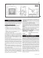
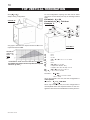
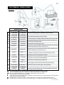
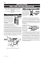
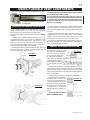
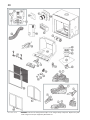
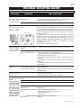
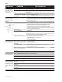
1
W415-0447 / B / 05.24.05
W415-0447 / B / 05.24.05
2
WARNINGS & SAFETY PRECAUTIONS
WHAT TO DO IF YOU SMELL GAS
W415-0447 / B / 05.24.05
3
TABLE of CONTENTS
PG2-6
INTRODUCTION
20
Warnings and Safety Precautions
Warranty
Dimensions
General Instructions
General Information
Care of Glass & Plated Parts
6-11
21
REMOTE AND VALVE ACCESS
Remote Removal
Valve Removal
22-24
OPERATION / MAINTENANCE
Fireplace Operation
Hand Held Remote Operation
Operating Instructions
Maintenance
VENTING
Vent lengths
Venting Specifications
Air Terminal Locations
12-17
BLOWER REPLACEMENT
INSTALLATION/FRAMING
Wall & Ceiling Protection
Using Flexible Vent Components
Fireplace Vent Connection
Using Rigid Vent Components
Gas Installation
Restricting Vertical Vents
Framing
Clearance to Combustibles
Mantle Clearances and Enclosures
24
ADJUSTMENTS
Pilot Burner Adjustment
Venturi Adjustment
Air Control Rod Access
25-26
17
ELECTRICAL CONNECTION
18-20
FINISHING
REPLACEMENTS
Ordering Replacement Parts
Replacement Parts
Terminal Kits
Vent Kits
Accessories
Schematic
27-28
TROUBLE SHOOTING GUIDE
Door Removal
Log Shipping Bracket Removal
Log Placement
Baffle Installation
Charcoal Embers
Lamp Replacement
PLEASE RETAIN THIS MANUAL FOR FUTURE REFERENCE
WARNING
• Do not burn wood or other materials in this fireplace.
• Adults and especially children should be alerted to the hazards of high surface temperatures and should stay away to
avoid burns or clothing ignition. Supervise young children when they are in the same room as the fireplace.
• Due to high temperatures, the fireplace should be located out of traffic and away from furniture and draperies.
• Clothing or other flammable material should not be placed on or near the fireplace.
• Any safety screen or guard removed for servicing must be replaced prior to operating the fireplace.
• It is imperative that the control compartments, burners and circulating blower and its passageway in the fireplace and
venting system are kept clean. The fireplace and its venting system should be inspected before use and at least
annually by a qualified service person. More frequent cleaning may be required due to excessive lint from carpeting,
bedding material, etc. The fireplace area must be kept clear and free from combustible materials, gasoline and other
flammable vapours and liquids.
• Under no circumstances should this fireplace be modified.
• This fireplace must not be connected to a chimney flue pipe serving a separate solid fuel burning appliance.
• Do not use this fireplace if any part has been under water. Immediately call a qualified service technician to inspect the
fireplace and to replace any part of the control system and any gas control which has been under water.
• Do not operate the fireplace with the glass door removed, cracked or broken. Replacement of the glass should be
done by a licensed or qualified service person.
• Do not strike or slam shut the fireplace glass door.
• This fireplace uses and requires a fast acting thermocouple. Replace only with a fast acting thermocouple supplied by
Wolf Steel Ltd.
NOTE: CHANGES, OTHER THAN EDITORIAL, ARE DENOTED BY A VERTICAL LINE IN THE MARGIN.
W415-0447 / B / 05.24.05
4
NAPOLEON gas fireplaces are manufactured under the strict Standard of the world recognized
ISO 9001 : 2000 Quality Assurance Certificate.
NAPOLEON products are designed with superior components and materials, assembled by trained craftsmen
who take great pride in their work. The burner and valve assembly are leak and test-fired at a quality test station.
The complete fireplace is thoroughly inspected by a qualified technician before packaging to ensure that you, the
customer, receives the quality product that you expect from NAPOLEON.
NAPOLEON GAS FIREPLACE PRESIDENT'S LIFETIME LIMITED WARRANTY
The following materials and workmanship in your new napoleon gas fireplace are warranted against defects for as long as
you own the fireplace. This covers: combustion chamber, heat exchanger, stainless steel burner, PHAZER™ logs and
embers, ceramic glass (thermal breakage only), gold plated parts against tarnishing, porcelainized enamelled components
and aluminum extrusion trims.
Electrical (110V and millivolt) components and wearable parts such as the blower, gas valve, thermal switch, switches,
wiring, remote control, ignitor, gasketing, and pilot assembly are covered and NAPOLEON will provide replacement parts
free of charge during the first year of the limited warranty. Light bulbs are not covered by this warranty.
Labour related to warranty repair is covered free of charge during the first year. Repair work, however, requires the prior
approval of an authorized company official. Labour costs to the account of NAPOLEON are based on a predetermined rate
schedule and any repair work must be done through an authorized NAPOLEON dealer.
CONDITIONS AND LIMITATIONS
NAPOLEON warrants its products against manufacturing defects to the original purchaser only -- i.e., the individual or legal entity (registered customer)
whose name appears on the warranty registration card filed with NAPOLEON -- provided that the purchase was made through an authorized NAPOLEON
dealer and is subject to the following conditions and limitations:
This factory warranty is nontransferable and may not be extended whatsoever by any of our representatives.
The gas fireplace must be installed by a licenced, authorized service technician or contractor. Installation must be done in accordance with the installation
instructions included with the product and all local and national building and fire codes.
This limited warranty does not cover damages caused by misuse, lack of maintenance, accident, alterations, abuse or neglect and parts installed from
other manufacturers will nullify this warranty.
This limited warranty further does not cover any scratches, dents, corrosion or discolouring caused by excessive heat, abrasive and chemical cleaners nor
chipping on porcelain enamel parts, mechanical breakage of PHAZER™ logs and embers, nor any venting components used in the installation of the
fireplace.
NAPOLEON warrants its stainless steel burners against defects in workmanship and material for life, subject to the following conditions: During the first 10
years NAPOLEON will replace or repair the defective parts at our option free of charge. From 10 years to life, NAPOLEON will provide replacement burners
at 50% of the current retail price.
In the first year only, this warranty extends to the repair or replacement of warranted parts which are defective in material or workmanship provided that the
product has been operated in accordance with the operation instructions and under normal conditions.
After the first year, with respect to this President's Limited Lifetime Warranty, NAPOLEON may, at its discretion, fully discharge all obligations with respect
to this warranty by refunding to the original warranted purchaser the wholesale price of any warranted but defective part(s).
After the first year, NAPOLEON will not be responsible for installation, labour or any other costs or expenses related to the reinstallation of a warranted
part, and such expenses are not covered by this warranty.
Notwithstanding any provisions contained in this President's Limited Lifetime Warranty, NAPOLEON’S responsibility under this warranty is defined as
above and it shall not in any event extend to any incidental, consequential or indirect damages.
This warranty defines the obligations and liability of NAPOLEON with respect to the NAPOLEON gas fireplace and any other warranties expressed or
implied with respect to this product, its components or accessories are excluded.
NAPOLEON neither assumes, nor authorizes any third party to assume, on its behalf, any other liabilities with respect to the sale of this product. NAPOLEON will not be responsible for: over-firing, downdrafts, spillage caused by environmental conditions such as rooftops, buildings, nearby trees, hills,
mountains, inadequate vents or ventilation, excessive venting configurations, insufficient makeup air, or negative air pressures which may or may not be
caused by mechanical systems such as exhaust fans, furnaces, clothes dryers, etc.
Any damages to fireplace, combustion chamber, heat exchanger, brass trim or other component due to water, weather damage, long periods of dampness, condensation, damaging chemicals or cleaners will not be the responsibility of NAPOLEON.
The bill of sale or copy will be required together with a serial number and a model number when making any warranty claims from your authorized dealer.
The warranty registration card must be returned within fourteen days to register the warranty.
NAPOLEON reserves the right to have its representative inspect any product or part thereof prior to honouring any warranty claim.
ALL SPECIFICATIONS AND DESIGNS ARE SUBJECT TO CHANGE WITHOUT PRIOR NOTICE DUE TO ON-GOING PRODUCT IMPROVEMENTS. NAPOLEON® IS A REGISTERED
TRADEMARK OF WOLF STEEL LTD. PATENTS U.S. 5.303.693.801 - CAN. 2.073.411, 2.082.915. © WOLF STEEL LTD.
W415-0447 / B / 05.24.05
5
FIGURE 1
GENERAL INSTRUCTIONS
THIS GAS FIREPLACE SHOULD BE INSTALLED AND SERVICED BY A QUALIFIED INSTALLER to conform with local
codes. Installation practices vary from region to region and it
is important to know the specifics that apply to your area,
for example: in Massachusetts State:
• The fireplace damper must be removed or welded in the
open position prior to installation of a fireplace insert or
gas log.
• The appliance off valve must be a “T” handle gas cock.
• The flexible connector must not be longer than 36 inches.
• The appliance is not approved for installation in a bedroom or
bathroom unless the unit is a direct vent sealed combustion prod
uct.
• WARNING: This product must be installed by a licensed
plumber or gas fitter when installed within the
commonwealth of Massachusetts.
In absence of local codes, install to the current CAN/CGA B149 Installation Code in Canada or to the National Fuel Gas
Code, ANSI Z223.1, and NFPA 54 in the United States. Suitable for mobile home installation if installed in accordance
with the current standard CAN/CSA Z240MH Series, for gas
equipped mobile homes, in Canada or ANSI Z223.1 and NFPA
54 in the United States.
The fireplace and its individual shutoff valve must be disconnected from the gas supply piping system during any pressure testing of that system at test pressures in excess of 1/2
psig (3.5 kPa). The fireplace must be isolated from the gas
supply piping system by closing its individual manual shutoff
valve during any pressure testing of the gas supply piping
system at test pressures equal to or less than 1/2 psig (3.5
kPa).
When the fireplace is installed directly on carpeting, vinyl tile
or other combustible material other than wood flooring, the
fireplace shall be installed on a metal or wood panel extending the full width and depth.
The optional heat circulating blower is supplied with a cord. If
installed, the junction box must be electrically connected and
grounded in accordance with local codes. In the absence of
local codes, use the current CSA C22.1 CANADIAN ELECTRICAL CODE in Canada or the ANSI/NFPA 70 NATIONAL
ELECTRICAL CODE in the United States.
Purge all gas lines with the glass door of the fireplace open.
Assure that a continuous gas flow is at the burner before
closing the door.
Under extreme vent configurations, allow several minutes
(5-15) for the flame to stabilize after ignition.
Provide adequate ventilation and combustion air. Provide
adequate accessibility clearance for servicing and operating the fireplace. Never obstruct the front opening of the
fireplace.
Objects placed in front of the fireplace must be kept a
minimum of 48" from the front face of the unit.
Minimum clearance to combustible construction
from fireplace and vent surfaces:
fireplace framing - 0" to stand-offs (top, rear and sides)
fireplace finishing - 5 3/8" to sides,
23 3/8" to top of fireplace opening.
vent pipe
- 2 inches
recessed depth
- 29 inches
GENERAL INFORMATION
FOR YOUR SATISFACTION, THIS FIREPLACE HAS BEEN
TEST-FIRED TO ASSURE ITS OPERATION AND QUALITY!
Maximum input is 43,000 BTU/hr for both natural gas and propane. When the fireplace is installed at elevations above 4,500ft,
and in the absense of specific recommendations from the local
authority having jurisdiction, the certified high altitude input rating shall be reduced at the rate of 4% for each additional 1,000ft.
Maximum output for natural gas is 33,540 BTU/hr at an efficiency of 78%; and 34,000 BTU/hr for propane at an efficiency
of 79%. Minimum inlet gas supply pressure is 4.5 inches water
column for natural gas and 11 inches water column for propane.
Maximum inlet gas pressure is 7 inches water column for natural gas and 13 inches water column for propane. Manifold pressure under flow conditions is 3.5 inches water column for natural gas and 10 inches water column for propane.
This fireplace is approved for bathroom, bedroom and bedsitting room installations and is suitable for mobile home installation. The natural gas model can only be installed in a
mobile home that is permanently positioned on its site and
fueled with natural gas.
W415-0447 / B / 05.24.05
6
This fireplace may be installed in an aftermarket
permanently located, manufactured (mobile) home, where
not prohibited by local codes.
This fireplace is only for use with the type of gas indicated
on the rating plate. This fireplace is not convertible for use
with other gases, unless a certified kit is used.
No external electricity (110 volts or 24 volts) is required for
the gas system operation.
Expansion / contraction nosies during heating up and cooling
down cycles are normal and are to be expected. Change in
flame appearance from "HI" to "LO" is more evident in natural
gas than in propane.
CARE OF GLASS, AND PLATED PARTS
Do not use abrasive cleaners to clean plated parts. Buff
lightly with a clean dry cloth. The glass is 3/16" ceramic
glass available from your Napoleon / Wolf Steel Ltd. dealer.
DO NOT SUBSTITUTE MATERIALS. Clean the glass after
the first 10 hours of operation with a recommended gas
fireplace glass cleaner. Thereafter clean as required. DO
NOT CLEAN GLASS WHEN HOT! If the glass is not kept
clean permanent discolouration and / or blemishes may
result.
VENTING
VENTING LENGTHS & AIR TERMINAL LOCATIONS
Use only Wolf Steel, Simpson Dura-Vent, Selkirk Direct Temp
or American Metal Amerivent venting components.
For Simpson Dura-Vent, Selkirk Direct Temp and American
Metal Amerivent, follow the installation procedure provided
with the venting components.
All outer pipe joints of these venting systems must be sealed
using Red RTV Hight Temperature Sealant.
Wolf Steel, Simpson Dura-Vent, Selkirk Direct Temp and
American Metal Amerivent venting systems must not be
combined.
A starter adaptor must be used and may be purchased from
the corresponding supplier:
Supplier
5&8 ZC
Duravent
W175-0170
Amerivent
4DSC-N2
Direct Temp
5DT-AAN
When using Napoleon venting components, use only approved Wolf Steel Ltd. rigid / flexible vent components with
the following termination kits: WALL TERMINAL KIT GD422R,
or 1/12 TO 7/12 PITCH ROOF TERMINAL KIT GD410, 8/12
TO 12/12 ROOF TERMINAL KIT GD411, FLAT ROOF TERMINAL KIT GD412 or PERISCOPE KIT GD401 (for wall penetration below grade). With flexible venting, in conjunction
with the various terminations, use either the 5 foot vent kit
GD420 or the 10 foot vent kit GD430. These vent kits allow
for either horizontal or vertical venting of the fireplace.
The maximum allowable vertical vent length is 40 feet.
The maximum number of allowable 5" vent connections is
three horizontally or vertically (excluding the fireplace and
the air terminal connections).
For optimum flame appearance and fireplace performance,
keep the vent length and number of elbows to a minimum.
The air terminal must remain unobstructed at all times.
Examine the air terminal at least once a year to verify that it
is unobstructed and undamaged.
When venting, the horizontal run must be kept to a minimum of 16 inches or a maximum of 20 feet. If a 20 foot
horizontal run is required, the fireplace must have a minimum vertical rise immediately off the fireplace of 57
inches. FIGURES 2a-c. When terminating vertically, the
vertical rise is a minimum 34 inches and a maximum 40
feet above the fireplace. FIGURE 3.
W415-0447 / B / 05.24.05
FIGURES 2A-C
FIGURE 3
Horizontal runs may have a 0 inch rise per foot in all cases
using SIMPSON DURA-VENT or NAPOLEON RIGID OR
FLEXIBLE venting components when venting as
illustrated in Figures 2a, 2b, and 2c.
For optimum performance, it is recommended that all
horizontal runs have a minimum ¼ inch rise per foot.
Provide a means for visually checking the vent connection to the fireplace after the fireplace is installed.
Do not allow the inside liner to bunch up on horizontal or
vertical runs and elbows. Keep it pulled tight. A 1¼" air
gap between the inner and outer liner all around is
required for safe operation.
Vent lengths that pass through unheated spaces (attics,
garages, crawl space) should be wrapped with a protective insulation sleeve to minimize condensation.
Use a firestop when penetrating interior walls, floor or
ceiling.
For safe and proper operation of the fireplace follow the
venting instruction exactly.
Deviation from the minimum vertical vent length can create difficulty in burner start-up and/or carboning.
If vertical rises greater than 57 inches are necessary,
the increased rise must be deducted from the horizontal run.
7
DEFINITIONS
for the following symbols used in the venting calculations
and examples are:
> - greater than
> - equal to or greater than
< - less than
< - equal to or less than
HT - total of both horizontal vent lengths (HR) and offsets
(HO) in feet
HR - combined horizontal vent lengths in feet
HO - offset factor: .03(total degrees of offset - 90°*) in
feet
VT - combined vertical vent lengths in feet
ELBOW VENT LENGTH VALUES
1°
15°
30°
45°
90°*
feet
0.03
0.45
0.9
1.35
2.7
inches
0.5
6.0
11.0
16.0
32.0
* the first 90° offset has a zero value and is shown in the
formula as -90°
TOP EXIT / HORIZONTAL TERMINATION
when (HT) < (VT)
Simple venting configuration (only one 90° elbow)
For vent configurations requiring more than one 90° elbow,
the following formulas apply:
Formula 1: HT < VT
Formula 2: HT + VT < 40 feet
90°
Example 1:
H2
FIGURE 4
V2
FIGURE 5
90°
H1
See graph to determine the required vertical rise VT for the
required horizontal run HT.
90°
V1
VERTICAL
RISE
IN
FEET
VT
HORIZONTAL VENT RUN PLUS OFFSET IN FEET HT
The shaded area within the lines represents acceptable
values for HT and VT .
V1
V2
VT
H1
H2
HR
HO
HT
=
=
=
=
=
=
=
=
3 ft
8 ft
V1 + V2 = 3 + 8 = 11 ft
2.5 ft
2 ft
H1 + H2 = 2.5 + 2 = 4.5 ft
.03(three 90° elbows - 90°) = .03(270° - 90°) = 5.4 ft
HR + HO = 4.5 + 5.4 = 9.9 ft
HT + VT = 9.9 + 11 = 20.9 ft
Formula 1:
HT < VT
9.9 < 11
Formula 2: HT + VT < 40 feet
20.9 < 40
Since both formulas are met, this vent configuration is
acceptable.
W415-0447 / B / 05.24.05
8
TOP EXIT / HORIZONTAL TERMINATION
when (HT) > (VT)
Simple venting configuration (only one 90° elbow)
Example 3:
90°
H4
H1
FIGURE 6
H2
See graph to determine the required vertical rise VT for the required horizontal run
HT.
V1
90°
V2
H3
FIGURE 8
V1
V2
VT
H1
H2
H3
H4
HR
HO
HT
HT + VT
REQUIRED
VERTICAL
RISE IN
INCHES
VT
HORIZONTAL VENT RUN PLUS OFFSET IN FEET HT
The shaded area within the lines represents acceptable
values for HT and VT .
For vent configurations requiring more than one 90° elbow
the following formulas apply:
Formula 1: HT < 4.2 VT
Formula 2: HT + VT < 24.75 feet
H2
V1
90°
FIGURE 7
V1
=
H1
=
H2
=
HR
=
HO
=
HT
=
HT + VT =
VT = 6 ft
3 ft
5 ft
H1 + H2 = 3 + 5 = 8 ft
.03(two 90° elbows - 90°) = .03(180° - 90°) = 2.7 ft
HR + HO = 8 + 2.7 = 10.7 ft
10.7 + 6 =16.7
Formula 1:
HT < 4.2 VT
Formula 2:
10.7 < 25.2
HT + VT < 24.75 feet
16.7 < 24.75
4.2 VT = 4.2 x 6 = 25.2 ft
Since both formulas are met, this vent configuration is acceptable.
W415-0447 / B / 05.24.05
4 ft
1.5 ft
V1 + V2 = 4 + 1.5 = 5.5 ft
2 ft
1 ft
1 ft
1.5 ft
H1 + H2 + H3 + H4 = 2 + 1 + 1 + 1. 5 = 5.5 ft
.03(four 90° elbows - 90°) = .03(360° - 90°) = 8.1 ft
HR + HO = 5.5 + 8.1 = 13.6 ft
13.6 + 5.5 = 19.1 ft
Formula 1: HT < 4.2 VT
4.2 VT = 4.2 x 5.5 = 23.1 ft
13.6 < 23.1
Formula 2: HT + VT < 24.75 feet
19.1 < 24.75
Since both formulas are met, this vent configuration is
acceptable.
H1
Example 2:
=
=
=
=
=
=
=
=
=
=
=
9
TOP EXIT VERTICAL TERMINATION
when (HT) < (VT)
Simple venting configurations
FIGURE 9
REQUIRED
VERTICAL RISE
IN FEET
VT
HORIZONTAL VENT RUN PLUS OFFSET IN FEET HT
The shaded area within the lines represents acceptable
values for HT and VT .
See graph to determine the required vertical rise VT for the
required horizontal run HT.
For vent configurations requiring more than zero 90° elbow
(top exit) or one 90° elbow (rear exit), the following formulas
apply:
Formula 1: HT < VT
Formula 2: HT + VT < 40 feet
W415-0447 / B / 05.24.05
10
TOP VERTICAL TERMINATION
when (HT) > (VT)
Simple venting configurations
For vent configurations requiring more than two 90° elbow
(top exit) or one 90° elbow (rear exit), the following formulas
apply:
FIGURE 10
Formula 1: HT < 3VT
Formula 2: HT + VT < 40 feet
Example 7:
90°
V1
90°
H1
V2
H2
90°
See graph to determine the required vertical rise VT for the
required horizontal run HT.
MAXIMUM
VERTICAL
RISE IN
FEET
VT
HORIZONTAL VENT RUN PLUS OFFSET IN FEET HT
The shaded area within the lines represents acceptable
values for HT and VT .
V3
90°
FIGURE 11
= 2 ft
= 1 ft
= 1.5 ft
= V1 + V2 + V3 = 2 + 1 + 1.5 = 4.5 ft
= 6 ft
= 2 ft
= H1 + H2 = 6 + 2 = 8 ft
= .03(four 90° elbows - 90°)
= .03(90 + 90 + 90 + 90 - 90) = 8.1 ft
HT
= HR + HO = 8 + 8.1 = 16.1 ft
HT + VT = 16.1 + 4.5 = 20.6 ft
V1
V2
V3
VT
H1
H2
HR
HO
Formula 1:
HT < 3VT
3VT = 3 x 4.5 = 13.5 ft
16.1 > 13.5
Since this formula is not met, this vent configuration is
unacceptable.
Formula 2: HT + VT < 40 feet
20.6 < 40
Since only formula 2 is met, this vent configuration is
unacceptable and a new fireplace location or vent configuration will need to be established to satisfy both for-
W415-0447 / B / 05.24.05
11
AIR TERMINAL INSTALLATIONS
FIGURE 12
INSTALLATIONS
CANADIAN
U.S.A.
A
12 INCHES
12 INCHES
Clearance above grade, veranda porch, deck or balcony.
B
12 INCHES
9 INCHES
Clearance to windows or doors that open.
C
12 INCHES*
12 INCHES*
Clearance to permanently closed windows.
D
18 INCHES**
18 INCHES**
Vertical clearance to ventilated soffit located above the terminal within
a horizontal distance of 2 feet from the centerline of the terminal.
E
12 INCHES**
12 INCHES**
Clearance to unventilated soffit.
F
0 INCHES
0 INCHES
0 INCHES***
0 INCHES***
Clearance to an inside non-combustible corner wall or protruding
non-combustible obstructions (chimney, etc.).
2 INCHES***
2 INCHES***
Clearance to an inside combustible corner wall or protruding combustible obstructions ( vent chase, etc.).
H
3 FEET
3 FEET****
Clearance to each side of the centerline extended above the meter
/ regulator assembly to a maximum vertical distance of 15ft.
I
3 FEET
3 FEET****
Clearance to a service regulator vent outlet.
J
12 INCHES
9 INCHES
Clearance to a non-mechanical air supply inlet to the building or a
combustion air inlet to any other appliance.
K
6 FEET
3 FEET†
L
7 FEET‡
7 FEET****
M
12 INCHES††
12 INCHES****
N
16 INCHES
16 INCHES
O
2 FEET†*
2 FEET†*
G
*
**
***
****
†
‡
††
†*
Clearance to an outside corner wall.
Clearance to a mechanical air supply inlet.
Clearance above a paved sidewalk or paved driveway located on
public property unless fitted with a heat shield kit GD-301.
Clearance under a veranda, porch, deck or balcony.
Clearance above the roof.
Clearance from an adjacent wall including neighbouring buildings.
Recommended to prevent condensation on windows and thermal breakage
It is recommended to use a heat shield and to maximize the distance to vinyl clad soffits.
The periscope GD-201 requires a minimum 18 inches clearance from an inside corner.
This is a recommended distance. For additional requirements check local codes.
Three feet above if within 10 feet horizontally.
A vent shall not terminate directly above a sidewalk or paved driveway that is located between two single family
dwellings and serves both dwellings.
Permitted only if the veranda, porch, or deck is fully open on a minimum of two sides beneath the floor.
Recommenced to prevent recirculation of exhaust products. For additional requirements check local codes.
W415-0447 / B / 05.24.05
12
INSTALLATION
WALL AND CEILING PROTECTION
FOR SAFE AND PROPER OPERATION OF THE FIREPLACE, FOLLOW THE VENTING INSTRUCTIONS
EXACTLY.
A 2” CLEARANCE IS REQUIRED AROUND THE
VENT PIPE.
HORIZONTAL INSTALLATION
This application occurs when
FIGURE 13
venting through an exterior
wall. Having determined the air 13"
ROUND OR
terminal location, cut and frame
12.500" SQUARE HOLE
a hole in an exterior wall. The
recommended framed opening
is 147/16" W x 13" H with a mini147/16"
mum 121/ 2" round or square
opening inside a finished wall.
See figure15.
16.000"c/c
1. Mark and cut the vent pipe
shield to the determined depth of
the combustible wall. Apply a bead of
caulking (not supplied) to the framework or
to the shield plate (in the case of a finished wall) and secure
the shield through the opening to the interior wall. The final
location of the vent pipe shield should maintain the required
clearance to the 8" vent pipe / liner. (See note above). Do not
fill this cavity with any type of material. Apply a bead of caulking all around and place a firestop spacer over the vent shield
to restrict cold air from being drawn into the room or around
the fireplace. Ensure that both spacer and shield maintain
the required clearance to combustibles. Once the vent
pipe / liner is installed in its final position, apply sealant between the pipe / liner and the firestop spacer.
OR
FIGURE 14
SHOWN FROM INSIDE THE STRUCTURE
W415-0447 / B / 05.24.05
VERTICAL INSTALLATION
This application occurs
when venting through a
roof. Installation kits for
various roof pitches are
available from your Napoleon dealer. See Accessories to order the specific kit required.
FIGURE 15
1. Determine the air terminal location, cut and frame
147/16" W x 13" H openings in the ceiling and the roof to provide the minimum 2 inch clearance between the fireplace
pipe / liner and any combustible material. Try to centre the
exhaust pipe location midway between two joist to prevent
having to cut them. Use a plumb bob to line up the centre of
the openings. DO NOT FILL THIS SPACE WITH ANY TYPE
OF MATERIAL.
A vent pipe
shield will prevent
any materials such
as insulation, from
filling up the 1" air FIGURE 16
space around the
pipe. Nail headers
between the joist
for extra support.
2. Apply a bead of caulking (not supplied) to the framework or to the Wolf Steel vent pipe shield plate or equivalent
(in the case of a finished ceiling), and secure over the opening in the ceiling. A firestop must be placed on the bottom of
each framed opening in a roof or ceiling that the venting system passes through. Apply a bead of caulking all around
and place a firestop spacer over the vent shield to restrict
cold air from being drawn into the room or around the fireplace. Ensure that both spacer and shield maintain the required clearance to combustibles. Once the vent pipe / liner
is installed in its final position, apply sealant between the pipe
/ liner and the firestop spacer.
13
USING FLEXIBLE VENT COMPONENTS
Use only approved aluminum flexible liner kits
marked:
"Wolf Steel Approved Venting" as
identified by the stamp only on the
8” outer liner.
HORIZONTAL AIR TERMINAL INSTALLATION
1. Cut or frame a hole in an exterior wall with a minimum
round or square opening of 121/2" W x 121/2" H. Secure the
firestop spacer over the opening to the interior wall.
Secure the terminal to the terminal extension plate (see figure 19).
2. Stretch the 5" diameter aluminum flexible liner to the
required length taking into account the additional length
needed for the finished wall surface. Slip the liner a minimum of 2" over the inner sleeve of the air terminal and secure with 3 #8 screws. Apply a heavy bead of the high temperature sealant (W573-0007 not provided).
3. Using the 8" diameter flexible aluminum liner, slide over
the outer combustion air sleeve of the air terminal and secure with 3 #8 screws. Seal as before.
FIGURE 17
FIGURE 18
For safe and proper operation of the fireplace, follow
the venting instructions exactly.
All inner exhaust and outer intake vent pipe joists may
be sealed using either Red RTV high temp silicone sealant or Black high temp Mill Pac with the exception of the
fireplace exhaust flue collar which must be sealed using
Mill Pac (not supplied).
4. Insert the liners through the firestop maintaining the
required clearance to combustibles. Secure to the exterior
wall and make weather tight by sealing with caulking (not
supplied).
5. Apply a heavy bead of the high temperature sealant, not
supplied with the unit, to the inside of the 5" liner approximately 1" from the end. Slip the liner a minimum of 2" over
the fireplace vent collar and secure with 3 #8 screws.
6. Using the 8" diameter flexible aluminium liner, apply sealant, slide a minimum of 2" over the fireplace combustion air
collar and secure with 3 #8 screws.
VERTICAL AIR TERMINAL INSTALLATION
1. Fasten the roof support to the
FIGURE 19
roof using the screws provided.
The roof support is optional.
In this case the venting is to
be adequately supported
using either an alternate
method suitable to the authority having jurisdiction
or the optional roof support.
2. Stretch the 5" diameter aluminium flexible liner to the
required length. Slip the liner a minimum of 2" over the inner
sleeve of the air terminal and secure with 3 #8 screws. Seal
using a heavy bead of the high temperature sealant (W5730007 not supplied).
3. Repeat using 8" diameter aluminium flexible liner.
4. Thread the air terminal pipe
assembly down through the
FIGURE 20
roof. The air terminal must be
located vertically and plumb. Attach the air terminal assembly
to the roof support, ensuring that
a minimum 16" of air terminal
will penetrate the roof when fastened.
DO NOT CLAMP THE FLEXIBLE ALUMINIUM LINER.
W415-0447 / B / 05.24.05
14
5. Remove nails from the shingles, above and to the sides
of the chimney. Place the flashing over the air terminal and
slide it underneath the sides and upper edge of the shingles.
Ensure that the air terminal is properly centred within the flashing, giving a 3/4" margin all around. Fasten to the roof. Do
not nail through the lower portion of the flashing. Make
weather-tight by sealing with caulking. Where possible, cover
the sides and top edges of the flashing with roofing material.
6. Apply a heavy bead of weatherproof caulking 2 inches
above the flashing. Slide the storm collar around the air terminal and down to the caulking. Tighten to ensure that a
weather-tight seal between the air terminal and the collar is
achieved. Attach the other storm collar centred between the
air intake and the air exhaust slots onto the air terminal. Tighten
securely. Attach the vertical rain cap.
Spacers are attached to the 5" inner flex liner at predetermined intervals to
maintain a 1-1/4" air
gap to the 8" outer
liner. These spacers
must not be removed.
7. If more liner needs to be used to reach the fireplace, couple
them together as illustrated. The vent system must be supported approximately every 3 feet for both vertical and horizontal runs. Use noncombustible strapping to maintain a clearance
to combustibles of 1".
FIREPLACE VENT CONNECTION
1. Install the 5 inch diameter aluminium flexible liner to the
fireplace. Secure with 3 screws and flat washers. Seal the
joint and screw holes using the high temperature sealant
(W573-0007 not provided).
2. Install the 8 inch diameter aluminium flexible liner to the
fireplace. Attach and seal the joints.
FIGURE 22
FIGURE 21
USING RIGID VENT COMPONENTS
The vent system must be supported approximately every 3
feet for both vertical and horizontal runs. Use Wolf Steel vent
spacers or equivalent every 3 feet and either side of each
elbow to maintain the minimum 1¼" clearance between the
outer and inner vent pipes. Use Wolf Steel support ring assembly or equivalent noncombustible strapping to maintain
the minimum clearance to combustibles for both vertical and
horizontal runs.
All inner exhaust and outer intake vent pipe joists may
be sealed using either Red RTV high temp silicone sealant or Black high temp Mill Pac with the exception of the
fireplace exhaust flue collar which must be sealed using
Mill Pac (not supplied).
2. Apply high temperature sealant (W573-0007 not provided) to the outer edge of the 5" inner collar of the fireplace.
Attach the first vent component and secure using 3 self tapping screws. Repeat using 8" piping.
3. Holding the air terminal (with the air deflectors to the top
and the lettering in an upright, readable position) insert the
terminal into both vent pipes with a twisting motion to ensure that
both the terminal sleeves engage into the vent pipes and sealant. Secure the terminal to the exterior wall and make weather
tight by sealing with caulking (not supplied).
HORIZONTAL AIR TERMINAL INSTALLATION
1. Follow the instructions for "Horizontal Air Terminal Installations", items 1 to 3.
2. Continue adding components alternating inner and outer
venting. Ensure that all 5" venting and elbows have sufficient
vent spacers attached and each component is securely fastened to the one prior. Attach the 5" telescopic sleeve to the
vent run.
Repeat using a 8" telescopic sleeve. Secure
and seal as before. To facilitate completion, attach 5" and 8" couplers
to the air terminal.
FIGURE 23
1. Move the fireplace into position. Measure the vent length required
between terminal and fireplace taking into account the
additional length needed for the finished wall surface and any
1¼" overlaps between venting components.
W415-0447 / B / 05.24.05
EXTENDED HORIZONTAL AIR TERMINAL
INSTALLATION
3. Install the air terminal. See item
3 of the Horizontal Air Terminal Installation. Extend the 5" telescopic
sleeve; connect to the air terminal
assembly. Fasten with self tapping
screws and seal. Repeat using the
8" telescopic sleeve.
FIGURE 24
15
VERTICAL VENTING INSTALLATION
1. Move the fireplace into position.
2. Fasten the roof support to the roof using the screws
provided. The roof support is optional. In this case the venting is to be adequately supported using either an alternate
method suitable to the authority having jurisdiction or the optional roof support.
3. Apply high temperature sealant (W573-0007 not provided) to the outer edge of the inner sleeve of the air terminal.
Slip a 5" diameter coupler a minimum of 2" over the sleeve
and secure using 3 screws.
FIGURE 25
4. Apply high temperature sealant
to the outer edge of the of the outside sleeve of the air terminal. Slip a
8" diameter coupler over the sleeve
and secure as before. Trim the 8"
coupler even with the 5" coupler end.
5. Thread the air terminal pipe
assembly down through the roof
support and attach, ensuring that
a minimum 16" of air terminal will
penetrate the roof when fastened.
If the attic space is tight, we recommend threading the Wolf Steel
vent pipe collar or equivalent
loosely onto the air terminal assembly as it is passed through
the attic. The air terminal must be
FIGURE 26
located vertically and plumb.
6. Remove nails from the shingles, above and to the sides
of the chimney. Place the flashing over the air terminal and
slide it underneath the sides and upper edge of the shingles.
Ensure that the air terminal is properly centred within the
flashing, giving a 3/4" margin all around. Fasten to the roof.
Do NOT nail through the lower portion of the flashing. Make
weather-tight by sealing with caulking. Where possible, cover
the sides and top edges of the flashing with roofing material.
7. Apply a heavy bead of waterproof caulking 2 inches
above the flashing. Slide the storm collar around the air terminal and down to the caulking. Tighten to ensure that a
weather-tight seal between the air terminal and the collar is
achieved. Attach the other storm collar centred between the
air intake and air exhaust slots onto the air terminal. Tighten
securely. Attach the rain cap.
8. Continue adding rigid venting sections, sealing and
securing as above. Attach a 5" collapsed telescopic pipe to
the last section of rigid piping. Secure with screws and seal.
Repeat using a 8" telescopic pipe.
9. Run a bead of high temperature sealant around the
outside of the 5" collar on the fireplace. Pull the adjustable
pipe a minimum of 2" onto the collar. Secure with 3 screws.
Repeat with the 8" telescopic pipe.
10. In the attic, slide the vent pipe collar down to cover up
the open end of the shield and tighten. This will prevent any
materials, such as insulation, from filling up the 1" air space
around the pipe.
GAS INSTALLATION
Proceed once the vent installation is complete.
Note : All gas connections must be contained within
the fireplace when complete.
FIGURE 27
1. The fireplace is designed to accept a ½"
gas supply line. The
fireplace is equipped
with a ½" manual
shut-off valve, and an 18" listed flexible gas connector.
FIGURE 28
2. The access to the gas inlet is located on the right side
of the outer shell.
3. To ease the connection,
the shut off can be flexed out
through the side of the fireplace where the connection
can be made.
4. When flexing any gas line, support the gas valve so that
the lines are not bent. (see Access Pg. 20).
5. Check for gas leaks by brushing on a soap and water
solution. Do not use open flame.
RESTRICTING VERTICAL VENTS
TOP OF THE
FIREBOX
RESTRICTOR PLATE
FLUE COLLAR
FIGURE 29
Vertical terminations may display a very active flame. If this
appearance is not desirable, the vent exit must be restricted
using restrictor plate, W500-0205. This reduces the velocity
of the exhaust gases, slowing down the flame pattern and
creating a more traditional appearance.
The plate has a series of holes to allow for adjustment.
Remove the two screws on either side of the exhaust collar
inside the firebox. Install the plate in the desired set of holes,
then replace the screws.
W415-0447 / B / 05.24.05
16
CLEARANCE TO COMBUSTIBLES
FRAMING
The Madison can be installed with either an arched opening
(FK80-A) or a rectangular opening (FK80-R) using one of
the above kits.
The framing kits serve two purposes. They are necessary if
optional doors (DK80) are to be installed.
Secondly, they act as a reference when finishing to the fireplace opening.
The FK80 is designed to accomodate 1/2” to 1 1/2” finishing
material. They are adjustable to ensure doors open fully .
If finishing material is thicker than 1 1/2”, an optional extension kit is available (EK80).
It is best to frame your fireplace after it is positioned and the
vent system is installed. Use 2x4's and frame to local building codes.
Note: In order to avoid the possibility of exposed insulation
or vapour barrier coming in contact with the fireplace body, it
is recommended that the walls of the fireplace enclosure
be “finished” (ie: drywall/sheetrock), as you would finish any
other outside wall of a home. This will ensure that clearance
to combustibles is maintained within the cavity.
For convenience, the stand-offs have been shipped flat.
Before framing, ensure the stand-offs are opened and
screwed in place.
It is not necessary to install a hearth extension, but the fireplace should be raised to be flush with either the hearth or
the finished floor.
When roughing in the fireplace, raise the fireplace to accommodate for the thickness of the finished floor materials,
i.e. tile, carpeting, hard wood, which if not planned for will
interfere with the removal of the hearth strip, which must be
removed to access the firebox.
Objects placed in front of the fireplace should be kept a
minimum of 48" away from the front face.
MAINTAIN THESE MINIMUM CLEARANCES TO COMBUSTIBLES:
Fireplace framing - 0" to stand-offs (top, rear & sides)
Fireplace finishing - 5 3/8” to sides of fireplace opening.
- 23 3/8” to top of fireplace opening.
FIGURE 32
Non-combustible finishing
material (ie: cement board,
brick, stone,
tile) may be
used to finish
the front of the
unit.
IMPORTANT:
The Madison requires a
minimum inside enclosure
height of 72”.
For temperature requirements, this area must be left
unobstructed.
It is recommended that the
enclosure be ventilated at
the top and bottom to circulate the hot air.
FIGURE 30
FIGURE 33
WARNING
Facing and/or finishing
material must never
overhang into the fireplace
opening.
FIGURE 31
Do not distort or force the frame
kit components.
When using a rough finish
material (i.e.; stone), maintain a
¼” - ½” border from the framing
components.
W415-0447 / B / 05.24.05
17
MANTLE CLEARANCES
Combustible mantle clearance can vary according to the
mantle depth. Use the graph to help evaluate the clearance
needed.
FIGURE 34
ELECTRICAL CONNECTION
Do NOT use the fireplace if any part has been under
water.
Call a qualified service technician IMMEDIATELY to have
the fireplace inspected for damage to the electrical
circuit.
If access to the control area is necessary BEFORE
INSTALLATION, remove the access panel.
The access panel must be re-installed before operating
the unit.
HARD WIRING CONNECTION
It is necessary to hard wire this fireplace.
Permanently framing the fireplace with an enclosure, requires the fireplace junction box to be hardwired.
This fireplace must be electrically connected and grounded
in accordance with local codes. In the absence of local codes,
use the current CSA C22.1 CANADIAN ELECTRICAL CODE
in Canada or the ANSI/NFPA 70-1996 NATIONAL ELECTRICAL CODE in the United States.
SCHEMATIC
FIGURE 35
W415-0447 / B / 05.24.05
18
FINISHING
FIGURE 38
DOOR REMOVAL
FIGURE 36
Before the glass door can be removed, the control doors
must be removed and the hearth strip and screen assembly
must be removed.
FIGURE 37
The glass door is secured to the top front edge of the firebox. Pull the handle of the latch forward, then lift the hook out
from the slot in the door frame to release the top of the door.
Lift the door out from the retainer along the bottom of the
door using the top and bottom handles. Pull the bottom
edge of the door out from the fireplace until the top will pivot
forward.
LOG SHIPPING BRACKET
FIGURE 39
LOG SHIPPING
BRACKET
Lift the hearth strip up and away from the front of the fireplace. The curtain assembly can be removed by lifting the
rod out from the three hooks at the top inside edge of the
door opening.
W415-0447 / B / 05.24.05
Before installing the logs, you must first remove the log shipping bracket. Lift up to remove.
19
Decorative brick panels must be installed before the logs.
See installation instructions supplied with the panel kit.
LOG PLACEMENT
PHAZER logs, exclusive to Napoleon Fireplaces, provide
a unique and realistic glowing effect that is different in every
installation. The madison logs are fuel specific. Do not
interchange. Refer to the replacement parts list.
TM
4
FIGURE 40a-f
1
4. Place log #4, with the charred branch pointed inward.
Locate the pins into the holes in log#1 and log#2, this will
hold the rear log in position.
1. Place the rear log #1 onto the locating studs along the
back edge of the PHAZERAMIC™ burner.
5
2
5. Place the end of log #5 on the right end of log #1. The fork
in the log should straddle the knot on top of log #2.
2. Position log #2 onto the locators on the PHAZERAMIC™
burner.
3
3. Position the slot on the bottom of log #3 onto the bracket
shown with the charred face of the log to the front.
GLOWING EMBERS
Glowing embers are NOT recommended. The burner has
been designed to achieve maximum glow without embers.
BAFFLE INSTALLATION
Your fireplace has been supplied with the decorative brick
panels installed, however, it is necessary to install the fibre
baffle, on top of the side and rear panels.
CHARCOAL EMBERS
Charcoal provided could be randomly placed on the fibre
hearth on both sides of the burner, and across the front, especially at the hearth joint.
Log colours may vary. During the initial use of the fireplace, the colours will become more uniform as colour
pigments burn in during the heat activated curing process.
Positioning the logs improperly will cause flame impingement and carboning.
Blocked burner ports can cause an incorrect flame pattern,
carbon deposits and delayed ignition. PHAZERTM logs glow
when exposed to direct flame. Use only certified PHAZERTM
logs available from your Napoleon dealer.
Note
For propane, remove the
screw from the #3 log support
bracket. Move the bracket to
the right most location, then
install the log.
BRACKET
W415-0447 / B / 05.24.05
20
LAMP REPLACEMENT
1. Turn off the power to the unit.
2. Turn off the gas valve.
3. Remove the door and logs.
FIGURE 42
FIGURE 41
4. Loosen the lense retainer screws and pivot the retainers
out of the way.
5. Using a small flat screwdriver, gently lift the orange lense
from the housing.
6. Slide the defective bulb to either side until the opposite
end is disengaged. Remove the bulb lifting the disengaged
end.
7. Replace with a 75 watt halogen lamp (E-11 BASE).
Install the replacement bulb using the protective wrap
to avoid touching the lense, then disgard the protective wrap.
8. Repeat steps 5 - 1 for installation.
BLOWER REPLACEMENT
The Napoleon MADISON comes equipped with a heat circulating blower. The blower is pre-wired and is controlled by
the remote control supplied with the unit. For control details,
see operation. Pg . 22.
Drywall dust will penetrate into the blower bearings,
causing irreparable damage. Care must be taken to prevent drywall dust from coming into contact with the
blower or its compartment. Any damage resulting from
this condition is not covered by the warranty policy.
1. Turn off the power to the fireplace.
FIGURE 43
2. Turn off the gas valve.
FIGURE 44
4. To remove the lamp assembly, remove the two log locating studs located just behind the main burner. It is not necessary to disconnect the wires, the assembly can lay along the
right side of the firebox.
FIGURE 45
3. Remove the glass door, logs, rear log support, side brick
panels, rear baffle, and rear panel.
5. The blower mounting plate can now be removed. Remove
the six screws that secure the plate to the firebox back. The
blower is secured to this plate.
6. Disconnect the wire connectors and ground before attempting to remove the blower from the plate.
7. When re-installing the replacement blower, it will be necessary to replace the gasket (W290-0091) on the cover plate.
W415-0447 / B / 05.24.05
21
REMOTE AND VALVE ACCESS
INNER ACCESS DOOR
The control area can be accessed either through the control
door or through the access door inside the firebox.
Follow the door removal instructions. Remove the right side
panel. Remove the four screws from the access door.
Note: A new gasket will be required, when re-installing
the door (see replacement parts).
FIGURE 47
CONTROL DOOR
1. Remove
hearth strip.
the
2. Open the right
control door.
3. Remove the
switch plate by pulling on the left side.
4. Remove the valve
housing by pulling on
the handle.
5. Lift up and set the
housing towards the
back of the fire
place.
FIGURE 46
FIGURE 48
REMOTE RECEIVER REMOVAL
1. Unplug the cord from the junction box
2. Pull the the tab on the receiver lock forward.
3. Pull up on the receiver and disconnect the wires.
4. Install the new receiver (see schematic Pg.23).
VALVE REMOVAL
The valve on the Madison is piped with two flex connectors
(one inlet, one outlet).
It can be removed or pulled forward for service.
1. Remove the wing nut and pivot the valve out from the slot
at the bottom of the valve.
2. Slowly pull the valve through the control door careful not
to kink the gas lines or wires.
W415-0447 / B / 05.24.05
22
OPERATION / MAINTENANCE
FIREPLACE OPERATION
To operate the gas fireplace, the pilot needs to be running
and the gas valve turned to the on position.
You can run the fireplace on manual or remote.
When operating the main burner on manual without
power, the fireplace will operate on low input only.
Turn the main power switch to
FIGURE 49
manual to operate the gas features
of the fireplace in the event of a
power failure.
Turn the main power switches to
remote to operate with the gas and
the electric features of the fireplace
with the remote or thermostat.
With power, the manual position
operates the same as the remote position with the exception
of the ability to turn off the gas.
Turn the main power switch to the off position to disable both
the gas and the electric features of the fireplace.
To configure the remote transmitter to the receiver, see
“Privacy Code”.
HAND HELD REMOTE OPERATION
FIGURE 50
1. Turns accent light on/off.
2. Turns gas flame on/off.
3. Activates gas flame
adjustment.
4. Activates fan adjustment.
5. Adjusts options #3 & #4 up.
6. Sets the timer.
7. Adjusts options #3 & #4 down.
8. Sets the time.
MANUAL / THERMOSTAT OPERATION
Thermostatic control automatically cycles the fireplace on and
off to maintain the desired room temperature. To turn the
fireplace burner on, press the gas button. The LCD will display
the “Auto” / “OFF” status. Set the desired room temperature
using the up or down arrow keys. If the temperature of
the room exceeds the set temperature, the
thermostat will automatically turn t he fireplace
off.
Note: If a blower is connected, the thermostatic control will
also turn off the blower when the fireplace is turned off.
TO SET THE TIME
Press and hold the CLOCK button until the hour flashes.
Adjust the hour using the up or down keys. Press the CLOCK
button again to confirm the hour and change to minutes.
Again, adjust the minutes using the up or down keys. Finally,
press the CLOCK button twice to confirm the settings and
return to normal, operating mode.
W415-0447 / B / 05.24.05
TIMER OPERATION
The timer setting is used to maintain the desired room
temperature for a specific length of time (1 to 120 minutes)
that you want the fireplace to operate.
Press the TIMER button once. The LCD will blink "_ _ _".
Adjust the time using the up or down arrow keys. (The LCD
displays the time chosen.) Press the TIMER button to engage
the timer. (When time has expired, the LCD switches to off
and displays "_ _ _".)
FLAME HEIGHT
1. With “Auto” displayed, pushing the button marked "flame
height" will display a flame image and the current flame
setting.
2. Use “UP” “DOWN” buttons to choose 3 different flame
levels:1,2,3.
FAN SPEED
1. Pushing the button marked "fan speed" will display a fan
image.
2. Use “UP” “DOWN” buttons to choose 3 different fan levels:1,2,3.
PRIVACY CODE
1. Remove the cover on the back of the
remote transmitter to expose the code
switches. Slide the code switches to your
choice of ON or OFF positions. Factory
settings are all "OFF".
2. Remove power from the remote CODE SWITCHES
receiver by unplugging the power cord or turning power off
at the circuit breaker.
3. Take the remote transmitter close to the remote receiver
(less than 5 feet from the remote receiver is recommended).
4. Turn on the remote receiver.
5. Install fresh AAA alkaline batteries into the remote transmitter. The LCD on the remote transmitter will blink.
6. Press a button on the remote transmitter. The remote receiver will produce a "beep" sound when it receives the code
from the remote transmitter.
7. If you do not hear a "beep" sound from the remote receiver,
remove batteries from the remote transmitter and power from
the remote receiver. Wait for 1 minute and repeat steps 3 to
6.
8. Replace the cover of the remote transmitter and the
receiver. The system is now ready to operate.
9. If you desire to operate multiple remote receivers with
one remote transmitter, continue to hold the button on the
remote transmitter as you bring the remote transmitter within
5 feet of each remote receiver then slide the switch on the
remote receivers to ON position. Each will acknowledge
receipt of coding with a beep.
CHILD-PROOF FUNCTION
When used in this mode, the remote transmitter will work
normally but the buttons will be disabled.
Remove the cover at the back of the Remote Transmitter to
expose the Child-Proof switch. To activate this function, slide
the switch to the position marked C/P. "*Child-Proof*" will
appear on the LCD.
23
To restore button function temporarily, press the Up and
Down buttons in the following sequence:
up-down-down-up-down.
If no button is pressed within 2 minutes, the transmitter will
return to the Child-Proof mode.
IN THE EVENT OF A POWER FAILURE
To operate the fireplace manually in the event of a power/
battery failure, the main power switch located in the fireplace, may be switched to the manual position.
Once power has been restored, it will be necessary to
reset the remote. Resetting is done either by pushing
the red reset button on the receiver or manually cycling
the gas button on the transmitter. This is done by removing the batteries from the transmitter.
Re-install the batteries after 1 minute. Press any button
while holding the transmitter within 5 feet of the fireplace.
The receiver will emit a “beep” sound to confirm programming has been successful.
OPERATING INSTRUCTIONS
When lit for the first time, the fireplace will emit a slight
odour for a few hours. This is a normal temporary condition
caused by the curing of the logs and the "burn-in" of internal
paints and lubricants used in the manufacturing process
and will not occur again. Simply open a window to sufficiently
ventilate the room.
After extended periods of non-operation such as following a
vacation or a warm weather season, the fireplace may emit
a slight odour for a few hours. This is caused by dust particles in the heat exchanger burning off. Open a window to
sufficiently ventilate the room.
Purge all gas lines with the glass door of the fireplace
open. Assure that a continuous gas flow is at the
burner before closing the door.
FOR YOUR SAFETY READ BEFORE LIGHTING:
A. This fireplace is equipped with a pilot which must be
lit by hand while following these instructions exactly.
B. Before operating smell all around the fireplace area
for gas and next to the floor because some gas is
heavier than air and will settle on the floor.
C. Use only your hand to turn the gas control knob /
manual shut-off knob. never use tools. if the knob
will not turn by hand, do not try to repair it. call a
qualified service technician. force or attempted re
pair may result in a fire or explosion.
D. Do not use this fireplace if any part has been under
water. immediately call a qualified service technician
to inspect the fireplace and replace any part of the
control system and any gas control which has been
under water.
WHAT TO DO IF YOU SMELL GAS
•
•
•
•
•
•
Do not touch any electric switch.
Do not use any phone in your building.
If you cannot reach your gas supplier, call the fire
department.
Turn off all gas to the fireplace.
Do not try to light any appliance.
Immediately call your gas supplier from a
neighbor's phone. Follow the gas supplier's instruct
ions.
FIGURE 51
GAS KNOB
LIGHTING INSTRUCTIONS
Warning: if you do not follow these instructions exactly, a
fire or explosion may result causing property damage,
personal injury or loss of life. Initial lighting of the pilot and
main burners must be done with the glass door off.
Do not connect valve or wall switch to electricity. See installation instructions.
When lighting and re-lighting, the gas knob cannot be
turned from pilot to off unless the knob it depressed slightly.
1. STOP! read the safety information on the operating
label.
2. Turn off all electric power to the fireplace.
to off.
3. Turn the gas knob clockwise
4. Wait 5 minutes to clear out any gas. If you smell gas,
including near the floor, STOP! Follow "B" on the op
erating label. If you don't smell gas, go to the next
step.
5. If the fireplace is equipped with a flame adjustment
valve, turn clockwise to off.
6. Find pilot located infront of the back log on the right
side.
to pilot.
7. Turn gas knob counter-clocwise
8. This unit is equipped with an auto-spark.
Depress and hold gas knob . Keep knob fully depressed
for one minute, then release. If pilot does not continue
to burn repeat steps 3 through 7.
9. With pilot lit, turn gas knob counter-clockwise
to on.
10. If equipped with flame adjustment valve, push
and turn knob to high.
11. If equipped with remote on-off switch, main burner
may not come on when you turn the valve to on or
high. Remote switch must be in the on position to ignite
burner.
12.Turn on all electric power to
the fireplace.
FIGURE 52
TO TURN OFF GAS
1. Turn off all electric power to the fireplace if service is to
be performed.
2. For a complete shut-down procedure: push in gas conto off. Do not
trol knob slightly and turn clockwise
force.
3. For a temporary shut-down procedure: set thermostat
to lowest setting or remote switch to off. Press and turn
the gas knob clockwise
to pilot.
W415-0447 / B / 05.24.05
24
MAINTENANCE
TURN OFF THE GAS AND ELECTRICAL POWER
BEFORE SERVICING THE FIREPLACE.
CAUTION: Label all wires prior to disconnection when servicing controls. Wiring errors can cause improper and dangerous operation. Verify proper operation after servicing. This
fireplace and its venting system should be inspected before
use and at least annually by a qualified service person. The
fireplace area must be kept clear and free of combustible
materials, gasoline or other flammable vapours and liquids.
The flow of combustion and ventilation air must not be obstructed.
1. In order to properly clean the burner and pilot assembly, remove the logs to expose both assemblies.
2. Keep the control compartment, logs, burner, air shutter opening and the area surrounding the logs clean
by vacuuming or brushing, at least once a year.
3. Check to see that all burner ports are burning. Clean
out any of the ports which may not be burning or are
not burning properly.
4. Check to see that the pilot flame is large enough to
engulf the thermocouple and thermopile and reaches
toward the burner with the third jet.
5. Replace the cleaned logs.
6. Check to see that the main burner ignites completely
on all openings when the gas knob for the burner is
turned on. A 5 to 10 second total light-up period is
satisfactory. If ignition takes longer, consult your Napoleon dealer / distributor.
7. Check that the gasketing on the sides, top and bottom of the door is not broken or missing. Replace if
necessary.
ADJUSTMENTS
PILOT BURNER ADJUSTMENT
Adjust the pilot screw to provide properly sized flame. Turn
in a clockwise direction to reduce the gas flow.
VENTURI ADJUSTMENT
Air Shutter Openings
LP
NG
FIGURE 53
3
/8"
/16"
3
Closing the air shutter will cause a more yellow flame, but
can lead to carboning. Opening the air shutter will cause a
more blue flame, but can cause flame lifting from the burner
ports. The flame may not appear yellow immediately; allow
15 to 30 minutes for the final flame colour to be established.
FIGURE 55
FIGURE 54
AIR CONTROL ROD ACCESS
1. Remove the glass door.
2. Remove the logs.
3. Remove the air deflector / light housing (Pg. 19)
(It is not necessary to disconnect the wires. The assembly
can lay along the right side of the firebox).
4. The air control rod can now be adjusted. Pushing the rod
towards the back will open the air shutter (larger hole, larger
opening), pulling the rod towards the front will close the
shutter (smaller hole, smaller opening).
FIGURE 56
W415-0447 / B / 05.24.05
25
REPLACEMENTS
Contact your dealer for questions concerning prices and
availability of replacement parts. Normally all parts can be
ordered through your Napoleon dealer or distributor.
When ordering replacement parts always give the following
information:
FOR WARRANTY REPLACEMENT PARTS, A PHOTOCOPY OF THE
ORIGINAL INVOICE WILL BE REQUIRED TO HONOUR THE CLAIM.
REPLACEMENT PARTS
#
PART NO. DESCRIPTION
1
2
3
4
5
6
7
8
9*
10
10
11
11
12
13
14
15
15
16
16
17*
18*
19
20
21
22
23
24
25
26*
27
28
29*
30
31
32*
33*
34*
35
36
37
W135-0205
W135-0206
W135-0207
W135-0208
W135-0218
GL-644
GL-647
W135-0021
W390-0002
W725-0044
W725-0045
W455-0024
W455-0056
W680-0014
W240-0005
W680-0015
W010-1194
W010-1201
W455-0070
W455-0068
W385-0245
W562-0008
W500-0028
W100-0081
W062-0010
W660-0041
W660-0030
W660-0031
W190-0017
W715-0629
W185-0020
W010-1203
W010-1289
W300-0073
W565-0078
W750-0126
W290-0091
W120-0054
W387-0005
W500-0206
W290-0099
#1 - REAR LOG
#2 - MIDDLE LOG - NG
#3 - RIGHT LOG
#4 - LEFT LOG
#5 - CROSSOVER LOG
LOG SET ASSEMBLY - NG
LOG SET ASSEMBLY - LP
#2 - MIDDLE LOG - LP
DOOR LATCH (EA)
NATURAL GAS VALVE - MODULATING
PROPANE GAS VALVE - MODULATING
#30 NATURAL GAS ORIFICE
#50 PROPANE GAS ORIFICE
THERMOCOUPLE
ELECTRODE C/W LEAD
THERMOPILE
NATURAL GAS PILOT ASSEMBLY
PROPANE GAS PILOT ASSEMBLY
NG PILOT INJECTOR
LP PILOT INJECTOR
NAPOLEON LOGO
DOOR GASKET (132 INCHES)
FIRESTOP (2 INCH CLEARANCE)
BURNER
BLOWER
SPARK SWITCH
REMOTE TRANSMITTER
REMOTE RECEIVER
DC SPARK UNIT CONTROL
CAST IRON TRIM
CAST GRATE
DOOR FRAME
GLASS C/W GASKET
GLASS DIFUSER
SCREEN
WIRE HARNESS LIGHT SOCKET
BLOWER MOUNTING GASKET
CURTAIN ROD CAP
LAMP
TERMINAL EXTENSION PLATE
ACCESS DOOR GASKET
1.
2.
3.
4.
5.
MODEL & SERIAL NUMBER OF FIREPLACE
INSTALLATION DATE OF FIREPLACE
PART NUMBER
DESCRIPTION OF PART
FINISH
* IDENTIFIES ITEMS WHICH ARE NOT ILLUSTRATED. FOR
FURTHER INFORMATION, CONTACT YOUR NAPOLEON
DEALER.
FLEXIBLE VENT KITS
GD420 (5 FT)
38*
W010-0772
38*
W730-0012
5" FLEXIBLE ALUMINIUM LINER
- (5 FT) C/W SPACERS
8" FLEXIBLE ALUMINIUM LINER - (5 FT)
GD430 (10 FT)
38*
38*
W730-0013
W010-0773
8" FLEXIBLE ALUMINIUM LINER - (10
5" FLEXIBLE ALUMINIUM LINER
- (10 FT) C/W SPACERS
WALL SUPPORT ASSEMBLY
39*
W010-0810
40
41
PERISCOPE
WALL TERMINAL KIT
42
43
44
45
46
47
48
49
1/12 TO 7/12 PITCH
8/12 TO 12/12 PITCH
FLAT ROOF
W010-0774
AIR TERMINAL
W120-0015
VERTICAL CAP
W170-0086
STORM COLLAR
W010-0453
ROOF SUPPORT
W263-0065 /
ROOF FLASHING
W263-0066 /
W263-0067
FT)
TERMINAL KITS
GD401
- GD422R
ROOF TERMINAL KITS
- GD410
- GD411
- GD412
ACCESSORIES
50*
51*
52
53
54
55*
56*
57*
58*
58*
59
60
61
62
61
62
63
63
63
63
W573-0007
GD501
GA-566
GA-72
GA-70
W010-0370
W175-0166
W175-0002
W175-0229
W175-0230
FK80-R
FK80-A
DK80A-HC
DK80R-HC
DK80A-HP
DK80R-HP
GD800-KT
GD806-KT
GD807-KT
PRP80
HI-TEMP SEALANT
HEAT GUARD
HOT AIR DISTRIBUTION KIT
HOT AIR EXHAUST KIT
EXTENSION KIT, 5FT FLEX VENT
WALL SUPPORT ASSEMBLY
5" COUPLER
8" COUPLER
CONVERSION KIT - NG TO LP
CONVERSION KIT - LP TO NG
FRAMING KIT - RECTANGULAR
FRAMING KIT - ARCHED
DECORATIVE DOORS-HAMMERED COPPER-ARCHED
DECORATIVE DOORS-HAMMERED COPPER-RECTANGULAR
DECORATIVE DOORS-HAMMERED PEUTER-ARCHED
DECORATIVE DOORS-HAMMERED PEUTER-RECTANGULAR
OLD TOWN RED BRICK KIT
HERRINGBONE/SANDSTONE BRICK KIT
SANDSTONE BRICK KIT
PORCELAIN REFLECTIVE PANELS BRICK KIT
W415-0447 / B / 05.24.05
26
W415-0447 / B / 05.24.05
* WARNING: This is a fast acting thermocouple. It is an integral safety component. Replace only with
a fast acting thermocouple supplied by Wolf Steel Ltd.
27
TROUBLE SHOOTING GUIDE
BEFORE ATTEMPTING TO TROUBLESHOOT, PURGE YOUR UNIT AND INITIALLY LIGHT THE PILOT AND THE MAIN BURNER WITH THE GLASS DOOR OPEN.
SYMPTOM
PROBLEM
Main burner flame Blockage in vent.
is a blue, lazy,
transparent flame.
Incorrect installation.
TEST SOLUTION
- remove blockage. In really cold conditions, ice buildup may occur on
the terminal and should be removed as required.
- refer to Figure 13 to ensure correct location of storm collars.
Flames are consis- Unit is over-fired or under- - check pressure readings:
tently too large or fired.
Inlet pressure can be checked by turning screw (A) counter-clockwise
too
small.
2 or 3 turns and then placing pressure gauge tubing over the test point.
Carboning occurs.
Gauge should read 7" (minimum 4.5") water column for natural gas or
13" (11" minimum) water column for propane. Check that main burner
is operating on "HI".
Outlet pressure can be checked the same as above using screw (B).
Gauge should read 3.5" water column for natural gas or 10" water
column for propane. Check that main burner is operating on "HI".
AFTER TAKING PRESSURE READINGS, BE SURE TO TURN
SCREWS CLOCKWISE FIRMLY TO RESEAL. DO NOT
OVERTORQUE.
Leak test with a soap and water solution.
Carbon is being de- Air shutter has become
posited on glass, blocked
logs or combustion
chamber surfaces. Flame is impinging on the
logs or combustion chamber.
- ensure air shutter opening is free of lint or other obstructions.
- check that the logs are correctly positioned.
- open air shutter to increase the primary air.
- check the input rate: check the manifold pressure and orifice size as
specified by the rating plate values.
- check that the door gasketing is not broken or missing and that the
seal is tight.
- check that both 4" and 7" vent liners are free of holes and well sealed
at all joints.
- check that minimum rise per foot has been adhered to for any horizontal venting.
White / grey film Sulphur from fuel is being de- - clean the glass with a gas fireplace glass cleaner. DO NOT CLEAN
forms.
posited on glass, logs or com- GLASS WHEN HOT.
bustion chamber surfaces.
If deposits are not cleaned off regularly, the glass may become permanently marked.
Exhaust fumes Fireplace is spilling.
smelled in room,
headaches.
Pilot goes out when
the gas knob is released.
The gas valve has
an interlock device
which will not allow the pilot
burner to be lit until the thermocouple has cooled.
Allow approximately 60 seconds
for the thermocouple to cool.
- check door seal and relief flap seal.
- check for chimney blockage
- check that the paint curing process is complete
System is not correctly - purge the gas line with the glass door open.
purged.
Out of propane gas.
- fill the tank.
Pilot flame is not large enough - turn up the pilot flame.
Pilot flame is not engulfing the - gently twist the pilot head to improve the flame pattern around the
thermocouple.
thermocouple.
Thermocouple shorting / faulty.
Faulty valve.
loosen and tighten thermocouple.
clean thermocouple and valve connection.
replace thermocouple.
replace valve.
- replace.
W415-0447 / B / 05.24.05
28
SYMPTOM
PROBLEM
Pilot burning; no Themostat or switch is defecgas to main burner; tive.
gas knob is on 'HI'; Wall switch wiring is defecwall switch / ther- tive.
mostat is on.
TEST SOLUTION
- connect a jumper wire across the wall switch terminals; if main burner
lights, replace switch / thermostat.
- disconnect switch wires &connect a jumper wire across terminals 1
& 3; if the main burner lights, check the wires for defects and / or replace wires.
Main burner orifice is plugged.
- remove stoppage in orifice.
Faulty valve.
- replace.
Pilot goes out while Gas piping is undersized.
standing; Main
burner is in 'OFF'
position.
- turn on all gas appliances and see if pilot flame flutters, diminishes or
extinguishes, especially when main burner ignites. Monitor appliance
supply working pressure.
- check if supply piping size is to code. Correct all undersized piping.
Pilot will not light.
No spark at pilot burner
-
Out of propane gas
- fill the tank.
Spark gap is incorrect
- spark gap should be 0.150" to 0.175" (5/32" to 11/64" approx.) from
the electrode tip and the pilot burner. To ensure proper electrode location, tighten securing nut (finger tight plus 1/4 turn).
No gas at the pilot burner
-
check if pilot can be lit by a match
check that the wire is connected to the push button ignitor.
check if the push button ignitor needs tightening.
replace the wire if the wire insulation is broken or frayed.
replace the electrode if the ceramic insulator is cracked or broken.
replace the push button ignitor.
check that the manual valve is turned on.
check the pilot orifice for blockage.
replace the valve.
call the gas distributor.
Main burner goes Pilot flame is not large - turn up pilot flame.
out; pilot stays on. enough or not engulfing the - replace pilot assembly.
thermopile
Thermopile shorting
- clean thermopile connection to the valve. Reconnect.
- replace thermopile / valve.
Remote wall switch wire is too - shorten wire to correct length or wire gauge.
long; too much resistance in
the system.
Faulty thermostat or switch.
- replace.
Main burner goes Refer to "MAIN BURNER GOES OUT; PILOT STAYS ON"
out; pilot goes out.
- check for vent blockage.
Vent is blocked
Vent is re-circulating
- check joint seals and installation.
4" flexible vent has become - re-attach to fireplace.
disconnected from fireplace.
Remote wall switch
is in "OFF" position;
main burner comes
on when gas knob is
turned to "ON" position.
W415-0447 / B / 05.24.05
Wall switch is mounted up- - reverse.
side down
Remote wall switch is - replace.
grounding.
Remote wall switch wire is - check for ground (short); repair ground or replace wire.
grounding.
- replace.
Faulty valve.