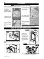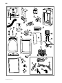
1
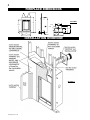
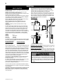
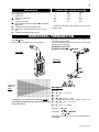
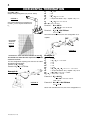
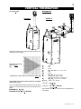
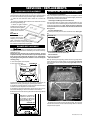
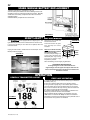
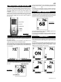
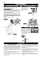
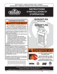
1
INSTALLER: LEAVE THIS MANUAL WITH THE APPLIANCE
CONSUMER: RETAIN THIS MANUAL FOR FUTURE REFERENCE
INSTALLATION AND
OPERATION INSTRUCTIONS
CERTIFIED UNDER CANADIAN AND AMERICAN NATIONAL STANDARDS: CSA 2.33, ANSI Z21.88 FOR VENTED GAS FIREPLACE HEATERS.
GD82NT-PA
NATURAL GAS
GD82PT-PA
PROPANE
CERTIFIED FOR CANADA AND UNITED STATES USING ANSI/CSA METHODS.
SAFETY INFORMATION
!
WARNING
If the information in these instructions are
not followed exactly, a fire or explosion may
result causing property damage, personal
injury or loss of life.
- Do not store or use gasoline or other
flammable vapors and liquids in the vicinity of
this or any other appliance.
- WHAT TO DO IF YOU SMELL GAS:
Do not try to light any appliance.
Do not touch any electrical switch; do
not use any phone in your building.
Immediately call your gas supplier from a
neighbour’s phone. Follow the gas
supplier’s instructions.
If you cannot reach your gas supplier, call
the fire department.
- Installation and service must be
performed by a qualified installer, service
agency or the supplier.
Wolf Steel Ltd., 24 Napoleon Rd., Barrie, ON L4M 4Y8 Canada • (705)721-1212 • fax(705)722-6031
www.napoleonfireplaces.com • [email protected]
$10.00
W415-0665
/ B / 02.11.08
W415-0665
/ B / 02.11.08
2
TABLE of CONTENTS
PG2-5
Log Shipping Bracket
Decorative Brick Panel Installation
Log Placement
Glowing Embers
AFK / WI FACE KIT Installation
INTRODUCTION
Warranty
Fireplace Dimensions
Installation Overview
General Instructions
General Information
Care of Glass
6-11
21-22
Glass / Door Replacement
Blower Replacement
Burner and Valve Replacement
Spark Module Battery Replacement
Night LightTM Replacement
VENTING
Vent lengths
Venting Specifications
Minimum Air Terminal Location Clearances
12-18
INSTALLATION
Wall & Ceiling Protection
Horizontal Installation
Vertical Installation
Using Flexible Vent Components
Horizontal Air Terminal Installation
Vertical Air Terminal Installation
Fireplace Vent Connection
Using Rigid Vent Components
Horizontal Air Terminal Installation
Extended Horizontal Air Terminal Installation
Vertical Air Terminal Installation
Mobile Home
Gas Installation
Restricting Vertical Vents
Minimum Framing Clearances
Minimum Enclosure Clearances
Minimum Mantel and Enclosure Clearances
18
19-20
22-24
25
26
OPERATING INSTRUCTIONS
ADJUSTMENTS
Maintenance
Pilot Burner Adjustment
Flame Characteristics
Venturi Adjustment
27-28
REPLACEMENTS
Ordering Replacement Parts
Replacement Parts
Flexible Vent Kits
Terminal Kits
Roof Terminal Kits
Accessories
29-30
31
32
FINISHING
OPERATION
Fireplace Operation
Hand Held Remote Operation
Operating Instructions
ELECTRICAL CONNECTION
Hard Wiring Connections
Electrical Schematic
SERVICING / REPLACEMENTS
TROUBLE SHOOTING GUIDE
FIREPLACE SERVICE HISTORY
NOTES
Door Removal
PLEASE RETAIN THIS MANUAL FOR FUTURE REFERENCE
!
WARNING
• Do not burn wood or other materials in this fireplace.
• Adults and especially children should be alerted to the hazards of high surface temperatures and should stay away to avoid
burns or clothing ignition. Supervise young children when they are in the same room as the fireplace.
• Clothing or other flammable material should not be placed on or near the fireplace.
• Due to high temperatures, the fireplace should be located out of traffic and away from furniture and draperies.
• Ensure you have incorporated adequate safety measure to protect infants/toddlers from touching hot surfaces.
• Even after the fireplace is out, the glass and/or screen will remain hot for an extended period of time.
• Check with your local hearth specialty dealer for safety screens and hearth guards to protect children from hot surfaces. These
screens and guards must be fastened to the floor.
• Any safety screen or guard removed for servicing must be replaced prior to operating the fireplace.
• It is imperative that the control compartments, burners and circulating blower and its passageway in the fireplace and venting
system are kept clean. The fireplace and its venting system should be inspected before use and at least annually by a qualified
service person. More frequent cleaning may be required due to excessive lint from carpeting, bedding material, etc. The fireplace
area must be kept clear and free from combustible materials, gasoline and other flammable vapours and liquids.
• Under no circumstances should this fireplace be modified.
• This fireplace must not be connected to a chimney flue pipe serving a separate solid fuel burning appliance.
• Do not use this fireplace if any part has been under water. Immediately call a qualified service technician to inspect the fireplace
and to replace any part of the control system and any gas control which has been under water.
• Do not operate the fireplace with the glass door removed, cracked or broken. Replacement of the glass should be done by a
licensed or qualified service person.
• Do not strike or slam shut the fireplace glass door.
• This fireplace uses and requires a fast acting thermocouple. Replace only with a fast acting thermocouple supplied by Wolf
Steel Ltd.
• Pressure relief doors must be kept closed while the fireplace is operating to prevent exhaust fumes containing carbon monoxide, from entering into the home. Temperatures of the exhaust escaping through these openings can also cause the surrounding
combustible materials to overheat and catch fire.
• Only doors / optional fronts certified with the unit are to be installed on the appliance.
W415-0665 / B / 02.11.08
NOTE: Changes, other than editorial, are denoted by a vertical line in the margin.
3
®
®
®
®
The following materials and workmanship in your new NAPOLEON® gas fireplace are warranted against
defects for as long as you own the fireplace. This covers: combustion chamber, heat exchanger, stainless steel
burner, phazer™ logs and embers, gold plated parts against tarnishing, porcelainized enameled components and
aluminum extrusion trims.
Electrical (110V and millivolt) components and wearable parts such as blowers, gas valves, thermal switch,
switches, wiring, remote controls, ignitor, gasketing, and pilot assembly are covered and NAPOLEON® will
provide replacement parts free of charge during the first year of the limited warranty.
Labour related to warranty repair is covered free of charge during the first year. Repair work, however, requires
the prior approval of an authorized company official. Labour costs to the account of NAPOLEON® are based on
a predetermined rate schedule and any repair work must be done through an authorized NAPOLEON® dealer.
®
®
®
®
®
®
®
®
®
®
®
®
®
W415-0665 / B / 02.11.08
4
FIREPLACE DIMENSIONS
58"
FIGURE 1
46"
17 / "
34
37 5/8"
4" DIA.
7" DIA.
1
21" 22 /8"
5"
2"
24"
28"
13 7/8"
/"
78
8 7/8"
14"
GAS INLET
28"
INSTALLATION OVERVIEW
FIGURE 2
W415-0665 / B / 02.11.08
5
GENERAL INSTRUCTIONS
This gas fireplace should be installed and serviced by a qualified
installer to conform with local codes. Installation practices vary
from region to region and it is important to know the specifics that
apply to your area,
for example: in Massachusetts State:
• The fireplace damper must be removed or welded in the open
position prior to installation of a fireplace insert or gas log.
• The appliance off valve must be a “T” handle gas cock.
• The flexible connector must not be longer than 36 “.
• The appliance is not approved for installation in a bedroom or
bathroom unless the unit is a direct vent sealed combustion
product.
• A carbon monoxide detector is required in all rooms containing
gas fired appliances.
• WARNING: This product must be installed by a licensed
plumber or gas fitter when installed within the commonwealth of
Massachusetts.
In absence of local codes, install to the current CAN/CGA -B149
Installation Code in Canada or to the National Fuel Gas Code,
ANSI Z223.1, and NFPA 54 in the United States. Suitable for
mobile home installation if installed in accordance with the current
standard CAN/CSA Z240MH Series, for gas equipped mobile
homes, in Canada or ANSI Z223.1 and NFPA 54 in the United
States.
The fireplace and its individual shutoff valve must be disconnected from the gas supply piping system during any pressure
testing of that system at test pressures in excess of 1/2 psig (3.5
kPa). The fireplace must be isolated from the gas supply piping
system by closing its individual manual shutoff valve during any
pressure testing of the gas supply piping system at test
pressures equal to or less than 1/2 psig (3.5 kPa).
When the fireplace is installed directly on carpeting, vinyl tile or
other combustible material other than wood flooring, the fireplace
shall be installed on a metal or wood panel extending the full
width and depth.
The optional heat circulating blower is supplied with a cord. If
installed, the junction box must be electrically connected and
grounded in accordance with local codes. In the absence of local
codes, use the current CSA C22.1 canadian electrical code in
Canada or the ANSI/NFPA 70 national electrical code in the
United States.
Provide adequate ventilation and combustion air.
Provide adequate accessibility clearance for servicing and
operating the fireplace. Never obstruct the front opening of
the fireplace.
Objects placed in front of the fireplace must be kept a
minimum of 48” from the front face of the unit.
This fireplace is only for use with the type of gas indicated on the
rating plate. This fireplace is not convertible for use with other
gases, unless a certified kit is used.
Expansion / contraction noises during heating up and cooling
down cycles are normal and are to be expected. Change in flame
appearance from “HI” to “LO” is more evident in natural gas than
in propane.
This fireplace is approved for bathroom, bedroom and bed-sitting
room installations and is suitable for mobile home installation.
We
Suggest
thatwill
our
gas with
The inner stainless steel
looking
firebox back
discolour
heat, turning a light brown,
straw products
like colour that
to be considhearth
beisinstalled
ered normal.
and serviced by professionals who are certified in the
We Suggest that our gas
U.S. by the National Firehearth products be installed
place Institute (NFI) as NFI
and serviced by professionGas Specialists.
als who are certified in the
U.S. by the National FireCARE
GLASS
placeOF
Institute
(NFI) as NFI
Do not use abrasive cleaners
clean glass. Buff lightly with a
Gas to
Specialists.
clean dry cloth. The glass is 3/16” ceramic glass available from
your Napoleon® / Wolf Steel Ltd. dealer. Do not substitute
materials. Clean theCARE
glass after
the GLASS
first 10 hours of operation with
OF
a recommended gas fireplace glass cleaner. Thereafter clean as
Do not use
cleaners
to clean
Buff lightly
required.
Doabrasive
not clean
glass when
hot!glass.
If the glass
is notwith
kepta
clean permanent
dry cloth. The
glass is 3/16”
ceramic
glass available
from
clean
discolouration
and
/ or blemishes
may result.
your Napoleon® / Wolf Steel Ltd. dealer. Do not substitute
materials. Clean the glass after the first 10 hours of operation with
a recommended gas fireplace glass cleaner. Thereafter clean as
required. Do not clean glass when hot! If the glass is not kept
clean permanent discolouration and / or blemishes may result.
GENERAL INFORMATION
FOR YOUR SATISFACTION, THIS FIREPLACE HAS BEEN
TEST-FIRED TO ASSURE ITS OPERATION AND QUALITY!
Maximum input is 26,000 BTU/hr for both natural gas and
propane. When the fireplace is installed at elevations above
4,500ft, and in the absence of specific recommendations from
the local authority having jurisdiction, the certified high altitude
input rating shall be reduced at the rate of 4% for each additional
1,000ft. Maximum output for natural gas is 16150 BTU/hr at an
efficiency of 62%; and 16150 BTU/hr for propane at an efficiency
of 62%. Minimum inlet gas supply pressure is 4.5 “ water column
for natural gas and 11 “ water column for propane. Maximum inlet
gas pressure is 7 “ water column for natural gas and 13 “ water
column for propane. Manifold pressure under flow conditions is
3.5 “ water column for natural gas and 10 “ water column for
propane.
This fireplace is certified to be installed in an aftermarket
permanently located, manufactured (mobile) home, where not
prohibited by local codes.
No external electricity (110 volts or 24 volts) is required for the
gas system operation.
W415-0665 / B / 02.11.08
6
VENTING
VENT LENGTHS
For safe and proper operation of the fireplace follow the venting
instruction exactly.
Deviation from the minimum vertical vent length can create
difficulty in burner start-up and/or carboning.
Provide a means for visually checking the vent connection to the
fireplace after the fireplace is installed.
Vent lengths that pass through unheated spaces (attics, garages,
crawl spaces) should be insulated with the insulation wrapped in
a protective sleeve to minimize condensation.
Use only Wolf Steel, Simpson Dura-Vent, Selkirk Direct Temp or
American Metal Amerivent venting components.
Wolf Steel, Simpson Dura-Vent, Selkirk Direct Temp and
American Metal Amerivent venting systems must not be
combined.
Follow the installation procedure provided with the venting
components.
For vent systems that provide seals on the inner exhaust flue,
only the outer air intake joints must be sealed using a red high
temperature silicone (RTV). This same sealant maybe used on
both the inner exhaust and outer intake vent pipe joints of all
other approved vent systems except for the exhaust vent pipe
connection to the fireplace flue collar which must be sealed using
the black high temperature sealant MillPac. A starter adaptor
must be used and may be purchased from the corresponding
supplier:
Supplier
4/7
Duravent
W175-0053
Amerivent
4DSC-N2
Direct Temp
4DT-AAN
For Simpson Dura-Vent, Selkirk Direct Temp and American Metal
Amerivent, follow the installation procedure found on the website
for your venting supplier:
VENTING SUPPLIER
WEBSITE ADDRESS
Simpson Dura-Vent
www.duravent.com
Selkirk Direct Temp
www.selkirkcorp.com
American Metal Amerivent
www.americanmetalproducts.com
When using Napoleon® venting components, use only approved
Wolf Steel Ltd. rigid / flexible vent components with the following
termination kits: wall terminal kit GD222 and GD222R, or 1/12 to
7/12 pitch roof terminal kit GD110, 8/12 to 12/12 roof terminal kit
GD111, flat roof terminal kit GD112 or periscope kit GD201 (for
wall penetration below grade). With flexible venting, in conjunction
with the various terminations, use either the 5 foot vent kit GD220
or the 10 foot vent kit GD330. These vent kits allow for either
horizontal or vertical venting of the fireplace.
The maximum number of allowable 4” vent connections is three
horizontally or vertically (excluding the fireplace and the air
terminal connections).
For optimum flame appearance and fireplace performance, keep
the vent length and number of elbows to a minimum.
Under extreme vent configurations, allow several minutes (5-15)
for the flame to stabilize after ignition.
The air terminal must remain unobstructed at all times. Examine
the air terminal at least once a year to verify that it is unobstructed
and undamaged.
Horizontal runs may have a 0” rise per foot in all cases using Wolf
Steel, Simpson Dura-Vent, Selkirk Direct Temp, or American
Metal Amerivent rigid vent components and Wolf Steel flexible
vent components.
W415-0665 / B / 02.11.08
For optimum performance, it is recommended that horizontal runs
have a minimum 1/4” rise per foot when using Wolf Steel,
Simpson Dura-Vent, Selkirk Direct Temp, or American Metal
Amerivent rigid vent components and a minimum of 1” rise per
foot when using Wolf Steel flexible vent components.
When venting, the horizontal run must be kept to a maximum of
20 feet. If a 20 foot horizontal run is required, the fireplace must
have a minimum vertical rise immediately off the fireplace of 57”.
When terminating vertically, the vertical rise is a minimum 3 feet
and a maximum 40 feet above the fireplace.
FIGURE 4
FIGURES 3a-b
24” MAXIMUM
16”
MINIMUM
10”
MINIMUM
56”
PLUS RISE*
* FIRST
2 FEET
REQUIRES
INSULATION
SLEEVE
* REFER TO “VENTING” SECTION
INSULATION
SLEEVE
3 FEET
MINIMUM
40 FEET
MAXIMUM
12” MINIMUM
30”
MINIMUM
MAXIMUM 10 FOOT VENT LENGTH
CAN BE USED WITH GD201 PERISCOPE KIT
HORIZONTAL VENT SECTIONS: A minimum clearance of 2” all around
the vent pipe on all horizontal runs to combustibles is required. Use
firestop spacer W010-1799 (supplied).
VERTICAL VENT SECTIONS: A minimum of 1” all around the vent pipe
on all vertical runs to combustibles is required except for clearances in
fireplace enclosures. Use firestop spacer W500-0096 (not supplied).
!
WARNING
* The first 2 feet of outer 7 “ diameter vent pipe from the appliance
must be wrapped in the 1” thick insulation sleeve (supplied).
Make sure the insulation is pulled down tight to the fireplace
when installed. There after, a 2” clearance all around the vent
pipe from combustible materials on all horizontal vent sections
is required.
7
ELBOW VENT LENGTH VALUES
DEFINITIONS
for the following symbols used in the venting calculations
and examples are:
> - greater than
> - equal to or greater than
< - less than
< - equal to or less than
HT - total of both horizontal vent lengths (HR) and offsets
(HO) in feet
HR - combined horizontal vent lengths in feet
HO - offset factor: .03 (total degrees of offset - 90°*) in
feet
VT - combined vertical vent lengths in feet
1°
15°
30°
45°
90°*
feet
0.03
0.45
0.9
1.35
2.7
inches
0.5
6.0
11.0
16.0
32.0
* the first 90° offset has a zero value and is shown in the
formula as -90°
HORIZONTAL TERMINATION
when (HT) < (VT)
Simple venting configuration (only one 90° elbow)
See graph to determine the required vertical rise VT for the
required horizontal run HT.
For vent configurations requiring more than one 90° elbow,
the following formulas apply:
Formula 1: HT < VT
Formula 2: HT + VT < 40 feet
FIGURE 5
H2
90°
FIGURE 6
V2
90°
90°
V1
VERTICAL
RISE IN
FEET
VT
HORIZONTAL VENT RUN PLUS OFFSET IN FEET HT
The shaded area within the lines represents acceptable
values for HT and VT .
H1
Example 1:
V1
V2
VT
H1
H2
HR
HO
HT
=
=
=
=
=
=
=
=
3 ft
8 ft
V1 + V2 = 3 + 8 = 11 ft
2.5 ft
2 ft
H1 + H2 = 2.5 + 2 = 4.5 ft
.03 (three 90° elbows - 90°) = .03(270° - 90°) = 5.4 ft
HR + HO = 4.5 + 5.4 = 9.9 ft
HT + VT = 9.9 + 11 = 20.9 ft
Formula 1:
H T < VT
9.9 < 11
Formula 2: HT + VT < 40 feet
20.9 < 40
Since both formulas are met, this vent configuration is
acceptable.
W415-0665 / B / 02.11.08
8
HORIZONTAL TERMINATION
V1
=
H1
=
=
H2
HR
=
HO
=
ft
HT
=
HT + VT=
when (HT) > (VT)
Simple venting configuration (only one 90° elbow)
FIGURE 7
See graph to determine the required vertical rise VT for the required horizontal run
HT.
VT = 6 ft
3 ft
5 ft
H1 + H2 = 3 + 5 = 8 ft
.03 (two 90° elbows - 90°) = .03(180° - 90°) = 2.7
HR + HO = 8 + 2.7 = 10.7 ft
10.7 + 6 =16.7
Formula 1:
HT < 4.2 VT
Formula 2:
10.7 < 25.2
HT + VT < 24.75 feet
16.7 < 24.75
4.2 VT = 4.2 x 6 = 25.2 ft
Since both formulas are met, this vent configuration is acceptable.
90°
REQUIRED
VERTICAL
RISE IN
INCHES
H4
H1
V2
H2
VT
V1
90°
H3
FIGURE 9
HORIZONTAL VENT RUN PLUS OFFSET IN FEET HT
The shaded area within the lines represents acceptable
values for HT and VT .
For vent configurations requiring more than one 90° elbow
the following formulas apply:
Formula 1: HT < 4.2 VT
Formula 2: HT + VT < 24.75 feet
H1
Example 2:
H2
V1
Example 3:
V1
V2
VT
H1
H2
H3
H4
HR
HO
HT
HT + V T
=
=
=
=
=
=
=
=
=
=
=
4 ft
1.5 ft
V1 + V2 = 4 + 1.5 = 5.5 ft
2 ft
1 ft
1 ft
1.5 ft
H1 + H2 + H3 + H4 = 2 + 1 + 1 + 1. 5 = 5.5 ft
.03 (four 90° elbows - 90°) = .03(360° - 90°) = 8.1 ft
HR + HO = 5.5 + 8.1 = 13.6 ft
13.6 + 5.5 = 19.1 ft
Formula 1: HT < 4.2 VT
4.2 VT = 4.2 x 5.5 = 23.1 ft
90°
13.6 < 23.1
FIGURE 8
Formula 2: HT + VT < 24.75 feet
19.1 < 24.75
Since both formulas are met, this vent configuration is
W415-0665 / B / 02.11.08
9
VERTICAL TERMINATION
when (HT) < (VT)
Example 4:
FIGURE 10
FIGURE 11
90°
V3
90°
V1
H1
V2 H2
90°
90°
See graph to determine the required vertical rise VT for the
required horizontal run HT.
REQUIRED VERTICAL
RISE IN FEET
VT
HORIZONTAL VENT RUN PLUS OFFSET IN FEET HT
The shaded area within the lines represents acceptable
values for HT and VT .
For vent configurations requiring more than zero 90° elbow
(top exit) or one 90° elbow (rear exit), the following formulas
apply:
Formula 1: HT < VT
Formula 2: HT + VT < 40 feet
V1
V2
V3
VT
H1
H2
HR
HO
= 5 ft
= 6 ft
= 10 ft
= V1 + V2 + V3 = 5 + 6 + 10 = 21 ft
= 8 ft
= 2.5 ft
= H1 + H2 = 8 + 2.5 = 10.5 ft
= .03 (four 90° elbows - 90°)
= .03 (90 + 90 + 90 + 90 - 90) = 8.1 ft
HT
= HR + HO = 10.5 + 8.1 = 18.6 ft
HT + VT = 18.6 + 21 = 39.6 ft
Formula 1:
H T < VT
18.6 < 21
Formula 2: HT + VT < 40 feet
39.6 < 40
Since both formulas are met, this vent configuration is
acceptable.
W415-0665 / B / 02.11.08
10
VERTICAL TERMINATION
when (HT) > (VT)
FIGURE 12
90°
V1
90°
H1
V2
H2
90°
V3
90°
FIGURE 13
Example 5:
Simple venting configurations
See graph to determine the required vertical rise VT for the
required horizontal run HT.
MAXIMUM
VERTICAL
RISE IN
FEET
VT
HORIZONTAL VENT RUN PLUS OFFSET IN FEET HT
The shaded area within the lines represents acceptable
values for HT and VT .
For vent configurations requiring more than two 90° elbow
(top exit) or one 90° elbow (rear exit), the following formulas
apply:
Formula 1: HT < 3VT
Formula 2: HT + VT < 40 feet
W415-0665 / B / 02.11.08
V1
V2
V3
VT
H1
H2
HR
HO
= 2 ft
= 1 ft
= 1.5 ft
= V1 + V2 + V3 = 2 + 1 + 1.5 = 4.5 ft
= 6 ft
= 2 ft
= H1 + H2 = 6 + 2 = 8 ft
= .03(four 90° elbows - 90°)
= .03(90 + 90 + 90 + 90 - 90) = 8.1 ft
HT
= HR + HO = 8 + 8.1 = 16.1 ft
HT + VT = 16.1 + 4.5 = 20.6 ft
Formula 1:
HT < 3VT
3VT = 3 x 4.5 = 13.5 ft
16.1 > 13.5
Since this formula is not met, this vent configuration is
unacceptable.
Formula 2: HT + VT < 40 feet
20.6 < 40
Since only formula 2 is met, this vent configuration
is unacceptable and a new fireplace location or vent
configuration will need to be established to satisfy both
formulas.
11
MINIMUM AIR TERMINAL LOCATION CLEARANCES
FIGURE 14
GD-301
W415-0665 / B / 02.11.08
12
INSTALLATION
WALL AND CEILING PROTECTION
HORIZONTAL VENT SECTIONS: A minimum clearance of 2” all around the vent pipe on all horizontal runs to combustibles is required.
Use firestop spacer W010-1799 (supplied).
VERTICAL VENT SECTIONS: A minimum of 1” all around the vent pipe on all vertical runs to combustibles is required except for
clearances in fireplace enclosures. Use firestop spacer W500-0096 (not supplied).
HORIZONTAL INSTALLATION
VERTICAL INSTALLATION
This application occurs when venting through an exterior wall.
Having determined the correct height for the air terminal location,
cut and frame a hole in the exterior wall 11 3/4“ wide by 11 3/4“
high to accommodate the firestop assembly. Dry fit the firestop
assembly before proceeding to ensure the brackets on the rear
surface fit within the horizontal framing.
As an alternative to framing, the vent pipe can be enclosed in the
wall using Napoleon® vent sleeve VS47KT.
1. Determine the air
terminal location, cut and
frame 9 3/4” openings in
FIGURE 16
the ceiling and the roof to
provide the minimum 1“
clearance between the
93/4”
93/4”
vent pipe and any
combustible material. Try
to center the vent pipe
FIRESTOP
location midway between
UNDERSIDE
two joist to prevent
OF JOIST
having to cut them. Use
a plumb bob to line up
the center of the openings. Do not fill this space with any type of
material.
A vent pipe shield will prevent any materials such as insulation,
from filling up the 1" air space around the pipe. Nail headers
between the joist for extra support.
FIGURE 17
NOTE: THE FIRESTOP ASSEMBLY MUST BE INSTALLED
WITH THE VENT SHIELD TO THE TOP.
The length of the vent shield may be cut shorter for combustible
walls that are less than 8 1/2" thick but the vent shield must
extend the full depth of the combustible wall.
1. Apply a bead of caulking (not supplied) around the outer edge
of the inside surface of the firestop assembly, fit the firestop
assembly to the hole and secure using the 4 screws W415-0026
(supplied in your manual baggie).
2. Once the vent pipe is installed in its final position, apply high
temperature sealant W573-0002 (not supplied) between the pipe /
liner, and the firestop.
NOTE: DO NOT FILL THE CAVITY BETWEEN THE PIPE AND
THE FIRESTOP SLEEVE WITH ANY TYPE OF MATERIAL.
FIGURE 15
VENT
SHIELD
CAULKING
113/4”
FIRESTOP
SPACER
113/4”
DETERMINE
THE
CORRECT
HEIGHT
FINISHING
MATERIAL
W415-0665 / B / 02.11.08
2. Apply a bead of caulking
(not supplied) to the
framework or to the Wolf
CAULKING
Steel vent pipe shield plate
VENT PIPE
or equivalent (in the case of
SHIELD
a finished ceiling), and
secure over the opening in
the ceiling. A firestop must be placed on the bottom of each
framed opening in a roof or ceiling that the venting system passes
through. Apply a bead of caulking (not supplied) all around and
place a firestop spacer over the vent shield to restrict cold air from
being drawn into the room or around the fireplace. Ensure that
both spacer and shield maintain the required clearance to
combustibles. Once the vent pipe is installed in its final position,
apply sealant between the vent pipe and the firestop spacer.
3. In the attic, slide the vent pipe
collar down to cover up the open
end of the shield and tighten. This
will prevent any materials, such as
insulation, from filling up the 1" air
space around the pipe.
VENT
PIPE
COLLAR
VENT PIPE
SHIELD
FIGURE 18
13
USING FLEXIBLE VENT COMPONENTS
FIGURE 19
!
ELBOW
SPACERS
WARNING
Do not allow the inside vent pipe to
bunch up on horizontal or vertical runs
and elbows. Keep it pulled tight. A 1
1/4” air gap between the liner and the
outer liner all around is required for
safe operation. A spacer is required at
the start, middle and end of each
elbow to ensure this gap is maintained.
Spacers are attached to the inner
flexible vent pipe at predetermined
intervals to maintain a 1 1/4" air gap to
the outer flexible vent pipe. These
spacers must not be removed.
HORIZONTAL AIR TERMINAL INSTALLATION
Note: Direct vent
#10x2"
FIGURE 20
terminals shall
SCREWS
not be recessed
CAULKING
into a wall or
siding.
5"FLEX
1. Stretch the
PIPE
4" diameter
flexible vent pipe
8" FLEX PIPE
2" OVERLAP
to the required
length taking into
account the
HI-TEMP
SEALANT
additional length
needed for the finished wall surface. Slip the liner a minimum of
2" over the inner sleeve of the air terminal and secure with 3 #8
screws. Apply a heavy bead of the high temperature sealant
W573-0007 (not supplied).
2. Using the 7” diameter flexible vent pipe, slide over the outer
combustion air sleeve of the air terminal and secure with 3 #8
screws. Seal as before.
3. Insert the vent pipe through the firestop maintaining the
required clearance to combustibles. Secure to the exterior wall
and make weather tight by sealing with caulking W573-0002 (not
supplied).
4. If more vent pipe needs to be used to reach the fireplace,
couple them together as illustrated in (Fig. 20). The vent system
must be supported
HIGH TEMP
SEALANT #8 X 1/2” SELF DRILLING
approximately every 3
SCREWS & WASHERS
feet for both vertical
4” COUPLER 7” COUPLER
and horizontal runs.
Use non-combusible
strapping to maintain
7” FLEX PIPE
7” FLEX
the minimum 1”
PIPE
4” FLEX
clearance to combusPIPE
tibles.
FIGURE 21
For safe and proper operation of the fireplace, follow the venting
instructions exactly.
All inner exhaust and outer intake vent pipe joists may be sealed
using either red RTV high temp silicone sealant or black high
temp Mill Pac with the exception of the fireplace exhaust flue
collar which must be sealed using Mill Pac (not supplied).
Use only approved flexible vent pipe kits marked:
“Wolf Steel Approved Venting” as identified
by the stamp only on the 7” outer vent pipe.
Six inches (6”) is the minimum bend radius allowed for the seven
inch (7”) diameter flexible vent pipe.
For optimum performance it is recommended that all horizontal
runs have a minimum 1” rise per foot using flexible venting.
VERTICAL AIR TERMINAL INSTALLATION
1. Move the fireplace into position.
FIGURE 22a
2. Fasten the roof
support to the roof
using the screws
provided. The roof
support is optional. In
this case the venting is
to be adequately
supported using either
an alternate method
suitable to the authority
having jurisdiction or
ROOF SUPPORT
the optional roof
support.
3. Stretch the inner flexible vent pipe to the required length.
Slip the liner a minimum of 2” over the inner vent pipe of the air
terminal connector and secure with 3 #8 screws. Seal using a
heavy bead of the high temperature sealant W573-0007 (not
supplied).
4. Repeat using the outer
INNER
flexible vent pipe.
PIPE
5. Thread the air terminal
connector / pipe assembly
down through the roof. The air
terminal must be located
AIR
vertically and plumb. Attach
TERMINAL
FIGURE 22b
the air terminal connector to the
CONNECroof support, ensuring that the
TOR
top of the air terminal is 16”
above the highest point that it
HIGH
penetrates the roof. If the attic
TEMPERATURE
SEALANT
space is tight, we recommend threading the Wolf
INNER FLEXIBLE
Steel vent pipe collar or
VENT PIPE
equivalent loosely onto the
OUTER FLEXIBLE
air terminal assembly as it is
VENT PIPE
passed through the attic.
DO NOT CLAMP THE
6. Remove nails from the
FLEXIBLE VENT PIPE
shingles, above and to the
sides of the chimney. Place the flashing over the air terminal
connector leaving a min. 3/4” of the air terminal connector
showing above the top of the flashing. Slide the flashing
underneath the sides and upper edge of the shingles. Ensure that
the air terminal connector is properly centred within the flashing,
giving a 3/4” margin all around. Fasten to the roof. Do not nail
through the lower portion of the flashing. Make weather-tight by
sealing with caulking. Where possible, cover the sides and top
edges of the flashing with roofing material.
W415-0665 / B / 02.11.08
14
7. Aligning the seams of the terminal and air terminal connector,
place the terminal over the
FIGURE 22c
air terminal connector
making sure the liner goes
into the hole in the terminal.
Secure with the three screws
2”
AIR INLET
provided.
BASE
8. Apply a heavy bead of
weatherproof caulking 2”
CAULKING
above the flashing. NOTE:
STORM COLLAR
Maintain a minimum 2”
space between the air inlet
WEATHER
SEALANT
base and the storm collar.
Install the storm collar
around the air terminal
FLASHING
connector and slide down to
the caulking. Tighten to ensure that a weather-tight seal between
the air terminal connector and collar is achieved.
FIREPLACE VENT CONNECTION
1. Install the 4” diameter flexible vent pipe to the fireplace.
Secure with 3 screws
and flat washers. Seal
the joint and screw
FIGURE 23
holes using the high
temperature sealant
W573-0007 (not
supplied).
#8 x 1/2”
2. Install the 7”
SELF DRILLING
SCREWS
diameter flexible vent
pipe to the fireplace.
2” OVERLAP
Attach and seal the
HI-TEMP
joints using high
SEALANT
temperature sealant
W573-0002 (not
supplied).
USING RIGID VENT COMPONENTS
The vent system must be supported approximately every 3 feet
for both vertical and horizontal runs. Use Wolf Steel vent spacers
or equivalent every 3 feet and either side of each elbow to
maintain the minimum 1¼” clearance between the outer and inner
vent pipes. Use Wolf Steel support ring assembly or equivalent
noncombustible strapping to maintain the minimum clearance to
combustibles for both vertical and horizontal runs.
All inner exhaust and outer intake vent pipe joists may be
sealed using either red RTV high temp silicone sealant or
black high temp Mill Pac with the exception of the fireplace
exhaust flue collar which must be sealed using Mill Pac (not
supplied).
3. Install the air terminal. See
item 3 of the Horizontal Air
Terminal Installation. Extend the
4” telescopic sleeve; connect to
the air terminal assembly. Fasten
with self tapping screws and seal.
Repeat using the 7” telescopic
sleeve.
AIR TERMINAL
TELESCOPIC
SLEEVE
20"
COUPLER
VENTING
FIGURE 25
HORIZONTAL AIR TERMINAL INSTALLATION
1. Move the
CAULKING
fireplace into
position. Measure
7" PIPE
4" PIPE
the vent length
required between
2" OVERLAP
terminal and
#8x½"
fireplace taking
SCREWS
into account the
#10x2"
HI-TEMP
SCREWS
additional length
SEALANT
needed for the
FIGURE 24
finished wall
surface and any 1¼” overlaps between venting components.
2. Apply high temperature sealant W573-0007 (not supplied) to
the outer edge of the 4” inner collar of the fireplace. Attach the
first vent component and secure using 3 self tapping screws.
Repeat using 7” piping.
3. Holding the air terminal insert the terminal into both vent pipes
with a twisting motion to ensure that both the terminal sleeves
engage into the vent pipes and sealant. Secure the terminal to the
exterior wall and make weather tight by sealing with caulking
W573-0002 (not supplied).
EXTENDED HORIZONTAL AIR TERMINAL
INSTALLATION
1. Follow the instructions for “Horizontal Air Terminal Installations”, items 1 to 3.
2. Continue adding components alternating inner and outer
venting. Ensure that all 4” venting and elbows have sufficient vent
spacers attached and each component is securely fastened to
the one prior. Attach the 4” telescopic sleeve to the vent run.
Repeat using a 7” telescopic sleeve. Secure and seal as before.
To facilitate completion, attach 4” and 7” couplers to the air
terminal.
W415-0665 / B / 02.11.08
VERTICAL VENTING INSTALLATION
1. Move the fireplace into position.
INNER
2. Fasten the roof support to the roof
PIPE
using the screws provided. The roof
FIGURE 26
support is optional. In this case the
venting is to be adequately supported
using either an alternate method
AIR
suitable to the authority having
TERMINAL
CONNECTOR
jurisdiction or the optional roof
support.
HIGH
TEMPERA3. Apply high temperature sealant
TURE
SEALANT
W573-0007 (not supplied) to the outer
edge of the inner pipe of the air
4” RIGID VENT
terminal connector. Slip a 4" diameter
PIPE
coupler a minimum of 2" over the pipe
7” RIGID
and secure using 3 screws.
VENT PIPE
4. Apply high temperature sealant
W573-0007 (not supplied) to the outer
FIGURE 27
edge of the of the outside pipe of the air
terminal connector. Slip a 7" diameter
VENT
PIPE
coupler over the pipe and secure as before.
COLLAR
Trim the 7" coupler even with the 4" coupler
end.
VENT PIPE
SHIELD
5. Thread the air terminal pipe assembly
down through the roof support and attach,
ensuring that a minimum 16" of air terminal
will penetrate the roof when fastened. If the
attic space is tight, we recommend threading the Wolf Steel vent
pipe collar or equivalent loosely onto the air terminal assembly as
it is passed through the attic. The air terminal must be located
vertically and plumb.
6. Remove nails from the shingles, above and to the sides of the
chimney. Place the flashing over the air terminal and slide it
underneath the sides and upper edge of the shingles. Ensure that
the air terminal is properly centered within the flashing, giving a
3/4" margin all around. Fasten to the roof. Do NOT nail through
the lower portion of the flashing. Make weather-tight by sealing
with caulking. Where possible, cover the sides and top edges of
the flashing with roofing material.
15
7. Aligning the seams of the terminal and air terminal connector,
place the terminal over the air terminal connector making sure
the liner goes into the hole in the terminal. Secure with the three
screws provided. Figure 22c
8. Apply a heavy bead of weather-proof caulking 2” above the
flashing. NOTE: Maintain a minimum 2” space between the air
inlet base and the storm collar. Install the storm collar around the
air terminal connector and slide down to the caulking. Tighten to
ensure that a weather-tight seal between the air terminal
connector and collar is achieved.
9. Continue adding rigid venting sections, sealing and securing
as above. Attach a 4" collapsed telescopic sleeve to the last
section of rigid piping. Secure with screws and seal. Repeat
using a 7" telescopic sleeve.
10. Run a bead of high temperature sealant W573-0007 (not
supplied) around the outside of the 4" collar on the fireplace. Pull
the telescopic sleeve a minimum of 2" onto the collar. Secure
with 3 screws. Repeat with the 7" telescopic sleeve.
11. In the attic, slide the vent pipe collar down to cover up the
open end of the shield and tighten. This will prevent any
materials, such as insulation, from filling up the 1" air space
around the pipe. Figure 27
MOBILE HOME INSTALLATION
This appliance is certified to be installed as an OEM (Original
Equipment Manufacturer) installation in a manufactured home
or mobile home and must be installed in accordance with the
manufacturer’s instructions and the Manufactured Home
Construction and Safety Standard, Title 24 CFR, Part 3280, in
the United States or the Mobile Home Standard, CAN/CSA
Z240 MH Series, in Canada. This appliance is only for use
with the type(s) of gas indicated on the rating plate. A
conversion kit is supplied with the mobile home appliance.
This Mobile/Manufactured Home Listed appliance comes factory
equipped with a means to secure the unit. The fireplace is
equipped with two 1/4” diameter holes located in the front left and
right corners of the base. For mobile home installations, the
fireplace must be fastened in place. Use #10 hex head screws,
inserted through the holes in the base to secure. Always turn off
the pilot and the fuel supply at the source, prior to moving the
mobile home.
After moving the mobile home and prior to lighting the fireplace,
ensure that the logs are positioned correctly.
4. When flexing any gas line, support the gas valve so that the
lines are not bent or kinked.
5. Check for gas leaks by brushing on a soap and water
solution.
Do not use open flame.
Purge all gas lines with the glass door of the stove removed.
Assure that a continuous gas flow is at the burner before
re-installing the door.
RESTRICTING VERTICAL VENTS
TOP OF FIREBOX
FIGURE 28
RESTRICTOR PLATE
FLUE COLLAR
Vertical terminations may display a very active flame. If this
appearance is not desirable, the vent exit must be restricted using
restrictor plate, W500-0205. This reduces the velocity of the
exhaust gases, slowing down the flame pattern and creating a
more traditional appearance.
The plate has a series of holes to allow for adjustment.
Remove the two screws on either side of the exhaust collar inside
the firebox. Install the plate in the desired set of holes, then
replace the screws.
It is recommend to secure in the third set of holes which causes
the greatest amount of restriction for vent length between 15 and
30 feet.
MINIMUM FRAMING CLEARANCES
WARNING ATTENTION ATENCIÓN
THE STANDOFFS HAVE
BEEN SHIPPED FLAT.
BEFORE FRAMING
ENSURE THE STANDOFFS
ARE BENT UP AND
SCREWED INTO PLACE.
LES ESPACEURS SONT
EMBALLÉS À PLAT. AVANT DE
CONSTRUIRE L'OSSATURE,
ASSUREZ-VOUS QUE LES
ESPACEURS SONT PLIÉS
ET FIXÉS EN PLACE À
L'AIDE DE VIS.
LAS TRABAS PERMANECEN
PLANAS DURANTE EL ENVÍO.
ANTES DE LA INSTALACIÓN,
VERIFIQUE QUE LAS TRABAS
SE PLIEGUEN HACIA ARRIBA
Y SE ATORNILLEN
CORRECTAMENTE.
This appliance is certified to be installed in an aftermarket
permanently located, manufactured (mobile) home, where not
prohibited by local codes.
This fireplace is only for use with the type of gas indicated on
the rating plate. This fireplace is not convertible for use with
other gases, unless a certified kit is used.
FIGURE 29
Conversion Kits
The mobile home appliance is field convertible between Natural
Gas (NG) and Propane (LP).To convert from one gas to another
consult your Napoleon dealer/distributor.
GAS INSTALLATION
Proceed once the vent installation is complete.
NOTE: All gas connections must be contained within the fireplace
when complete.
1. Move the fireplace into position and secure to the floor
through the 1/4" holes located at either side of the base.
2. The fireplace is designed to accept 3/8" gas supply line. The
fireplace is equipped with a 3/8" manual shut-off valve.
3. Connect the gas supply in accordance to local codes. In the
absence thereof, install according to the National Installation
Code.
It is best to frame your fireplace after it is positioned and the vent
system is installed. Use 2x4’s and frame to local building codes.
NOTE: In order to avoid the possibility of exposed insulation or
vapour barrier coming in contact with the fireplace body, it is
recommended that the walls of the fireplace enclosure be
“finished” (ie: drywall/sheetrock), as you would finish any other
outside wall of a home. This will ensure that clearance to
combustibles is maintained within the cavity.
For convenience, the stand-offs have been shipped flat. Before
framing, ensure the stand-offs are opened and screwed in place.
It is not necessary to install a hearth extension, but the fireplace
should be raised to be flush with either the hearth or the finished
floor.
When roughing in the fireplace, raise the fireplace to accommodate for the thickness of the finished floor materials, i.e. tile,
carpeting, hard wood.
Objects placed in front of the fireplace should be kept a minimum
of 48” away from the front face.
W415-0665 / B / 02.11.08
16
1"
MIN
44"
62 29"
/18"
22 1/2"
1"
MIN
FIGURE 30a-b
29"
!
WARNING
Do not build into this area - it must be left
clear to provide adequate clearance for the
vent in this 14” wide area centered along
the front of the fireplace. No combustibles
are allowed.
FIGURE 31
3 1/2” MAXIMUM
72”
MINIMUM
ENCLOSURE
HEIGHT
14” MINIMUM
1 1/2”
MAXIMUM
22 1/2”
58 1/4”
29”
W415-0665 / B / 02.11.08
10"
MIN
GAS
INLET
8 7/8”
2”
17
MINIMUM ENCLOSURE CLEARANCES
Minimum clearance to combustible construction from fireplace
and vent surfaces:
Combustible framing:
0“ to stand-offs
Non-combustible fireplace finishing:
4“ from the sides of fireplace opening
22 3/8 “ to the top of fireplace opening
Combustible fireplace finishing:
0“ to rear and sides
2” all around the vent pipe
22 1/2 “ recessed depth
72“ from bottom of unit to enclosure top
72” from bottom of unit to ceiling
HORIZONTAL VENT SECTIONS: A minimum clearance of 2” all around
the vent pipe on all horizontal runs to combustibles is required. Use
firestop spacer W010-1799 (supplied).
VERTICAL VENT SECTIONS: A minimum of 1” all around the vent pipe
on all vertical runs to combustibles is required except for clearances in
fireplace enclosures. Use firestop spacer W500-0096 (not supplied).
FIGURE 32
!
WARNING
Facing and/or finishing material must never overhang into the fireplace opening.
Do not distort or force the frame kit components.
When using a rough finish material (i.e.; stone), maintain a ¼” - ½” border from the framing
components.
W415-0665 / B / 02.11.08
18
MINIMUM MANTEL AND ENCLOSURE CLEARANCES
Combustible mantel clearance can vary according to the mantel
depth. Use the graph to help evaluate the clearance needed.
FIGURE 34
COMBUSTIBLE NON-COMBUSTIBLE
FIGURES 33
COMBUSTIBLE
BRICK
2”
2”
8”
0” IF NONCOMBUSTIBLE
FINISHING IS
USED SUCH AS
BRICK AND
STONE
8” MANTEL
6”
TOP OF
FIREPLACE
26”
12 1/4”
NON-COMBUSTIBLE
4”
2”
14”
12”
10”
8”
INSULATION
SLEEVE
TOP OF
FIREPLACE
OPENING
2”
72”
NONCOMBUSTIBLE
56”
MINIMUM
PLUS RISE*
MH
AE
N I
TG
EH
LT
14
13
12
11
10
9
8
7
0
1 2 3 4 5 6 7 8
MANTEL DEPTH
1”
FIGURE 35
IMPORTANT:
The
requires a minimum inside enclosure height
of 72”.
For temperature requirements, the enclosure space around and
above the fireplace must be left unobstructed.
* See venting section
ELECTRICAL CONNECTION
Do NOT use the fireplace if any part has been under water.
Call a qualified service technician IMMEDIATELY to have the
fireplace inspected for damage to the electrical circuit.
If access to the control area is necessary BEFORE INSTALLATION,
remove the access panel.
The access panel must be re-installed before operating the
unit.
HARD WIRING CONNECTION
It is necessary to hard wire this fireplace.
Permanently framing the fireplace with an enclosure, requires the
fireplace junction box to be hardwired.
This fireplace must be electrically connected and grounded in
accordance with local codes. In the absence of local codes, use
the current CSA C22.1 CANADIAN ELECTRICAL CODE in Canada
or the ANSI/NFPA 70-1996 NATIONAL ELECTRICAL CODE in the
United States.
ELECTRICAL SCHEMATIC
FIGURE 36
BLOWER
ON
REMOTE
REMOTE
OFF
ON
Receiver Wall Mount
Night Lights
110V OUT FAN AUX OUT
OFF
Fan Control Module (FCM)
FCM-COM
Receiver Hearth Mount
TH
Receiver
12 Pin
Connector
TP
Red
Black
RECEIVER
OUT
White
Modulating 820
TPTH
MOTOR
W415-0665 / B / 02.11.08
Green
19
FINISHING
DOOR REMOVAL
LOG SHIPPING BRACKET
Before the glass door can be removed, the optional front must be
removed.
The glass door is secured to the top front edge of the firebox with two
latches. Pull the handles of the latches forward, then lift the hooks
out from the slots in the door frame to release the top of the door.
Next, pivot forward until the top edge of the door clears the front of
the fireplace. Next gripping the sides of the door lift the door out
from the retainer along the bottom of the door.
FIGURE 38
FIGURE 37
Before installing the logs, you must first
remove the log shipping brackets. Lift
up to remove.
LATCHES
LOG SHIPPING
BRACKET
OPTIONAL
FRONT
GLASS
DOOR
RETAINER
DECORATIVE BRICK PANEL INSTALLATION
FIGURE 42
Decorative panels may discolor after time.
1. Carefully remove the glass door and all logs. (Refer to the
“FINISHING” section)
5. Rest the bottom edge of the rear
panel on top of the rear portion of the
air deflector at the back of the firebox
and push into place. The rear panel
is held in place when both side panels
are in position.
2. Remove the two screws holding the front portion of the rear air
deflector. Remove the pilot shield by removing the two screws as
illustrated. (Fig. 40)
FIGURE 40
6. Install the left brick panel using the
same method described in step 4.
STEP
#2
7. Replace
the burner, air
deflector, logs
and glass door.
1
2
3
PILOT SHIELD
3. Remove the 3 screws holding the
burner down and carefully remove the
burner. (Fig. 41)
4. Install the right brick panel by sliding the bottom edge of the panel
down the right firebox side then pivot the top edge of the panel into
place against the firebox wall. Hold in place with the brick retainers.
(Fig. 41)
FIGURE 43
HERRINGBONE PATTERN ILLUSTRATED
STEP
#3
Note: Due to the brittle material of the bricks, care must be
taken not to bend or force them into place.
Note: Refractory panels require a 24 hour curing period on a
low flame.
FIGURE 41
W415-0665 / B / 02.11.08
20
LOG PLACEMENT
NOTE: Decorative brick panels must be installed before the logs.
See installation instructions supplied with the panel kit.
PHAZERTM logs, exclusive to Napoleon® Fireplaces, provide a unique
and realistic glowing effect that is different in every installation.
FIGURE 39 a-f
1
1. Place the rear log #1 onto
the locating studs along the
back edge of the PHAZERAMIC™ burner.
5. Place log #5 so the locating
hole on the bottom of the log
sits on the screw and spacer.
2. Position log #2 in the 2
locating holes behind the
andirons.
3. Place log #3, with the
charred branch facing inward. Position the pin in log
#3 into the hole on the left of
the log #2.
4. Place log #4 with the charred
branch facing inward. Position
the pin in log #4 into the hole
on the right of log #2.
4
5
2
6. Finally, align the rectangular
peg on log #6 with the notch
on the front right portion of
the burner.
3
6
GLOWING EMBERS
Glowing embers are NOT recommended. The burner has been
designed to achieve maximum glow without embers.
AFK / WI FACE KIT INSTALLATION
1. Attach screw and spacer as illustrated in (Fig. 44) to the bottom
of both sides of the front housing.
FIGURE 46
FIGURE 44
SCREW
&
SPACER
3. Lift and hook the
faceplate over the
spacers, and push the
top of the faceplate back
until it comes in contact
with the base of the turn
button. To secure the
faceplate simply turn the
head of the turn button
to the horizontal position.
(Fig. 47).
2. Attach the face plate bracket provided to the top edge of the
front housing using 2 #8 - 1/2” truss head screws as illustrated in
(Fig. 45).
FIGURE 45
FIGURE 47
NOTE: A 1/4” gap must be maintained between the front and
all finishing material due to regular removal.
W415-0665 / B / 02.11.08
21
SERVICING / REPLACEMENTS
GLASS/DOOR REPLACEMENT
BURNER AND VALVE REPLACEMENT
The glass door is secured at the top front edge of the fireplace. Pull the
latch forward then lift hook out from slot in the door. Tilt door forward
then lift out from retainer along the bottom edge of the fireplace.
1. Place the door frame face down careful not to scratch the
paint.
2. Center the gasketed glass inside the door frame with the thick
side of the gasket facing up.
3. Bend the glass retainers
located along the edge of the
door frame over the gasket
holding the glass in place.
Careful not to break the
glass.
1a. Rectangular Front Removal
Pull on the top of the optional front away from the fireplace until the
male portion of the latch disengages. Tilt forward slightly and lift from
the 2 shoulder screws near the bottom.
1b. Heritage and Wrought Iron Front Removal
Turn the head of each turn button from a horizontal position to vertical. Allow the front to tilt forward slightly and lift from the 2 shoulder
screws near the bottom front. Note: Fronts are heavy so when the
second turn button is turned the front will want to fall forward.
See Figure 51.
2. Control Panel Removal
Tilt control panel away from the door and lift from slots. See Figure
53.
FIGURE 48
NOTE: Care must be taken when removing and
disposing of any broken
glass or damaged components.
Be sure to vacuum up any broken glass
from inside the fireplace before operation.
FIGURE 51
BLOWER REPLACEMENT
Your
comes equipped with a heat circulating blower.
The blower is pre-wired and is controlled by the remote control supplied with the unit.
Drywall dust will penetrate into the blower bearings, causing
irreparable damage. Care must be taken to prevent drywall dust
from coming into contact with the blower or its compartment.
Any damage resulting from this condition is not covered by the
warranty policy.
1. Turn off the power to the fireplace.
2. Turn off the gas valve.
FIGURE 49
BLOWER
MOUNTING PLATE
3. Turn Power and Gas off to the unit.
4. Door Removal.
See door removal section.
5. Burner Removal
Start by removing the logs being careful since the logs may still be
warm. Remove the 2 screws holding the air deflector (Figure 52a)
then remove the 3 screw holding the burner (Figure 52b). Lift burner
from firebox.
AIR
DEFLECTOR
FIGURE 52a
REMOVE 4 SCREWS
3. Remove the glass door, logs, rear log supports, brick panels, air
deflector, burner assy, panel support, panel support bracket.
4. The blower mounting plate can now be removed. Remove the four
screws that secure the plate to the firebox base.
5. The blower is secured to the firebox. Disconnect the wire connectors before attempting to remove the blower from the firebox.
6. Remove the two screws securing the blower and lift through blower
access opening.
Note: When re-installing the
replacement blower, it will
be necessary to replace the
gasket (W290-0104) on the
blower mounting plate.
FIGURE 50
BURNER
FIGURE 52b
6. Remove the 5 screws securing the burner base. Once the gas
has been disconnected, the valve train assembly will lift out. Service
components as required.
REMOVE 2 SCREWS
W415-0665 / B / 02.11.08
22
SPARK MODULE BATTERY REPLACEMENT
1. Remove optional front. (Instructions on Pg. 19)
2. Tilt the control panel forward and remove allowing access to the
electode box which is screwed to the base of the firebox. (Fig. 53)
3. Pull back on the battery compartment door latch and remove.
4. Replace battery.
5. Reinstall battery compartment and control doors.
FIGURE 53
NIGHT LIGHT™ REPLACEMENT
Your
comes equipped with our “Night Light™”. The
light has been pre-wired and is controlled from the remote control.
Remove the four screws that
secure the lens frame.
If in the event the lamp or lens needs to be replaced, follow the
instructions below.
This frame retains the glass
lens. The lamp can now be
accessed.
Unplug the wire harness / transformer from the FCM (Fan Control
Module) inside the fireplace.
Note: Do not handle the lamp
(bulb) with bare fingers, protect
UP
ED SIDE
with a clean dry cloth.
COLOUR
The lamp will pull straight out
of the socket. Replace with
Wolf Steel parts only, as lamp
and lens are special “high
temperature” products.
When re-installing, ensure integrity of gasket seal.
FIGURE 54
LENSE
FRAME
FIGURE 55
SCREWS
FIGURE 56
GASKET
LENSE
FRAME
THE FIREBOX MUST BE SEALED.
Over tightening the screws could break the lens.
“Light Leakage” from the upper area may be observed. The
holes in the lamp housing are necessary for ventilation and
must not be covered.
FIREBOX TOP
OPERATION
GENERAL TRANSMITTER LAYOUT
FIGURE 57
W415-0665 / B / 02.11.08
FIREPLACE OPERATION
1. Install 4 AA batteries into the receiver battery bay as indicated on
the battery cover (+/-).
2. Place the 3 position slider switch in the “Remote” position.
3. Using the end of a paper clip, or other similar object, insert the
end of the paper clip into the hole marked “PRG” on the receiver
front cover. The receiver will “beep” three (3) times to indicate that
it is ready to synchronize with the transmitter.
4. Install the 3 AAA batteries in the transmitter as indicated in the
battery bay, located on the base of the transmitter.
With the batteries already installed in the transmitter, push the
“ON” button. The receiver will “beep” four times to indicate the
transmitter’s command is accepted and set to the particular code of
that transmitter. The system is now initialized.
23
HAND HELD REMOTE OPERATIONS
1. Press the ON/OFF key on the transmitter, it controls all functions
of the remote. The transmitter display will show all active icons on
the screen. At the same time the receiver turns on the main burner
and a single “beep” from the receiver will confirm reception of the
command.
2. Press the ON/OFF key on the transmitter. The transmitter LCD
display will only show the room temperature and icon. At the same
time the receiver will turn the burner off and the appliance burner
turns off. A single “beep” from the receiver confirms reception of
the command.
1. Press the Thermostat Key. The LCD display on the Transmitter
will show that the room is “ON” and the set temperature is now
displayed.
2. To adjust the set temperature, press the Up/Down Arrow Keys
until the desired set temperature is displayed on the LCD screen
of the Transmitter.
SMART THERMOSTAT
The Smart Thermostat function adjusts the flame height according
to the difference between the set temperature and the actual room
temperatures. As the room temperature gets closer to the set point
the Smart Function will automatically adjust the flame down.
FIGURE 62
FIGURE 58
TEMPERATURE DISPLAY
1. With the system in the “OFF” position, press the Thermostat Key
and the Mode Key at the same time to change the temperature from
Fahrenheit to Celsius.
2. Check the LCD screen on the Transmitter to verify that a C or F is
visible to the right of the Room Temperature display.
With the thermostat in the off mode, the flame height may be chosen
and the main burner left on, regardless of the room temperature. To
turn off the flame, either turn off the on/off key or reduce flame height
to the off position.
FIGURE 59
FIGURE 60
ROOM THERMOSTAT
1. Press the thermostat key unit the word “SMART” appears to the
right of the temperature bulb graphic.
2. To adjust the set temperature, press the Up/Down arrow keys
until the desired set temperature is displayed on the LCD screen
at the Transmitter.
FLAME HEIGHT
The remote control has six (6) flame levels. With the system on
and the flame level at the maximum, press the Down Arrow Key
once and it will reduce the flame height by one step until the flame
is turned off.
The Up Arrow Key will increase the flame height each time it is
pressed. If the Up Arrow Key is pressed while the system is on but
the flame is off, the flame will come on the high position. A single
“beep” will confirm reception of the command.
FIGURE 63
FIGURE 64
Flame OFF
Flame at level 1
The remote control can operate as a room thermostat. The thermostat
can be set to a desired temperature to control the comfort level in
the room.
FIGURE 61
FIGURE 65
FIGURE 66
Flame at level five
Flame at “HI” level six
W415-0665 / B / 02.11.08
24
FAN SPEED
LOW BATTERY / MANUAL BYPASS
If the appliance is equipped with a hot air circulating fan, the speed
of the fan can be controlled by the remote system. The fan speed
can be adjusted through six (6) speeds.
1. Use the Mode key to guide you to the fan control icon.
2. Use the Up/Down Arrow keys to turn ON/OFF or adjust the fan
speed.
A single “beep” will confirm reception of the command.
The life span of the remote batteries depends on various factors: quality of the batteries, the number of ignitions, the number of changes
to the room thermostat set point, etc.
When the transmitter batteries are low, a Battery Icon will appear on
the LCD display before all battery power is lost. When the batteries
are replaces this Icon will disappear.
When the receiver batteries are low, no “beep” will be emitted
from the receiver when it receives an ON/OFF command. This is
an alert for the receiver that there’s low battery. When the batteries
are replaced the “beep” will be emitted from the receiver when the
ON/OFF Key is pressed.
FIGURE 67
FIGURE 68
Blower off
Blower “HI” level six
CHILD PROOF FUNCTION
This function will lock the keys to
avoid unsupervised operation.
1. Press the MODE and UP keys at
the same time.
2. To de-activate this function,
press the MODE and UP keys at
the same time.
If the batteries of the receiver or
transmitter are low, the appliance
can be turned on manually by sliding
the three position slider switch on the
receiver to the “ON” position. This
will bypass the remote control feature and the appliance main burner
will come on if the gas valve is in the
“ON” position.
FIGURE 72
To restore button function temporarily, press the Up and Down
buttons in the following sequence:
up-down-down-up-down
If no button is pressed within 2 minutes, the transmitter will return
to the Child-Proof mode.
FIGURE 69
IN THE EVENT OF A POWER FAILURE
Refer to remote operation.
REMOTE AUXILIARY OUTLET
The auxiliary function controls the Night Light™.
1. Use the Mode Key to guide you to the AUX icon.
2. Pressing the Up Arrow Key will activate the light.
3. Pressing the Down Arrow Key will turn the light off.
A single “beep” will confirm the reception of the command.
The receiver will emit a “beep” sound to confirm programming has been successful once power is restored.
FAN CONTROL MODULE
Fan Control Module (FCM) offers the added ability to control the
fan speed through six (6) speeds, a remotely actuated 120V AUX
outlet and a constantly powered 120V outlet. The FCM provides
DC power to the receiver allowing the batteries to be used only
when line power is interrupted or lost.
Note: Control module ON/OFF switch should always be in the
“ON” position. If for any reason the module is turned OFF the
components plugged into the module won’t have power.
FIGURE 73
FIGURE 70
MAINS VOLTAGE
SUPPLY CORD
FIGURE 71
MODULE ON/ON SWITCH
COMMUNICATION BUS (3 PIN)
AUX OUTLET PLUG
FAN OUTLET PLUG
MAINS VOLTAGE PLUG
W415-0665 / B / 02.11.08
25
OPERATING INSTRUCTIONS
When lit for the first time, the fireplace will emit a slight odor for a
few hours. This is a normal temporary condition caused by the curing of paints and lubricants used in the manufacturing process and
will not occur again. Simply open a window to sufficiently ventilate
the room.
After extended periods of non-operation such as following a vacation
or a warm weather season, the fireplace may emit a slight odor for
a few hours. This is caused by dust particles in the heat exchanger
burning off. Open a window to sufficiently ventilate the room.
Purge all gas lines with the glass door of the fireplace open.
Assure that a continuous gas flow is at the burner before
closing the door.
FOR YOUR SAFETY READ BEFORE LIGHTING:
A. This fireplace is equipped with a pilot which must be
lit by hand while following these instructions exactly.
B. Before operating smell all around the fireplace area
for gas and next to the floor because some gas is
heavier than air and will settle on the floor.
C. Use only your hand to turn the gas control knob /
manual shut-off knob. Never use tools. If the knob
will not turn by hand, do not try to repair it. Call a
qualified service technician. Force or attempted re
pair may result in a fire or explosion.
D. Do not use this fireplace if any part has been under
water. Immediately call a qualified service technician
to inspect the fireplace and replace any part of the
control system and any gas control which has been
under water.
WHAT TO DO IF YOU SMELL GAS
•
•
•
•
•
•
Do not touch any electric switch.
Do not use any phone in your building.
If you cannot reach your gas supplier, call the fire
department.
Turn off all gas to the fireplace.
Do not try to light any appliance.
Immediately call your gas supplier from a
neighbor’s phone. Follow the gas supplier’s instructions.
FIGURE 74
GAS KNOB
LIGHTING INSTRUCTIONS
Warning: if you do not follow these instructions exactly, a fire or
explosion may result causing property damage, personal injury or
loss of life. Initial lighting of the pilot and main burners must be
done with the glass door off.
Do not connect valve or wall switch to electricity. See installation
instructions.
When lighting and re-lighting, the gas knob cannot be turned from
pilot to off unless the knob it depressed slightly.
1. STOP! Read the safety information on the operating
label.
2. Turn off all electric power to the fireplace.
to off.
3. Turn the gas knob clockwise
4. Wait 5 minutes to clear out any gas. If you smell gas,
including near the floor, STOP! Follow “B” on the operating label. If you don’t smell gas, go to the next
step.
5. If the fireplace is equipped with a flame adjustment
valve, turn clockwise to off.
6. Find pilot located in front of the back log on the right
side.
7. Turn gas knob counter-clocKwise
to pilot.
8. This unit is equipped with an auto-spark.
Depress and hold gas knob . Keep knob fully de
pressed for one minute, then release. If pilot does not
continue to burn repeat steps 3 through 7.
9. With pilot lit, turn gas knob counter-clockwise
to on.
10. If equipped with flame adjustment valve, push
and turn knob to high.
11. If equipped with remote on-off switch, main burner
may not come on when you turn the valve to on or
high. Remote switch must be in the on position to
ignite burner.
12. Turn on all electric power to the fireplace.
FIGURE 75
SOLENOID
PILOT
ON/OFF
KNOB
TO TURN OFF GAS
1.
Turn off all electric power to the fireplace if service is to be
performed.
2. For a complete shut-down procedure: push in gas control knob
slightly and turn
clockwise to off. Do not force.
3. For a temporary shut-down procedure: set thermostat to lowest setting or remote switch to off. Press and turn the gas knob
clockwise
to pilot.
W415-0665 / B / 02.11.08
26
ADJUSTMENTS
PILOT BURNER ADJUSTMENT
Adjust the pilot screw to provide properly sized flame. Turn in a
clockwise direction to reduce the gas flow.
Check Pressure Readings: (Fig. 76)
Inlet pressure can be checked by turning screw (A) counter-clockwise 2 or 3 turns and then placing pressure gauge tubing over the
test point. Gauge should read 7” (minimum 4.5”) water column for
natural gas or 13” (11” minimum) water column for propane. Check
that main burner is operating on “HI”.
Outlet pressure can be checked the same as above using screw (B).
Gauge should read 3.5” water column for natural gas or 10” water
column for propane. Check that main burner is operating on “HI”.
AFTER TAKING PRESSURE READINGS, BE SURE TO TURN
SCREWS CLOCKWISE FIRMLY TO RESEAL. DO NOT OVERTORQUE.
Leak test with a soap and water solution.
B
FIGURE 76
FLAME CHARACTERISTICS
It is important to periodically perform a visual
check of the pilot and
burner flames. Compare
them to the illustration
below.
3/8” - 1/2”
FIGURE 78
A
FIGURE 79
PILOT
SCREW
VENTURI ADJUSTMENT
Closing the air shutter will cause a more
yellow flame, but can lead to carboning.
Opening the air shutter will cause a
more blue flame, but can cause flame
lifting from the burner ports. The flame
may not appear yellow immediately; allow 15 to 30 minutes for the final flame
color to be established.
FIGURE 77
AIR SHUTTER
OPENINGS
LP
1/2”
NG
1/16”
FIGURE 80
AIR
SHUTTER
OPENING
MAINTENANCE
TURN OFF THE GAS AND ELECTRICAL POWER BEFORE
SERVICING THE FIREPLACE.
CAUTION: Label all wires prior to disconnection when servicing
controls. Wiring errors can cause improper and dangerous operation.
Verify proper operation after servicing. This fireplace and its venting
system should be inspected before use and at least annually by a
qualified service person. The fireplace area must be kept clear and
free of combustible materials, gasoline or other flammable vapors
and liquids. The flow of combustion and ventilation air must not be
obstructed.
1. In order to properly clean the burner and pilot assembly, remove
the log and burner to expose both assemblies.
2. Keep the control compartment, log, burner, air shutter opening and
the area surrounding the logs clean by vacuuming or brushing,
at least once a year.
W415-0665 / B / 02.11.08
3. Check to see that all burner ports are burning. Clean out any of the
ports which may not be burning or are not burning properly.
4. Check to see that the pilot flame is large enough to engulf the
thermocouple and thermopile and reaches toward the burner
with the third jet.
5. Replace the cleaned log and burner.
6. Check to see that the main burner ignites completely on all openings when the gas knob for the burner is turned on. A 5 to 10 second
total light-up period is satisfactory. If ignition takes longer, consult
your Napoleon® dealer / distributor.
7. Check that the gasketing on the sides, top and bottom of the door
is not broken or missing. Replace if necessary.
8. If for any reason the vent air intake system is disassembled,
reinstall and re-seal per the instructions provided for the initial
installation.
27
REPLACEMENTS
Contact your dealer for questions concerning prices and availability
of replacement parts. Normally all parts can be ordered through your
Napoleon® dealer or distributor.
When ordering replacement parts always give the following information:
1.
2.
3.
4.
5.
MODEL & SERIAL NUMBER OF FIREPLACE
INSTALLATION DATE OF FIREPLACE
PART NUMBER
DESCRIPTION OF PART
FINISH
FOR WARRANTY REPLACEMENT PARTS, A PHOTOCOPY OF THE
!
ORIGINAL INVOICE WILL BE REQUIRED TO HONOUR THE CLAIM.
* IDENTIFIES ITEMS WHICH ARE NOT ILLUSTRATED. FOR FURTHER
INFORMATION, CONTACT YOUR NAPOLEON® DEALER.
REPLACEMENT PARTS
#
PART NO. DESCRIPTION
1
2
3
4
5
6
7
8*
9
9
10
10
11
12
13
14
14
15
15
16*
17*
18
19
20
21
22
23
24
25
26
27
28*
29*
30*
31*
32
33*
34*
35
36
W135-0267
W135-0268
W135-0269
W135-0270
W135-0273
W135-0274
GL-654
W390-0002
W725-0047
W725-0048
W455-0017
W455-0003
W680-0005
W240-0005
W680-0004
W010- 1194
W010- 1201
W455-0070
W455-0068
W385-0245
W562-0008
W100-0087
GD 552
W660-0041
W660-0071
W660-0070
W190-0017
W300-0067
W387-0006
W750-0107
W290-0080
W361-0027
W475-0401
W475-0402
W475-0403
W225-0171
W300-0082
W500-0205
W010-1799
W660-0069
#1 - REAR LOG
#2 - MIDDLE LOG
#3 - RIGHT LOG
#4 - LEFT LOG
#5 - LEFT STICK
#6 - RIGHT STICK
LOG SET ASSEMBLY
DOOR LATCH (EA)
NATURAL GAS VALVE - MODULATING
PROPANE GAS VALVE - MODULATING
NATURAL GAS ORIFICE #42
PROPANE GAS ORIFICE #54
THERMOCOUPLE **
ELECTRODE C/W LEAD
THERMOPILE
NATURAL GAS PILOT ASSEMBLY
PROPANE GAS PILOT ASSEMBLY
NG PILOT INJECTOR
LP PILOT INJECTOR
NAPOLEON® LOGO
DOOR GASKET (100 INCHES)
BURNER
BLOWER
SPARK SWITCH
REMOTE TRANSMITTER
REMOTE RECEIVER
DC SPARK UNIT CONTROL
ACCENT LIGHT GLASS
ACCENT LAMP
ACCENT LIGHT WIRE
ACCENT LENSE GASKET
INSULATION SLEEVE
PANEL, REAR FIBRE
PANEL, RIGHT FIBRE
PANEL, LEFT FIBRE
DOOR
GLASS
RESTRICTOR
FIRESTOP SPACER
FAN CONTROL MODULE
!
WARNING
** WARNING: This is a fast acting thermocouple. It is an integral
safety component. Replace only with a fast acting thermocouple
supplied by Wolf Steel Ltd.
WARNING
Failure to position the parts in accordance with these diagrams or
failure to use only parts specifically approved with this appliance
may result in property damage or personal injury.
FLEXIBLE VENT KITS
GD220 (5 FT)
37*
W010-0397
37*
W410-0017
4” FLEXIBLE VENT PIPE
- (5 FT) C/W SPACERS
7” FLEXIBLE VENT PIPE - (5 FT)
GD330 (10 FT)
38*
W010-0300
38*
39*
W410-0018
W010-0370
4” FLEXIBLE VENT PIPE
- (10 FT) C/W SPACERS
7” FLEXIBLE VENT PIPE - (10 FT)
WALL SUPPORT ASSEMBLY
TERMINAL KITS
40
41
41
PERISCOPE
WALL TERMINAL KIT (ROUND)
WALL TERMINAL KIT
- GD201
- GD222R
-GD222
ROOF TERMINAL KITS
42*
43*
44*
45*
46
47
48
49
1/12 TO 7/12 PITCH
8/12 TO 12/12 PITCH
FLAT ROOF
W490-0073
4/7 INNER/OUTER SLEEVE
W670-0006
4/7 TERMINAL
W170-0086
STORM COLLAR
W010-0453
ROOF SUPPORT
W263-0065 /
ROOF FLASHING FLAT
W263-0066 /
1/12 TO 7/12 FLASHING
W263-0067
8/12 TO 12/12 FLASHING
50*
51*
52
53
54
55*
56*
57*
58*
59*
60
61
62*
63
64
65*
66
W573-0007
GD501
GA-566
GA-72
GA-70
W010-0370
W175-0001
W175-0013
W175-0239
W175-0240
GD811-KT
W135-0148
GD812-KT
RFK82
AFK82
RFK82WI
W135-0271
- GD110
- GD111
- GD112
ACCESSORIES
HI-TEMP SEALANT
HEAT GUARD
HOT AIR DISTRIBUTION KIT
HOT AIR EXHAUST KIT
EXTENSION KIT, 5FT FLEX VENT
WALL SUPPORT ASSEMBLY
4” COUPLER
7” COUPLER
CONVERSION KIT - NG TO LP
CONVERSION KIT - LP TO NG
HERRINGBONE/SANDSTONE BRICK KIT
ANDIRON
REFRACTORY PANEL KIT
RECTANGLE FACING KIT
ARCHED FACING KIT
WROUGHT IRON FACING KIT
ANDIRON (OBELISK)
W415-0665 / B / 02.11.08
28
12
35
13
11**
15
14
40
52
54
53
19
66
61
40
26
25
27
64
46
24
63
60
47
49
48
7
18
22
32
1
21
3
4
2
9
6
10
20
W415-0665 / B / 02.11.08
5
29
TROUBLE SHOOTING GUIDE
BEFORE ATTEMPTING TO TROUBLESHOOT, PURGE YOUR UNIT AND INITIALLY LIGHT THE PILOT AND THE MAIN BURNER WITH THE GLASS DOOR OPEN.
SYMPTOM
PROBLEM
Main burner flame Blockage in vent.
is a blue, lazy,
transparent flame.
Incorrect installation.
TEST SOLUTION
- remove blockage. In really cold conditions, ice buildup may occur on
the terminal and should be removed as required.
- refer to Figure 13 to ensure correct location of storm collars.
Flames are consis- Unit is over-fired or under- - check pressure readings:
tently too large or fired.
Inlet pressure can be checked by turning screw (A) counter-clockwise
too small. Carbon2 or 3 turns and then placing pressure gauge tubing over the test point.
ing occurs.
Gauge should read 7” (minimum 4.5”) water column for natural gas or
13” (11” minimum) water column for propane. Check that main burner
A
B
is operating on “HI”.
Outlet pressure can be checked the same as above using screw (B).
Gauge should read 3.5” water column for natural gas or 10” water column for propane. Check that main burner is operating on “HI”.
AFTER TAKING PRESSURE READINGS, BE SURE TO TURN
SCREWS CLOCKWISE FIRMLY TO RESEAL. DO NOT OVERTORQUE.
Leak test with a soap and water solution.
Carbon is being de- Air shutter has become
posited on glass, blocked
logs or combustion
chamber surfaces. Flame is impinging on the
logs or combustion chamber.
- ensure air shutter opening is free of lint or other obstructions.
- check that the logs are correctly positioned.
- open air shutter to increase the primary air.
- check the input rate: check the manifold pressure and orifice size as
specified by the rating plate values.
- check that the door gasketing is not broken or missing and that the
seal is tight.
- check that both 4” and 7” vent liners are free of holes and well sealed
at all joints.
- check that minimum rise per foot has been adhered to for any horizontal venting.
White / grey film Sulphur from fuel is being - clean the glass with a gas fireplace glass cleaner. DO NOT CLEAN
forms.
deposited on glass, logs or GLASS WHEN HOT.
combustion chamber sur- If deposits are not cleaned off regularly, the glass may become permanently marked.
E x h a u s t f u m e s Fireplace is spilling.
smelled in room,
headaches.
Pilot goes out when
the gas knob is released.
The gas valve has
an interlock device
which will not allow the pilot burner to be lit until
the thermocouple
has cooled. Allow
approximately 60
seconds for the
thermocouple to
cool.
- check door seal and relief flap seal.
- check for chimney blockage
- check that the paint curing process is complete
S y s t e m i s n o t c o r r e c t l y - purge the gas line with the glass door open.
purged.
Out of propane gas.
- fill the tank.
Pilot flame is not large - turn up the pilot flame.
Pilot flame is not engulfing the - gently twist the pilot head to improve the flame pattern around the
thermocouple.
thermocouple.
Thermocouple shorting / faulty.
Faulty valve.
loosen and tighten thermocouple.
clean thermocouple and valve connection.
replace thermocouple.
replace valve.
- replace.
W415-0665 / B / 02.11.08
30
SYMPTOM
PROBLEM
Pilot burning; no Themostat or switch is degas to main burner; fective.
gas knob is on ‘HI’; Wall switch wiring is defecwall switch / ther- tive.
mostat is on.
PILOT
BURNER
- connect a jumper wire across the wall switch terminals; if main burner
lights, replace switch / thermostat.
- disconnect switch wires &connect a jumper wire across terminals
1 & 3; if the main burner lights, check the wires for defects and / or
replace wires.
Main burner orifice is
plugged.
- remove stoppage in orifice.
Faulty valve.
- replace.
Pilot goes out while Gas piping is undersized.
standing; Main
burner is in ‘OFF’
position.
No spark at pilot burner
Pilot will not light.
TEST SOLUTION
THERMOPILE
THERMOCOUPLE
- turn on all gas appliances and see if pilot flame flutters, diminishes or
extinguishes, especially when main burner ignites. Monitor appliance
supply working pressure.
- check if supply piping size is to code. Correct all undersized piping.
-
check if pilot can be lit by a match
check that the wire is connected to the push button ignitor.
check if the push button ignitor needs tightening.
replace the wire if the wire insulation is broken or frayed.
replace the electrode if the ceramic insulator is cracked or broken.
replace the push button ignitor.
Out of propane gas
- fill the tank.
Spark gap is incorrect
- spark gap should be 0.150” to 0.175” (5/32” to 11/64” approx.) from
the electrode tip and the pilot burner. To ensure proper electrode location, tighten securing nut (finger tight plus 1/4 turn).
No gas at the pilot burner
-
check that the manual valve is turned on.
check the pilot orifice for blockage.
replace the valve.
call the gas distributor.
Main burner goes Pilot flame is not large enough - turn up pilot flame.
out; pilot stays on. or not engulfing the thermo- - replace pilot assembly.
pile
Thermopile shorting
- clean thermopile connection to the valve. Reconnect.
- replace thermopile / valve.
Remote wall switch wire is too - shorten wire to correct length or wire gauge.
long; too much resistance in
the system.
Faulty thermostat or switch.
- replace.
Main burner goes Refer to “MAIN BURNER GOES OUT; PILOT STAYS ON”
out; pilot goes out.
- check for vent blockage.
Vent is blocked
Vent is re-circulating
- check joint seals and installation.
4” flexible vent has become - re-attach to fireplace.
disconnected from fireplace.
Remote wall switch
is in “OFF” position;
main burner comes
on when gas knob
is turned to “ON”
position.
W415-0665 / B / 02.11.08
Wall switch is mounted up- - reverse.
side down
Remote wall switch is ground- - replace.
ing.
Remote wall switch wire is - check for ground (short); repair ground or replace wire.
grounding.
- replace.
Faulty valve.
DATE
DEALER NAME
SERVICE TECHNICIAN NAME
SERVICE PERFORMANCE
This fireplace must be serviced annually depending on usage
Fireplace Service History
SPECIAL CONCERNS
31
W415-0665 / B / 02.11.08
32
NOTES
W415-0665 / B / 02.11.08