1
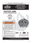
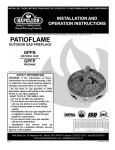
1
INSTALLER: THESE INSTRUCTIONS MUST BE CONVEYED TO AND REMAIN WITH THE HOMEOWNER.
CERTIFIED UNDER CANADIAN AND AMERICAN NATIONAL STANDARDS, CR97-003, CAN1-2.21-M85, IAS U.S. 4-96.
PATIOFLAME
INSTALLATION AND OPERATION INSTRUCTIONS FOR
OUTDOOR GAS FIREPLACE
GPFN
PROPANE GAS MODEL GPFP
NATURAL GAS MODEL
WARNING: If the information in these instructions is not followed exactly, a fire or
explosion may result causing property damage, personal injury or death.
FOR YOUR SAFETY
Do not store or use gasoline or other flammable vapours and liquids in the vicinity
of this or any other appliance.
WHAT TO DO IF YOU SMELL GAS:
• Do not try to light any appliance.
• Immediately call your gas supplier
• Do not touch any electrical switch.
from a neighbour's phone. Follow the
• Do not use any phone in your build
gas supplier's instructions.
ing.
• If you cannot reach your gas supplier,
call the fire department.
Installation and service must be performed by a qualified installer, service agency
or the gas supplier.
Wolf Steel Ltd., 24 Napoleon Rd., Barrie, ON L4M 4Y8 Canada • (705)721-1212 • fax(705)722-6031
www.napoleonfireplaces.com • [email protected]
W415-0372 / 02.12.03
2
WARNING
Impr
oper installa
tion, adjustment, alter
ation, ser
vice
Improper
installation,
altera
service
vice,, or maintenance can
cause injury or pr
oper
ty dama
ge. R
ead the installa
tion, oper
ating and mainteproper
operty
damag
Read
installation,
opera
nance instr
uctions thor
oughly bef
or
e installing or ser
vicing this equipment.
instructions
thoroughly
befor
ore
servicing
WARNING
DO NO
T LEA
VE P
ATIOFL
AME UN
ATTENDED WHEN IN USE.
PA
TIOFLAME
UNA
NOT
LEAVE
WARNING
FOR OUTDOOR USE ONL
Y.
ONLY
WARNING
DO NO
T USE FOR COOKING
NOT
COOKING..
TABLE of CONTENTS
PG 2-4
INTRODUCTION
Warranty
General Information
5
SPECIFICATIONS
Dimensions
Input
Gas Inlet Pressures
Minimum Clearance to Combustibles
6
INSTALLATION
Natural Gas
Propane
Enclosures for LP Gas Supply Systems
7
FINISHING
Log Placement
8
OPERATION
Operating Instructions
Maintenance
9
MAINTENANCE
High Elevation Installation
10-11 REPLACEMENTS
Ordering Replacement Parts
Replacement Parts
PLEASE RETAIN THIS MANUAL FOR FUTURE REFERENCE
W415-0372 / 02.12.03
3
NAPOLEON gas appliances are manufactured under the strict Standard of the world recognized
ISO 9001 : 2000 Quality Assurance Certificate.
NAPOLEON products are designed with superior components and materials, assembled by trained craftsmen who
take great pride in their work. The burner and valve assembly are leak and test-fired at a quality test station. Once
assembled the complete appliance is thoroughly inspected by a qualified technician before packaging to ensure that
you, the customer, receives the quality product that you expect from NAPOLEON.
NAPOLEON warrants its products against manufacturing defects to the original purchaser only -- i.e., the individual or legal entity (registered customer) whose name appears on the
W415-0372 / 02.12.03
4
GENERAL INFORMATION
WARNING
This appliance shall be used ONLY outdoors in a
well- ventilated space and shall NOT be used inside
a building, garage, or any other enclosed area.
WARNING
This appliance MUST NOT be used for cooking.
WARNING
THIS UNIT IS NOT FOR USE WITH SOLID FUEL.
WARNING
Cylinders must be stored outdoors in a wellventilated area out of reach of children. Disconnected cylinders must have threaded valve plugs
tightly installed and must not be stored in a
building, garage or any other enclosed area.
WARNING
Storage of this appliance indoors is permissible
only if it has been disconnected from its fuel
supply (natural gas line or LP gas cylinder).
The installation must conform with Local codes or in
the absence of local codes, with the National Fuel Gas
Code ANSI Z223.1/INFPA 54 in the United States or
CSA B149.1, Natural and Propane Installation code in
Canada.
The appliance and its individual shut off valve must be
disconnected from the gas supply piping system during
any pressure testing of the system at test pressures in
excess of 1/2 psig (3.5kPa).
This appliance must be isolated from the gas supply
piping system by closing its individual manual shut off
valve during any pressure testing of the gas supply piping system at test pressures equal to or less than 1/2
psig (3.5kPa).
The following clearances to combustible materials must
be maintained: Bottom - 0 inches, Sides (all around) 24 inches (610mm), Top - 6 feet (1.830m).
Always keep the appliance area clear and free from
combustible materials, gasoline, and other flammable
vapours and liquids.
Do not locate appliance where it can get excessively
wet. Do not use this appliance if any part has been
under water. Immediately call a qualified service technician to inspect the unit and to replace any part of the
control system and any gas control which has been
underwater.
W415-0372 / 02.12.03
• Installation and repair should be done by a qualified service person. The appliance should be inspected before use and at least annually by a qualified service person. More frequent cleaning may
equir
ed as necessary
ativ
e the conbe rrequir
tive
equired
necessary.. It is imper
impera
trol compartment, burners and circulating air passageways of the appliance be kept clean.
• IIff it is evident there is excessive abrasion or wear ,
or the hose is cut, it must be replaced prior to the
appliance being put into operation.
• Children and adults should be alerted to the hazards of high surface temperatures and should stay
away to avoid burns or clothing ignition.
•Y
oung c
vised
Young
childr
hildren
carefully
supervised
hildr
en should be car
efully super
when the
y ar
e in the ar
ea of the a
they
are
area
appliance
ppliance..
ppliance
• Clothing or other flammable materials should not
be hung from the appliance, or placed on or near
the a
ppliance
appliance
ppliance..
• Any guard or other protective device removed
for servicing the appliance must be replaced prior
to oper
ating the a
ppliance
opera
appliance
ppliance..
• Inspect the fuel supply connection for signs of
leakage (including the hose for LP models) before
eac
h use of the a
ppliance
each
appliance
ppliance..
• The pressure regulator and hose assembly supplied with LP models must be used. Replacement
pressure regulators and hose assemblies must be
those specified in this manual.
• The LP gas supply cylinder used with LP models
must be constructed and marked in accordance
with the specifications for LP-gas cylinders as requir
ed b
y the U
par
tment of T
ta
tion
quired
by
U.S
.S.. De
Depar
partment
Trranspor
ansporta
tation
.S
(DOT) or the Canadian Transport Commission
(CTC).
• The LP gas cylinder supply system must be arrang
ed ffor
apour withdr
aws
anged
va
withdra
ws..
or v
• The LP-gas cylinder used must include a collar
to pr
e.
protect
cylinder
valv
alve
otect the c
ylinder v
alv
• When an LP model is not in use, the LP-gas must
be turned of
ylinder
offf a
att the supply c
cylinder
ylinder..
•T
oe
xtend the lif
e of y
atiof
lame
To
extend
life
your
Pa
tioflame
lame,, pr
protect
our P
otect and
co
ver it fr
cov
from
use..
om the elements when not in use
5
SPECIFICATIONS
DIMENSIONS
INPUT
Model
Fuel
GPFN
GPFP
Natural Gas
Propane Gas
Max. Input
Btu/Hr
60,000
60,000
GAS INLET PRESSURES
Minimum Inlet Pressure
Maximum Inlet Pressure
Natural
4.5" w.c.
14.0"w.c
LP (Propane)
11.0" w.c.
14.0"w.c.
MINIMUM CLEARANCE TO COMBUSTIBLES
Floor
Side Walls
Top of unit to ceiling
Inches
0
24
72
mm
0
610
1830
W415-0372 / 02.12.03
6
INSTALLATION
The log set and the burner assembly are shipped together.
Remove the gas log set and burner assembly and check
for damage. DO NOT install damaged components. The
logs are fragile use care when handling.
Place the Patioflame on a level/secure surface in desired
location. This location must be adjacent to the gas supply
cylinder.
NOTE:Minimum clearances to combustible construction
must be maintained. ( See Page 5)
You must have clear and easy access to the on/off valve
AFTER the appliance is installed and connected to the gas
supply in order to safely turn off the burner.
THE ON/OFF G
AS V
AL
VE IS USED T
O TURN THE
GAS
VAL
ALVE
TO
BURNER ON AND OFF
OFF..
NATURAL GAS
Connect the incoming gas supply line to the on/off gas
valve of the appliance. Make certain ALL gas connections
are tight, turn the on/off valve at the unit slowly to the on
position and use soap water to test for leaks.
DO NOT USE AN OPEN FLAME.
LP GAS
1. Place the cylinder in the ring on the base. Base should
be on level surface.
2. Make sure tank valve is in its full off position. (Turn clockwise to stop).
3. Check tank valve features to ensure it has proper external mating threads. (Tank Valve Marked: USE WITH TYPE
1)
4. Inspect hose shipped with the unit for damage. Never
attempt to use damaged or plugged equipment. See your
local LP Gas Dealer for repairs.
5. After inspecting the LP hose shipped with the unit, connect the end with the female fitting on the hose to the male
fitting on the on/off gas valve at the end of the flex tube.
Tighten fittings using 2 wrenches.
6. When connecting regulator assembly to the tank valve,
hand tighten black QCC1 nut clockwise to a positive stop.
DO NOT use a wrench to tighten. Use of a wrench may
damage the quick closing coupling nut and result in a hazardous condition.
7. Locate the hose out of pathways where people may trip
over it or in areas where the hose may be subject to accidental damage.
8. Open tank valve fully (counter-clockwise). Turn the on/off
valve at the unit slowly to the on position and use a soapy
water solution to check all connections for leaks before
attempting to light the appliance. If a leak is found, turn
tank valve off and do not use the appliance until repairs
can be made.
W415-0372 / 02.12.03
ENCLOSURES FOR LP GAS SUPPLY SYSTEMS
If you build an enclosure for an LP gas cylinder, follow
these recommended specifications. You must also follow
local codes.
Enclosures for LP gas supply cylinders shall be ventilated
by openings at the level of the cylinder valve and at floor
level. The effectiveness of the opening(s) for purposes of
ventilation shall be determined with the LP gas supply
cylinder(s) in place. This shall be accomplished by one of
the following:
1. One side of the enclosure shall be completely open;
or
2. For an enclosure having four sides, a top and bottom:
a) At least two ventilation openings at cylinder valve level
shall be provided in the side wall, equally sized, spaced at
180 degrees (3.14 rad), and unobstructed. Each opening
shall have a total free area of not less than ½ square inch
per pound (3.2 sq. cm/kg) of stored fuel capacity and not
less than a total free area of 10 square inches (64.5 sq. cm).
b) Ventilation opening(s) shall be provided at floor level
and shall have a total free area of not less than ½ inch per
pound (3.2 sq. cm/kg) of stored fuel capacity and not less
than a total free area of 10 square inches (64.5 sq. cm). If
ventilation openings at floor level are in a side wall, there
shall be at least two openings. The bottom of the openings
shall be at floor level and the upper edge no more than 5
inches (127mm) above the floor. The openings shall be
equally sized, spaced at 180 degrees (3.14 rad) and unobstructed.
c) Every opening shall have minimum dimensions so as
to permit the entrance of a 1/8 inch (3.2mm) diameter rod.
3. Cylinder valves shall be readily accessible for hand operation. A door on the enclosure to gain access to the cylinder valve is acceptable, provided it is non-locking and can
be opened without the use of tools.
4. There shall be a minimum clearance of 2 inches
(50.8mm) between the lower surface of the floor of the LP
gas supply cylinder enclosure and the ground.
5. The design of the enclosure shall be such that (1) the LP
gas supply cylinder(s) can be connected, disconnected
and the connections inspected and tested outside the cylinder enclosure; and (2) those connections which could
be disturbed when installing the cylinder(s) in the enclosure can be leak tested inside the enclosure.
6. Be certain to mount or set the LP gas cylinder on a flat
surface and restrain it to prevent it from tipping.
Purge the gas supply line of any trapped air prior to the first
firing of the unit.
WARNING: During the initial purging and subsequent
lightings, NEVER allow gas valve to remain in the "Open"
position without first placing and igniting the firestarter.
8
OPERATION
Upon completing the gas line connection, a small amount
of air will be in the lines. When first lighting the burner, it will
take a few seconds for the lines to purge themselves of
this air.
Once the purging is complete, the burner will light and
operate as indicated in the instruction manual. Subsequent
lighting of the appliance will not require such purging unless the gas supply has been disconnected.
WARNING: Read and follow the safety and lighting instructions page in this manual and on labels on the appliance. IF
YOU DO NOT FOLLOW THESE INSTRUCTIONS PRECISELY, A FIRE OR EXPLOSION MAY RESULT AND YOU MAY BE
SERIOUSLY INJURED.
FOR YOUR SAFETY READ BEFORE LIGHTING:
A. This appliance must be lit by hand while following
these instructions exactly.
B. Before operating smell all around the appliance area
for gas and next to the floor because some gas is
heavier than air and will settle on the floor
C. Use only your hand to turn the manual gas control
valve. Never use tools. If the valve will not turn by hand,
do not try to repair it. Call a qualified service technician.
Force or attempted repair may result in a fire or explosion.
D. Do not use this appliance if any part has been under
water. Immediately call a qualified service technician to
inspect the appliance and replace any part of the control
system and any gas control which has been under water.
WHAT TO DO IF YOU SMELL GAS
• Do not try to light any appliance.
• Do not touch any electric switch; do
not use any phone in your building.
• Immediately call your gas supplier from a neighbour's
phone. Follow the gas supplier's instructions.
• If you cannot reach your gas supplier, call the fire department.
LIGHTING INSTRUCTIONS
1.
2.
Locate the manual gas control valve.
Place the firestarter near the burner ports on top of
the burner. Light the firestarter. For a Natural Gas
unit, turn on the ON/OFF valve slowly at the unit. For
a LP unit, turn the valve in the LP tank counter clockwise all the way and then turn on the ON/OFF valve
slowly at the unit.
3.
4.
If the burner does not light before the match goes out,
immediately turn the gas off.
Wait at least five (5) minutes to clear out any gas.
Then smell for gas including near the base of the
unit. If you smell gas, STOP! Refer to the safety information in the owner's manual. If you don't smell gas,
repeat step 2.
TO TURN OFF GAS
Turn the ON/OFF valve to the off position at the unit for
Natural Gas unit.
NOTE
The propane regulator in this appliance is equipped
with a low flow protection device. Unless the propane
cylinder valve is opened before the patioflame valve,
the gas flow will be reduced resulting in a very small
flame.
To reset this device, shut off the patioflame valve, then
the propane cylinder valve.
Next, disconnect the regulator adaptor from the tank
and then reconnect. Follow the lighting procedure ensuring the propane cylinder valve is opened before the
unit is.
W415-0372 / 02.12.03
For LP unit, turn the ON/OFF valve to the off position at the
unit and then turn the valve on the LP tank to the OFF
position clockwise.
9
MAINTENANCE
1. The appliance should be inspected before initial use
and inspected and cleaned at least annually by a qualified
field service person.
2. Tampering is DANGEROUS and voids all warranties.
Any component that is found to be faulty, must be replaced
with an approved component.
3. To obtain proper operation, it is imperative that the burner
flame characteristics are steady, not lifting or floating. Check
the burner flame patterns with the figure below.
During the winter months in cold weather climates, it is
recommended to disconnect the Patioflame and store it in
a cool dry place. Do not store the propane tank inside. For
the remainder of the year, protect and cover your Patioflame
from rain, freezing rain and snow.
HIGH ELEVATION INSTALLATION
This listed gas appliance is tested and approved for elevations from 0 to 4500 feet in Canada and the U.S.
When installing this appliance at an elevation above 4500
feet (in the U.S.), it may be necessary to decrease the input
rating by changing the existing burner orifice to a smaller
size. Input should be reduced four percent (4%) for each
1,000 feet above sea level, unless the heating value of the
gas has been reduced, in which case this general rule will
not apply. To identify the proper orifice size, check with the
local gas utility.
When installing this unit at an elevation above 4,500 feet
(in Canada), check with local authorities.
Consult your local gas utility for assistance in determining
the proper orifice for your location.
4. Periodically remove the logs and examine the burner. If
dirty, clean with a soft brush. Also examine the area around
the burner air shutter. Any dirt or foreign material, such as
spider webs or nests, in this area should be removed.
This will ensure long life and trouble free operation. When
the appliance is put back in service, check the burner flame
patterns with the figure above. Reinstall the logs as shown
in the log placement instructions.
5. Periodically check the hose connecting the LP gas cylinder to ensure it is not damaged in any way.
NOTE: Carbon (soot) may build up on the surface of the
logs with heavy use. This is more likely to occur when using LP gas. The soot should be cleaned off the surface of
the logs periodically to prevent excessive build up. To clean
the logs, be sure the fire is out, the gas supply is turned off
and the logs are cool to the touch. The soot can then be
brushed off with a dry bristle brush or cloth. Take care while
cleaning the logs as they can become damaged if mishandled. Care should be taken to dispose of the soot and
cleaning materials properly. Keep away from clothing and
outdoor furniture.
W415-0372 / 02.12.03
10
REPLACEMENTS
Contact your Napoleon dealer or the factory for questions
concerning prices and policies on replacement parts. Normally all parts can be ordered through your Napoleon dealer
or distributor.
When ordering replacement parts always give the following information:
FOR WARRANTY REPL
ACEMENT PAR
TS, A PHO
TOCOPY OF THE
REPLA
ARTS
PHOT
ORIGINAL INVOICE WILL BE REQUIRED TO HONOUR THE CLAIM.
1.
2.
3.
4.
5.
MODEL & SERIAL NUMBER OF APPLIANCE
INSTALLATION DATE OF APPLIANCE
PART NUMBER
DESCRIPTION OF PART
FINISH
* IDENTIFIES ITEMS WHICH ARE NOT ILLUSTRATED. FOR
FURTHER INFORMATION, CONTACT YOUR NAPOLEON
DEALER.
REPLACEMENT PARTS
1
2
3
8
9
9
10
11
12
13
14
15
16*
17*
18
19
20
21
W035-0104
W655-0176
W010-1030
W080-0618
W455-0076
W455-0077
GL-640
W135-0189
W135-0190
W135-0191
W135-0192
W135-0193
W550-0004
W550-0004
W175-0210
W530-0023
W655-0171
W530-0024
W415-0372 / 02.12.03
OUTER BASE
LOG SUPPORT
BURNER ASSEMBLY
ORIFICE BRACKET
PROPANE ORIFICE - #43
NATURAL GAS ORIFICE - #25
LOG SET
BASE LOG
LOG #1
LOG #2
LOG #3
LOG #4
AGGREGATE SHALE
AGGREGATE LAVA ROCK
FLEX c/w SHUT OFF - stainless steel
PROPANE REGULATOR / HOSE ASSEMBLY (LP UNITS ONLY)
BASE (LP UNITS ONLY)
NG REGULATOR (NG UNITS ONLY)
11
W415-0372 / 02.12.03
12
W415-0372 / 02.12.03
Wolf Steel Appliance Service History
This appliance must be serviced annually depending on usage.
Date
Dealer Name
Service Technician
Name
Service Performed
Special Concerns