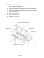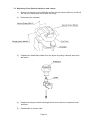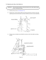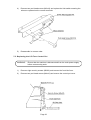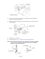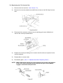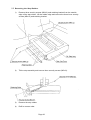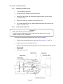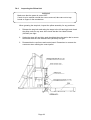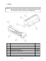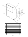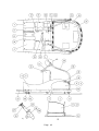
1
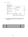
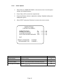
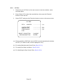
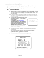
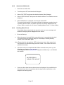
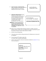
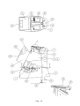
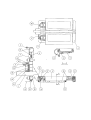
52"
Operators Manual
IT IS THE RESPONSIBILITY OF THE OPERATOR TO MAINTAIN CUSTOMER SAFETY AT
ALL TIMES, AND IT IS IMPERATIVE THAT THE DETAILS SET OUT IN THIS MANUAL
ARE FOLLOWED PRECISELY,
Part No. 90500085
© 1994 NAMCO LIMITED all rights reserved.
No part of this publication may be reproduced by any mechanical, photographic or electronic
process, or in the form of phonographic recording, nor may it be stored in a retrieval system,
transmitted or otherwise copied for public or private use, without permission from
NAMCO EUROPE LIMITED
While the information contained in this manual is given in good faith and was accurate at the
time of publication, NAMCO EUROPE LTD. reserve the right to make changes and alterations
without notice.
This machine has been manufactured in accordance with European Community directives
marking. Any changes or modifications to this
(1st. January 1996), and as such bears the
machine must be in accordance with European Community directives (1st. January 1996).
If you make any unauthorised changes to this product, you may contravene European
Community directives (1st. January 1996)
Published by:
NAMCO EUROPE LIMITED
Namco House,
8 Acton Park Estate,
The Vale,
London. W3 7QE
Phone:- 0208-324-6000
Fax:- 0208-324-6010
SAFETY WARNING
In order to use this machine safely, be sure to read this Operators Manual carefully
before installation, adjustment or use of this machine.
Whenever the owner of this machine entrusts disassembly, installation, adjustment,
routine maintenance or trouble shooting to another person, the owner should ensure
that that person read the appropriate precautions and relevant sections of this manual
before starting work.
In order that no accidents occur when the machine is in operation, strictly
follow the notes on safety described below. Also, carefully read section 2,
"Precautions"
Warnings for Operation (
NOTE:
NOTE:
NOTE:
NOTE:
Requirements)
Only operate this machine after checking that it has been installed correctly
and in accordance with the installation and commisioning manual.
Parts of this machine move during game play, so there are places where the
distance between the stationary section and moveable section changes.
There are warning notices to keep hands and feet clear of moving parts,
however if the operator feels that a person is in any danger, he should warn
that person accordingly.
The warning notices must always be kept in good condition and replaced if
worn, so that the customer can read it clearly.
If there is an error or problem with this machine, operation must be
stopped immediately and the problem rectified before further use.
Warnings for Disassembly, Installation, Routine Maintenance, and Troubleshooting.
DANGER:
DANGER:
DANGER:
DANGER:
NOTE:
Namco Ltd. bears absolutely no responsibility for accidents or injuries
resulting from unauthorized changes to this machine.
Ensure that the machine has been turned OFF before making adjustments
or carrying out maintenance. Also ensure only qualified personnel carry
out maintenance or turn the power ON to this machine.
The power supply and inside the monitor will remain hot and have areas of
high voltage even though the machine has been turned OFF, and there is
a possibility of burns or electric shock. Be careful not to touch these areas.
In order to avoid injuries due to mis-operation, be sure that the voltage of
the main power supply is within the prescribed limits. Also to prevent
possible electric shocks due to failure, this machine MUST be fitted with a
securely connected earthed plug.
Do not turn the power switch ON until the machine has been installed
correctly.
1. SPECIFICATIONS
POWER SUPPLY :-
230volts AC
MONITOR :-
Thomson 52" Projector Monitor (RP52)
COIN ACCEPTOR
Mars CashFlow - 1 Channel
DIMENSIONS :Assembled
Monitor Cabinet
Ski Assembly
Header
1265(w)
1250(w)
1265(w)
1145(w)
x
x
x
x
2245(d)
645(d)
1600(d)
350(d)
x
x
x
x
2320(h)
1940(h)
1220(h)
380(h)
WEIGHT :Assembled
Monitor Cabinet
Ski Assembly
Header
ACCESSORIES :-
458kg
200kg
240kg
18kg
Keys:
(Cash Door) ............................ 2
(Coin Door) ............................. 2
(Service Door) ......................... 2
IEC Mains Lead ............................................ 1
Operators Manual ......................................... 1
Installation Manual ....................................... 1
Monitor Manual ............................................. 1
Monitor Remote Control W/Batteries ........... 1
Cashflow Data .............................................. 1
Floor Safety Mat & Decal ............................. 1
Floor Safety Mat Securing Plate .................. 2
Floor Safety Mat Support Bracket ................ 2
Joint Bracket - LHS ...................................... 1
Joint Bracket - RHS ...................................... 1
Potentiometer ............................................... 1
M10x35 Hex Head Set Screw - S/Steel ....... 8
M10 Flat Washer - S/Steel ........................... 8
M10 Spring Washer - S/Steel....................... 8
M8x20 Hex Head Set Screw - S/Steel ......... 4
M8 Flat Washer - S/Steel ............................. 4
M8 Spring Washer - S/Steel ......................... 4
M6 Dome Head Nut - Chrome ..................... 6
M6X25 Hex Head Screw - BZP .................... 2
M6 Flat Washer H/Duty - BZP ...................... 2
M6 Spring Washer - BZP ............................. 2
M4 Security Wrench ..................................... 1
M5 Security Wrench ..................................... 1
M6 Security Wrench ..................................... 1
Page 6
2. PRECAUTIONS
Be sure to read this section carefully.
2-1 Notes on Operation (
NOTE:
NOTE:
NOTE:
NOTE:
NOTE:
NOTE:
NOTE:
Requirements)
Only operate this machine after checking that it has been installed correctly
and in accordance with the Installation and Commisioning Manual.
Parts of this machine move during game play, so there are places where the
distance between the stationary section and moveable section changes.
There is a warning sticker that the player must be wearing flat shoes,
unsuitable footwear e.g. high heel shoes could cause the player to lose
balance and fall. However if the operator feels that a customer playing the
game is in any danger, he should warn the customer accordingly.
The warning sticker must always be kept in good condition so that the
customer can read it clearly, and be replaced if worn.
Ensure customer safety at all times. Be especially careful in the case of
young children, who should be supervised by an adult at all times.
If there is an error or problem with this machine, operation must be
stopped immediately.
Service, adustments and routine maintenance should be carried out by
qualified personel only.
Parts of this machine swing to the left and right during game play. In order to
maintain the customer's safety, the operator should strictly follow the
appropriate precautions.
2-2 Safety Mechanisms and Controls
For safety, this machine is equipped with a locking mechanism for securing the steps
when the machine is not being played.
•
The step locking mechanism is controlled as describe below.
a.
After selecting the course, the step lock is released before game start.
b.
At game over, the steps are locked.
c.
If the steps are moved left or right while they are locking or unlocking, the motor
temporarily stops in order to prevent damage to the step-lock motor. When the
steps are no longer being moved left or right, the motor will restart. To prevent
damage from occurring, do not move the steps while the motor is running.
d.
When the machine is first turned ON, the step-lock mechanism is checked
automatically by unlocking and re-locking the steps.
e.
If the step-locking system fails, an error message will be displayed on the monitor
screen.
Refer to section 6-4-3 "Handling Motor Errors" and section 8 "Trouble Shooting".
Page 7
2-3 Cautions When Transporting.
a.
Do not subject the game to physical shock when transporting or moving it.
b.
Always return the levellers to the UP position before moving the machine, even
for short distances.
c.
The monitor cabinet, ski assy and header assy must be separated before
shipping.
d.
Take care not to rope any moulded (plastic) parts when transporting.
e.
Always ship the monitor section upright.
THIS MACHINE IS NOT DESIGNED TO BE MOVED BY FORK LIFT. DO NOT USE
Page 8
2-4 Cautions When Installing.
1.
This machine is designed for indoor use only. Do Not install the machine in the
following places
2.
If this machine is installed next to walls or other machines, ensure that there is
plenty of space between them.
Page 9
NOTE: So that customers are not injured by the movement of the Ski Tray, ensure that
there is at least 300mm separation between other machines or walls.
If two Alpine Racer machines are next to each other the space between them
must be at least 600mm.
NOTE: In order to gain access to the Power Supply and CPU assemblies, make sure that
the rear of the machine is separated from a wall or other machine by at least
500mm.
Page 10
3. HOW TO PLAY
This game is based on Alpine ski racing.
The player stands on the steps and moves them left or right to control the skier.
By using the inner edge when moving the steps, the skier slows down and turns
quickly.
•
Race Mode
The player races the computer skiers and the object is to cross the goal line first.
The game is over when the player crosses the finish line within the given time
period, or the time period reaches zero. The time period is increased each time a
player passes a check point.
If a player wins in a fast time they can enter their initials. Select letters using the
select buttons and enter them by using the decision (Viewpoint) button.
•
Time-Trial Mode
The object of the game is to pass between the flags (gates) and to cross the
finish line in the fastest time. The rules require the player to go through the gates,
so more technique is needed for this mode than the normal race mode.
The game is over when the player crosses the finish line within the given time
period, or the time period reaches zero. The time period is increased by one
second each time a player passes through a gate.
If a player completes a course in a fast time they can enter their initials. Select
letters using the select buttons and enter them by using the decision (Viewpoint)
button.
A player is not disqualified for not passing through a gate, however the player will
not be able to enter their initials even if they cross the finish line in a good time.
•
Game Mode Selection
After inserting sufficient credit, the "Game Mode Selection" screen is displayed.
The player selects either the "Race Mode" or "Time-Trial Mode" by using the L/R
selection buttons, and pressing the decision (Viewpoint) button.
•
Course Selection
After the game mode has been selected, the "Course Selection" screen is
displayed.
The player can select one of three courses, "Novice", "Intermediate" and
"Expert".
•
Viewpoint Selection
The viewpoint button can pressed at any time during a game to switch between
the player's view and behind view.
Players View: This is the view as seen by the skier. This provides an exciting
view while skiing. The race mode starts in this view.
Behind View: This is the view from behind the skier. This view can be used to
get an understanding of the skiers posture and surrounding
conditions. The time trial mode starts in this position.
Page 11
4. MAJOR COMPONENTS
Page 12
5. INSTALLATION
WARNING If the location site of this machine has a polished floor it is recommended
that rubber pads are fitted under the level adjusters to prevent the
machine sliding on the floor.
5-1 Fitting the Header Assembly
The Header Assembly has a forward centre of gravity, so it is important that
at least two people are used to fit or remove the Header Assembly.
The fitting position of the Header Assembly is very high, and it is important
that a means of reaching the height safely, without stretching, is available.
(e.g. steps, step stools etc.)
1.
Place the Header Assembly on to the monitor cabinet, connect the connectors
and pass the connectors in to the cabinet, slide the header back ensuring that
it engages fully in to the retaining brackets at the front of the monitor cabinet.
2.
Fit the 2off M6x25 Hex Head Screws, Spring and Flat washers to retain the
Header Assembly to the cabinet.
Page 13
5-2 Connecting the Ski Assy to the Monitor Cabinet.
1.
Connect the connectors between the Ski Assembly and Monitor Cabinet.
2.
Push the Ski Assembly fully up to the monitor cabinet, taking care not to trap
any wires.
3.
Fit, finger tight, a joint bracket to each side using 4off Hex Head Set Screws
(M10x25), Spring and Flat Washers on each bracket. Tighten fully all screws.
(Note: Joint Brackets are handed, ensure bracket is fitted with fixing holes
uppermost.)
Page 14
NOTE:When the machine is fully assembled and in its final position, lower the 10 level
adjusters, (4 on the monitor cabinet and 6 on the ski assy), with a spanner so that
all castors are raised from the floor by approximately 5mm, and the machine is
level. Tighten the lock nuts with a spanner to ensure that the level adjusters do not
move.
If this machine is installed on a smooth or shiny floor, it is recommended that rubber
slip mats be placed under each adjustable foot to prevent the machine from moving
when being played.
5-3 Fitting the Safety Mat
1.
Assemble the Floor Safety Mat by fitting the securing plates from underneath,
the support brackets from the top and retaining the assembly together with
the M6 Dome Nuts.
2.
Place the assembled Safety Mat into position under the Ski Step Assy.
3.
Retain the Safety Mat in position with the Hex Head Set Screws (M8x20), Spring
Washers and Flat Washers
Page 15
6. ADJUSTMENTS
6-1 Turning on the Power
After the machine has been installed, turn ON the power. The power switch is
located on the rear of the monitor cabinet.
6-2 Adjustment Switches
The Adjustment switches are located inside the coin door.
1.
Service Switch.
Press this switch to obtain game credits without incrementing the play meter.
2.
Test Switch
Slide the test switch ON to enter test mode.
Test mode allows testing and the changing of game settings. (Refer to section
6-3 "Test Mode" (page 12))
COIN COUNTER
LEFT PLAYER
TEST
RIGHT PLAYER
SERVICE
TEST
Service Bracket
Page 16
SERVICE
6-3 Test Mode
1.
Open the coin door and slide the test switch "ON". The menu screen will be
displayed on the monitor.
2.
Select the test required by pressing the 'Left or Right Selection' push button. The
selected test will 'blink'.
3.
Enter the selected test by pressing the 'Decision' push button. Select "EXIT" to
return the "Menu Screen".
4.
After testing is completed, ensure that the test switch is returned to the "OFF"
position to return to normal game mode.
The Test Switch must always be in the "OFF" position for normal game mode.
MENU
COIN OPTIONS
-----------------
(1) Sets the price of play (See 6-3-1)
GAME OPTIONS
-----------------
(2) Sets the game options (See 6-3-2)
I/O TEST
---------------------------------
(3) Used for testing switches and controls
(See 6-3-3)
SOUND TEST
---------------------------------
(4) Used for testing sound and setting
volumes (See 6-3-4)
MONITOR TEST
-----------------
(5) Used for adjusting the monitor
ADS TEST
-----------------
(6) Displays accumulated game data
OTHERS
---------------------------------
(7) Used for testing the PC Boards and for
initializing all of the settings
L/R SELECTION BUTTON : CHOOSE
DECISION BUTTON : ENTER
Decision Button
Select L/R Buttons
Page 17
6-3-1
Coin Options
1.
2.
3.
4.
Select item (1) "COIN
OPTIONS" on the
menu screen to set
the game cost and
related settings.
Press 'Select L/R' to
select the required
item.
COIN OPTIONS
[ DEFAULT IN GREEN ]
GAME COST
1 COIN 1 CREDIT
FREE PLAY OFF
Use the 'Decision'
button to adjust the
settings.
Select "EXIT" to
return to the menu
screen.
------------------------ (a)
------------------------ (b)
EXIT
SELECT L/R BUTTON
DECISION BUTTON
: CHOOSE
: CHANGE +
Note :- The price of play on this machine is set within the Cashflow Coin Mech.
Ensure that the Coin Options on the screen are set as shown in the
following table.
ITEM
CONTENTS
FACTORY SET
(a) Game Cost No of Coins required for No. of credits - - - - - - settable 1 - 9 1 Coin 1 Credit
(b) Free Play
Yes/No
NO
Page 18
6-3-2
Game Options
1.
Select item (2) "GAME OPTIONS" on the menu screen to set the game
options and related settings.
2.
Press 'Select L/R' to select the required item.
3.
Press the 'Decision' button to adjust the settings. Standard settings are
displayed in green.
4.
Select "EXIT" and press 'Decision' to return to the menu screen.
GAME OPTIONS
[ DEFAULT IN GREEN ]
GAME DIFFICULTY
SOUND IN ATTRACT
HI SCORE INITIALIZE
AUTO HIGH SCORE INITIALIZE
B
ON
NO
OFF
------------ (a)
------------ (b)
------------ (c)
------------ (d)
EXIT
SELECT L/R BUTTON : CHOOSE
DECISION BUTTON : CHANGE +
ITEM
DESCRIPTION
(a) Game Difficulty
A (easy) to C (hard)
(b) Sound in Attract
On / Off
(c) Hi Score Initialize
Yes / No
(d) Auto High Score Initialize Yes / No
FACTORY SET
B
On
(If Yes Hi Score will be reset when exiting test)
No
(If Yes Hi Score will be reset every time the machine is
switched OFF)
Off
Page 19
6-3-3
I/O Test
1.
Select item (3) "I/O Test" on the menu screen to test the switches, motor
and step adjust.
2.
Press 'Select L/R' to select the required item, then press the 'Decision'
button to enter the test.
3.
Select "EXIT" and press the 'Decision' button to return to the menu screen.
I/O TEST
DIP 4
12345678
............................(a)
SWITCH TEST
MOTOR TEST
STEP ADJUST
EXIT
SELECT L/R BUTTON
DECISION BUTTON
............................(b)
............................(c)
............................(d)
:
:
CHOOSE
ENTER
(a) Shows condition of DIP SW 4 on the PCB. In normal operation all switches
are OFF. (If a switch is ON, it will be displayed in red.)
(b) For testing Switches and Control Pots. (See 6-3-3-1 )
(c) For testing the Step-Lock Motor. (See 6-3-3-2)
(d) For initializing the Step Control Pots. (See 6-3-3-3)
Page 20
6-3-3-1
1.
Switch Test
Select Switch Test from the 'I/O Test' menu. The following screen will
appear on the monitor.
Note:- On entering Switch Test the Skis will be unlocked. Ensure that the
Skis are returned to the locked condition at the end of the test by
entering Motor Test (See 6-3-3-2)
SWITCH TEST
TEST SW
ON
.................(a)
COIN SW
ON
.................(b)
SERVICE SW ON
.................(c)
R SELECTION BUTTON
ON ............(d)
DECISION BUTTON
ON ............(e)
L SELECTION BUTTON
ON ............(f)
SWING 0000 0000 CENTER .........(g)
EDGE
0000 0000 CENTER .........(h)
L/R SELECT + DECISION
2.
: EXIT
The word 'ON' will appear next to items (a) to (f) each time the
respective switch is operated.
When the skis are pushed left, 'SWING-CENTRE' will change to 'LEFT'
and 'OK' will appear just before it reaches the extreme left,. When the
skis are pushed right, 'CENTRE' will change to 'RIGHT' and 'OK' will
appear just before it reaches the extreme right. '0000' will increase
when the skis are moved to the right and decrease when they are
moved to the left.
When the skis are tilted, 'EDGE-CENTRE' will change to 'LEFT or
RIGHT' and 'OK' will appear just before they are fully tilted. '0000' will
change as the skis are tilted.
Note: "EDGE" 'OK' will only appear if you stand and
apply weight to the edges of the ski steps.
There is no problem if 'OK' is not displayed
when standing on the steps in the same way
as normal play.
3.
If 'OK' is not displayed when the edge is tilted left or right, re-initialize as
described in section 6-4 "Initialization After Replacing Parts".
4.
Operate both of the 'Select L/R' buttons and 'Decision' button together
to exit and return to the 'I/O Test' menu screen.
Page 21
6-3-3-2
1.
Motor Test
Select Motor Test from the 'I/O Test' menu. The following screen will
appear on the monitor.
MOTOR TEST
NOW MOTOR STATE
GO MOTOR
: FREE
: LOCK ............(a)
.................(b)
EXIT
L/R SELECT BUTTON
DECISION BUTTON
: CHOOSE
: EXIT
(a)
Displays the current condition of the Skis.
Display will show 'LOCK - FREEING - FREE - LOCKING' as the Skis
are tested.
(b)
Allows the Skis to be locked and unlocked.
Display will show 'FREE - NOW MOVING - LOCK' as the Skis are
being tested.
Note:- Ensure Skis are in the locked condition before returning to normal
game mode.
6-3-3-3
1.
Step Adjust
Select Step Adjust from the 'I/O Test' menu.
On entering 'STEP ADJUST' test, Step Adjust on the 'I/O' Menu Screen
will blink and 'INITIALIZE COMPLETED' will appear and be blinking.
Ski Step initialization is now completed.
2.
Select EXIT to return to the Main Menu Screen.
Page 22
6-3-4
Sound Test
1.
Select item (4) "Sound Test" on the menu screen to test the sound and speakers.
2.
The following screen will appear on the monitor.
SOUND TEST
VOLUME LEFT SP.
RIGHT SP.
REQUEST SONG No.
1F
------------------- (a)
1F
------------------- (b)
00
------------------- (c)
EXIT
L/R SELECT BUTTON : CHOOSE
DECISION BUTTON : ENTER
3.
Select the required item by 'Select L/R' buttons. The selected item will ‘blink’.
4.
Pressing the Decision button will cause the selected value setting to blink.
5.
Pressing 'Select R' will increase the value and 'Select L' will decrease the value.
6.
Press ‘Decision’ button to return to item select mode.
7.
When selecting the 'Request Song No.' test, 'Select R' button will increase the
song number and 'Select L' will decrease the number. The 'Decision' button will
produce the sound of the song number selected. (Request Song 01 will produce
a stereo sound test. Sound will be produced from the speakers in the following
order:- Left speaker, Right speaker, Both speakers)
8.
Press both Select L/R buttons and Decision button together to return to Sound
Test Menu from Request Song No. Test
Item
Description
Factory Set
a
Set left speaker volume
------
00 Quietest - 3F Loudest
3A
b
Set right speaker volume
------
00 Quietest - 3F Loudest
3A
c
Select sound for testing. Each number will produce a different sound. 01 will
generate a stereo test.
Page 23
---
6-3-5
Monitor Test
1.
Select item (5) “Monitor Test” on the menu screen to set up and adjust the
monitor.
2.
On entering monitor test, the screen will display one of the following test
patterns.
GRADATION PATTERN
CROSSHATCH
CROSSHATCH
WHITE WINDOW
WHITE WINDOW
WHITE WINDOW
INTERLACE PATTERN
VIEW ANGLE ADJUST
VIEW ANGLE ADJUST
FULL WHITE
GREEN
WHITE
(H)
(M)
(L)
(CRT)
(PROJECTOR)
3.
Use 'Select L/R' buttons to change to the next pattern and 'Decision' button
to return to the Main Menu.
4.
Refer to monitor manual for monitor adjustments.
6-3-6
ADS Data
1.
Select item (6) "ADS Data" on the menu screen to view machine history
details.
2.
The following screen will appear on the monitor.
ADS
PLAY
GOAL
EXT0
EXT1
EXT2
GATE
RACE
NOV
0000
0000
0000
0000
0000
----
RACE
T.T.
NOV
000'00"00
000'00"00
INT
0000
0000
0000
0000
0000
----
EXP
0000
0000
0000
0000
0000
----
:
:
INT
0000
0000
---------0000
INT
000'00"00
000'00"00
PLAY TIME
000' 00" 00
PLAY NUMBER
0000
L/R SELECT
DECISION
T.T.
NOV
0000
0000
---------0000
EXP
0000
0000
---------0000
.................. (a)
.................. (b)
.................. (c)
.................. (d)
.................. (e)
.................. (f)
EXP
000'00"00
000'00"00
............... (g)
............... (h)
....................................... (i)
....................................... (j)
INITIALIZE ............................. (k)
EXIT
CHOOSE
ENTER
Page 24
Item
Description
(a) Play
Total number of games played at each difficulty level for each course.
(b) Goal
Total number of games completed at each difficulty level for each
course.
(c) Ext0
Number of games finishing at 1st extended time gate at each difficulty
level in race game.
(d) Ext1
Number of games finishing at 2nd extended time gate at each difficulty
level in race game.
(e) Ext2
Number of games finishing at 3rd extended time gate at each difficulty
level in race game.
(f) Gate
Total number of gates completed for each difficulty level in T.T. game.
(g) Race
Total time in Hrs, Mins, Secs each difficulty level has been played in
race game.
(h) T.T.
Total time in Hrs, Mins, Secs each difficulty level has been played in
T.T. game.
(i) Play Time
Total time in Hrs, Mins, Secs game has been played.
(j) Play Number
Total number of game plays.
(k) Initialize
Resets all ADS Data to zero.
6-3-7
Others
1.
Select item (7) "Others" on the menu screen.
2.
On entering 'Others' the following screen will appear on the monitor.
OTHERS
(DEFAULT IN GREEN)
BACK UP MEMORY INITIALIZE
NO
EXIT
L/R SELECTION BUTTON : CHOOSE
DECISION : CHANGE +
3.
Selecting Back Up Memory Initialize will return all adjustable settings to
factory preset.
Page 25
6-4 Initialization After Replacing Parts
Initialization must be performed after replacing the game PC board, Rom or Step
Controls. If initialization is not performed, the game will not function correctly.
During initialization, ensure that the step edges are level.
6-4-1
Adjustment Method (a)
1.
When the power is turned ON the step-lock motor is automatically checked.
The motor check first locks the steps (If not already locked), unlocks, then
locks them again.
Note: Ensure that the test switch is OFF during motor check. Also ensure that
the steps are not touched during the motor check, or the check will not be
performed correctly.
2.
If the first lock is not completed within fifteen
seconds from power up, an error display
screen appears.
If this happens, refer to section 6-4-2
"Adjustment Method (b)", and initialize the
controls. If the error display screen is still
showing after the controls have been
initialized, refer to section 6-4-3, "Handling
Motor Errors".
After the motor check is successful the
attract screen is displayed.
MOTOR ERROR 1
PLEASE STEP ADJUST
3.
To initialize the controls, Switch the test switch ON while pressing the
service button.
The screen displays the "SWITCH TEST" screen with INITIALIZE
COMPETED flashing, Initialization is completed.
4.
Turn the test switch OFF to return to normal game mode.
SWITCH TEST
TEST SW
ON
COIN SW
ON
SERVICE SW ON
R SELECTION BUTTON
On
DECISION BUTTON
ON
L SELECTION BUTTON
ON
SWING 0000 0000 CENTER
EDGE
0000 0000 CENTER
INITIALIZE COMPLETED
L/R SELECT + DECISION : EXIT
Page 26
6-4-2
Adjustment Method (b)
1.
Slide the test switch ON.
2.
Turn the power OFF and then back ON again.
3.
Select "I/'O TEST" and press the decision button (View Change).
4.
Select "STEP ADJUST" and press the decision button. The controls are now
initialized.
5.
After initialization is completed, turn the test switch OFF.
The motor check begins. If the motor still does not operate correctly, there is
a problem with the motor or switches, and an error will be displayed on the
screen. Refer to section 6-4-3, below, "Handling Motor Errors", for fault finding.
6-4-3
Handling Motor Errors
If a problem has occurred with the step-lock motor, an error message and
method of rectifying will be displayed on the screen.
1.
Errors at Start-up
a.
When the power is turned ON the step-lock motor is automatically checked.
The motor check first locks the steps (If not already in locked position),
unlocks, then locks them again.
Note: Ensure that the test switch is OFF during motor check. Also ensure that
the steps are not touched during the motor check, or the check will not be
performed correctly.
b.
If the first lock is not completed within fifteen seconds from power up, the
following error display screen appears.
If this happens, refer to section 6-4-1 "Adjustment Method (a)", and initialize
the controls.
MOTOR ERROR 1
PLEASE STEP ADJUST
c.
If an error other than the one shown above is displayed, it is possible that a
fuse has blown, there is a problem with the step-motor mechanism or the
steps are not moving freely.
Page 27
d.
e.
If the first lock is completed within
fifteen seconds, but the steps cannot be
released, Motor Error 2 screen is
displayed until the fault is rectified.
If after the steps have been freed,
they do not re-lock, as an
emergency measure, Motor Error 3
screen is displayed. This allows
the step-lock mechanism to be
overridden and the game to be
operated with the steps
permanently in the free position.
MOTOR ERROR 2
OPERATION STOP!!
MOTOR ERROR 3
DO YOU WANT TO OPERATE
YES>PUSH DECISION BUTTON
NO>PUSH L/R SELECT BUTTON
WARNING: It can be dangerous to
operate the machine with the
steps permanently free, so the
fault MUST be repaired as soon
as possible.
If the game is to be operated with the steps in the free condition, press the
decision button. If either the Left or Right Select button is pressed the game
will cease to function until the fault has been rectified.
2.
An Error Occurs During Play.
a.
If the motor stops function during game play, the following error screen will
be displayed.
b.
Turn the power OFF and then back ON.
The motor will be checked automatically.
c.
If there is still a problem, follow the instructions detailed in section 6-4-3 (1),
"Errors At Start-up".
WARNING!
STEP LOCK DEVICE IS OUT
OF ORDER
CALL THE ATTENDANT
IMMEDIATELY.
Page 28
7. MAINTENANCE
DANGER: In order to prevent injury or electric shock to service personnel, ensure that
the MAIN POWER IS OFF before attempting any maintenance.
DANGER: Before performing any work not described in this manual, be sure to contact
your distributor to receive instructions or answers to questions.
7-1 Care of the Projector Monitor
The projection tube lenses have been manufactured from plastic material.
Prevent contact with the lenses, because various lens faces have been
provided with a special coating which is easily damaged.
Only the side of the lens directed towards the mirror, the mirror and the
projection screen are allowed to be cleaned.
If cleaning is absolutely necessary, observe the following points :
•
Blow off dust, or remove with a dust brush or soft lint-free cloth.
•
If necessary, clean with a soft lint-free cloth, moistened with water to which a
little detergent has been added.
•
DO NOT USE organic solvents such as alcohol, dry cleaning naptha,
trichlorethylene, acetone, etc., these agents may cause permanent damage
to the plastic lenses or projection screen.
Page 29
7-2 Replacing the Fluorescent Tube
1)
Remove the ten socket button head screws (M5x12), and remove the side vacforms (five screws on each vac-form)
2)
Remove the two countersunk screws (M5x12) from the bottom of the acrylic.
3)
Remove the two socket button head screws (M4x25), and remove the header
acrylic retaining bracket.
4)
Remove the header acrylic.
5)
Replace the fluorescent tube.
6)
Reassemble in reverse order.
Page 30
7-3 Replacing Push Button Switches and Lamps
1)
Remove six security screws (M5x20) and two security screws (M5x12), and lift off
the top cover taking care not to strain the wiring.
2)
Disconnect the connector.
3)
Separate the switch/lamp holder from the button by pulling it directly away from
the button.
4)
Replace the lamp or switch ensuring that the correct wires are replaced on the
terminals.
5)
Reassemble in reverse order.
Page 31
7-4 Replacing the Step Limit Switches
WARNING:
Ensure that the machine is disconnected from the main power supply
before commencing work.
1)
Remove the top cover. (See Section 7-3)
2)
Remove four security screws (M5x12) securing each side vac-form to the mast
assembly and remove both side vac-forms and front vac-form as one assembly.
3)
Remove two pozi head screws (M4x10) and remove the limit switch mounting
bracket.
Page 32
4)
Remove two pozi head screws (M3x16) and replace the limit switch ensuring the
wires are replaced on the correct terminals.
5)
Reassemble in reverse order.
7-5 Replacing the L/R Turn Control Pot
WARNING:
Ensure that the machine is disconnected from the main power supply
before commencing work.
1)
Remove eight security screws (M5x20) and remove the front Vac-form.
2)
Remove two pozi head screws (M4x10) and remove the control pot cover.
Page 33
3)
Disconnect the connector, slacken the pot retaining grub screw (M4x8) and
remove the control pot and bracket.
4)
Replace the control pot taking care to ensure that the wires are replaced to the
correct terminals.
5)
Reassemble in reverse order.
6)
Re-initialize game. (See 7-7 "Adjustments When Replacing Parts")
NOTE: When refitting the control pot ensure that the pot locating tab engages
in the hole in the mounting bracket and that the grub screw (M4x8)
engages on the flat of the pot shaft.
Page 34
7-6 Replacing the Tilt Control Pot
1)
Remove the front vac-form. (See Section 7-3)
2)
Remove four security head screws (M5x12) and remove the Ski Step front vacform.
3)
Disconnect the connector, slacken the pot retaining grub screw (M4x8) and
remove the control pot and bracket.
4)
Replace the control pot taking care to ensure that the wires are replaced to the
correct terminals.
5)
Reassemble in reverse order.
6)
Re-initialize game. (See 7-7 "Adjustments When Replacing Parts")
NOTE: When refitting the control pot ensure that the pot locating tab engages
in the hole in the mounting bracket and that the grub screw (M4x8)
engages on the flat of the pot shaft.
Page 35
7-7 Removing the Step Rubber
1)
Remove three security screws (M5x12) and retaining bracket from the outside
edge of the step rubber, Lift the rubber edge and remove the three inner security
screws (M5x12) and retaining bracket.
2)
Tilt the step assembly and remove three security screws (M5x12).
3)
Remove the step rubber.
4)
Refit in reverse order.
Page 36
7-8 Step-Lock Maintenance
7-8-1
Releasing the Step-Lock
1.
Turn the power switch ON
2.
Press the service switch, and start the game.
3.
When the game starts, the restriction plate (see diag.) moves to the
released position.
4.
When the steps are released, turn the power OFF.
5.
To re-lock the steps turn the power ON and the steps will re-lock in the
power up motor check.
7-8-2
Greasing the Step-Lock
WARNING
Make sure that the power is turned OFF.
If work is to be carried out with the covers removed, take care not to trap
hands or fingers in the mechanism.
The step-lock should be greased every three to four months.
1.
Remove the control panel and vac-forms (See sections 7-3 and 7-4).
2.
Apply grease to the following locations.
•
•
•
•
Between the restriction plate and guide rails, and between the cam follower.
Screw shaft
Pillow shaft
Sub torsion bar axle
Page 37
7-8-3
Inspecting the Pillow Unit
WARNING
Make sure that the power is turned OFF.
If work is to be carried out with the covers removed, take care not to trap
hands or fingers in the mechanism.
When greasing the step-lock, inspect the pillow assembly for any problems.
1.
Release the step-lock and swing the steps to the left and right, and check
the pillow units for any wear. Also check that the Hex Head Screws
(M14x45) are tight.
2.
Swing the steps left and right, and check that the main torsion bar is secure.
Also check that the Hex Head Screws (M10x25) are tight.
3.
Reassemble the vac-forms and control panel. Remember to connect the
connector when refitting the control panel.
Page 38
8. TROUBLE SHOOTING
•
Ensure that the power is turned OFF before making adjustments or replacing
parts.
•
If none of the items below correspond to your problem, or if the problem is not
corrected by the treatment described below, contact your dealer for further
advice.
•
Always return PC Boards to your dealer for repair. Never test the PC board for
continuity with a multimeter or similar device. The PC Board contains sensitive
devices which could be damaged or even destroyed by the internal voltage of
such test equipment.
•
When sending parts for repair, clearly indicate the problem, and send them in
secure and adequate packing. Especially in the case of sending PC Boards,
wrap them in sponge or bubble wrap prior to packing, so that they do not
receive excessive shock.
8-1 General Problems
Symptom
Cause
The machine does not work
even though the power is ON.
Operation is unstable or the
machine does not operate
correctly.
The game goes off.
Treatment
Ref. Page
Switch OFF and back ON.
Is the mains supply within
10% of the rated voltage.
Remove any heavy duty
equipment (air conditioners,
large rides, etc.) from the same
power line, and ensure that the
supply is within the correct
limits.
Have parts been changed.
Reinitialize the game.
pg21 6-4
Is the mains-in plug secure.
Has a fuse blown.
Switch the power OFF and
check the mains-in filter fuse
and fuses on the PSU board.
8-2 Projector Assy
Symptom
There is no picture on the
monitor.
Cause
Treatment
Monitor switched OFF.
Check ON/OFF switch on front
of monitor.
Is the signal loom connected
properly.
Check SCART connector is
secure and connected to the
AV1 connector.
Page 39
Ref. Page
8-3 Header Assembly
Symptom
Cause
The fluorescent lamp does not Is the connector loose or
come on.
disconnected.
Is the fluorescent tube or
starter burned out.
Treatment
Ref. Page
Connect the connector
securely.
pg44
schematic
Replace tube or starter.
pg25 7-2
8-4 Mast Assembly
Symptom
There is no sound from a
speaker.
Cause
Ref. Page
Is a connector loose or
disconnected.
Connect the connector.
pg44
schematic
Is the volume too low.
Adjust volume setting.
pg18 6-3-4
Connect the connector.
pg44
schematic
"WARNING!" is displayed. the Is a connector loose or
step lock does not work.
disconnected.
Pushbutton lamp does not
light.
Treatment
Is a fuse blown.
Check and replace fuse on
PSU board.
Is a connector loose or
disconnected.
Connect the connector.
pg44
schematic
Is the lamp loose in the holder. Insert lamp properly.
pg26 7-3
Is the lamp burned out.
pg26 7-3
Replace lamp.
8-5 Step Assembly
Symptom
Cause
The step control does not work. Is a connector loose or
disconnected.
The tilt control does not work.
Treatment
Ref. Page
Connect the connector.
pg44
schematic
Has the game been initialized.
Initialize the game.
pg21 6-4
Is the control pot broken.
Perform the switch test to
check control.
pg16
6-3-3-1
Replace the control pot.
pg28 7-5
Is a connector loose or
disconnected.
Connect the connector.
pg44
schematic
Has the game been initialized.
Initialize the game.
pg21 6-4
Is the control pot broken.
Perform the switch test to
check control.
pg16
6-3-3-1
Replace the control pot.
pg30 7-6
Page 40
9. PARTS
WARNING: Many of the parts used in this machine, including metal work, have been
manufactured to special specifications. To ensure continuing safety and
correct operation, replace only with genuine NAMCO parts.
ITEM
DESCRIPTION
PART No.
1
HEADER ACRYLIC
30000222
2
HEADER VAC-FORM - RHS
45000721
3
HEADER VAC-FORM - LHS
45000720
4
HEADER WOODEN HOUSING
37100086
5
HEADER METAL HOUSING COVER
45000584
6
HEADER ACRYLIC RETAINING BRACKET
45000581
7
HEADER VAC-FORM DECAL LHS/RHS
40000266
8
FLUORESCENT TUBE 3ftx1" 20w T8
64500013
Page
41
2
1
3
4
14
5
6
9
7
8
10
11
12
ITEM
DESCRIPTION
PART No
1
THOMSON 52" PROJECTION MONITOR
84000030
2
PROJECTOR CABINET SIDE DECAL - LHS/RHS
40000284
3
ALPINE RACER PCB ASSY - SYSTEM 22
XAR-PCB
4
SMPSU 5v/30A - 12v/5A
83000001
5
ELKAY BLOCK 5 WAY
66000014
FUSE 1¼" 2A QUICK-BLO
63500504
FUSE 1¼" 3A SLO-BLO
63500547
7
BRIDGE RECTIFIER 25amp
71000040
8
TRANSFORMER
67700019
9
3 CHANNEL POWER AMPLIFIER
45000725
10
SCHAFFNER MAINS-IN FILTER
66000016
11
ADJUSTABLE FOOT M16x95
88300079
12
SWIVEL CASTOR 75mm
59000005
14
PROJECTOR CABINET FRONT DECAL
40000283
6
Page
42
Page
43
ITEM
DESCRIPTION
PART No
1
MAIN BASE METALWORK
45000585
2
MAIN BASE EXTENSION ARM - RHS
45000586
3
MAIN BASE EXTENSION ARM - LHS
45000587
4
MAIN BASE EXTENSION ARM VAC-FORM - LHS
45000588
5
MAIN BASE EXTENSION ARM VAC-FORM - RHS
45000589
6
SNOW FIELD VAC-FORM - LHS
45000590
7
SNOW FIELD VAC-FORM - RHS
45000591
8
SIDE WOOD - LHS
37100078
9
SIDE WOOD - RHS
37100079
10
SIDE WOOD DECAL - LHS
40000267
11
SIDE WOOD DECAL - RHS
40000268
12
COIN TOWER
45000592
13
PLAY INSTRUCTION DECAL
40000276
15
FRONT CENTRE EXTENSION BOX
45000595
PROJECTOR/BASE JOINT BRACKET - LHS
45000722
PROJECTOR/BASE JOINT BRACKET - RHS
45000723
17
FRONT EXTENSION BOX - LHS/RHS
45000597
18
REAR EXTENSION BOX - LHS/RHS
45000598
19
STEP ON FLOOR BASE
45000599
20
STEP ON FLOOR BASE SAFETY DECAL
40000269
21
FLOOR BASE SUPPORT BRACKET - LHS/RHS
45000600
22
FLOOR BASE SECURING PLATE
45000601
23
SKI POLES FRONT SUPPORT BAR
45000602
SKI POLE - LHS
45000710
SKI POLE - RHS
45000711
25
SKI POLES FRONT SUPPORT BAR CLAMP
45000604
26
SKI POLE GRIP BAR - LHS/RHS
45000605
27
SKI POLE GRIP WASHER
45000606
28
SKI POLE/GRIP BAR JOINT - RHS
45000607
29
SKI POLE/GRIP BAR JOINT - LHS
45000608
30
FRONT CENTRE TOP COVER PLATE
45000609
31
SNOW FIELD VAC-FORM SUPPORT BRACKET REAR - RHS
45000611
32
SNOW FIELD VAC-FORM SUPPORT BRACKET REAR - LHS
45000610
33
SNOW FIELD VAC-FORM REAR SECURING BRACKET
45000612
34
BASE EXTENSION ARM VAC-FORM TOP FIXING BRACKET
45000613
35
BASE EXTENSION ARM VAC-FORM LHS/RHS FIXING BRACKET
45000614
36
SKI POLE DECAL
40000270
37
MAST SIDE VAC-FORM LOWER KICK BRACKET
45000615
40
SWIVEL CASTOR - 75mm
59000009
41
SWIVEL CASTOR - 50mm
59000001
42
ADJUSTABLE FOOT M20x70mm
25000010
43
SKI POLE GRIPS (pair) - BLACK
45000617
16
24
Page
44
Page
45
ITEM
DESCRIPTION
PART No.
ITEM
DESCRIPTION
PART No.
1
MAIN MAST METAL WORK
45000643
21
JOINT AL-050-12
45000667
2
MAST FRONT COVER VAC-FORM
45000644
22
PLAY INSTRUCTION ACRYLIC
30000220
3
MAST SIDE VAC-FORM - LHS
45000645
23
CONTROL PANEL DECAL
40000271
4
MAST SIDE VAC-FORM - RHS
45000646
24
FRONT CLOSING BRACKET COVER PLATE
45000662
5
CONTROL PANEL VAC-FORM
45000647
25
SPONGE RETAINING BRACKET
45000663
6
SPEAKER MESH FRONT SUPPORT BRACKET
45000648
26
BEARING UCFL201
45000669
7
LOUDSPEAKER WOODEN CABINET
37100081
27
JOINT AL-050-10
45000666
8
LOUDSPEAKER GRILLE
45000649
28
L/R STOP BUMPER K1-40
45000664
9
LOCKING PLATE GUIDE RAIL
45000650
29
ADJUSTABLE FOOT M16x95
88300079
LOCKING MOTOR 24Vdc-350.8RPM-0.221A
45000714
10
THREAD ROLLED DRIVE SHAFT CS-16V149
45000715
30
11
LIMIT MICRO SWITCH MOUNTING BRACKET
45000652
31
LIMIT MICRO SWITCH V1541C25
60000012
12
FRONT CLOSING BRKT SUPPORT BRACKET
45000653
32
FAN SWITCH MOUNTING BRACKET
45000697
13
FRONT CLOSING BRACKET
45000654
33
PUSHBUTTON MCPB - RED
60200247
14
LOCKING PLATE
45000655
34
PUSHBUTTON RPB - YELLOW
60200227
15
THREAD ROLLED DRIVE GUIDE
45000656
35
LOUDSPEAKER 5½" FULL RANGE
62000065
16
L/R POT COVER
45000658
36
MOTOR FILTER BOARD
45000743
17
WOODRUFF KEY 25x4x4
45000659
37
AXIAL FAN 130mm
67000074
18
SPEAKER GRILLE SPONGE
45000660
38
SUB BASS DRIVE SPEAKER - 6½"
62000068
19
PLAY INSTRUCTION MOUNTING BRACKET
45000661
39
SUB BASE SPEAKER GRILLE
45000701
20
JOINT L-050
45000668
40
SUB BASS WOOFER CABINET
37100084
ITEM
DESCRIPTION
PART No
1
STEP ASSY MAIN METAL STRUCTURE
45000618
2
STEP TRAY ASSY
45000619
3
STEP VAC-FORM - FRONT
45000620
4
STEP VAC-FORM - REAR
45000621
5
STEP RUBBER
45000622
6
ROSTA SPRING BRACKET - FRONT 38x60
45000623
7
ROSTA SPRING BRACKET - REAR 38x60
45000624
8
ROSTA SPRING SWING BRACKET 38x60
45000625
9
STEP CENTERING ARM
45000626
10
STEP RUBBER RETAINING BRACKET
45000627
11
STEP SWING BEARING
45000628
12
STEP SWING BEARING SPACER
45000637
13
SWING L/R POT MOUNTING BRACKET
45000628
14
EDGES POT MOUNTING BRACKET
45000629
15
STEP LOCATING PLATE - UPPER
45000630
16
STEP RUBBER SUPPORT BRACKET
45000631
17
EDGES POT COVER BRACKET
45000632
18
ROSTA SPRING BRACKET
45000639
19
ROSTA SHAFT BEARING BRACKET - TOP
45000640
20
ROSTA SHAFT BEARING BRACKET - BOTTOM
45000641
21
BEARING LFB-1410
45000642
ROD EYE RBL-6-D
45000633
CONNECTING SHAFT 160x8
45000634
23
ROSTA SPRING DRS38x60
45000572
24
ROSTA SPRING DRS27x100
XEH09-262-262
25
ROSTA SPRING DRS18x30
45000573
26
ROSTA SPRING DRS18x50
45000574
27
ROSTA SPRING RETAINING BRACKET BR-18
45000575
28
PILLOW BEARING UCP-208
45000635
29
ROLLER BEARING CF12-1-A
45000636
30
POTENTIOMETER
X008-023
22
Page
48
10. SCHEMATICS
Page
49
Page
50
Page
51
Page
52