1
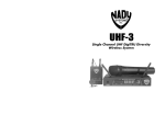
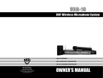
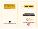
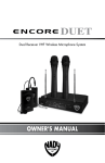
VHF Wireless Microphone System
DigiTRU Diversity™
CONTENTS
CONTENTS.....................................................................................................2
INTRODUCTION..............................................................................................2
USING THIS MANUAL......................................................................................2
SYSTEM FEATURES...........................................................................................3
ENCORE II RECEIVER........................................................................................4
WHT HANDHELD MICROPHONE TRANSMITTER.................................................7
WLT LAVALIER/LAPEL OR HEADWORN MICROPHONE
BODYPACK TRANSMITTER................................................................................9
WGT INSTRUMENT BODYPACK TRANSMITTER.................................................11
SPECIFICATIONS............................................................................................13
SERVICE INFORMATION.................................................................................14
WARRANTY...................................................................................................15
INTRODUCTION
Thank you for choosing the Nady Encore II diversity wireless microphone system,
we know you will be very pleased with its performance and features. The Encore II
is loaded with top professional operating features and is the best performance and
price value available in VHF dual receiver wireless systems.
USING THIS MANUAL
This booklet provides information regarding the use of the Encore II VHF wireless
system and includes a description of features and a step‑by‑step guide to operation of
the unit. This manual should answer any questions you may have about the operation
and servicing of your Encore II.
2
SYSTEM FEATURES
• Available on selected frequencies in the VHF high band
(171-216 MHz) for interference-free, long-range performance
• Proprietary companding circuitry for an industry-best 120dB Dynamic Range,
and the clearest, most natural sound available
• Operating Range: Up to 250 feet typical (depending on site conditions)—
up to 500+ feet line- of-sight
• Noise-free transmitter ON-OFF operation
ENCORE II RECEIVER
• Half-rack receiver design with retractable front panel dual antennas
• Proprietary DigiTRU Diversity™ digital processing circuitry to eliminate dropouts and maximize operating range
• RF and AF 5-LED displays for monitoring incoming signal strength and audio level
• Balanced XLR and unbalanced adjustable 1/4” jack outputs
• Mute (squelch) adjust control
• Externally powered by AC/DC power adapter
• Unique snap-out panel locking tabs for single receiver or dual receiver
(side-by-side) optional rack mounting
WHT HANDHELD MIC TRANSMITTER
• Features the Nady DM -10D unidirectional neodymium dynamic cartridge for optimum true sound, maximum feedback rejection and minimal handling noise
• OFF/STANDBY/ON switch allows convenient audio muting with the
transmitter “ON”
• Low battery LED indicator flashes once for unit “ON”; lights steady for low
battery alert
WGT & WLT BODYPACK TRANSMITTERS
• Choice of instrument (WGT) or headworn/lavalier microphone (WLT)
bodypack transmitter
• OFF/STANDBY/ON switch allows convenient audio muting with the
transmitter “ON”
• Low battery LED indicator flashes once for unit “ON”; lights steady for low battery alert
• Locking 3.5mm mini-jack provides secure connection for removable microphone
or instrument cable
• Easily accessible input level adjust control for optimum sound
3
ENCORE II RECEIVER
1. Rackmounting the Receiver
There are two options available for rackmounting the Encore II receiver:
singly or side-by-side with another Encore Series receiver.
a. Single mounting: Remove the receiver SIDE MOUNT CLIP (1) from each side of
the receiver (as shown) and slide in the optional ERM-12 RACK EARS (9).
b. Side-by-side double mounting: After removing the SIDE MOUNT CLIPS (1) from
both Encore receivers, join the two receivers with the EJC-2 JOINING CLIP (10)
and attach the ERM-22 RACK EARS (12) as shown.
(Note: Do not mount the receiver in a rack directly above an amplifier or
other source of high heat — this could degrade the performance of the
Encore I. Always ensure adequate airflow and heat dissipation in any rack
configuration.)
2. Powering the Receiver
Plug the 12V AC/DC ADAPTER (15) provided into the DC INPUT JACK (11) on
the back of the receiver. Then plug the power supply into an AC outlet.
(Note: Any 12V DC source with 400mA capability can also be used.)
Press the POWER SWITCH (8) once to turn on the receiver. The POWER ON LED (7)
will now light and the receiver is operational.
3. Antennas
The Encore II receiver is supplied with TELESCOPIC ANTENNAS (16). These should be
extended fully to obtain maximum range. Optimal antenna position is 45 degrees
from the receiver (at 90 degrees from each other). For maximum range, it is always
best to maintain a line of sight (no obstructions) between the receiver antennas and
the transmitter at all times whenever possible.
4. Mute (Squelch) Adjustment
In normal operation, the MUTE CONTROL (2) should be set fully counterclockwise to
the factory preset minimum RF level. However, in areas of high RF activity, the mute
(or squelch, as it is sometimes called) may need to be adjusted to compensate for the
adverse conditions in a particular location. If, with the transmitter off, the receiver’s
A and/or B DIVERSITY LED INDICATORS (3) and/or one or more LEDs of the 5 LED RF
LEVEL DISPLAY (4) flicker or stay on, the squelch control should be turned clockwise
until the LEDs extinguish. When the squelch is properly adjusted, the A and/or B
LEDs or the RF LEVEL LED displays will only light when the system transmitter is turned
on. Turning the squelch control too far clockwise will reduce the range, but yield a
quieter mute (squelch) function. During operation, especially at ranges greater than
75 feet, one or the other of the A or B LEDs may extinguish briefly. This is normal—
the unit’s DigiTRU Diversity™ reception ensures that the received audio will not be
interrupted. When both the A/B DIVERSITY LEDs and the 5 LED RF LEVEL display
extinguish, the transmitter is out of range for that given location, and the user should
move closer to the receiver to re-establish the radio link.
4
5. Connecting the Audio Output
The Encore II receiver provides both a fixed mic level BALANCED AUDIO OUTPUT XLR
(14) and an adjustable line level UNBALANCED AUDIO OUTPUT 1/4” JACK (13). The level
from the UNBALANCED OUTPUT is controlled by the rear panel VOLUME CONTROL (6).
(Note: As when making any connection, make sure the amplifier or mixing board
volume is at the minimum level before plugging in the receiver to avoid possible
sound system damage. Also make sure that the phantom power on the input of
the mixer is turned OFF before making connection to the receiver.)
a. Instrument Connection (using the WGT instrument transmitter)
Insert an audio cord with a 1/4" mono phone plug in the A + B
UNBALANCED OUTPUT JACK (13) on the rear panel of the receiver. Plug the
other end of the cord into an amplifier, effects, or mixing board. Adjust the
appropriate VOLUME CONTROL (6) for the channel being used on the Encore I
receiver clockwise to about 3/4 rotation, until the mixed volume level is
comfortable for your application. This setting is roughly equivalent to a direct
instrument cord connection. Turning the volume up to maximum will provide
4dB gain over a cord.
b. Microphone Connection (using the WLT transmitter with either a headset
or lavalier microphone or the WHT handheld microphone transmitter)
For microphone use, either the BALANCED MIC AUDIO OUTPUT XLRs (14) or the
1/4" line level A + B UNBALANCED OUTPUT (13) can be used. The XLR output
is set at a non-adjustable microphone level, similar to hardwired mic levels.
Plug an XLR connector into either or both of the XLR OUTPUT JACKS on the
rear of the unit and plug the other end into your amplifier or mixing board.
(Note: Make sure the phantom power on your mixing board is turned off
and the volume is turned down when making connections.)
For your convenience, the XLR output levels are preset at the factory and
are not adjustable with the receiver volume controls. To use the 1/4" A + B
UNBALANCED OUTPUT JACK (13), follow the instructions for the Instrument
Connection (above), except start with the receiver volume at 1/2 MAX
and adjust the volume control for each channel until the mixed Ch A and
Ch B volume level is optimal. If the volume controls are set too high, you
may overload your mixer or amp.
5
16
16
7
AF
RF
A
POWER
8
B
4
3
5
12-15V
UNBALANCED OUT DC INPUT
13
11
VOLUME
MUTE
BALANCED OUT
6
14
2
15
1
9
9
1
12
10
12
6
WHT HANDHELD MICROPHONE TRANSMITTER
1. Unscrew the BATTERY COMPARTMENT COVER (17) and remove, exposing the
BATTERY HOLDER (18). Insert a fresh 9V ALKALINE BATTERY (19), observing the
correct polarity as marked, and screw the cover back on to the microphone.
Make sure the cover is screwed on completely. A fresh alkaline battery can
last up to 16 hours in use, but in order to ensure optimum performance, it is
recommended that you replace the battery after every 10 hours of use.
2. Turn on the WHT by sliding the OFF/STANDBY/ON SWITCH (20) to the STANDBY
position (transmitter on, audio muted) or the ON position (transmitter and audio
both on). The BATTERY INDICATOR LED (21) will give a single quick flash, indicating
usable battery strength. In the case of a dead or low battery, the LED will either
not go on at all or will stay on continuously, indicating that the battery should be
replaced with a fresh one. To preserve battery life, turn the transmitter off when
not in use.
3. The microphone is now ready to use. The A and/or B DIVERSITY LED INDICATORS
(3) and most or all of the RF LEVEL DISPLAY LEDs (4) on the Encore II receiver
should now be lit, indicating a received signal from the transmitter. When ready
to speak, slide the transmitter switch to the ON position. Adjust the volume
of the receiver as per the Audio Output Microphone Connection section of
the above Encore II receiver instructions. The AF LEVEL LED DISPLAY (5) on the
Encore II receiver will light up to 5 LEDs (4 green and 1 red) for all input signals.
Occasional flickering on and off during use of the top red LED indicator in this
display is normal, however if the red LED stays on continuously, it means the
signal is too loud and there is the possibility of overload distortion. Back off from
the microphone until the red LED indicator only flickers on peaks.
[Note: Observe care in selecting P.A. volume, transmitter location and speaker
placement so that acoustic feedback (howling or screeching) will be avoided.]
[Note: Microphone elements can easily be destroyed by the buildup of salts and
minerals from perspiration and saliva. It is good practice to put a windscreen on
the mic element at all times to protect it.]
7
21
20
18
19
17
8
WLT LAVALIER/LAPEL OR HEADWORN
MICROPHONE BODYPACK TRANSMITTER
1. Snap open the BATTERY COMPARTMENT (22) and insert a fresh 9V BATTERY (23),
observing the correct polarity. Close the compartment.
2. The WLT is provided with a 3.5 mm LOCKING JACK (24) for connecting the
microphone. Plug in either the LAVALIER/LAPEL (25) or the HEADWORN
MICROPHONE (26), as supplied. To secure the connection, turn the metal slip ring
on the plug clockwise to thread it on to the jack. To unplug, reverse the process.
Slip the transmitter into a pocket or clip on to your clothes. To use the lavalier mic,
attach it at chest level. Do not place too close to the mouth—a distance of about
six inches usually works best. To use the headworn mic, place it on the head and
adjust the mic boom so that the mic is about one inch to the side of the front of
the mouth. (Note: The lavalier or headworn mic wire is also the transmit antenna,
and rolling up or shortening the wire may reduce the effective operating range.
Extend the wire fully during use, and keep it as straight as possible.)
3. Turn on the WLT by sliding the OFF/STANDBY/ON SWITCH (27) to the STANDBY
position (transmitter on, audio muted) or the ON position (transmitter and audio
both on). The BATTERY INDICATOR LED (28) will give a single quick flash, indicating
usable battery strength. In the case of a dead or low battery, the LED either will
not go on at all or will stay on continuously, indicating that the battery should be
replaced with a fresh one.
4. The microphone is now ready to use. Most or all of the RF DISPLAY LEDs (4) on
the Encore II receiver should now be lit, indicating a received signal from the
transmitter. When ready to speak, slide the transmitter switch to the ON position
and adjust the volume of the receiver as per the Audio Output Microphone
Connection section of the above Encore II receiver instructions. The AF LEVEL
LED DISPLAY (5) on the Encore II receiver will light up to 5 LEDs (4 green and
1 red) for all input signals. Occasional flickering on and off during use of the
top red LED indicator in this display is normal, however if the red LED stays
on continuously, it means the signal is too loud and there is the possibility of
overload distortion. Re-position the microphone farther from the source or adjust
the AUDIO INPUT LEVEL CONTROL (29) until the red LED indicator flickers only on the
loudest inputs.
(Note: Observe care in selecting P.A. volume, transmitter location and
speaker placement so that acoustic feedback (howling and screeching) will be
avoided. Please also observe the pickup patterns of the microphone selected:
omnidirectional mics pick up sound equally from all directions and are prone to
feedback if not used carefully. Unidirectional mics are more resistant to feedback,
but pick up sound sources best that are directly in front of the mic. Also, mics
that are farther from the sound source, such as lavaliers, require more acoustic
gain and thus are also more prone to feedback than close-source mics such as
handheld or headworn mics that are used close to the mouth.)
(Note: Microphone elements can easily be destroyed by the buildup of salts and
minerals from perspiration and saliva. It is good practice to put a windscreen on
the mic element at all times to protect it.)
9
24
29
28
W
T
BA HI
27
MIC
N
Y/O
DB
TAN
F/S
OF
LO
22
25
26
22
Opening Battery Compartment
23
10
WGT INSTRUMENT BODYPACK TRANSMITTER
1. Snap open the BATTERY COMPARTMENT (30) and insert a fresh 9V BATTERY (31),
observing the correct polarity. Close the compartment. The WGT is provided
with a 3.5 mm LOCKING JACK (32) for connecting the INSTRUMENT CABLE (35).
To secure the connection, turn the metal slip ring on the plug clockwise to thread
it on to the jack. To unplug, reverse the process. Slip the transmitter into a pocket
or clip on to your clothes or instrument strap. (Note: As the cord to the instrument
also serves as the antenna, be sure to extend it fully for maximum range.
Rolling up or shortening the cord may reduce the effective operating range.)
2. Turn on the WGT by sliding the OFF/STANDBY/ON SWITCH (32) to the STANDBY
position (transmitter on, audio muted) or the ON position (transmitter and audio
both on). The BATTERY INDICATOR LED (33) will give a single quick flash, indicating
usable battery strength. In the case of a dead or low battery, the LED either will
not go on at all or will stay on continuously, indicating that the battery should be
replaced with a fresh one.
3. The WGT transmitter is now ready to use. The A and/or B DIVERSITY LED
INDICATORS (3) and most or all of the RF DISPLAY LEDs (4) on the Encore II receiver
should now be lit, indicating a received signal from the transmitter. Adjust the
volume of the receiver as per the Audio Output Instrument Connections section of
the above Encore II receiver instructions. For optimum performance, an INPUT
LEVEL CONTROL (34) is provided on the top panel of the WGT. Adjust the gain by
turning the control with a small slot head screwdriver. It is recommended that this
control be turned to maximum gain. However, for ultra high-gain instrument
sources such as active bass pickups or even extra hot guitar pickups, turning the
level down slightly will create a cleaner sound.
(Note: Turning down the input gain too much can compromise the signal-to-noise
ratio and is not recommended. Set for the maximum possible gain and headroom
without noticeable distortion on the high level peaks).
The AF LEVEL LED DISPLAY (5) on the Encore II receiver will light up to 5 LEDs (4
green and 1 red) for all input signals. Occasional flickering on and off during
use of the top red LED indicator in this display is normal, however if the red LED
stays on continuously, turn down the instrument volume or adjust the INPUT LEVEL
CONTROL (34) on the WGT transmitter, or noticeable distortion may result.
(Note: Scratchy noises can sometimes occur when some electric guitars/basses
with dirty pots or connections are used with any wireless system. For this reason,
the supplied INSTRUMENT CORD (35) has a factory installed capacitor inside
the 1/4" plug. This capacitor provides first order filtering of the RF signal from
the cord into the guitar and eliminates virtually all scratchy noises. Should your
equipment still give you scratchy noises, we suggest these steps to eliminate them:
1)
2)
Make sure all guitar volume and tone pots are clean and all contacts
are solid—this is very important.
Provide extra filtering with a 220 pF capacitor soldered across the
hot to ground terminals of the guitar's volume and tone pots.)
11
35
34
33
32
30
30
Opening Battery Compartment
31
12
SPECIFICATIONS
ENCORE II OVERALL SYSTEM PERFORMANCE
Reception Mode
DigiTRU Diversity™
Controls
Power ON/OFF, volume control, mute control
Connectors Balanced XLR and unbalanced adjustable
1/4” audio out jacks, 2.1 mm barrel-type DC input jack
LED Indicators Power ON, 5-LED RF & AF level displays, A/B Diversity
Dimensions (Max.)
1.75” x 7.5” x 8.1” (4.4 x 19 x 20.7 cm) Weight 1.6 lbs (.73 kg)
Power Requirements
12V @ 400mA, nominal, AC/DC adapter supplied
Antenna
11.2” (28.5 cm), dual telescopic
ENCORE II RECEIVER
Controls
Connectors LED Indicators Dimensions (Max.)
Weight Power Requirements
Antenna
TRANSMITTERS
Audio Inputs
• WHT
• WLT/WGT
Controls
• WHT
• WLT/WGT
LED Indicator RF Power Out Harmonic & Spurious Emissions
Battery
Battery Life
Dimensions
• WHT
• WLT/WGT
Weight (w/o battery)
• WHT
• WLT/WGT
Power ON/OFF, volume control, mute control
Balanced XLR and unbalanced adjustable 1/4”
audio out jacks, 2.1 mm barrel-type DC input jack
Power ON, 5-LED RF & AF level displays ,
1.75” x 7.5” x 8.1” (4.4 x 19 x 20.7 cm) 1.6 lbs (.73 kg)
12V @ 400mA, nominal,
AC/DC adapter supplied
11.2” (28.5 cm), single telescopic
Nady DM-10D neodymium dynamic cartridge
3.5mm mono locking jack for connecting to omni
or unidirectional lavalier mic or unidirectional
head worn mic, with phantom power (WLT);
or connecting to instrument cable (WGT)
OFF/STANDBY/ON switch
OFF/STANDBY/ON switch, input level adjust
Unit “ON” (single flash), Low Battery Alert (steady)
50mW (Max. allowed by FCC)
> –40dB
9V Alkaline
Up to 15 hours
9.5” X 1.4” Diam. (24.1 X 3.5 cm)
4.1” X 2.4”X 0.8” (10.4 X 6.1 X 2.0 cm)
6.9 oz (193 g)
3.6 oz (101 g)
Specifications subject to change at any time without prior notice for purposes of product improvement
13
SERVICE INFORMATION
In the U.S. If you are experiencing operational problems with your system, please
refer to the Support page at www.nady.com for assistance. Should your wireless
system require service, please contact the Nady Service Department at (510)
652-2411 to obtain a Return Authorization (R/A) Number and service quote (if out
of warranty). Make sure the R/A Number is clearly marked on the outside of the
package that you are returning.
If your unit is out of warranty, please enclose a cashier’s check or money order (or
pay by credit card) per instructions by the Nady Service Department. Ship your unit
prepaid to: Nady Systems, Service Department, 6701 Shellmound Street, Emeryville,
CA 94608. Include a brief description of the problem you are experiencing. For
service of a unit under warranty, please follow the instructions in the following
section.
Outside the U.S. For service or warranty matters please contact the Nady distributor
in your country through the dealer/store from which you purchased this product.
Do not attempt to service this unit yourself as
it can be dangerous and will also void the warranty.
14
ONE-YEAR LIMITED WARRANTY
Nady Systems, Inc. warrants to the original consumer purchaser that the unit is free from
any defects in material or workmanship for a period of one year from the date of original
retail purchase. If any such defect is discovered within the warranty period, Nady Systems,
Inc. will repair or replace the unit free of charge, subject to verification of the defect or
malfunction upon return to Nady Systems. Please do not return your Nady product to the
store where it was purchased as Nady Systems handles your warranty service directly.
Communication with our Service Department is the most efficient means of servicing your unit
and we are dedicated to keeping you a satisfied customer.
To the extent permitted by law, any applicable implied warranties, including warranties
of merchantability and fitness are hereby limited to one year from the date of purchase.
Consequential or incidental damages resulting from a breach of any applicable express or
implied warranties are hereby excluded. This warranty is in lieu of all other agreements and
warranties, general or special, express or implied and no representative or person including
a Nady dealer, agent, or employee is authorized to assume for us any other liability in
connection with the sale or use of this Nady Systems’ product.
Whereas some states do not allow limitations on how long implied warranties last, and
do not allow exclusion of incidental or consequential damages, the above limitations and
exclusions may not apply to you. This warranty gives you specific legal rights and you may
also have other rights which may vary from state to state.
This warranty is subject to the following conditions:
1) This system must have been purchased from an authorized Nady dealer and all warranty
service must be performed by Nady’s service department. Any service not performed by
Nady will automatically void this warranty.
2) Items not covered: physical damage resulting from improper handling of the unit in
transit from the factory by the shipper (Nady Systems is not responsible for such damage
and all such claims must be made against the shipping company by the consignee); defects
caused by normal wear of the product (expendable parts are typically connectors, cables,
potentiometers, switches and similar components); damage or defects caused by abuse,
neglect, accident, failure to connect or operate the unit in any way that does not comply with
applicable technical or safety regulations, or improper repair, excessive heat or humidity,
alteration or unreasonable use of the unit, causing cracks, broken cases/housings or parts;
damage caused by leaking batteries; finish or appearance items; items damaged in shipment
en route to Nady Systems, Inc. for repair. The warranty is null and void if any Nady serial
number has been removed or defaced.
How To Obtain Service:
1) If factory service is required, please contact our Service Department at (510) 652-2411
for a return authorization (R/A) number. Make sure the R/A number is clearly marked on
the outside of your package. (Please note: if an R/A number is not included, our Shipping
Department cannot accept your package.)
2) Send the unit back to Nady Systems, 6701 Shellmound Street, Emeryville, CA, 94608,
freight pre-paid. You must include proof of date and place of purchase (i.e., photocopy
of your bill of sale) or Nady cannot be responsible for repair or replacement. Nady
Systems, Inc. will not repair, nor be held responsible, for any units returned without proper
identification, return address, and R/A number clearly marked on the package.
3) Per the above, Nady will perform all warranty service and return the unit to you at no
charge. Nady Systems will inform the buyer if product sent in does not meet the terms of this
warranty and will provide a quote for fixing the unit and/or shipping it back exclusively at
the buyer’s expense.
15
Nady Wireless Systems are type accepted under FCC rules parts 90, 74 and
15. The device complies with RSS-210 of Industry & Science Canada. Operation
is subject to the following two conditions: (1) this device may not cause harmful
interference and (2) this device must accept any interference received, including
interference that may cause undesired operation.
6701 Shellmound Street | Emeryville, CA USA 94608
T 510.652.2411 | F 510.652.5075 | www.nady.com