1
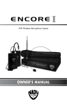
UHF-4
Single Channel UHF DigiTRU Diversity™
Wireless System
OWNER'S MANUAL
UHF4_man
1
2/15/05, 4:09 PM
CONTENTS
CONTENTS ........................................................................................... 2
INTRODUCTION .................................................................................... 2
USING THIS MANUAL ............................................................................ 2
SYSTEM FEATURES ................................................................................ 3
UHF-4 RECEIVER .................................................................................... 4
UH-4 HANDHELD MICROPHONE TRANSMITTER ...................................... 7
UB-4 BODYPACK MICROPHONE TRANSMITTER ...................................... 8
SPECIFICATIONS ................................................................................. 11
SERVICE ................................................................................. Back Cover
INTRODUCTION
Thank you for purchasing a Nady UHF-4 Diversity Wireless Microphone System and
congratulations on your choice. The UHF-4 is loaded with top professional operating
features and is the best performance and price value available in UHF diversity
wireless systems.
USING THIS MANUAL
This booklet gives instructions for the operation of the UHF-4 wireless, including
handheld, instrument, lavalier, headmic and plug-in transmitter systems. Please read
the instructions for your system completely before operating unit.
This manual will first list the features of the UHF-4 and then will take you step by step
to show you how to operate your new system. After reading the receiver instructions,
turn to the section of the booklet that covers the type of transmitter used with your new
system. Each section will give you detailed operating instructions. Also included in this
manual are system specifications and servicing information.
2
UHF4_man
2
2/15/05, 4:09 PM
SYSTEM FEATURES
UHF-4 RECEIVER
• Unprecedented value in a full-featured single-channel UHF wireless mic system
— with interference-free operation in any application or locale on select UHF
frequencies within separate bands 902-928 and 944-952 MHz
• Half-rack receiver design with folding front panel dual antennas and
unique snap-out panel locking tabs for single receiver or dual receiver (sideby-side) optional rack mounting
• Nady’s proprietary companding circuitry for an industry best 120dB
Dynamic Range, and the clearest, most natural sound available
• Tone Squelch™ for locking out potential interference
• UHF-4 receiver with DigiTRU Diversity™ for maximum range and
dropout protection, full LED indicators, both 1/4" unbalanced and XLR
balanced outputs, and special circuitry for noiseless transmitter
ON/OFF switching
• Mute (squelch) adjust control
• Externally powered by AC/DC power adapter
UH-4 HANDHELD MIC TRANSMITTER
• Features the Nady DM -10D unidirectional neodymium dynamic cartridge for
optimum true sound, maximum feedback rejection and minimal handling noise
• OFF / STANDBY / ON switch allows convenient audio muting with the
transmitter “ON”
• Status LED indicator flashes once for unit "ON"; lights steady for
low battery alert
• Easily accessible input level adjust control for optimum sound
• 9V alkaline or NiMH battery operation —rubber mic clip available as option
UB-4 BODYPACK TRANSMITTER
• Choice of instrument or headworn/lavalier microphone bodypack transmitter
in a single unit
• OFF / STANDBY / ON switch allows convenient audio muting with the
transmitter “ON”
• Status LED indicator flashes once for unit "ON"; lights steady for
low battery alert
• Locking 3.5mm mini-jack provides secure connection for removable
microphone or instrument cable
• Easily accessible input level adjust control for optimum sound
• 9V alkaline or NiMH battery operation
3
UHF4_man
3
2/15/05, 4:09 PM
UHF-4 RECEIVER
1. Rackmounting the Receiver
There are 2 options available for rackmounting the UHF-4 receiver: singly or side-byside with another UHF-4 Series receiver.
a. Single mounting: Remove the receiver SIDE MOUNT CLIP (1) from each side of
the receiver (as shown) and slide in the optional ERM-3 RACK EARS (2).
b. Side-by-side double mounting: After removing the SIDE MOUNT CLIPS (1) from
both UHF-4 receivers, join the two receivers with the EJC-3 JOINING CLIP
(3) and attach the ERM-33 RACK EARS (4) as shown. (Note: Do not mount
the receiver in a rack directly above an amplifier or other source of high heat –
this could degrade the performance of the UHF-4. Always ensure adequate
airflow and heat dissipation in any rack configuration.)
2. Powering the Receiver
Plug the 15V/0.3A AC/DC ADAPTER (5) provided into the DC INPUT JACK (9) on the
back of the receiver. Then plug the power supply into an AC outlet. Press the POWER
SWITCH (11) once to turn on the receiver. The POWER ON LED (12) will now light
and the receiver is operational.
3. Antennas
The UHF-4 receiver is supplied with FOLDING ANTENNAS (15). These should be
extended fully to obtain maximum range. Optimal antenna position is 45 degrees
from the receiver (at 90 degrees from each other). For maximum range, it is always
best to maintain a line of sight (no obstructions) between the receiver antennas and
the transmitter at all times whenever possible.
4. Mute (Squelch) Adjustment
In normal operation, the SQUELCH CONTROL (6) should be set fully clockwise to the
factory preset RF level (Max. Sens.). However, in areas of high RF activity, the squelch
(or mute, as it is sometimes called) may need to be adjusted to compensate for the
adverse conditions in a particular location. If, with the transmitter off, the receiver’s A
and/or B DIVERSITY LED INDICATORS (13) flicker or stay on, the squelch control
should be turned counterclockwise until the A and/or B LEDs extinguish. When the
squelch is properly adjusted, the A or B LEDs will only light when the transmitter is
turned on. Turning the squelch control too far counterclockwise will reduce the range,
but yield a quieter squelch (mute) function. During operation, especially at ranges
greater than 75 feet, one or the other of the A or B LEDs may alternate briefly. This is
normal–the unit’s DigiTRU Diversity™ reception ensures that the received audio will
not be interrupted. When both LEDs extinguish, the transmitter is out of range for that
given location, and the user should move closer to the receiver to re-establish the
radio link.
4
UHF4_man
4
2/15/05, 4:09 PM
5. Connecting the Audio Output
The UHF-4 receiver provides both a fixed mic level BALANCED MIC AUDIO OUTPUT
XLR (7) and an adjustable line level AUX AUDIO OUTPUT 1/4" jack (10).
(Note: As when making any connection, make sure the amplifier or mixing board
volume is at the minimum level before plugging in the receiver to avoid possible
sound system damage.)
Microphone Connection
(using the UB-4 transmitter with either a headworn or lavalier microphone or the
UH-4 handheld microphone transmitter) For microphone use, either the BALANCED
MIC AUDIO OUTPUT XLR (7) or the 1/4" line level AUX AUDIO OUTPUT (10) can be
used. The XLR output is set at a non-adjustable microphone level, similar to hardwired
mic levels. Plug an XLR connector into the XLR output socket on the rear of the unit
and plug the other end into your amplifier or mixing board. Make sure the phantom
power on your mixing board is turned off and the volume is turned down when
making connections. For your convenience, the XLR output level is preset at the
factory and is not adjustable with the receiver volume control.
To use the 1/4" AUX AUDIO OUTPUT socket, follow the instructions for the Instrument
Connection (above), except start the receiver volume at 1/2 MAX and adjust until the
volume level is optimal. If the volume control is set too high, you may overload your
mixer or amp.
The UHF-4 receiver is equipped with a 5 segment LED AF LEVEL DISPLAY (14).
Occasional flickering of the top AF Peak LED indicator on loud inputs to the
transmitter is normal. If this LED lights continuously, decrease the volume to the
transmitter or overload distortion may result.
5
UHF4_man
5
2/15/05, 4:10 PM
15
15
12
13
11
9
10
14
8
7
5
6
1
2
2
1
4
3
4
6
UHF4_man
6
2/15/05, 4:10 PM
UH-4 HANDHELD MICROPHONE TRANSMITTER
1. Unscrew the BATTERY COMPARTMENT COVER (16) and remove, exposing the
BATTERY HOLDER (17). Insert a fresh 9V ALKALINE BATTERY (18), observing the
correct polarity as marked, and screw the cover back on to the microphone. Make
sure the cover is screwed on completely. Fresh alkaline batteries can last up to 10
hours in use, but in order to ensure optimum performance, it is recommended that
you replace the battery after every 6-8 hours of use.
2. Turn on the UH-4 by sliding the OFF/STANDBY/ON SWITCH (19) to the
STANDBY position first (transmitter on, audio muted) or the ON position (transmitter
and audio both on). The BATTERY INDICATOR LED (20) will give a single quick flash,
indicating usable battery strength. In the case of a dead or low battery, the LED will
either not go on at all or will stay on continuously, indicating that the battery should
be replaced with a fresh one. To preserve battery life, turn the transmitter off when
not in use.
3. The microphone is now ready to use. The A or B DIVERSITY LED INDICATORS (13)
on the UHF-4 receiver should now be lit, indicating a received signal from the
transmitter. When ready to speak, slide the OFF/STANDBY/ON SWITCH (19) to the
ON position. Adjust the volume of the receiver as per the Audio Output Microphone
Connection section of the above UHF-4 receiver instructions.
[Note: Observe care in selecting P.A. volume, transmitter location and speaker
placement so that acoustic feedback (howling or screeching) will be avoided.]
4. For optimum performance, an INPUT LEVEL CONTROL (21) is provided. Adjust the
gain by turning the control with a small screw driver. Set for maximum possible gain
without audible distortion on the high level peaks. (Note: Turning down the gain too
much can compromise the signal-to-noise and is not recommended.)
17
18
20
16
19
21
7
UHF4_man
7
2/15/05, 4:10 PM
UB-4 BODYPACK MICROPHONE TRANSMITTER
1. Snap open the BATTERY DOOR (22) and insert a fresh 9V alkaline battery into the
BATTERY COMPARTMENT (23), observing the correct polarity. Fresh alkaline
batteries can last up to 10 hours in use, but in order to ensure optimum performance,
it is recommended that the battery be replaced after 6-8 hours of use.
2. The UB-4 is equipped with two INPUT SELECTOR SWITCHES (24) located under the
cover on the circuit board for selecting the type of audio input you will be supplying
to the transmitter. Select from the choice of three positions: INSTRUMENT (for guitar,
bass, etc.)/ HEADWORN MIC/ LAVALIER MIC. (G/H/L).
There are two switches, one with selectable position G, H, L and the other with G, HL.
To select inputs: (see chart on page 10)
A. Instrument — both switches to “G”
B. Headworn Mic — set one switch to “H” and the other to “H”
C. Lavalier Mic — set one switch to “L” and the other to “L”
3. The UB-4 is provided with a 3.5 mm LOCKING JACK (25) for connecting the audio
input selected. Connect either the INSTRUMENT CORD (30) or the HEADWORN MIC
(31) or LAVALIER MIC CORD (32) as desired, according to the input selected. (Note:
Use only the input audio source as per the input selected with the internal AUDIO
INPUT SELECTOR SWITCHES (24) or the audio will not be optimal–a muddy or
distorted sound may result.) To secure the connection, turn the slip ring on the plug
clock wise to thread it on the jack. To unplug, reverse the process. Slip the transmitter
into a pocket or CLIP (29) it on to your clothes or instrument strap (if using the UB-4
as an instrument transmitter).
4. Turn on the UB-4 by sliding the OFF/STANDBY/ON SWITCH (26) to the STANDBY
position (transmitter on, audio muted) or the ON position (transmitter and audio both
on). The BATTERY INDICATOR LED (27) will give a single quick flash, indicating
usable battery strength. In the case of a dead or low battery, the LED either will not
go on at all or will stay on continuously, indicating that the battery should be
replaced with a fresh one.
5. The UB-4 transmitter is now ready to use. The A or B DIVERSITY LED INDICATORS
(13) on the UHF-4 receiver should now be lit, indicating a received signal from the
transmitter. Adjust the volume of the receiver as per the Audio Output Instrument
Connections section of the above UHF-4 receiver instructions. For optimum
performance, an INPUT LEVEL CONTROL (28) is provided on the top panel of the UB4. Adjust the gain by turning the control with a small slot head screwdriver.
It is recommended that this control be turned to maximum gain. However, for ultra
high-gain instrument sources such as active bass pickups or even extra hot guitar
pickups, turning the level down slightly will create a cleaner sound. (Note: Turning
down the input gain too much can compromise the signal-to-noise ratio and is not
recommended. Set for the maximum possible gain and headroom without noticeable
distortion on the high level peaks).
The AF LEVEL LED DISPLAY (13) on the UHF-4 receiver will light up to 5 LEDs (4
green and 1 red) for all input signals. Occasional flickering on and off during use of
the top red LED indicator in this display is normal, however if the red LED stays on
continuously, turn down the instrument volume or adjust the INPUT LEVEL CONTROL
(28) on the UB-4 transmitter, or noticeable distortion may result.
8
UHF4_man
8
2/15/05, 4:10 PM
6. Instrument Use
Secure the connection from the GT CABLE (30) by turning the slip ring on the plug
into the transmitter clockwise to thread it on the jack. To unplug, reverse the process.
Plug the 1/4” phone plug into the instrument. When ready to play, slide the audio
MUTE SWITCH (26) to “ON” position Adjust the volume of the receiver as per the
Audio Output Instrument Connection section of the above UHF-4 receiver instruction.
(Note: The INPUT LEVEL CONTROL (28) is deactivated and not used when the UB-4 is
in INSTRUMENT mode. Levels should be adjusted with the volume control of your
instrument.)
(Note: Scratchy noises can sometimes occur when some electric guitars with dirty pots
or connections are used with any wireless system. Therefore, the supplied
INSTRUMENT CORD (30) has a factory installed capacitor inside the 1/4" plug. This
capacitor provides first order filtering of the RF signal from the cord into the guitar
and eliminates virtually all scratchy noises. Should your equipment still give you
scratchy noises, we suggest these steps to eliminate them:
1) Make sure all guitar volume and tone pots are clean and all contacts are solid–this
is very important.
2) A 47pf capacitor soldered across the hot to ground terminals of the guitar’s
volume and tone pots will provide extra filtering.)
7. Microphone Use (with either a lavalier or headworn microphone)
Secure the connection from the LAVALIER (32) or HEADWORN MIC CORD (31) by
turning the slip ring on the plug into the transmitter clockwise to thread it on to the
jack. To unplug, reverse the process. To use the lavalier mic, attach it at chest level.
Do not place it too close to the mouth–a distance of about six inches usually works
best. To use the headworn mic, place it on the head and adjust the boom so that the
mic is about one inch to the side of the front of the mouth. As the microphone cord
also serves as the antenna, be sure to extend it fully. Rolling up or shortening the cord
may reduce the effective operating range–keep it as straight as possible. When ready
to speak, slide the OFF/STANDBY/ON SWITCH (26) to the ON position. Adjust the
volume of the receiver as per the Audio Output Microphone Connection section of the
above UHF-4 receiver instruction. [Note: Observe care in selecting P.A. volume,
transmitter location and speaker placement so that acoustic feedback (howling and
screeching) will be avoided. Please also note the pickup pattern characteristics of the
microphone selected. Omnidirectional mics pick up sound equally from all directions,
and are prone to feedback if not used carefully. Unidirectional mics are more
resistant to feedback, but pick up sound sources best that are directly in front of the
mic. Also, mics that are farther from the sound source, such as lavaliers, require more
acoustic gain and thus are also more prone to feedback than close-source mics such
as handheld or headworn models that are used close to the mouth].
For optimum performance, an INPUT LEVEL CONTROL (28) is provided. Adjust the
gain by turning the control with a small screw driver. For lavalier mic use, it is
recommended that the level be set at about 1/2 maximum. For headworn mic use, it
may be advisable to turn the gain down somewhat, depending on the volume levels
expected. In either application, experiment and set for maximum possible gain
without audible distortion on the high level peaks. (Note: Turning down the gain too
much can compromise the signal-to-noise and is not recommended.)
9
UHF4_man
9
2/15/05, 4:10 PM
INPUT SELECTOR
SWITCHES
25
HL
Instrument
G G H L
HL
27
Headworn
26
G G H L
HL
Lavalier
28
G G H L
29
24
22
Opening Battery Compartment
30
23
31
32
10
UHF4_man
10
2/15/05, 4:10 PM
SPECIFICATIONS
UHF-4 OVERALL SYSTEM PERFORMANCE
30 Hz - 18 KHz, +/– 3 dB
120 dB
< 0.6%
UHF, choice of single frequencies within separate bands
902-928 and 944-952 MHz
+/- 0.005%, crystal controlled
FM (F3E), +/-20KHz normal
Up to 250 ft. typical (depending on site conditions); up to
500+ feet optimum line-of-sight
Frequency Response
Dynamic Range
Total Harmonic Distortion
RF Carrier Frequency Range
Frequency Stability
Modulation
Operating Range
RECEIVER
DigiTRU Diversity™ (Dual Antenna)
External Control, Tone Key (30.768 KHz)
Power ON/OFF, Volume Control, Squelch (Mute) Adjust
DC in, 1/4”(6.3 mm) unbalanced phone jack (360 mV/
no load), XLR balanced output (+/-24 mV/600 Ohm load)
Power ON, Diversity A/B, Audio LED Bars + Peak
60dB image and spurious
DC 15V @ 300 mA, AC/DC adapter included
1.75" x 7.5" x 8.1" (4.5 x 19 x 20.6 cm)
0.9 lbs (0.41 kg)
3.5" (9.0 cm), dual telescopic
Reception Mode
Squelch
Controls
Connectors
LED Indicators
Unwanted Signal Rejection
Power Requirements
Dimensions (Max.)
Weight
Antenna
TRANSMITTERS
Audio Inputs
Controls
LED Indicator
RF Power Out
Harmonic & Spurious Emissions
Battery
Battery Life
Dimensions
Weight
UB-4 Bodypack: 3.5mm locking mini-jack,
switchable inputs: instrument, headworn mic,
or lavalier mic
UH-4 Handheld: Integral Nady DM-10D neodymium
dynamic cartridge
UB-4: POWER/STANDBY/OFF, INSTRUMENT/
HEADWORN MIC/LAV MIC, INPUT LEVEL
UH-4: POWER/STANDBY/OFF/INPUT LEVEL
Single color (red), Unit “ON” (single flash red), Low Battery
Alert (steady red)
50mW nominal (maximum allowed by FCC)
< –50 dB
UH-4: 9V Alkaline UB-4: 9V Alkaline
10 Hours
UB-4 Bodypack: 4.25” x 2.5”x 1.0”
(10.8 cm x 6.4 cm x 2.5 cm)
UH-4 Handheld: 9.5”x 2.0”
(24 cm x 5.1 cm)
UB-4 Bodypack: 3.1 oz (88 g) without battery
UH-4 Handheld: 6.6 oz (187 g) without battery
11
UHF4_man
11
2/15/05, 4:10 PM
SERVICE
(U.S.) Should your Nady Wireless Microphone System require service, please contact
the Nady Service Department via telephone at (510) 652-2411 or e-mail to
[email protected] for a Return Authorization (R/A) Number and a service quote (if
out of warranty). Make sure the R/A Number is clearly marked on the outside of the
package and enclose a cashier's check or money order (if not prepaid with a credit
card). Ship the unit prepaid to: Nady Systems, Inc., Service Department, 6701
Shellmound Street, Emeryville, CA 94608. Include a brief description of the problems
you are experiencing.
The warranty card enclosed with this system contains additional valuable
warranty and service information. Keep it in a safe place for future possible
reference. Do not attempt to service this unit yourself as it will void the warranty.
(International) For service, please contact the Nady distributor in your country
through the dealer from whom you purchased this product.
Nady Wireless Systems are type accepted under FCC rules parts 90, 74 and 15. The
device complies with RSS-210 of Industry & Science Canada. Operation is subject to
the following two conditions: (1) this device may not cause harmful interference and (2)
this device must accept any interference received, including interference that may
cause undesired operation.
NADY SYSTEMS, INC.
6701 Shellmound Street • Emeryville, CA 94608 USA
Tel: 510/652-2411 • Fax: 510/652-5075
www.nady.com
UHF4_man
12
2/15/05, 4:10 PM