1
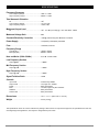
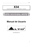
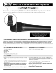
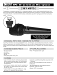
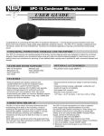
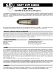
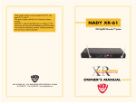
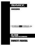
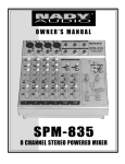
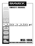
CROSSOVER
OWNER’S MANUAL
CX-2314
3-WAY STEREO, 4-WAY MONO
ACTIVE CROSSOVER
CX-2314
3-WAY STEREO, 4-WAY MONO ACTIVE CROSSOVER
Congratulations on your choice of crossover — you have purchased one of the finest stereo crossovers on the market today.
This unit was developed using the expertise of professional sound engineers and working musicians. You will find that your
new NADY AUDIO CX-2314 has superior performance and greater flexibility than any other crossovers in its price range.
Please read this manual carefully to get the most out of your new unit.
Thanks for selecting NADY AUDIO as your choice in crossovers.
FEATURES
CONTENTS
The CX-2314 crossover provides precise frequency dividing for
multi-amplified speaker applications, and is a valuable tool in
many professional live sound applications. It offers all the features needed to meet the most exacting requirements.
Features ..............................................................................3
This manual contains all the information you’ll need to fully utilize your crossover.
Front Panel Controls............................................................5
Warning................................................................................4
Rear Panel Connections......................................................6
• 3-Way Stereo or 4-Way Mono operation
• Single rack space (1U)
Operation ............................................................................7
• Shielded internal power supply with AC voltage select
switch (~115V/60Hz or ~230V/50Hz)
Typical Setup ......................................................................8
• Phase inversion switches
Specifications ......................................................................9
• Low-cut subsonic filters for low frequency driver protection
Notes ..................................................................................10
• Servo-balanced XLR inputs/outputs balanced operation
• State-variable Linkwitz Riley 24dB/octave filters
Date of Purchase____________________________________________
• Switchable constant directivity horn equalization circuit for
use with horns requiring a high frequency boost
Dealer’s Name______________________________________________
• Allows low summing of all or any of the low outputs
City ______________________________________________________
• Peak LED indicators
• Mute switches
State __________________________Zip ________________________
• Designed for the most precise accurate control
Model # __________________________________________________
• Top audio performance with high slew rate circuitry and
115dB dynamic range for clear transparent sound
Serial #
3
__________________________________________________
WARNING
An equilateral triangle enclosing a lightening flash/arrowhead symbol is
intended to alert the user to the presence of uninsulated “dangerous
voltage” within the product’s enclosure which may be of sufficient
magnitude to constitute a risk of electric shock.
ATTENTION: RISQUE DE CHOC ELECTRIQUE NE PAS OUVRIR
An equilateral triangle enclosing an exclamation point is intended to alert
the user to the presence of important operating and service instructions in
the literature enclosed with this unit.
IMPORTANT SAFETY INSTRUCTIONS
When using this electronic device, basic precautions should always be taken, including the following:
1. Read all instructions before using the product.
2. Do not use this product near water (e.g., near a bathtub, washbowl, kitchen sink, in a wet basement, or near a
swimming pool, etc.).
3. This product should be used only with a cart or stand that will keep it level and stable and prevent wobbling.
4. This product, in combination with headphones or speakers, may be capable of producing sound levels that
could cause permanent hearing loss. Do not operate for a long period of time at a high volume level or at a
level that is uncomfortable. If you experience any hearing loss or ringing in the ears, you should consult an
audiologist.
5. The product should be positioned so that proper ventilation is maintained.
6. The product should be located away from heat sources such as radiators, heat vents, or other devices
(including amplifiers) that produce heat.
7. The product should be connected to a power supply only of the type described in the operating instructions or
as marked on the product. Replace the fuse only with one of the specified type, size, and correct rating.
8. The power supply cord should: (1) be undamaged, (2) never share an outlet or extension cord with other
devices so that the outlet’s or extension cord’s power rating is exceeded, and (3) never be left plugged into
the outlet when not being used for a long period of time.
9. Care should be taken so that objects do not fall into, and liquids are not spilled through, the enclosure’s
openings.
10. The product should be serviced by qualified service personnel if:
A.
The power supply cord or the plug has been damaged.
B.
Objects have fallen into, or liquid has been spilled onto the product.
C. The product has been exposed to rain.
D. The product does not appear to operate normally or exhibits a marked change in performance.
E.
The product has been dropped, or the enclosure damaged.
11. Do not attempt to service the product beyond what is described in the user maintenance instructions. All
other servicing should be referred to qualified service personnel.
4
CONTROLS
2
3
4
6
5
7
9
10
8
12
13
14
11
16
17
15
19
18
20
21
FRONT PANEL • 3-Way Stereo / 4-Way Mono Active Crossover
3-WAY STEREO MODE
4-WAY MONO MODE
CHANNEL 1
1
POWER SWITCH
2
Input Level
Input Level
3
LOW, MID & HIGH Clip LEDS
HIGH Clip LEDS
4
LOW Gain
(not used)
5
LOW Mute
(not used)
6
LOW-MID Crossover Frequency
(not used)
7
MID Gain
(not used)
8
MID Mute
(not used)
9
MID-HIGH Crossover Frequency
MID-HIGH Crossover Frequency
10
HIGH Gain
HIGH Gain
11
HIGH Mute
HIGH Mute
CHANNEL 2
12
Input Level
(not used)
13
LOW, MID & HIGH Clip LEDs
SUB, LOW & MID Clip LEDs
14
LOW Gain
SUB Gain
15
LOW Mute
SUB Mute
16
LOW-MID Crossover Frequency
SUB-LOW Crossover Frequency
17
MID Gain
LOW Gain
18
MID Mute
LOW Mute
19
MID-HIGH Crossover Frequency
LOW-MID Crossover Frequency
20
HIGH Gain
MID Gain
21
HIGH Mute
MID Mute
5
1
CONNECTIONS
22
23
39
38
36
37
34
35
31
30
33 32
28
26
29
27
24
25
REAR PANEL • 3-Way Stereo / 4-Way Mono Active Crossover
3-WAY STEREO MODE
4-WAY MONO MODE
CHANNEL 1
22
Power Cord Connector
23
Fuse Holder (0.5A/250V)
24
Line Input
Line Input
25
Constant Directivity Boost
Constant Directivity Boost
26
LOW Output
(not used)
27
MID Phase Inversion
(not used)
28
MID Output
(not used)
29
HIGH Phase Inversion
(not used)
30
HIGH Output
HIGH Output
CHANNEL 2
31
Line Input
(not used)
32
Stereo/ Mono Mode Switch (Out=Stereo, In=Mono)
33
Constant Directivity Boost
(not used)
34
LOW Output
SUB Output
35
MID Phase Inversion
LOW Phase Inversion
36
MID Output
LOW Output
37
HIGH Phase Inversion
MID Phase Inversion
38
HIGH Output
MID Output
39
AC Voltage Selector Switch (~115V/60Hz or ~230V/50Hz)
6
OPERATION
CAUTION
The following must be observed to prevent malfunctioning and/or possible equipment damage.
1. Before plugging the unit into the main AC line, make sure that all of the equipment following the crossover output lines is
turned off or all of the inputs are turned down.
2. The unit should be plugged in only when it has been established that the AC line is supplying the correct voltage and
frequency.
3. Never change the frequency range switch from the x10 to x1 position (or vice versa) with the crossover output levels
passing signal. Transients can result and speaker damage is possible.
DESCRIPTION
The CX-2314 are Linkwitz-Riley electronic crossovers. This unit can be used in either of two operation modes, as shown below.
STEREO 3-WAY • MONO 4-WAY
All inputs and outputs are floating and balanced when connected to other floating and balanced equipment. Any combination of balanced and unbalanced operation is permitted. Stereo and mono modes can be easily selected via switch and connecting inputs and
outputs property with no patch cords required.
CD BOOST
The constant directivity horn equalization circuit is to be used with horns that require a high frequency boost. Consult your horn manufacturer to determine whether it is needed in your circumstance. The provided boost is +3 db @3.5kHz rising 6db per octave to
22.5kHz. No changes need to be made to operate without the constant directivity boost. If the constant directivity equalization circuit
is desired on a particular channel then depress the corresponding switch labeled "CD BOOST". There is one switch for each channel located by that channel's input jack. If two or more channels are ganged together, then only use the switch closest to the used
input jack. The switches closest to the unused input jacks have no effect on the circuit when ganged.
PEAK (CLIP) LEDs (LOW, MID, HIGH)
These LEDs will light when the output capability is being exceeded, resulting in clipping distortion. Occasional flickering of the Clip
LEDs is acceptable, but if one or more remains on continuously you should turn down the level control or reduce the output level of
the preceding component to avoid audible distortion.
LOW/ MID/ HIGH PHASE INVERSION SWITCH
These switches invert the phase between the speakers. Use them when you hear a bad sound continuity between the LOW,MID and
HIGH ranges.
XLR Connector Wiring
XLR
Female input connector shown. Wiring scheme same for male output connector.
2
1
2
1
Ground (Screen)
3
3
Cold (-)
(Out of Phase Signal)
Hot (+)
(In Phase Signal)
Socket (female)
Plug (male)
7
SPECIFICATIONS
Frequency Response
Low Frequency Output ........................................10HZ +/- 0.5dB
High Frequency Output ........................................20KHz +/-1.0dB
Total Harmonic Distortion
RL ........................................................................>2kΩ
Low Frequency Output ........................................< 0.01% THD
High Frequency Output ........................................<0.02% THD
Maximum Output Level
RL ........................................................................>2kΩ +21 dBu (6.2 volts) @ < .05% THD 20Hz - 20kHz
Maximum Voltage Gain ....................................6dB
Constant-Directivity Correction
................ +3dB @ 3.5kHz rising at 6 dB/octave to 22.5kHz
Power Supply ...................................................... 115V(60Hz) / 230V(50Hz) selectable
Fuse .......................................................................... 0.5A/250V, 5x20 mm
Frequency Range
Low Mid (X1) ........................................................100Hz to 920Hz
Mid-High (X10) ....................................................800Hz to 9.2kHz
Hum and Noise (20Hz- 20kHz) ......................Av=0 dB. fc=230.2.3kHz
Low Frequency Section
Output @0dB ...................................................... <-98dBu
Mid Frequency Section
Output @ 0dB ...................................................... <-95dBu
High Frequency Section
Output @ 0dB ...................................................... <-93dBu
Signal-To-Noise Ratio ........................................114dB
Controls
Input Level............................................................Continuously variable
Output Level ........................................................Low, High cont. Variable
Phase ..................................................................Rear panel switch
Mute ....................................................................Low. Mid, High front panel switches
CDBoost ..............................................................Rear panel switch
Channel link ........................................................Rear panel switch
Dimensions ............................................................19” x 7.7” x 1.7” (483 x 194.5 x 44 mm)
Weight ......................................................................5.5 lbs (2.5 Kg)
The specifications above are correct at the time of printing of this manual. For improvement purposes, all specifications for this unit,
including design and appearance, are subject to change without prior notice.
9
NOTES
10
SERVICE FOR YOUR NADY AUDIO PRODUCT
(U.S.) Should your NADY AUDIO product require service, please contact the Nady Service Department via telephone at (510) 652-2411, or e-mail at [email protected].
(International) For service, please contact the NADY AUDIO distributor in your country through the dealer from
whom you purchased this product.
DO NOT ATTEMPT TO SERVICE THIS UNIT
YOURSELF AS IT CAN BE DANGEROUS
AND WILL ALSO VOID THE WARRANTY.
NADY SYSTEMS, INC. • 6701 SHELLMOUND STREET, EMERYVILLE, CA 94608
Tel: 510.652.2411 • Fax: 510.652.5075 • www.nadywireless.com