1
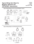
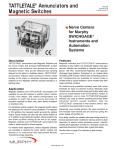
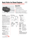
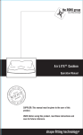
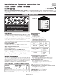
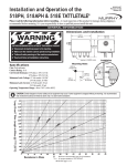
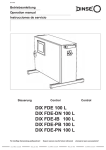
WS-93002N
Revised 04-06
Section 30
(00-02-0191)
Murphy W-Series Engine Panels
General Installation Instructions
Read the following information before installing. These installation instructions are typical for a variety of W-Series engine panels and may
not reflect the exact configuration for your panel assembly. It is assumed that the installer is familiar with engine operations and has basic
mechanical and electrical skills. If additional assistance is needed, please call your Murphy dealer or contact one of our offices at the numbers
listed on this instruction sheet. A visual inspection for any damage which may have occurred during shipping is recommended.
GENERAL INFORMATION
WARNING
BEFORE BEGINNING INSTALLATION OF THIS MURPHY PRODUCT
✔
✔
✔
✔
Disconnect all electrical power to the machine.
Make sure the machine cannot operate during installation.
Follow all safety warnings of the machine manufacturer.
Read and follow all installation instructions.
WD300-LV
Description
Generally, pressure and temperature Swichgage® contacts are wired to a
central nerve center called a Magnetic Switch or Tattletale® annunciator.
This nerve center is essentially a relay and, when signaled by a
Swichgage contact operation, it either makes or breaks a circuit to operate an alarm or engine shutdown device. Various nerve centers are used
depending upon the operation to be performed, the type of electrical
power available and the type of alarm or shutdown device used.
Typical wiring diagrams for the popular Tattletale annunciators and magnetic switches are included in this instructions. If a drawing of the specific
model number is enclosed, refer to that drawing for specific wiring.
CAUTION: Certain dangers to human safety and to equipment may occur if some equipment is stopped without pre-warning. It is recommended that
monitored functions be limited to alarm only or to alarm before shutdown.
INSTALLATION INFORMATION
Mounting the Panel
WARNING: Perform mounting operation with power source OFF.
Disable the engine so it cannot start. Remove the battery ground cable.
1. Select a suitable mounting location on or near the engine. The location
should provide easy access to the panel and provide unobstructed
viewing of the Swichgage instruments.
2. The mounting location should avoid shock and vibration to the extent
possible. Generally, a location low on the engine is preferred. Avoid
mounting on top of the engine if possible. Shockmounts are
suggested where possible to dampen shock and vibration.
IMPORTANT: Use of improper shockmounts can accelerate the shock
and vibration effects. Consult the factory if you are in doubt.
NOTE: If shockmounts are used, it is suggested that a separate ground
wire be attached to the panel assembly and to the engine. This assures
electrical continuity between the Swichgage contacts and the battery
ground across the shockmounts (see mounting detail below).
Connecting the Pressure Swichgage
1. Pressure tubing is generally not provided. Use of good quality flexible pressure tubing/hose and fittings is strongly suggested. Use at
least 3 / 16 in. (5 mm) I.D. tubing. If using copper or rigid
tubing, install at least 12 in. (305 mm) flexible hose from the pressure Swichgage instrument to the rigid tubing. This prevents damaging vibration from reaching the Swichgage instrument.
2. Connect the pressure tubing to the 1/8-27 NPT pressure port of the
pressure Swichgage instrument. Use of a non-hardening thread sealing compound is recommended although the thread is “dry seal”. Be
sure that thread sealant does not foul the pressure orifice.
NOTE: The orifice can be removed for cleaning.
3. Connect the pressure tubing to the pressure galley of the engine.
Generally this is at the oil filter housing. Use of non-hardening
thread sealant is recommended. Avoid droops or sink traps in
routing of the pressure line.
Installation Accessories
DETAIL
shockmount
panel
engine
nut and
washer
nut and
washer
electrical
ground jumper
panel
engine
frame
Tools and equipment needed:
®
● Thread sealant or Teflon tape.
● Straight edge screwdriver (medium).
● Wire stripping and terminal crimping tools.
● Electrical wire for use on power connections.
● Adjustable wrench or open end wrench set.
WS-93002N page 1 of 7
INSTALLATION INFORMATION continued
Connecting High Temperature
Swichgage instrument
LIQUID COOLED ENGINES:
1. Drain engine coolant to a level below the temperature sensing connection/plug. This connection is on the engine side of the thermostat
generally near the thermostat housing. Consult your engine manual.
2. Remove adapter nut from temperature sensing bulb and union nut.
3. Apply a non-hardening thread sealant to the adapter nut and screw
securely into the water jacket opening on the engine.
4. Route the temperature capillary away from hot surfaces such as
exhaust manifolds.
5. Place the sensing bulb into the adapter nut and observe that the sensing bulb does not “bottom” in the water jacket nor are there other
obstructions in the water jacket opening. Secure sensing bulb into
the adapter nut with the 5/8-18 union nut. See mounting detail below.
CAUTION: Do NOT cut or bend the temperature capillary at a
sharp angle. Excess capillary must be carefully coiled and
secured. The temperature sensing bulb must be immersed
directly into the water jacket flow to sense coolant temperature. Do NOT
install into a tee or other fitting. Use only Murphy adapter nuts.
6. Coil excess temperature capillary into a 2 in. (51 mm) diameter
minimum coil. Tie the coil to prevent excessive movement.
Sensing Bulb Mounting Detail
capillary
union
nut
adapter
nut
engine block
sensing
bulb
insertion
coolant
flow
Sensing
bulb
AIR COOLED ENGINES:
Temperature for air cooled engine can be measured in the cylinder head or
in the lubricating oil. Oil temperature will give a more uniform reading
than cylinder head since the oil circulates throughout the engine. Refer to
specific instructions supplied, if any, for your specific application.
1. Oil Temperature
a. The Swichgage sensing probe must be fully immersed in the oil
pan, oil filter housing, oil cooler, etc. depending on engine
model and configuration.
b. Observe all precautions for liquid cooled engines.
2. Cylinder Head Temperature
a. Generally the cylinder head must already have a hole drilled
and tapped for insertion of the temperature sensing probe.
b. If a hole is not provided in the cylinder head and no provision
is made to drill and tap one, it may be possible to install an
external bolt on heat sink such as the Murphy HS7.
c. Coat the temperature sensing probe with a high temperature
grease. A mixture of silicone and graphite flakes is recommended although grease alone can be used.
CAUTION: Do NOT apply too much grease. If grease is pushed out of
the hole when temperature probe is inserted, remove some grease.
d. Observe all precautions for liquid cooled engines.
Installing the Engine Stop Device or Alarm
Follow instructions provided with the stop device or alarm.
CAUTION: The Swichgage contacts are “pilot duty”. Generally a
nerve center/magnetic switch or relay is required between the
Swichgage contacts and the shutdown or alarm device. Failure to
use a nerve center/magnetic switch will result in contact failure in
the Swichgage and failure of the shutdown or alarm device to operate.
Electric Wiring
1. Disconnect the battery ground cable or otherwise disconnect
electric power from the engine and panel.
2. See the appropriate typical or specific wiring diagram for the nerve
center/magnetic switch in your panel.
3. Generally you will only be required to wire the battery or other electrical power to the nerve center/magnetic switch and the output circuit
from the nerve center/magnetic switch to the alarm or shutdown device.
4. Ammeters should be direct wired according to the wiring included
with this panel. Use minimum 10 AWG cable.
5. Be sure that the connected load(s) does not exceed the voltage and
current ratings of the nerve center/magnetic switch or Swichgage.
CAUTION: Never check for voltage by shorting a wire or terminal to
ground. This will ALWAYS damage the electrical components.
Placing Into Operation
1. Refill oil and coolant to proper levels.
2. Reconnect electrical power.
3. Service the engine as required by the engine manufacturer before
attempting to start the engine.
To Start the Engine
1. Fully depress the red or black push button of the nerve center/magnetic switch on the panel face. Hold in the button while cranking the
engine. This overrides the engine shutdown to allow starting. When
the oil pressure pointer moves away from the pointer contact (or
when pressure exceeds the preset low trip point) release the push
button. The engine should be operating. If the push button is red, it
should remain depressed. If the push button is black, it should
return to an extended position.
CAUTION: If the pressure Swichgage is equipped with a face mounted
lockout push button, be sure that pressure has been established and
that the lockout mechanism has disengaged. Failure to disengage will
prevent the Swichgage control from operating on low pressure.
2. Allow the engine to warm up and the thermostat to open. Slightly
loosen the 5/8-18 union nut on the temperature sensing bulb to allow
trapped air to escape from the cooling system. Retighten the nut.
WARNING: Perform this operation using appropriate protection.
Trapped air and coolant may cause skin burns.
3. Loosen the oil line fitting slightly at the pressure Swichgage to
allow trapped air to escape from the tubing. Retighten the fitting.
To Stop the Engine
1. Return the engine to idle speed and unload any driven equipment.
CAUTION: You should stop the engine in a normal manner.
Turn off the power switch, pull shutoff cable, etc. Do NOT use
the Swichgage control instrument as a normal shutoff.
2. DISTRIBUTOR IGNITION engine panels may have an
Emergency Stop Button, a start key switch or other power on/off
switch. Operate that switch or button. The nerve center/Magnetic
Switch will trip and open the ignition circuit to stop the engine.
3. DIESEL ENGINES may be equipped with “energized to RUN” or
“energized to STOP” devices. For “energized to RUN” devices such
as Murphy SV series fuel valves or RP-type solenoids, operation is
identical to above for distributor ignition engines. The “energized to
RUN” device is de-energized and the engine stops. For “energized
to STOP” devices the nerve center/magnetic switch applies battery
power to the stop device. Power is removed after a short time delay
depending on the specific nerve center/magnetic switch.
See instructions supplied with the shutdown or alarm device.
For normal stop, pull the manual stop cable.
WS-93002N page 2 of 7
Setting the SWICHGAGE® contacts
1. Face mounted contacts are set using a 1/16 in. hex wrench.
2. Some models such as 20PE, 20TE, etc. may not have field adjustment. Consult the factory if in doubt.
3. Observe the “normal operating” oil pressure and coolant temperature readings. Set the oil pressure Swichgage contact slightly below
the minimum reading observed or slightly above the minimum
pressure recommended by the engine manufacturer.
Testing the Swichgage Instruments
For face mounted contacts (20P, 20T, 20PW7, etc.):
1. With the engine running; use a 1/16 in. hex wrench to rotate the contact until it touches the gauge pointer. Do NOT force the contact
against the pointer. Engine should shut down and/or alarm should
operate. Reset the contact.
2. An alternative method of testing the
shutdown circuit is to place a coin
or other metal object between the
contact adjustment and the bezel.
NOTE: This method does NOT test
the actual contact pair. It does test the
circuit beyond the contact.
3. VERY IMPORTANT Each time you
start the engine, observe that the Swichgage instruments are indicating pressure or temperature, etc. Visual inspection and regular testing should be normal procedure to ensure proper operation and to
achieve maximum results from your Swichgage system.
WARNING: If the pressure Swichgage instrument has a
lockout push button on the face, a contact setting higher than the
factory setting will make the lockout device inoperative.
4. Set the temperature Swichgage contact slightly above the “normal
operating” temperature reading observed or slightly below the maximum temperature recommended by the engine manufacturer.
NOTE: More detailed instructions are contained in Installation Sheet
P-95033N for pressure Swichgage instruments and T-8446N for
Temperature Swichgage instruments.
TYPICAL WIRING DIAGRAM WITH 117PH MAGNETIC SWITCH
CAUTION: This wiring is typical for Murphy W-Series small engine panels. Items shown may or may not be included in your panel;
however, the circuit is typical of how the component will be wired if it is included. Refer to installation instructions for the specific
component if included. For off-panel items such as shutdown devices, see specific instructions supplied with the device.
Model 117PH
Tachometer
B+
117PH
Use for 12 or 24 VDC
SIG GRD
Other
Swichgage instruments
20P
Pressure
20T
Temperature
C
S
To Magnetic Sensor,
Alternator “Tach”
Terminal, or
Signal Generator
B
PB128S Stop Switch
+ _
Hourmeter
+ _
Voltmeter
Ammeter
Distributor
Ignition coil
+
+ _
Battery
ST BAT
IGN
Start
Switch
Fuel Valve
ACC
Energized
to Run
S
B
Starter
Rack Pull Solenoid
(RP2300 Series shown)
B+
Exciter
Alternator
WS-93002N page 3 of 7
_
TYPICAL WIRING WITH 518PH TATTLETALE CLOSED LOOP
CAUTION: This wiring is typical for Murphy W-Series small engine panels. Items shown may or may not be included in your panel;
however, the circuit is typical of how the component will be wired if it is included. Refer to installation instructions for the specific
component if included. For off-panel items such as shutdown devices, see specific instructions supplied with the device.
Tachometer
518PH WIRED CLOSED LOOP
MUST specify 12 or 24 VDC
B+
518PH
SIG GRD
R
Other
Swichgage instruments
20P-F
Pressure
20T-F
Temperature
G
NC
SW1
SW2 B
Hourmeter
+ _
To Magnetic Sensor,
Alternator “Tach”
Terminal, or
Signal Generator
Voltmeter
+ _
PB128S Stop Switch
To
From
Other Normally Closed Contacts
Ammeter
Distributor
+
+ _
Battery
Ignition coil
ST
IGN
Fuel Valve
Start
Switch
BAT
ACC
Energized
to Run
S
B
Starter
Energized to Run
Rack Pull Solenoid
(RP2300 Series shown)
B+
Exciter
Alternator
WS-93002N page 4 of 7
_
TYPICAL WIRING DIAGRAM WITH 518PH TATTLETALE JUMPERED
CAUTION: This wiring is typical for Murphy W-Series small engine panels. Items shown may or may not be included in your panel;
however, the circuit is typical of how the component will be wired if it is included. Refer to installation instructions for the specific
component if included. For off-panel items such as shutdown devices, see specific instructions supplied with the device.
Tachometer
518PH WIRED WITH JUMPER
Must specify 12 or 24 VDC
B+
518PH
SIG GRD
R
Other
Swichgage instruments
20P
Pressure
20T
Temperature
G
NC
SW1
SW2 B
Hourmeter
+ _
To Magnetic Sensor,
Alternator “Tach”
Terminal, or
Signal Generator
Jumper
Voltmeter
+ _
PB128S Stop Switch
Distributor
Ammeter
+
+ _
Battery
Ignition coil
ST
IGN
Fuel Valve
Start
Switch
BAT
ACC
Energized
to Run
S
B
Starter
Energized to Run
Rack Pull Solenoid
(RP2300 Series shown)
B+
Exciter
Alternator
WS-93002N page 5 of 7
_
TYPICAL WIRING DIAGRAM WITH 760A AND 761APH
CAUTION: This wiring is typical for Murphy W-Series small engine panels. Items shown may or may not be included in your panel;
however, the circuit is typical of how the component will be wired if it is included. Refer to installation instructions for the specific
component if included. For off-panel items such as shutdown devices, see specific instructions supplied with the device.
760A and 761APH
Tachometer
Must specify 12 or 24 VDC.
Specify positive or
negative ground.
30 second time delay
standard.
760A/761APH
B+
SIG GRD
TD
NOTE 1
Other
Swichgage instruments
20T
Temperature
20P
Pressure
G
NO
NC
S
B
Hourmeter
+ _
To Magnetic Senso
Alternator "Tach"
Terminal, or
Signal Generator
Voltmeter
+ _
PB128S Stop Switch
Ammeter
Distributor
+ _
Ignition coil
_
Battery
ST
IGN
Start
Switch
Fuel Valve
(Murphy's SV Series)
+
BAT
ACC
S
B
Starter
Energized
to Run
Energized to Run Rack Pull Solenoid
(Murphy's RP2300 Series shown)
B+
Exciter
Alternator
NOTE 1: With terminal “G” grounded, the time delay operates only on start; after the initial time delay,
the shut-down circuit is operated immediately when Swichgage contact operates.
With terminal “G” not grounded, the time delay operates both on start and stop.
WS-93002N page 6 of 7
TROUBLESHOOTING TIPS
Make sure the voltage and current requirements are within the W-Series ratings. Determine the polarity for
the application. Use appropriate wire size for voltage and current.
These instructions will assist in the correction of most problems which you may encounter with the panel. Before checking the list, first refer
to the wiring connections and operation procedures and make sure the panel is properly installed. If problems persist after making the
following checks, consult any Murphy facility.
SYMPTOM
PROBABLE CAUSE
CORRECTIVE ACTION
Engine will not start.
1. Blown fuse at magnetic switch.
2. Accidental ground to (S) or (C) terminals.
3. Overload circuit due to accessories.
4. Open circuit in 518PH wiring.
1. Replace fuse.
2. Check for ground and correct.
3. Re-route accessory circuits.
4. Repair circuit.
Pointer burned in two.
Overload of pointer contact due to exces
sive load or short circuit.
False shutdown.
1. Wire from Swichgage instrument is
grounded or shorted to contact.
2. Closed Loop circuit has intermittent
open or short.
3. Excessive shock or vibration causes
magnetic switch to trip.
4. Lack of coolant around temperature sensing
bulb causes “hot spot”.
5. Temperature capillary routed too close to
exhaust manifold.
SWICHGAGE® contact closes
but does not trip the magnetic
switch to stop the engine.
Inaccurate readings.
Fuel shutoff valve used on diesel engine.
Magnetic Switch trips but
engine does not stop.
1. Remove ground or short.
2. Check all wiring and repair.
3. Isolate panel from shock/vibration.
4. Check coolant level; loosen the union nut to allow trapped
air to escape.
5. Reroute temperature capillary.
Locate open circuit and repair; turn the contact adjustment
against the pointer causing them to “wipe” against each
other. Be sure magneto is providing power to primary
terminal post. CD type magnetic switch used with magneto.
Incomplete circuit.
1. Pressure orifice plugged with thread sealant.
2. Temperature capillary rerouted too close to
exhaust manifold.
3. Broken or crushed temperature capillary.
Engine does not stop
immediately.
Remove or reduce load; remove short circuit and replace
Swichgage instrument.
Feedback from alternator.
1. Remove and clean pressure orifice.
2. Reroute capillary.
3. Replace Swichgage instrument.
Be sure all fittings are air tight; use check valve in bypass
line; use rack puller in place fuel valve.
Install diode in excitation circuit.
Warranty
A limited warranty on materials and workmanship is given with this FW Murphy product.
A copy of the warranty may be viewed or printed by going to www.fwmurphy.com/support/warranty.htm
www.fwmurphy.com
918.317.4100 Email: [email protected]
In order to consistently bring you the highest quality, full featured products, we reserve the right to change our
specifications and designs at any time. MURPHY, the Murphy logo, and Swichgage® are registered and/or common
law trademarks of Murphy Industries, Inc. This document, including textual matter and illustrations, is copyright
protected by Murphy Industries, Inc., with all rights reserved. (c) 2006 Murphy Industries, Inc.
In order to consistently bring you the highest quality, full featured products, we reserve the right to change our specifications and designs at any time.
WS-93002N page 7 of 7