1
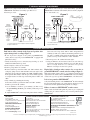
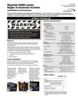
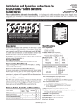
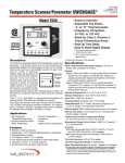
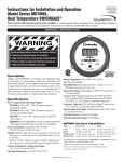
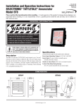
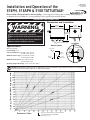
00-02-0187
Revised 10-06
Section 25
Installation and Operation of the
518PH, 518APH & 518E TATTLETALE®
Please read the following information before installing. A visual inspection of this product for damage during shipping is
recommended before mounting. It is your responsibility to have a qualified person install this unit.
GENERAL INFORMATION
Dimensions and Installation
2-5/8 in.
(67 mm)
WARNING
2-5/16 in.
(59 mm)
BEFORE BEGINNING INSTALLATION OF THIS MURPHY PRODUCT
✔
✔
✔
✔
2-15/32 in.
(63 mm)
Disconnect all electrical power to the machine.
Make sure the machine cannot operate during installation.
Follow all safety warnings of the machine manufacturer.
Read and follow all installation instructions.
Applies to 518APH model.
Specifications
Case: Polycarbonate
Contact Rating: 10 A
Coil Circuit Resistance: 339 ohms ± 10% 12 Volt
678 ohms ± 10% 24 Volt
Minimum Latch Voltage: 12 Volt model: 10 VDC
24 Volt model: 20 VDC
Minimum Latch Current: 12 Volt model: 30 mA
24 Volt model: 30 mA
Operating Temperature Range: -40 to 176°F (-40 to 80°C)
Installation
Mounting Holes
25/64 in.
(10 mm) dia
Instruction
Plate
13/16 in.
(21 mm)
9/16 in.
(14 mm)
Panel
1/4 in.
(6 mm) dia
TATTLETALE®
Hex
Nut
Lockwasher
CAUTION: Certain dangers to human safety and to equipment may occur if some equipment is stopped without pre-warning. It is recommended
that monitored functions be limited to alarm only or to alarm before shutdown.
“Loop Circuit” Wire Length in Miles @ 77°F (25°C)
Resistance in Ohms
Maximum recommended Loop Circuit resistance
for proper operation of TATTLETALE®.
00-02-0187 page 1 of 2
TYPICAL WIRING DIAGRAMS
Figure 1 shows a jumper installed between “SW1 and “SW2”.
SWICHGAGE® instruments are normally open. This is not a
Closed Loop™ circuit.
Figure 2 shows a Closed Loop™ circuit with normally open Murphy
SWICHGAGE® instruments and Normally Closed switches (alignment
and “V” belt switches, etc.).
Figure 1
Figure 2
518PH / 518APH / 518E
518PH / 518APH / 518E
Ammeter
R
“Energized”
To Shutdown
Solenoid Operator*
G NO
NC
SW1
**
Ammeter
R
SW2 B
“Energized”
To Shutdown
Solenoid Operator*
14 Amp
In-Line Fuse*
G NO
NC
SW1
SW2 B
**
14 Amp
In-Line Fuse*
Ignition
Switch
Ignition
Switch
Normally Open
SWICHGAGE® Instruments
Normally Open
SWICHGAGE® Instruments
“De-energized”
To Shutdown
Fuel Valve
or
Solenoid
Operator
“De-energized”
To Shutdown
Fuel Valve
Battery
“De-energized”
To Shutdown
Ignition Coil
Normally
Closed
Switches
“De-energized”
To Shutdown
Ignition Coil
* In-Line Fuse should be removed on
** Applies to 518APH model.
* In-Line Fuse should be removed on “energized” to shutdown configurations.
** Applies to 518APH model.
Battery
“energized” to shutdown configurations.
TROUBLESHOOTING
Push button will not remain in the depressed position after
engine startup (wired according to Figure 2).
• Be sure oil pressure is adequate to raise pointer past SWICHGAGE®
contact. (Not necessary if oil pressure SWICHGAGE® is equipped with
push button lockout.)
• Visually check wiring for loose connections, frayed wiring, etc. on all
terminals and within switch loop circuit.
• Check 14 amp fuse connected to “B” terminal.
• Check for good ground on “G” terminal.
• Disconnect switch loop circuit from “SW1” and “SW2” terminals. Place
a temporary jumper between SW1 and SW2 and restart engine. If the
push button stays in with engine running, the 518PH, 518APH & 518E is
not the problem. This indicates either an open circuit, unwanted ground,
or too high resistance in switch loop circuit wiring between “SW1” and
“SW2”.
• Verify continuity by performing the following:
1. Disconnect switch loop circuit from “SW1” and “SW2” terminals.
2. Remove power from “B” terminal.
3. Use an ohmmeter to check for “good continuity” (25 ohms or less)
through switch loop circuit. If good continuity is indicated, proceed
to Step 4.
4. Adjust SWICHGAGE® contact away from pointer. Check continuity
between one end of loop circuit, “SW1 or “SW2” and ground. Good
continuity (25 ohms or less) indicates an unwanted ground in loop circuit such as a terminal rotating against the mounting panel. Remove
ground, restore loop circuit connections to “SW1” and “SW2”.
5. Reconnect power to “B” terminal and restart engine.
6. Using an ohmmeter, check resistance between one end of the loop
circuit to the other. Resistance should not exceed 25 ohms. If resistance is too high, check for loose connections in loop circuit.
Otherwise select larger size wire for loop circuit.
Engine fails to shutdown when contacts close on one-wire to
ground SWICHGAGE® controls (wired according to Figure 1).
With engine running, jumper “SW1” to “G” terminal. If switch trips and
engine shuts down, trouble could be SWICHGAGE® contacts not making
contact, lack of good case ground on SWICHGAGE®, or broken/cut wire.
Lack of case ground on SWICHGAGE®.
Verify that mounting bracket on the SWICHGAGE® has broken through
the panel paint and has made good contact with bare metal. If good contact has not been made, tighten mounting stud nuts accordingly.
Failure of contacts on SWICHGAGE® to make contact.
Adjust contacts back and forth against the pointer to give a wiping and
cleaning action on contacts. If this does not correct the problem, replace
SWICHGAGE®.
FW MURPHY
CONTROL SYSTEMS & SERVICES DIVISION
COMPUTRONIC CONTROLS, LTD
P.O. Box 470248
Tulsa, Oklahoma 74147 USA
+1.918.317.4100 Fax: +1.918.317.4266
E-mail: [email protected]
P.O. Box 1819
Rosenberg, Texas 77471 USA
Phone: 281.633.4500 Fax: 281.633.4588
E-mail: [email protected]
Web site: www.fwmurphy.com
41 - 43 Railway Terrace Nechells
Birmingham B7 5NG UK
Phone: +44 121 327 8500 Fax: +44 121 327 8501
E-mail: [email protected]
Web site: www.computroniccontrols.com
FRANK W. MURPHY, LTD
FW MURPHY INSTRUMENTS (HANGZHOU) CO. LTD
Church Rd Laverstock
Salisbury SP1 1QZ UK
Phone: +44 1722 410055 Fax: +44 1722 410088
E-mail: [email protected]
Web site: www.fwmurphy.co.uk
77 23rd Street
Hangzhou Economic & Technological Development Area
Hangzhou, Zhejiang, 310018, China
Phone: +86 571 8788 6060 Fax: +86 571 8684 8878
INDUSTRIAL PANEL DIVISION
Fax: 918.317.4124
E-mail: [email protected]
MURPHY POWER IGNITION
Web site: www.murphy-pi.com
www.fwmurphy.com
Printed in U.S.A.
In order to consistently bring you the highest quality, full featured products, we reserve the right to change our specifications and designs at any time.
00-02-0187 page 2 of 2