1
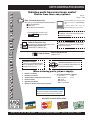
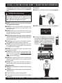
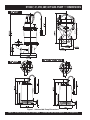
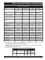
OPERATION AND PARTS MANUAL
MODELS:
ST2037
ST2047
ST2047B
ST2038P
ST2040T
SUBMERSIBLE PUMPS
Revision #3 (06/15/10)
To find the latest revision of this
publication, visit our website at:
www.multiquip.com
THIS MANUAL MUST ACCOMPANY THE EQUIPMENT AT ALL TIMES.
ST2037, 47, 47B, 40T, 38P SERIES SUB. PUMPS — TABLE OF CONTENTS
Multiquip ST2037, ST2047,
ST2047B ST2038P and
ST2040T Submersible
Pumps
Table Of Contents ..................................................... 2
Parts Ordering Procedures ....................................... 3
Here's How to Get Help ............................................ 4
Safety Message Alert Symbols ................................. 5
Rules For Safe Operation ...................................... 6-7
Dimensions ............................................................... 8
Specifications (Pump/Control Box) ...........................9
General Information ................................................10
Components............................................................11
Float Switches .........................................................12
Float Switch (Piggy-Back) .......................................13
Float Switch (Control Box) ......................................14
Operation ................................................................15
Control Box Installation ..................................... 16-17
Clean-up .................................................................18
Maintenance ...........................................................19
Troubleshooting ......................................................20
Performance Curves ...............................................21
Pump Wiring Diagram .............................................22
Explanation Of Codes In Remarks Column ............24
Suggested Spare Parts ...........................................25
Submersible Pump
Component Drawings
ST2037,ST2047, 2047B Pump Assembly ......... 26-27
ST2040T Pump Assembly ................................. 28-29
ST2038P Pump Assembly .................................. 30-31
Terms and Condition of Sale — Parts .....................32
NOTE
As a continuing effort to update
our parts book, contact the
MULTIQUIP literature department
for the latest revision of your
"Operation and Parts Manual"
PAGE 2 — ST2037,47, 47B, 38P, 40T SUB. PUMPS — OPERATION AND PARTS MANUAL — REV. #3 (06/15/10)
www.multiquip.com
PARTS ORDERING PROCEDURES
Ordering parts has never been easier!
Choose from three easy options:
Order via Internet (Dealers Only):
Best Deal!
Effective:
January 1st, 2006
If you have an MQ Account, to obtain a Username
and Password, E-mail us at: parts@multiquip.
com.
Order parts on-line using Multiquip’s SmartEquip website!
N View Parts Diagrams
N Order Parts
N Print Specification Information
To obtain an MQ Account, contact your
District Sales Manager for more information.
Use the internet and qualify for a 5% Discount
on Standard orders for all orders which include
complete part numbers.*
Goto www.multiquip.com and click on
Order Parts to log in and save!
Note: Discounts Are Subject To Change
Order via Fax (Dealers Only):
All customers are welcome to order parts via Fax.
Domestic (US) Customers dial:
1-800-6-PARTS-7 (800-672-7877)
Fax your order in and qualify for a 2% Discount
on Standard orders for all orders which include
complete part numbers.*
Note: Discounts Are Subject To Change
Order via Phone: Domestic (US) Dealers Call:
1-800-427-1244
Non-Dealer Customers:
Contact your local Multiquip Dealer for
parts or call 800-427-1244 for help in
locating a dealer near you.
International Customers should contact
their local Multiquip Representatives for
Parts Ordering information.
When ordering parts, please supply:
R
R
R
R
R
R
Dealer Account Number
Dealer Name and Address
Shipping Address (if different than billing address)
Return Fax Number
Applicable Model Number
Quantity, Part Number and Description of Each Part
R
Specify Preferred Method of Shipment:
UPS/Fed Ex
DHL
N Priority One
Truck N Ground
N Next Day
N Second/Third Day
NOTICE
All orders are treated as Standard Orders and will
ship the same day if received prior to 3PM PST.
WE ACCEPT ALL MAJOR CREDIT CARDS!
ST2037,47, 47B, 38P, 40T SUB. PUMPS — OPERATION AND PARTS MANUAL — REV. #3 (06/15/10) — PAGE 3
NOTE PAGE
PAGE 4 — ST2037,47, 47B, 38P, 40T SUB. PUMPS — OPERATION AND PARTS MANUAL — REV. #3 (06/15/10)
ST2037, 47, 47B, 38P, 40T SUB. PUMP— SAFETY MESSAGE ALERT SYMBOLS
FOR YOUR SAFETY AND THE SAFETY OF OTHERS!
Safety precautions should be followed at all times when
operating this equipment. Failure to read and understand the
Safety Messages and Operating Instructions could result in
injury to yourself and others.
NOTE
This Owner's Manual has been
developed to provide complete
instructions for the safe and efficient
operation of the Multiquip Model s
ST2037, ST2047, ST2047B,
ST2038P,
and
ST2040T
Submersible Pumps. Before using
these pumps, ensure that the
operating individual has read and
understands all instructions in
HAZARD SYMBOLS
Rotating Parts
NEVER operate equipment with covers,
or guards removed. Keep fingers, hands,
hair and clothing away from all moving
parts to prevent injury.
Accidental Starting
ALWAYS place the power source circuit
breaker or ON/OFF switch in the OFF
position, when the pump is not in use.
this manual.
SAFETY MESSAGE ALERT SYMBOLS
The three (3) Safety Messages shown below will inform you
about potential hazards that could injure you or others. The
Safety Messages specifically address the level of exposure to
the operator, and are preceded by one of three words: DANGER,
WARNING, or CAUTION.
Sight and Hearing hazard
DANGER
ALWAYS wear approved eye and
hearing protection, if required.
You WILL be KILLED or SERIOUSLY injured if you DO
NOT follow directions.
Respiratory Hazard
WARNING
You CAN be KILLED or SERIOUSLY injured if you DO
NOT follow directions.
ALWAYS wear approved respiratory
protection, if required.
CAUTION
CAUTION
You CAN be INJURED if you DO NOT follow directions.
Potential hazards associated with the ST2037, ST2047,
ST2047B, ST2038P, and ST2040T submersible pumps
operation will be referenced with Hazard Symbols which appear
throughout this manual, and will be referenced in conjunction
with Safety Message Alert Symbols.
Equipment Damage Messages
Other important messages are provided throughout this manual
to help prevent damage to your submersible pump, other property,
or the surrounding environment.
NOTE
This submersible pump, other
property, or the surrounding
environment could be damaged if
you do not follow instructions.
ST2037,47, 47B, 38P, 40T SUB. PUMPS — OPERATION AND PARTS MANUAL — REV. #3 (06/15/10) — PAGE 5
ST2037, 47, 47B, 38P, 40T SUB. PUMP — RULES FOR SAFE OPERATION
CAUTION
Failure to follow instructions in this manual may lead to serious
injury or even death! This equipment is to be operated by
trained and qualified personnel only! This equipment is for
industrial use only.
The following safety guidelines should always be used when
operating the ST2037, ST2047, ST2047B, ST2038P, and
ST2040T Submersible Pump:
■ NEVER use gas piping as an electrical ground.
■ DO NOT place hands or fingers inside pump when pump is
running.
■ ALWAYS make certain that the voltage supplied to the pump
is correct. Always read the pump's nameplate to determine
what the power requirements are. The ST2037, ST2047,
ST2038P, and ST2040T submersible pumps require 115
VAC, 60 Hz (single-phase) for normal operation.
■ DO NOT restrict the flow of the discharge hose as it may
cause overheating.
GENERAL SAFETY
■ Be careful of discharge whipping under pressure.
■ DO NOT operate or service this equipment
before reading this entire manual.
■ Make sure pump installation is accordance with national
and local electrical codes.
■ This equipment should not be operated by
persons under 18 years of age.
■ NEVER operate this equipment without proper protective
clothing, shatterproof glasses, steel-toed boots and other
protective devices required by the job.
■ ALWAYS have a qualified electrician perform the pump
wiring installation.
■ ALWAYS mount the control box in a vertical position
protected from the elements.
■ NEVER handle pump's AC power cord with wet hands.
■ NEVER let an extension cord or plug connection lay in water.
■ NEVER stand in water while AC power cord is connected
to a power source.
■ NEVER operate this equipment when not feeling
well due to fatigue, illness or taking medicine.
■ NEVER operate this equipment under the
influence or drugs or alcohol.
■ NEVER use a pump with a defective, frayed power cord.
Check the power cord on the pump for cuts in the insulation.
■ NEVER use a extension cord that is frayed or damaged
where the insulation has been cut.
■ ALWAYS make certain that proper extension cord has been
selected for the job See Table 4.
■ NEVER attempt to use the power cord as a lifting or lowering
device for the submersible pump.
■ NEVER use accessories or attachments, which are not
recommended by Multiquip for this equipment. Damage to the
equipment and/or injury to user may result.
■ Manufacture does not assume responsibility for any accident
due to equipment modifications.
■ Whenever necessary, replace nameplate, operation and safety
decals when they become difficult read.
■ ALWAYS check the machine for loosened threads or bolts
before starting.
■ NEVER operate the submersible pump in an explosive
atmosphere or near combustible materials. An explosion or fire
could result causing severe bodily harm or even death.
■ ALWAYS make sure submersible pump is grounded.
■ When raising or lowering of the submersible pump is
required, always attach an adequate rope or lifting device
to the correct lifting point (handle) on the pump.
■ ALWAYS place the pump in an upright position on a platform
before using. The platform will prevent the pump from
burrowing itself on soft sand or mud.
■ NEVER operate pump on its side.
■ DO NOT allow the pump to freeze in water.
■ NEVER leave an open pump chamber unattended.
■ The electrical voltage required to operate the pump can
cause severe injury or even death through physical contact
with live circuits. ALWAYS disconnect the electrical power
from the pump before performing maintenance on the pump.
■ ALWAYS make sure that electrical circuits are properly
grounded per the National Electrical Code (NEC) and
PAGE 6 — ST2037,47, 47B, 38P, 40T SUB. PUMPS — OPERATION AND PARTS MANUAL — REV. #3 (06/15/10)
ST2037, 47, 47B, 38P, 40T SUB. PUMP — RULES FOR SAFE OPERATION
local codes before operating pump. Severe injury or death
by electrocution can result from operating an ungrounded
pump.
. Emergencies
■ ALWAYS know the location of the nearest fire extinguisher.
WARNING- Risk of Electric Shock
This pump is supplied with a grounding conductor and
grounding-type attachment plug. To reduce the risk of
electric shock, be certain that it is connected only to a
properly grounded, grounding-type receptacle.
■ NEVER use this pump to remove water from a swimming pool
when people are in the water.
■ ALWAYS be sure the operator is familiar with proper safety
precautions and operations techniques before using
submersible pump.
■ ALWAYS check pump oil level only when pump is cool.
Expansion due to heat may cause hot! oil to spray from the oil
plug when the oil plug is removed.
■ DO NOT attempt to thaw-out a frozen pump by using a torch
or other source of flame. Application of heat in this manner
may heat the oil in the seal cavity above the critical point,
causing pump damage.
■ DO NOT pump water greater than 104 degrees Fahrenheit.
Also DO NOT pump liquids containing acid or alkali.
■ ALWAYS check strainer before pumping. Make sure strainer
is not clogged. Remove any large objects, dirt or debris from
the strainer to prevent clogging.
■ ALWAYS know the location of the nearest and first aid kit.
■ In emergencies always know the location of the
nearest phone or keep a phone on the job site.
Also know the phone numbers of the nearest
ambulance, doctor and fire department. This
information will be invaluable in the case of an
emergency.
■ ALWAYS use a large basket strainer when pumping water
that contain large debris.
■ ALWAYS flush pump after use when pumping water
concentrated with heavy debris. Flush with clean fresh
water. It is very important to always flush the pump before
turning it off to prevent clogging.
■ ALWAYS store equipment properly when it is not being used.
Equipment should be stored in a clean, dry location out of the
reach of children.
■ ALWAYS read, understand, and follow procedures in
Operator’s Manual before attempting to operate equipment.
Maintenance Safety
■ NEVER lubricate components or attempt service on a running
machine.
■ ALWAYS allow the machine a proper amount of time to cool
before servicing.
■ Keep the machinery in proper running condition.
■ Fix damage to the machine immediately and always replace
broken parts.
ST2037,47, 47B, 38P, 40T SUB. PUMPS — OPERATION AND PARTS MANUAL — REV. #3 (06/15/10) — PAGE 7
ST2037, 47, 47B, 38P, 40T SUB. PUMP — DIMENSIONS
Figure 1. Submersible Pump Dimensions
PAGE 8 — ST2037,47, 47B, 38P, 40T SUB. PUMPS — OPERATION AND PARTS MANUAL — REV. #3 (06/15/10)
ST2037, 47, 47B, 38P, 40T SUB. PUMP — SPECIFICATIONS
TABLE 1. SPECIFICATIONS
Model
ST-2037
ST-2047 / ST-2047B
Type
Centrifugal
Submersible Pump
Centrifugal
Submersible Pump
Nitorile Rubber over
Steel
Impeller
ST-2038P
ST-2040T
Centrifugal
Submersible Trash
Submersible Pump
Pump
Nitorile Rubber over Nitorile Rubber
Steel
over Steel
Nitorile Rubber
over Steel
Suction & Discharge Size
2.00 in. (50 mm)
2.00 in. (50 mm)
2.00 in. (50 mm)
2.00 in. (50 mm)
Maximum Pumping Capacity
73 gallons/minute
(272 liters/minute)
87 gallons/minute
(322 liters/minute)
60 gallons/minute
(227 liters/minute)
79 gallons/minute
(299 liters/minute)
Max Head
37 ft. (10.6 meters)
47 ft (13.9 meters)
38 ft (11 meters)
40 ft. (11.4
meters)
1 HP (0.75 kw)
1 HP (0.75 kw)
1 HP (0.75 kw)
1 HP (0.75 kw)
Voltage Phase
1Ø 115V
1Ø 115 V / 1Ø 230V
1Ø 115V
1Ø 120V
Star ting Amps
25
25 / 12.5
25
25
Running Amps
6.9
9.8 / 4.9
6.8
6.8
See Note 3
See Note 3
See Note 3
See Note 3
YES
YES
YES
YES
CCW (Note 1)
CCW (Note 1)
CCW (Note 1)
CCW (Note 1)
120 cc. (Note 2)
120 cc. (Note 2)
120 cc. (Note 2)
133 cc. (Note 2)
Monthly (300 hrs.)
Monthly (300 hrs.)
Monthly (300 hrs.)
Monthly (300 hrs.)
3390 +/- 30
3250 +/- 30
3400 +/- 30
3390 +/- 30
25 FT. (7.6 m.)
50 FT. (15.2 m.)
25 FT. (7.6 m.)
25 FT. (7.6 m.)
31 lb (14 kg)
33 lb (15 kg)
31 lb (14 kg)
34 lb (15.4 kg)
Power
Control Box Required
Thermal Overlaod Protection
Rotation
Mechanical Seal Oil Capacity
Check Frequency
RPM (Speed)
Power Cable Length
Dry Net weight
1.
Motor Rotation – Upon start-up, the pump "kicks" in the opposite direction of motor rotation. The correct rotation is
counterclockwise (CCW) as viewed from the impeller end of the pump.
2.
Mechanical Seal Oil – Use a good grade 10 weight non-detergent hydraulic oil (i.e. Shell Turbo 32 or equivalent). Fill oil cavity
75% to 85% full (allow air space for expansion).
3.
Control Box - Control box (Table 2) may be required for certain pumping applications.
Table 2. Control Box Specifications
Model No.
VoltageType
UL/CSA
Listed
CB3
115 VAC, 60 Hz SinglePhase
YES
Thermal
Float
Overload
Switch
Protection Capability
YES
YES
ST2037,47, 47B, 38P, 40T SUB. PUMPS — OPERATION AND PARTS MANUAL — REV. #3 (06/15/10) — PAGE 9
ST2037, 47, 47B, 38P, 40T SUB. PUMP — GENERAL INFORMATION
Introduction
The Multiquip Model ST2037, ST2047, ST2047B, ST2038P, and
ST2040T submersible pumps are designed to pump water and
is used for the draining (de-watering) of swimming pools, well
casings construction sites, cofferdams, manholes, transformer
vaults and excavations.
A Nitorile rubber over steel impeller is attached to the output
shaft of a 1HP electric motor which provides adequate power for
general purpose pumping. This submersible pump is supplied
complete with an electric power cable, and a discharge port
located at the top of the pump which accepts a 2-inch hose.
This pump is ideal for portability because of its light weight and
carrying handle. For reliability and long life, a mechanical seal
provides shaft sealing, with an oil chamber separating the pump
section from the motor.
The pump when in use, should be installed as free standing
(upright position) on its strainer base. A 2-inch discharge hose
(not supplied) should be connected to the discharge port located
on top of the pump. The discharge hose should be adequately
supported to avoid stress on the pump.
For maximum water flow, the discharge hose should be kept as
short as possible, and with minimum elevation above the pump.
Remember as the length and/or height of the discharge hose is
increased, the flow of water will be reduced. Also any reduction
in the hose size, and any fittings such as valves or outlet nozzles,
will restrict the water flow.
To avoid back-siphonage when the pump is switched off, ensure
that the end of the discharge hose is installed above the water
level at the final discharge point.
When the pump is switched off, the water remaining in the hose
will run back through the pump. This can be avoided by placing
a non-return valve in the hose nearest the pump.
NEVER use this submersible pump to pump flammable liquids
or operate in a explosive or flammable environment.
Avoid using this pump in conditions where mud, grit, silt or other
debris are present. These conditions could cause blockage and
cause excessive pump wear.
DO NOT install the pump directly into an area where there is a
heavy buildup of mud, grit, silt or debris. If this condition is present,
install the pump on a platform before operating.
This pump must always be positioned on a platform in an upright
position. NEVER operate the pump by a suspended rope. To
prevent large solids from entering the pump, install a wire mesh
screen or similar barrier around the pump.
If the pump was used to pump water containing mud, silt, use
clean water to flush out the pump after each use.
DO NOT allow the pump to run dry, as this will damage the
pump. During maintenance, dry running is permissible but only
for a few seconds.
NEVER lift the pump by its electrical power cord. ALWAYS lift
the pump by its carrying handle or attach a rope to the carrying
handle.
A pump fully submerged pump in liquid will not freeze, unless
the liquid freezes. DO NOT allow a partially submerged pump to
freeze. The expansion of water freezing in the volute may crack
the pump, causing expensive repairs. If there is any danger of
the pump being subjected to freezing temperatures, Lift the pump
from water and allow it to drain thoroughly.
If the pump jams or the pump rotor locks for any reason,
disconnect the pump from the power source immediately.
Allowing the pump motor to cycle ON and OFF under an overload
condition can burn out the motor.
When replacement of nuts and bolts is required, use only
recommended parts as referenced in the parts section of this
manual. This pump uses metric threads. DO NOT use English
measurement threads.
Control Box Installation Warnings
DANGER
When installing the CB3 control box, the
possibility exists of electrical shock ,
electrocution and possibly death! NEVER have
untrained personnel perform the installation.
ALWAYS have qualified service personnel (licensed
electrician) perform the installation.
WARNING
Explosion or Fire Hazard exists if this
pump is used with flammable liquids. DO
NOT use this pump with flammable
liquids. DO NOT install this pump in
hazardous locations as defined by the National Electrical
Code, ANSI/NFPA 70.
Failure to follow the above referenced precautions could result
in serious injury or death! Replace pump cord immediately if
cord becomes damaged or severed. This pump must be installed
in accordance with National Electric Code ANSI/NFPA 70 so as
to prevent moisture from entering or accumulating with the boxes,
conduit bodies fittings, float housing or cable.
PAGE 10 — ST2037,47, 47B, 38P, 40T SUB. PUMPS — OPERATION AND PARTS MANUAL — REV. #3 (06/15/10)
ST2037, 47, 47B,38P, 40T SUB. PUMP — COMPONENTS
ST2037, ST2047, ST2047B ST2038P
ST2040T
Figure 2. Submersible Pump Components
Figures 2 shows the location of the basic components, for the
ST2037, ST2047, ST2047B, ST2038P, and ST2040T
submersible pumps. Listed below is a brief explanation of each
component.
1.
2.
3.
4.
5.
6.
Carrying Handle – Always carry the submersible pump
by its handle. NEVER! carry the pump by its power cord.
Carrying or lifting the pump by the power cord, will cause
undue stress on the cord, and ultimately the cord will
become dislodged from the pump.
7.
Volute/Impeller – Impellers are constructed of Nitorile
Rubber to minimizes wear and prolong service life.
Thermal Overload Protection – This pump is equipped
with a thermal overload protection device that will shut down
the motor in the event of high operating temperatures. The
motor will automatically restart once the temperature returns
to an acceptable operating temperature.
8.
Electric Motor – These submersible pumps utilize a 60
Hz, single-phase, 115 VAC, 1 HP electric motor. Consult
with a licensed electrician before connecting motor to a
power source. Observe all city and local safety codes.
Mechanical Seal Oil – This oil filled seal provides
lubrication when running the pump dry. NEVER! run the
pump dry. Running the pump dry will cause severe damage
to the pump.
9.
Mechanical Seal Oil Plug – Remove this plug to check
and add hydraulic oil (Shell 32 or equivalent) to the oil
cavity. This oil protects the mechanical seal. Oil cavity should
be full enough to cover seal spring.
Strainer Base – This strainer base is made of electrocating
steel which is resistant to hardware corrosion. DO NOT
pump large objects or debris with this pump. This pump is
for pumping water only. For de-watering purposes, always
place the strainer base on a platform.
Discharge Port – Connect a 2-inch hose to this port.
Remember to adequately support the discharge hose to
avoid stress on the pump.
AC Power Cable – This unit is supplied with a 25 ft. (7.6
meters) or 50 ft. (15.2 meters) AC power cable. Always
check the cable for signs of wear. NEVER! use a defective
power cable. Replace the cable immediately if the cable is
worn or defective.
ST2037,47, 47B, 38P, 40T SUB. PUMPS — OPERATION AND PARTS MANUAL — REV. #3 (06/15/10) — PAGE 11
ST2037, 47, 47B, 38P, 40T SUB. PUMP — FLOAT SWITCHES
Float Switch Theory
Design Features
Mercury monitoring is a mercury-switch actuated, liquid level
control that has proven to be more economical and longer lasting
than other types of liquid-level control systems, easily replacing
and improving upon diaphragm switches, air bubble systems
and electromechanical switches most often relied upon in the
past.
Constructed of rigid, durable ABS polymer ultrasonically welded.
The all-steel mercury switch is held by positioning pins. Interior
is filled with cell foam.
How It Works
There is a tilt-sensitive mercury switch hermetically sealed within
each float. As the liquid level (water) rises or falls, the float changes
its angle until the mercury switch makes (close, Figure 4) or
breaks (open Figure 5) the circuit. Maximum pumping range is
120 degrees. See Figure 3 below.
■ Suitable for most liquid environments.
■ Hermetically sealed.
■ Thick-walled non-corrosive PVC plastic enclosure.
■ Pressure tested to 60 ft. (18.2 meters).
■ Mercury switch reliability, proven to 500,000 cycles.
■ Standard SJO, 16-gauge, 2 conductor cord (20 ft./6.09 m).
Figure 4. Float Switch (Closed)
Figure 3. Pumping Range (Float Switch)
Pumping Range
The pumping range of the pump is determined by the float switch
tether cord. Use Table 3 as guide line to determine your required
pumping range. Pumping ranges are based on non-turbulent
conditions. Range may vary due to water temperature and cord
shape. Please note as the tether length increases, so does the
variance of the pumping range.
Figure 5. Float Switch (Open)
Table 3. Pumping Range
Tether Length
2 in.
5.08 cm.
4 in.
6 in.
8 in.
10.16 cm. 15.24 cm. 20.32 cm.
Pumping Range
6 in.
15.24 cm.
10 in.
25.4 cm.
10 in.
25.4 cm.
14 in.
16 in.
12 in.
30.48 cm. 35.56 cm. 40.64 cm.
14 in.
18 in.
22 in.
27 in.
3 1 in .
35.56 cm. 45.72 cm. 55.88 cm. 68.58 cm. 78.74 cm.
35 in.
88.9 cm.
PAGE 12 — ST2037,47, 47B, 38P, 40T SUB. PUMPS — OPERATION AND PARTS MANUAL — REV. #3 (06/15/10)
ST2037, 47, 47B, 38P, 40T SUB. PUMP — FLOAT SWITCH (PIGGY-BACK)
Float Switch
Single or dual control float switches (Figure 6) can be used for the unattended operation of the submersible pump. When using the
piggy-back power configuration (plug), the pumps DO NOT require the use of a control box. In this configuration (piggy-back), the
SW-1 (single float switch) or SW-2 (dual float switch) are required. The illustration below is an example of a single float switch application.
Mounting The Float Switch
1.
Determine the required cord tether length as shown in
Figure 6 and Table 3.
2.
Place the cord into the clamp as shown in Figure 6.
3.
Secure the clamp to the discharge hose as shown in Figure
5. DO NOT install cord under hose clamp.
4.
Using a screwdriver, tighten the hose clamp. DO NOT overtighten. Make sure the float cord is not allowed to touch the
excess hose clamp band during operation.
NOTE
Figure 6 shows a single float switch
application. For dual float switch
capability use a Model SW-2 mercury
type float switch .
Figure 6. Single Float Switch
Application Diagram
ST2037,47, 47B, 38P, 40T SUB. PUMPS — OPERATION AND PARTS MANUAL — REV. #3 (06/15/10) — PAGE 13
ST2037, 47, 47B, 38P, 40T SUB. PUMP — FLOAT SWITCH (CONTROL BOX)
Control Box (CB3)
For special remote pumping applications of the submersible pump, a control box (Model CB3) may be required. This water resistant
control box provides watertight housing and glands to prevent water from leaking into the box, and a float switch interface. When using
the CB3 control box, only the SW-1WOP float switch (2) can be used (no plug, bare wires). Shown below (Figure 7) is a wiring layout of
the CB3 control box. See page 22 for a wiring diagram of the control box.
Figure 7. CB3 Control Box and Dual Float Switch
Application Diagram
PAGE 14 — ST2037,47, 47B, 38P, 40T SUB. PUMPS — OPERATION AND PARTS MANUAL — REV. #3 (06/15/10)
ST2037, 47, 47B, 38P, 40T SUB. PUMP — OPERATION
Hose Connections
1.
Connect a 2-inch hose to the discharge port on the pump
as shown in Figure 8. Make sure that the hose is attached
correctly to the discharge port.
Pump Power Connections (Piggy-Back Cord Only)
1.
Make sure the circuit breaker supplying power to the pump
is in the OFF position.
2.
Connect the float switch or switches to the AC power
receptacle as shown in Figure 6.
Attaching Lifting Rope
1. Attach a suitable lifting cable (rope) to the carrying handle
(Figure 8) on the pump and lower the pump into place. For
applications where there is an excessive amount of mud, grit
or silt, the use of a support platform is desirable. When
pumping water from swimming pool type applications where
there is little or no debris, the support platform is not required
Figure 9. Submersible Pump Upright Position
(Incorrect)
3. If all of the pump's electrical requirements have been met,
place the circuit breaker or power ON/OFF switch in the ON
position.
4. Wait a few seconds and water should begin to flow from the
discharge hose.
5. If water is not flowing from the discharge hose or not flowing
freely after a few minutes, remove the power from the pump
and check the system for leaks.
6. To stop the pump from pumping, place the circuit breaker
or ON/OFF switch in the OFF position.
DANGER
NEVER! grab or touch a live power cord (Figure 10). DO
NOT stand in water when connecting the pump's power cord
into a voltage source. The possibility exists of electrical
shock, electrocution and possibly death!
WET
HANDS
Figure 8. Submersible Pump Upright Position
(Correct)
2. Make sure the pump is always placed in an upright position,
not tilted (Figure 9). Never position the pump directly on a soft,
loose bottom. Remember to attain maximum pumping capacity and prevent excessive wear, position the pump so it
will not burrow itself into sand or clay.
POWER
CORD
(POWER ON)
Figure 10. Power Cord (Wet Hands)
ST2037,47, 47B, 38P, 40T SUB. PUMPS — OPERATION AND PARTS MANUAL — REV. #3 (06/15/10) — PAGE 15
ST2037, 47, 47B, 38P, 40T SUB. PUMP— CONTROL BOX INSTALLATION
DANGER
The ST2037, ST2047, ST2047B,
ST2038P, and ST2040T submersible
pumps are also designed to work with
a control box (Model CB3). This control
box contains the necessary electronics (float switch
connections) to operate the pump. Remember this control
box contains hazardous voltages. Disconnect all sources
of power before installing or servicing. There exists the
possibility of electrocution, electric shock or burn, which
can cause severe bodily harm or even death !
Power Cord Requirements
When routing the 115 VAC, 60 Hz., single phase power via a
power cord to the control box, ALWAYS use the correct wire size.
Please reference Table 4 below (Cord Length/Wire Size) to
determine the correct wire size. Incorrect wire size can adversely
affect the performance of the pump.
TABLE 4. CORD LENGTH AND WIRE SIZES
CAUTION
This control box should only be installed or serviced by a
licensed electrician or qualified personnel.
Control Box Mounting
Mount the control box in an upright vertical position. Make sure
the control box is securely fastened to a flat surface, that is free
of dust, dirt, moisture or any elements that may contaminate or
erode the electronic components of the control box.
Single-Phase Power Installation (Input)
50 FT.
100 FT.
150 FT.
6
16 AWG
16 AWG
14 AWG
8
16 AWG
14 AWG
12 AWG
10
16 AWG
14 AWG
12 AWG
12
14 AWG
14 AWG
12 AWG
14
14 AWG
12 AWG
10 AWG
16
12 AWG
12 AWG
10 AWG
Connecting Dual float Switch (SW-1WOP) To Control Box
1.
All submersible pumps referred to in this manual require 115
V, 60 Hz., single-phase power for normal operation.
If you cannot determine what your pump's power
requirements are, look at the vendor supplied identification
name tag attached to the pump or please contact Multiquip's
Service/Technical Assistance department.
Remove the float switch input connector housing, then
route the float switch wires through the cable gland on the
control box. Attach the wires of the float switch to the
terminal block as indicated by Table 5. and Figure 6.
TABLE 5. FLOAT SWITCH CONNECTIONSS
CAUTION
Applying incorrect power (voltage phasing) to the
submersible pump can cause severe damage to the pump.
Please make sure that the correct voltage and phase are
transferred to the pump at all times.
AMPS
FLOAT SWITCH
TERMINAL BLOCK
NUMBER
START
TERMINAL 1 (BLACK)
TERMINAL 2 (WHITE)
STOP
TERMINAL 7 (WHITE)
TERMINAL 8 (BLACK)
2.
Tighten the connector housing to ensure a tight fit between
the cord and the connector body. This will prevent the cable
from pulling out of the terminal block and also prevent
moisture from entering the control box.
3.
Determine the length of the float switch wires, then secure
float switch wires to pump discharge hose. See Figures 3
and 6 and Table 3 to determine the pumping range.
PAGE 16 — ST2037,47, 47B, 38P, 40T SUB. PUMPS — OPERATION AND PARTS MANUAL — REV. #3 (06/15/10)
ST2037, 47, 47B, 38P, 40T SUB. PUMP— CONTROL BOX INSTALLATION
Connecting AC Power to the Control Box
1.
2.
3.
The AC power cord (input) should have three wires. Each
wire is color coded. The colors are WHITE, BLACK and
GREEN.
Remove the AC input connector housing from the control
box, then route the power cord through the cable gland on
the control box.
Connect the AC power cord to the contactor as shown in
Figure 7 and Table 6.
2.
Remove the pump AC input connector housing from the
control box, then route the power cord through the cable
gland on the control box.
3.
Connect the pump power cord to the contactor as shown in
Figure 7 and Table 7.
TABLE 7. AC OUTPUT POWER
CONNECTIONS TO PUMP
CABLE WIRE COLOR
CONTACTOR
BLACK
T1
WHITE
T2
GREEN
GROUND
TABLE 6. AC INPUT POWER
CONNECTIONS TO CONTACTORS
3.
CABLE WIRE COLOR
CONTACTOR
BLACK
L1
WHITE
L2
GREEN
GROUND
Tighten the connector housing to ensure a tight fit between
the power cord and the connector body. This will prevent
the cable from pulling out of the terminal block and also
prevent moisture from entering the control box.
NOTE
4.
It is recommended that the power being
supplied to the control box ALWAYS
be connected to a circuit breaker or
a quick disconnect switch. This
safety feature allows for quick removal
of power from the control box in the
event of an emergency.
Connect the other end of the AC power cord to the voltage
source. Remember to provide a means of disconnecting
the power from the control box (circuit breaker or quick
disconnect switch). Also make sure to provide a good earth
ground to the control box.
Connecting AC Power to the Pump
1.
AC power is transferred to the pump via a contactor. The
coil of the contactor is energized or de-energized by the
opening and closing of the float switch contacts. The power
cord should have three wires. Each wire is color coded.
The colors are WHITE, BLACK and GREEN.
NOTE
Electrical connections to the power
source should only be performed by
a licensed electrician or qualified
personnel.
Turning On The Pump
1. If all of the pump's electrical requirements have been met,
place the circuit breaker or power ON/OFF switch in the ON
position.
2. The CB3 control box has an operation switch located on
the front cover.This switch has 3 positions, AUTO, MANUAL
and OFF. The AUTO position allows the pump to run in an
un-attended mode. The MANUAL position will let the pump
run without the float switches controlling the pump. When in
the manual mode be careful not to let the pump run dry.
Severe damage to the pump may occur if it is allowed to run
dry. NEVER let the pump run dry.
3. Place the operation switch in the AUTO position. The AC
power indicator lamp should be lit (ON).
4. Wait a few seconds and water should begin to flow from the
discharge hose.
5. If water is not flowing from the discharge hose or not flowing
freely after a few minutes, remove the power from the pump
and check the system for leaks.
6. To stop the pump from pumping, place the operation switch
in the OFF position.
ST2037,47, 47B, 38P, 40T SUB. PUMPS — OPERATION AND PARTS MANUAL — REV. #3 (06/15/10) — PAGE 17
ST2037, 47, 47B, 38P, 40T SUB. PUMP — CLEAN-UP AND MAINTENANCE
Pump Shut-Down/Clean-up
For Model ST2037, ST2047, ST2047B and ST2038P:
1. Remove the power from the pump by turning off the circuit
breaker or switch that provides power to the pump. Remember to make sure that hands are dry (not wet), and feet are not
standing in water when removing disconnecting power from
the pump.
1. Position pump upside down.
2. Using the lifting rope, lift the pump up from its current position.
Remove the discharge hose from the discharge port on the
pump.
3. Remove all power cables and float switches from the control
box. Place cables and float switches in a suitable container
where they will not get damaged.
4. If the pump was used to pump mud, grit or silt, flush vigorously
with clean water.
5. Remove the pump from the water.Wipe off any mud or debris
that might have attached itself to the pump.
6. Store pump in a clean dry place away from dirt and debris.
LUBRICATION
To check the oil level of the mechanical seal perform the
following:
DISASSEMBLY
Refer to Figure 11 for location of parts to be removed.
For Model ST2040T:
2. Remove strainer.
3. Remove casing.
4. Remove the pump impeller.
5. Remove the liner.
6. Remove the oil plug and packing.
OIL CHECK
1. Check pump oil at oil cavity plug (Figure 11). Check every 300
hours and change hydraulic oil every 6 months (1,000 hours)
or as needed.
2. While checking the hydraulic oil level, also check the
condition of the hydraulic oil in the seal cavity. Discolored
milky oil indicates a failure of the water seal. If this occurs,
replace water seal.
3. If oil level is low fill with SAE 10 weight non-detergent
hydraulic oil (i.e. Shell Turbo 32 or equivalent). Fill oil cavity
75% to 85% full (allow air space for expansion). See Table
1 for mechanical seal oil capacity.
IMPELLER
1. If impeller is defective or badly worn, replace impeller immediately.
1. Position pump upside down.
2. Remove casing.
3. Remove the pump impeller.
4. Remove the oil plug and packing.
PAGE 18 — ST2037,47, 47B, 38P, 40T SUB. PUMPS — OPERATION AND PARTS MANUAL — REV. #3 (06/15/10)
ST2037, 47, 47B, 38P, 40T SUB. PUMP — MAINTENANCE
Figure 11. Checking Hydraulic Oil
ST2037,47, 47B, 38P, 40T SUB. PUMPS — OPERATION AND PARTS MANUAL — REV. #3 (06/15/10) — PAGE 19
ST2037, 47, 47B, 38P, 40T SUB. PUMP — TROUBLESHOOTING
Practically all breakdowns can be prevented by proper handling and maintenance inspections, but in the event of a
breakdown, use Table 8 (Pump Troubleshooting) as a basic guideline for troubleshooting the pump. If the problem cannot be
remedied, contact Multiquip's service department.
TABLE 8. PUMP TROUBLESHOOTING
SYMPTOM
POSSIBLE PROBLEM
SOLUTION
Incorrect voltage/amps?
Check that proper voltage (115 VAC, 60 Hz, single-phase ) is being
supplied to the pump. Also check that there is an adequate amount
of current (amps) to run the pump. Check power source circuit
breaker.
Check electrical connections?
If using float switches check wiring, inspect power cord.
Blown power fuse?
Replace fuse, check cause of blown fuse.
Impeller locked?
Disconnect power cord and check for clogging. Unclog pump. Check
overload protection device.
Wet motor windings?
Use multimeter to check motor insulation. Insulation resistance must
be approximately 15 megaohms. If resistance is low, disassemble
pump motor and bake windings to dry them.
Defective motor and pump
bearings?
Check for excessive bearing wear, if worn replace bearings. Replace
motor if defective.
Twisted or restricted discharge
hose?
Lay hose flat un-kinked. Remove clog from hose line.
Clogged pump strainer?
Clean strainer.
Low voltage?
Use a voltmeter to check voltage while pump is energized. Voltage
must be within ±10%. Check power source (no load and load). If an
extension cord is used, make sure it has adequate current-carrying
capacity for the required length.See Table 4.
Impeller worn?
Replace impeller.
Defective water seal?
Replace water seal.
Loose Oil Fill Plug?
Tighten securely.
Pump Fails To Star t
Pump Fails to Deliver Full
Output
Water in Seal Oil
PAGE 20 — ST2037,47, 47B, 38P, 40T SUB. PUMPS — OPERATION AND PARTS MANUAL — REV. #3 (06/15/10)
ST2037, 47, 47B, 38P, 40T SUB. PUMP — PERFORMANCE CURVES
Figure 12. Pump Performance Curves
ST2037,47, 47B, 38P, 40T SUB. PUMPS — OPERATION AND PARTS MANUAL — REV. #3 (06/15/10) — PAGE 21
ST2037, 47, 47B, 38P, 40T SUB. PUMP — PUMP WIRING DIAGRAM
115 VAC, 60 Hz. ELECTRIC MOTOR
WIRING DIAGRAM
Capacitor
Thermal Protector
LEAD WIRES
GREEN (GROUND)
U
V
1
BLACK (LINE)
WHITE (NEUTRAL)
3
P
AUXILIARY
COIL
2
MAIN
COIL
AC POWER CORD
Motor
CONTROL BOX WIRING DIAGRAM
CONTACTOR
PUMP
POWER
CORD
SUBMERSIBLE
PUMP
BLACK
WHITE
GREEN
WHITE
T1
INPUT
POWER
CORD
L1
BLACK
COIL
EXTERNAL 1-PHASE
(115 VAC, 60 Hz.)
POWER SOURCE
CIRCUIT
BREAKER
L1
L2
GND
BLACK
WHITE
GREEN
GREEN
POWER
ON
LAMP
T2
CHASSIS
GND.
GROUND
WHITE
L2
BLACK
OPERATION SWITCH
CHASSIS
GND.
AUTO
WHITE
BLACK
BLACK
OFF
MANUAL
BLACK
WHITE
8
3
2
7
6
1
5
WHITE
BLACK
BLACK
BLACK
BLACK
START
FLOAT
SWITCH
(HIGH)
4
STOP
FLOAT
SWITCH
(LOW)
PAGE 22 — ST2037,47, 47B, 38P, 40T SUB. PUMPS — OPERATION AND PARTS MANUAL — REV. #3 (06/15/10)
NOTE PAGE
ST2037,47, 47B, 38P, 40T SUB. PUMPS — OPERATION AND PARTS MANUAL — REV. #3 (06/15/10) — PAGE 23
EXPLANATION OF CODE IN REMARKS COLUMN
The following section explains the different symbols and
remarks used in the Parts section of this manual. Use the
help numbers found on the back page of the manual if there
are any questions.
NOTICE
The contents and part numbers listed in the parts
section are subject to change without notice. Multiquip
does not guarantee the availability of the parts listed.
SAMPLE PARTS LIST
NO.
1
2%
2%
3
4
PART NO. PART NAME
QTY. REMARKS
12345
BOLT......................1 .....INCLUDES ITEMS W/%
WASHER, 1/4 IN............NOT SOLD SEPARATELY
12347
WASHER, 3/8 IN....1 .....MQ-45T ONLY
12348
HOSE ..................A/R ...MAKE LOCALLY
12349
BEARING ..............1 .....S/N 2345B AND ABOVE
NO. Column
QTY. Column
Numbers Used — Item quantity can be indicated by a
number, a blank entry, or A/R.
A/R (As Required) is generally used for hoses or other
parts that are sold in bulk and cut to length.
A blank entry generally indicates that the item is not sold
separately. Other entries will be clarified in the “Remarks”
Column.
REMARKS Column
Some of the most common notes found in the “Remarks”
Column are listed below. Other additional notes needed
to describe the item can also be shown.
Assembly/Kit — All items on the parts list with the
same unique symbol will be included when this item is
purchased.
Unique Symbols — All items with same unique
symbol
Indicated by:
“INCLUDES ITEMS W/(unique symbol)”
(@, #, +, %, or >) in the number column belong to the
same assembly or kit, which is indicated by a note in the
“Remarks” column.
Serial Number Break — Used to list an effective serial
number range where a particular part is used.
Duplicate Item Numbers — Duplicate numbers indicate
multiple part numbers, which are in effect for the same
general item, such as different size saw blade guards in
use or a part that has been updated on newer versions
of the same machine.
NOTICE
When ordering a part that has more than one item
number listed, check the remarks column for help in
determining the proper part to order.
PART NO. Column
Numbers Used — Part numbers can be indicated by a
number, a blank entry, or TBD.
TBD (To Be Determined) is generally used to show a
part that has not been assigned a formal part number
at the time of publication.
A blank entry generally indicates that the item is not sold
separately or is not sold by Multiquip. Other entries will
be clarified in the “Remarks” Column.
Indicated by:
“S/N XXXXX AND BELOW”
“S/N XXXX AND ABOVE”
“S/N XXXX TO S/N XXX”
Specific Model Number Use — Indicates that the part
is used only with the specific model number or model
number variant listed. It can also be used to show a
part is NOT used on a specific model or model number
variant.
Indicated by:
“XXXXX ONLY”
“NOT USED ON XXXX”
“Make/Obtain Locally” — Indicates that the part can
be purchased at any hardware shop or made out of
available items. Examples include battery cables, shims,
and certain washers and nuts.
“Not Sold Separately” — Indicates that an item cannot
be purchased as a separate item and is either part of an
assembly/kit that can be purchased, or is not available
for sale through Multiquip.
PAGE 24 — ST2037,47, 47B, 38P, 40T SUB. PUMPS — OPERATION AND PARTS MANUAL — REV. #3 (06/15/10)
ST2037, 47, 47B, 38P, 40T SUB. PUMP — SUGGESTED SPARE PARTS
ST2037, ST2047, ST2047B ST2038P, ST2040T
SUBMERSIBLE PUMP 1 TO 3 UNITS
Qty.
P/N
Description
Remarks
1 ............ 0201503UL120 .............. AC CORD WITH GLAND ........... ST2037, ST2038P, ST2040T
1 ............ 0202010UL120 .............. AC CORD WITH GLAND ........... ST2047
1 ............ 020S500UL060 .............. MECHANICAL SEAL
1 ............ 020S500UL074 .............. PACKING
ST2037,47, 47B, 38P, 40T SUB. PUMPS — OPERATION AND PARTS MANUAL — REV. #3 (06/15/10) — PAGE 25
ST2037, ST2047, ST2047B — ELECTRIC SUBMERSIBLE PUMP ASSY.
ST2037 AND ST2047 ELECTRIC SUBMERSIBLE PUMP ASSY.
444
7
265
125
358
431
67
893
894
121
103
895
896
120
102
34
65
127
174
829
3
829
1
214
53
5
129
4
170
131
1
157
224
119
445
446
238
264
74
146
891
302
918
60
NOTES:
MODEL ST2037 ONLY
HEAT-TREATED IMPELLER
WITH KEY.
300
299
PAGE 26 — ST2037,47, 47B, 38P, 40T SUB. PUMPS — OPERATION AND PARTS MANUAL — REV. #3 (06/15/10)
ST2037, ST2047, ST2047B — ELECTRIC SUBMERSIBLE PUMP ASSY.
ST2037 AND ST2047 ELECTRIC SUBMERSIBLE PUMP ASSY.
NO
1
3
3
4
5
7
34
53
60
65
67
74
102
103
119
119
120
120
120
121
125
127
129
131
146
157
170
174
214
224
238
265
299
300
358
431
444
445
445
446
446
829
893
894
895
896
918
PART NO
020S500UL001
020S500UL003
020S2047003
020S500UL004
020S500UL005
020S500UL007
020S2037034
020S500UL053
020S500UL060
020S500UL065
020S500UL067
020S500UL074
0202005A102
0201503A103
020S2047119
020S2047B119
0201503UL120
0202010UL120
0202010B120
0201503121
0201503125
020S500UL127
020S2047129
020S2047131
020S500UL146
020S2047157
020S500UL170
020S2037174
020S500UL214
0201503224
020S500UL238
020S500UL265
020S500UL299
020S500UL300
020S500UL358
020S500UL431
020S500UL444
020S2047445
020S2047B445
020S2047446
020S2047B446
020S500UL829
020S500UL893
020S500UL894
020S500UL895
020S500UL896
020S500UL918
PART NAME
QTY.
REMARK
CASING
1
IMPELLER/W KEY ...................... 1 .................... ST2037 ONLY
IMPELLER ................................... 1 .................... ST2047 AND ST2047B ONLY
IMPELLER NUT
1
SPRING WASHER
1
CASING COVER
1
SCREW
3
WASHER
1
MECHANICAL SEAL
1
PLUG
1
PACKING
1
PACKING
1
DISCHARGE PORT
1
PACKING
1
MOTOR ........................................ 1 .................... ST2037 AND ST2047 ONLY
MOTOR ........................................ 1 .................... ST2047B ONLY
AC CORD W/CORD GLAND ........ 1 .................... ST2037 ONLY
AC CORD W/CORD GLAND ........ 1 .................... ST2047 ONLY
AC CORD W/CORD GLAND ........ 1 .................... ST2047B ONLY
CORD CLAMP
1
SCREW
2
CARRYING HANDLE
1
FRAME COVER
1
BOLT
3
STRAINER
1
PACKING
1
IMPELLER NUT CAP
1
OUTER PIPE
1
PACKING
1
PLUG
1
SPACER
3
BOLT
2
BOLT
3
WASHER
3
AC CORD BAND
1
NUT
2
SCREW
1
CAPACITOR ................................. 1 .................... ST2037 AND ST2047 ONLY
CAPACITATOR ............................. 1 .................... ST2047B ONLY
THERMAL PROTECTOR ............. 1 .................... ST2037 AND ST2047 ONLY
THERMAL PROTECTOR ............. 1 .................... ST2047B ONLY
WASHER
2
SEAT
1
V-RING
1
LINER
1
SCREW
3
STIRRER
1
ST2037,47, 47B, 38P, 40T SUB. PUMPS — OPERATION AND PARTS MANUAL — REV. #3 (06/15/10) — PAGE 27
ST2040T — ELECTRIC SUBMERSIBLE PUMP ASSY.
ST2040T ELECTRIC SUBMERSIBLE PUMP ASSY.
PAGE 28 — ST2037,47, 47B, 38P, 40T SUB. PUMPS — OPERATION AND PARTS MANUAL — REV. #3 (06/15/10)
ST2040T — ELECTRIC SUBMERSIBLE PUMP ASSY.
ST2040T ELECTRIC SUBMERSIBLE PUMP ASSY.
NO
1
3
3
4
5
7
8
23
24
34
42
53
60
65
74
76
119
120
121
125
127
129
131
157
170
224
238
265
358
444
445
446
530
531
829
893
894
918
PART NO
020S2040T001
020S500UL003
020S500UL003SP
020S500UL004
020S500UL005
020S2040T007
0202005T008
020S2040T023
0202005T024
020S2037034
020S2040T042
020S500UL053
020S500UL060
020S2040T065
020S500UL074
020S2040T076
020S2047119
0201503UL120
0201503121
0201503125
020S500UL127
020S2047129
020S2047131
020S2047157
020S500UL170
0201503224
020S500UL238
020S2040T265
020S500UL358
020S500UL444
020S2047445
020S2047446
0202005T530
0202005T531
020S500UL829
020S2040T893
020S500UL894
020S500UL918
PART NAME
QTY.
REMARK
CASING
1
IMPELLER, NITRILE RUBBER ............................... 1 ........... STANDARD
IMPELLER, HEAT TREATED, ST2040T.................. 1 ........... OPTION
IMPELLER NUT
1
SPRING WASHER
1
CASING COVER
1
CASING PACKING
1
COMPANION FLANGE
1
PACKING
1
SCREW
3
BOLT
2
WASHER
1
MECHANICAL SEAL
1
PLUG
1
PACKING
1
BOLT
3
MOTOR
1
AC CORD W/CORD GLAND
1
CORD CLAMP
1
SCREW
2
CARRYING HANDLE
1
FRAME COVER
1
BOLT
3
PACKING
1
IMPELLER NUT CAP
1
PLUG
1
SPACER
3
BOLT
2
AC CORD BAND
1
SCREW
1
CAPACITOR
1
THERMAL PROTECTOR
1
BOTTOM PLATE
1
BOLT
3
WASHER
2
SEAT WITH PACKING
1
V-RING
1
STIRRER
1
ST2037,47, 47B, 38P, 40T SUB. PUMPS — OPERATION AND PARTS MANUAL — REV. #3 (06/15/10) — PAGE 29
ST2038P— ELECTRIC SUBMERSIBLE PUMP ASSY.
ST2038P - ELECTRIC SUBMERSIBLE PUMP ASSY.
PAGE 30 — ST2037,47, 47B, 38P, 40T SUB. PUMPS — OPERATION AND PARTS MANUAL — REV. #3 (06/15/10)
ST2038P— ELECTRIC SUBMERSIBLE PUMP ASSY.
ST2038P - ELECTRIC SUBMERSIBLE PUMP ASSY.
NO
1
3
4
5
7
34
53
60
65
67
74
102
103
119
120
121
125
127
129
131
146
157
170
174
214
224
238
264
265
299
300
302
358
431
444
445
446
829
891
893
894
895
896
918
PART NO
020S500UL001
020S500UL003
020S500UL004
020S500UL005
020S500UL007
020S2037034
020S500UL053
020S500UL060
020S500UL065
020S500UL067
020S500UL074
0202005A102
0201503A103
020S2047119
0201503UL120
0201503121
0201503125
020S500UL127
020S2047129
020S2047131
020S500P146
020S2047157
020S500UL170
020S2037174
020S500UL214
0201503224
020S500UL238
020S500P264
020S500UL265
020S500UL299
020S500UL300
020S500P302
020S500UL358
020S500UL431
020S500UL444
020S2047445
020S2047446
020S500UL829
020S500P891
020S500UL893
020S500UL894
020S500UL895
020S500UL896
020S500UL918
PART NAME
CASING
IMPELLER
IMPELLER NUT
SPRING WASHER
CASING COVER
SCREW
WASHER
MECHANICAL SEAL
PLUG
PACKING
PACKING
DISCHARGE PORT
PACKING
MOTOR
AC CORD W/CORD GLAND
CORD CLAMP
SCREW
CARRYING HANDLE
FRAME COVER
BOLT
STRAINER
PACKING
IMPELLER NUT CAP
OUTER PIPE
PACKING
PLUG
SPACER
SPACER
BOLT
BOLT
WASHER
CHECK VALVE COVER
AC CORD BAND
NUT
SCREW
CAPACITOR
THERMAL PROTECTOR
WASHER
CHECK VALVE
SEAT
V-RING
LINER
SCREW
STIRRER
QTY.
1
1
1
1
1
3
1
1
1
1
1
1
1
1
1
1
2
1
1
3
1
1
1
1
1
1
3
1
2
3
3
1
1
2
1
1
1
2
1
1
1
1
3
1
REMARK
ST2037,47, 47B, 38P, 40T SUB. PUMPS — OPERATION AND PARTS MANUAL — REV. #3 (06/15/10) — PAGE 31
TERMS AND CONDITIONS OF SALE — PARTS
PAYMENT TERMS
5.
Parts must be in new and resalable
condition, in the original Multiquip
package (if any), and with Multiquip part
numbers clearly marked.
6.
The following items are not returnable:
Multiquip reserves the right to quote and
sell direct to Government agencies, and to
Original Equipment Manufacturer accounts
who use our products as integral parts of their
own products.
a.
SPECIAL EXPEDITING SERVICE
Terms of payment for parts are net 30 days.
FREIGHT POLICY
All parts orders will be shipped collect or
prepaid with the charges added to the invoice.
All shipments are F.O.B. point of origin.
Multiquip’s responsibility ceases when a
signed manifest has been obtained from the
carrier, and any claim for shortage or damage
must be settled between the consignee and
the carrier.
b.
MINIMUM ORDER
The minimum charge for orders from Multiquip
is $15.00 net. Customers will be asked for
instructions regarding handling of orders not
meeting this requirement.
RETURNED GOODS POLICY
Return shipments will be accepted and
credit will be allowed, subject to the following
provisions:
1.
2.
A Returned Material Authorization
must be approved by Multiquip prior to
shipment.
Obsolete parts. (If an item is in the
price book and shows as being
replaced by another item, it is
obsolete.)
Any parts with a limited shelf life
(such as gaskets, seals, “O” rings,
and other rubber parts) that were
purchased more than six months
prior to the return date.
c.
Any line item with an extended
dealer net price of less than
$5.00.
d.
Special order items.
e.
Electrical components.
f.
Paint, chemicals, and lubricants.
g.
Decals and paper products.
h.
Items purchased in kits.
7.
The sender will be notified of any material
received that is not acceptable.
To obtain a Return Material Authorization,
a list must be provided to Multiquip
Parts Sales that defines item numbers,
quantities, and descriptions of the items
to be returned.
8.
Such material will be held for five
working days from notification, pending
instructions. If a reply is not received
within five days, the material will be
returned to the sender at his expense.
a.
The parts numbers and descriptions
must match the current parts price
list.
9.
b.
The list must be typed or computer
generated.
Credit on returned parts will be issued
at dealer net price at time of the original
purchase, less a 15% restocking
charge.
c.
The list must state the reason(s)
for the return.
d.
The list must reference the sales
order(s) or invoice (s) under
which the items were originally
purchased.
e.
The list must include the name
and phone number of the person
requesting the RMA.
3.
A copy of the Return Material Authorization
must accompany the return shipment.
4.
Freight is at the sender’s expense. All
parts must be returned freight prepaid to
Multiquip’s designated receiving point.
10. In cases where an item is accepted, for
which the original purchase document
can not be determined, the price will be
based on the list price that was effective
twelve months prior to the RMA date.
A $35.00 surcharge will be added to the
invoice for special handling including bus
shipments, insured parcel post or in cases
where Multiquip must personally deliver the
parts to the carrier.
LIMITATIONS OF SELLER’S LIABILITY
Multiquip shall not be liable hereunder for
damages in excess of the purchase price of
the item with respect to which damages are
claimed, and in no event shall Multiquip be
liable for loss of profit or good will or for any
other special, consequential or incidental
damages.
LIMITATION OF WARRANTIES
No warranties, express or implied, are
made in connection with the sale of parts or
trade accessories nor as to any engine not
manufactured by Multiquip. Such warranties
made in connection with the sale of new,
complete units are made exclusively by a
statement of warranty packaged with such
units, and Multiquip neither assumes nor
authorizes any person to assume for it
any other obligation or liability whatever in
connection with the sale of its products. Apart
from such written statement of warranty,
there are no warranties, express, implied or
statutory, which extend beyond the description
of the products on the face hereof.
Effective: February 22, 2006
11. Credit issued will be applied to future
purchases only.
PRICING AND REBATES
Prices are subject to change without prior
notice. Price changes are effective on a
specific date and all orders received on or
after that date will be billed at the revised price.
Rebates for price declines and added charges
for price increases will not be made for stock
on hand at the time of any price change.
PAGE 32 — ST2037,47, 47B, 38P, 40T SUB. PUMPS — OPERATION AND PARTS MANUAL — REV. #3 (06/15/10)
NOTE PAGE
ST2037,47, 47B, 38P, 40T SUB. PUMPS — OPERATION AND PARTS MANUAL — REV. #3 (06/15/10) — PAGE 33
OPERATION AND PARTS MANUAL
HERE’S HOW TO GET HELP
PLEASE HAVE THE MODEL AND SERIAL
NUMBER ON-HAND WHEN CALLING
UNITED STATES
Multiquip Corporate Office
18910 Wilmington Ave.
Carson, CA 90746
Contact: [email protected]
MQ Parts Department
Tel. (800) 421-1244
Fax (800) 537-3927
Mayco Parts
800-427-1244
310-537-3700
Fax: 800-672-7877
Fax: 310-637-3284
Warranty Department
800-306-2926
310-537-3700
Fax: 800-672-7877
Fax: 310-637-3284
Service Department
800-421-1244, Ext. 279
310-537-3700, Ext. 279
Fax: 310-537-1173
Technical Assistance
800-421-1244
310-537-3700
Fax: 310-537-4259
800-478-1244
Fax: 310-631-5032
MEXICO
UNITED KINGDOM
MQ Cipsa
Multiquip (UK) Limited Head Office
Carr. Fed. Mexico-Puebla KM 126.5
Momoxpan, Cholula, Puebla 72760 Mexico
Contact: [email protected]
Tel: (52) 222-225-9900
Fax: (52) 222-285-0420
Hanover Mill, Fitzroy Street,
Ashton-under-Lyne,
Lancashire OL7 0TL
Contact: [email protected]
Tel: 0161 339 2223
Fax: 0161 339 3226
CANADA
Multiquip
4110 Industriel Boul.
Laval, Quebec, Canada H7L 6V3
Contact: [email protected]
Tel: (450) 625-2244
Tel: (877) 963-4411
Fax: (450) 625-8664
© COPYRIGHT 2010, MULTIQUIP INC.
Multiquip Inc and the MQ logo are registered trademarks of Multiquip Inc. and may not be used, reproduced, or altered without written permission. All other trademarks are the property
of their respective owners and used with permission.
This manual MUST accompany the equipment at all times. This manual is considered a permanent part of the equipment and should remain with the unit if resold.
The information and specifications included in this publication were in effect at the time of approval for printing. Illustrations, descriptions, references and technical data contained in
this manual are for guidance only and may not be considered as binding. Multiquip Inc. reserves the right to discontinue or change specifications, design or the information published
in this publication at any time without notice and without incurring any obligations.
Your Local Dealer is: