1
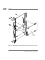
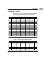
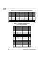
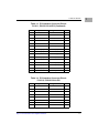
CPV8540 CompactPCI® Hot Swap PMC
Carrier Card
User Manual
CPV8540A/UM1
March 2001
© Copyright 1999, 2001 Motorola, Inc.
All rights reserved.
Printed in the United States of America.
CompactPCI® is a registered trademark of PCI Industrial Computer Manufacturers Group.
Motorola and the Motorola symbol are registered trademarks of Motorola, Inc.
All other products mentioned in this document are trademarks or registered trademarks of
their respective holders.
Safety Summary
The following general safety precautions must be observed during all phases of operation, service, and repair of this
equipment. Failure to comply with these precautions or with specific warnings elsewhere in this manual could result
in personal injury or damage to the equipment.
The safety precautions listed below represent warnings of certain dangers of which Motorola is aware. You, as the user
of the product, should follow these warnings and all other safety precautions necessary for the safe operation of the
equipment in your operating environment.
Ground the Instrument.
To minimize shock hazard, the equipment chassis and enclosure must be connected to an electrical ground. If the
equipment is supplied with a three-conductor AC power cable, the power cable must be plugged into an approved
three-contact electrical outlet, with the grounding wire (green/yellow) reliably connected to an electrical ground
(safety ground) at the power outlet. The power jack and mating plug of the power cable meet International
Electrotechnical Commission (IEC) safety standards and local electrical regulatory codes.
Do Not Operate in an Explosive Atmosphere.
Do not operate the equipment in any explosive atmosphere such as in the presence of flammable gases or fumes.
Operation of any electrical equipment in such an environment could result in an explosion and cause injury or damage.
Keep Away From Live Circuits Inside the Equipment.
Operating personnel must not remove equipment covers. Only Factory Authorized Service Personnel or other
qualified service personnel may remove equipment covers for internal subassembly or component replacement or any
internal adjustment. Service personnel should not replace components with power cable connected. Under certain
conditions, dangerous voltages may exist even with the power cable removed. To avoid injuries, such personnel should
always disconnect power and discharge circuits before touching components.
Use Caution When Exposing or Handling a CRT.
Breakage of a Cathode-Ray Tube (CRT) causes a high-velocity scattering of glass fragments (implosion). To prevent
CRT implosion, do not handle the CRT and avoid rough handling or jarring of the equipment. Handling of a CRT
should be done only by qualified service personnel using approved safety mask and gloves.
Do Not Substitute Parts or Modify Equipment.
Do not install substitute parts or perform any unauthorized modification of the equipment. Contact your local
Motorola representative for service and repair to ensure that all safety features are maintained.
Observe Warnings in Manual.
Warnings, such as the example below, precede potentially dangerous procedures throughout this manual. Instructions
contained in the warnings must be followed. You should also employ all other safety precautions which you deem
necessary for the operation of the equipment in your operating environment.
Warning
To prevent serious injury or death from dangerous voltages, use extreme
caution when handling, testing, and adjusting this equipment and its
components.
Flammability
All Motorola PWBs (printed wiring boards) are manufactured with a flammability rating
of 94V-0 by UL-recognized manufacturers.
EMI Caution
!
Caution
This equipment generates, uses and can radiate electromagnetic energy. It
may cause or be susceptible to electromagnetic interference (EMI) if not
installed and used with adequate EMI protection.
CE Notice (European Community)
Motorola Computer Group products with the CE marking comply with the EMC Directive
(89/336/EEC). Compliance with this directive implies conformity to the following
European Norms:
EN55022 “Limits and Methods of Measurement of Radio Interference Characteristics
of Information Technology Equipment”; this product tested to Equipment Class B
EN50082-1:1997 “Electromagnetic Compatibility—Generic Immunity Standard, Part
1. Residential, Commercial and Light Industry”
System products also fulfill EN60950 (product safety) which is essentially the requirement
for the Low Voltage Directive (73/23/EEC).
Board products are tested in a representative system to show compliance with the above
mentioned requirements. A proper installation in a CE-marked system will maintain the
required EMC/safety performance.
In accordance with European Community directives, a “Declaration of Conformity” has
been made and is on file within the European Union. The “Declaration of Conformity” is
available on request. Please contact your sales representative.
Notice
While reasonable efforts have been made to assure the accuracy of this document,
Motorola, Inc. assumes no liability resulting from any omissions in this document, or from
the use of the information obtained therein. Motorola reserves the right to revise this
document and to make changes from time to time in the content hereof without obligation
of Motorola to notify any person of such revision or changes.
Electronic versions of this material may be read online, downloaded for personal use, or
referenced in another document as a URL to the Motorola Computer Group website. The
text itself may not be published commercially in print or electronic form, edited, translated,
or otherwise altered without the permission of Motorola, Inc.
It is possible that this publication may contain reference to or information about Motorola
products (machines and programs), programming, or services that are not available in your
country. Such references or information must not be construed to mean that Motorola
intends to announce such Motorola products, programming, or services in your country.
Limited and Restricted Rights Legend
If the documentation contained herein is supplied, directly or indirectly, to the U.S.
Government, the following notice shall apply unless otherwise agreed to in writing by
Motorola, Inc.
Use, duplication, or disclosure by the Government is subject to restrictions as set forth in
subparagraph (b)(3) of the Rights in Technical Data clause at DFARS 252.227-7013 (Nov.
1995) and of the Rights in Noncommercial Computer Software and Documentation clause
at DFARS 252.227-7014 (Jun. 1995).
Motorola, Inc.
Computer Group
2900 South Diablo Way
Tempe, Arizona 85282
Contents
About This Manual
Summary of Changes .................................................................................................xiii
Comments and Suggestions .......................................................................................xiii
Conventions Used in This Manual.............................................................................xiv
CHAPTER 1
Introduction
Product Description and Diagrams ............................................................................1-1
Key Features .......................................................................................................1-1
Block and Schematic Diagrams..........................................................................1-2
Connector Pinouts ......................................................................................................1-5
APPENDIX A
Related Documentation
Motorola Computer Group Documents ....................................................................A-1
Manufacturers’ Documents.......................................................................................A-3
Related Specifications...............................................................................................A-3
URLs .........................................................................................................................A-4
vii
List of Figures
Figure 1-1. CPV8540 Block Diagram........................................................................1-3
Figure 1-2. PMC Modules to CPV8540 Carrier Card with Connectors Labeled ......1-4
ix
List of Tables
Table 1-1. CPCI J3 User I/O Connector Pinout .........................................................1-5
Table 1-2. CPCI J5 User I/O Connector Pinout .........................................................1-5
Table 1-3. PCI Interface Connector Pinout:
P11/J11, P21/J21 32-bit PCI ......................................................................................1-6
Table 1-4. PCI Interface Connector Pinout:
P12/J12, P22/J22 32-bit PCI ......................................................................................1-7
Table 1-5. PCI Interface Connector Pinout:
P14/J14, P24/J24 User-Defined I/O...........................................................................1-9
Table 1-6. PCI 64-bit PCI extension on PMC Connector J13, J23..........................1-10
Table A-1. Motorola Computer Group Documents .................................................A-1
Table A-2. Manufacturers’ Documents ...................................................................A-3
Table A-3. Related Specifications ...........................................................................A-3
xi
About This Manual
The CPV8540 CompactPCI Hot Swap PMC Carrier Card User Manual
provides a brief description and overview of this product. (PCI stands for
Peripheral Component Interconnect and PMC stands for PCI Mezzanine
Card.) The Manual also provides you with tables that include all the
connector pinout information needed to attach one or two PMC mezzanine
modules to the carrier card. This document should be used by anyone
attaching PMC modules to this card.
Summary of Changes
The following table lists changes made to this document since its last
release.
Date
Changes
February 2001
The CPV8540 allows only 32-bit PCI transfers. For more information, please
refer to the Note on page 1-1.
Comments and Suggestions
Motorola welcomes and appreciates your comments on its documentation.
We want to know what you think about our manuals and how we can make
them better. Mail comments to:
Motorola Computer Group
Reader Comments DW164
2900 S. Diablo Way
Tempe, Arizona 85282
You can also submit comments to the following e-mail address:
[email protected]
xiii
In all your correspondence, please list your name, position, and company.
Be sure to include the title and part number of the manual and tell how you
used it. Then tell us your feelings about its strengths and weaknesses and
any recommendations for improvements.
Conventions Used in This Manual
The following typographical conventions are used in this document:
bold
is used for user input that you type just as it appears; it is also used for
commands, options and arguments to commands, and names of
programs, directories and files.
italic
is used for names of variables to which you assign values. Italic is also
used for comments in screen displays and examples, and to introduce
new terms.
courier
is used for system output (for example, screen displays, reports),
examples, and system prompts.
<Enter>, <Return> or <CR>
<CR> represents the carriage return or Enter key.
CTRL
represents the Control key. Execute control characters by pressing the
Ctrl key and the letter simultaneously, for example, Ctrl-d.
xiv
1Introduction
1
This manual provides a brief description and overview of the CPV8540
CompactPCI Hot Swap PMC Carrier Card together with the connector
pinout information needed to attach one or two PMC mezzanine modules
to the card. PCI stands for Peripheral Component Interconnect and PMC
stands for PCI Mezzanine Card.
Note
The CPV8540 only allows 32-bit PCI transfers between itself and
the CompactPCI bus. This product is being replaced by
Motorola’s CPV8540B, which supports 64-bit PCI transfers.
Product Description and Diagrams
The CPV8540 provides connectivity to a wide variety of video, ATM,
analog, serial, and many other functions. The 8540 is a 6U CompactPCI
carrier card for IEEE P1386.1 compliant PMC modules. The board
supports one double-width or two single-width PMC mezzanine modules.
Once connected, the modules are accessed via front panel connections. In
addition, I/O lines are brought out to the carrier card’s rear 2mm pin and
socket connectors, allowing rear panel connections in systems such as the
CPX8216 HA chassis.
Key Features
The CPV8540:
❏
Supports standard (IEEEP1386.1) PMC mezzanine modules
❏
Holds one double-width or two single-width modules
❏
All PMC I/Os are brought out to the front panel and to rear
connectors
❏
Single CompactPCI load via DEC 21154 bridge
1-1
1
Introduction
❏
Supports 5.0 or 3.3 volt PMC modules
❏
Supports Plug and Play
Card ID: The CPV8540 reports itself to the system as a bridge chip with
the PMC functions behind it.
Block and Schematic Diagrams
The following two figures provide overviews of the card.
1-2
Computer Group Literature Center Web Site
Product Description and Diagrams
J5
PMC2
J3
PMC1
J2
Bridge
J1
Figure 1-1. CPV8540 Block Diagram
http://www.motorola.com/computer/literature
1-3
1
1
Introduction
J22
J21
J24
J23
J12
J11
J14
J13
Single Width
PMC Module
Figure 1-2. PMC Modules to CPV8540 Carrier Card with Connectors Labeled
1-4
Computer Group Literature Center Web Site
Connector Pinouts
Connector Pinouts
The tables in this section provide the connector pinout information needed
to attach one or two PMC mezzanine modules to the carrier card.
Table 1-1. CPCI J3 User I/O Connector Pinout
ROW A
ROW B
ROW C
ROW D
ROW E
14
+3.3V
+3.3V
+3.3V
+5V
+5V
14
13
PMC1IO5
PMC1IO4
PMC1IO3
PMC1IO2
PMC1IO1
13
12
PMC1IO10
PMC1IO9
PMC1IO8
PMC1IO7
PMC1IO6
12
11
PMC1IO15
PMC1IO14
PMC1IO13
PMC1IO12
PMC1IO11
11
10
PMC1IO20
PMC1IO19
PMC1IO18
PMC1IO17
PMC1IO16
10
9
PMC1IO25
PMC1IO24
PMC1IO23
PMC1IO22
PMC1IO21
9
8
PMC1IO30
PMC1IO29
PMC1IO28
PMC1IO27
PMC1IO26
8
7
PMC1IO35
PMC1IO34
PMC1IO33
PMC1IO32
PMC1IO31
7
6
PMC1IO40
PMC1IO39
PMC1IO38
PMC1IO37
PMC1IO36
6
5
PMC1IO45
PMC1IO44
PMC1IO43
PMC1IO42
PMC1IO41
5
4
PMC1IO50
PMC1IO49
PMC1IO48
PMC1IO47
PMC1IO46
4
3
PMC1IO55
PMC1IO54
PMC1IO53
PMC1IO52
PMC1IO51
3
2
PMC1IO60
PMC1IO59
PMC1IO58
PMC1IO57
PMC1IO56
2
1
V(I/O)
PMC1IO64
PMC1IO63
PMC1IO62
PMC1IO61
1
NOTE: PMC1IO* signals are those connected to the lower PMC Slot, or Slot 1.
Table 1-2. CPCI J5 User I/O Connector Pinout
ROW A
ROW B
ROW C
ROW D
ROW E
13
PMC2IO5
PMC2IO4
PMC2IO3
PMC2IO2
PMC2IO1
13
12
PMC2IO10
PMC2IO9
PMC2IO8
PMC2IO7
PMC2IO6
12
11
PMC2IO15
PMC2IO14
PMC2IO13
PMC2IO12
PMC2IO11
11
10
PMC2IO20
PMC2IO19
PMC2IO18
PMC2IO17
PMC2IO16
10
9
PMC2IO25
PMC2IO24
PMC2IO23
PMC2IO22
PMC2IO21
9
8
PMC2IO30
PMC2IO29
PMC2IO28
PMC2IO27
PMC2IO26
8
http://www.motorola.com/computer/literature
1-5
1
1
Introduction
Table 1-2. CPCI J5 User I/O Connector Pinout (Continued)
7
PMC2IO35
PMC2IO34
PMC2IO33
PMC2IO32
PMC2IO31
7
6
PMC2IO40
PMC2IO39
PMC2IO38
PMC2IO37
PMC2IO36
6
5
PMC2IO45
PMC2IO44
PMC2IO43
PMC2IO42
PMC2IO41
5
4
PMC2IO50
PMC2IO49
PMC2IO48
PMC2IO47
PMC2IO46
4
3
PMC2IO55
PMC2IO54
PMC2IO53
PMC2IO52
PMC2IO51
3
2
PMC2IO60
PMC2IO59
PMC2IO58
PMC2IO57
PMC2IO56
2
1
V(I/O)
PMC2IO64
PMC2IO63
PMC2IO62
PMC2IO61
1
NOTE: PMC2IO* signals are those connected to the upper PMC Slot, or Slot 2.
Table 1-3. PCI Interface Connector Pinout:
P11/J11, P21/J21 32-bit PCI
1-6
Pin#
Signal Name
Signal Name
Pin #
1
TCK
-12V
2
3
GND
INTA#
4
5
INTB#
INTC#
6
7
BUSMODE1#
+5V
8
9
INTD#
PCI-RSVD*
10
11
GND
PCI-RSVD*
12
13
CLK
GND
14
15
GND
GNT#
16
17
REQ#
+5V
18
19
V(I/O)
AD[31]
20
21
AD[28]
AD[27]
22
23
AD[25]
GND
24
25
GND
C/BE[3]#
26
27
AD[22]
AD[21]
28
29
AD[19]
+5V
30
31
V(I/O)
AD[17]
32
33
FRAME#
GND
34
Computer Group Literature Center Web Site
Connector Pinouts
Table 1-3. PCI Interface Connector Pinout:
P11/J11, P21/J21 32-bit PCI (Continued)
Pin#
Signal Name
Signal Name
Pin #
35
GND
IRDY#
36
37
DEVSEL#
+5V
38
39
GND
LOCK#
40
41
SDONE#
SBO#
42
43
PAR
GND
44
45
V(I/O)
AD[15]
46
47
AD[12]
AD[11]
48
49
AD[09]
+5V
50
51
GND
C/BE[0]#
52
53
AD[06]
AD[05]
54
55
AD[04]
GND
56
57
V(I/O)
AD[03]
58
59
AD[02]
AD[01]
60
61
AD[00]
+5V
62
63
GND
REQ64#
64
Table 1-4. PCI Interface Connector Pinout:
P12/J12, P22/J22 32-bit PCI
Pin#
Signal Name
Signal Name
Pin #
1
+12V
TRST#
2
3
TMS
TDO
4
5
TDI
GND
6
7
GND
PCI-RSVD*
8
9
PCI-RSVD*
PCI-RSVD*
10
11
BUSMODE2#
+3.3V
12
13
RST#
BUSMODE3#
14
15
+3.3V
BUSMODE4#
16
http://www.motorola.com/computer/literature
1-7
1
1
Introduction
Table 1-4. PCI Interface Connector Pinout:
P12/J12, P22/J22 32-bit PCI (Continued)
1-8
Pin#
Signal Name
Signal Name
Pin #
17
PCI-RSVD*
GND
18
19
AD[30]
AD[29]
20
21
GND
AD[26]
22
23
AD[24]
+3.3V
24
25
IDSEL
AD[23]
26
27
+3.3V
AD[20]
28
29
AD[18]
GND
30
31
AD[16]
C/BE[2]#
32
33
GND
PMC-RSVD
34
35
TRDY#
+3.3V
36
37
GND
STOP#
38
39
PERR#
GND
40
41
+3.3V
SERR#
42
43
C/BE[1]#
GND
44
45
AD[14]
AD[13]
46
47
GND
AD[10]
48
49
AD[08]
+3.3V
50
51
AD[07]
PMC-RSVD
52
53
+3.3V
PMC-RSVD
54
55
PMC-RSVD
GND
56
57
PMC-RSVD
PMC-RSVD
58
59
GND
PMC-RSVD
60
61
ACK64#
+3.3V
62
63
GND
PMC-RSVD
64
Computer Group Literature Center Web Site
Connector Pinouts
Table 1-5. PCI Interface Connector Pinout:
P14/J14, P24/J24 User-Defined I/O
Pin#
Signal Name
Signal Name
Pin #
1
I/O
I/O
2
3
I/O
I/O
4
5
I/O
I/O
6
7
I/O
I/O
8
9
I/O
I/O
10
11
I/O
I/O
12
13
I/O
I/O
14
15
I/O
I/O
16
17
I/O
I/O
18
19
I/O
I/O
20
21
I/O
I/O
22
23
I/O
I/O
24
25
I/O
I/O
26
27
I/O
I/O
28
29
I/O
I/O
30
31
I/O
I/O
32
33
I/O
I/O
34
35
I/O
I/O
36
37
I/O
I/O
38
39
I/O
I/O
40
41
I/O
I/O
42
43
I/O
I/O
44
45
I/O
I/O
46
47
I/O
I/O
48
49
I/O
I/O
50
51
I/O
I/O
52
53
I/O
I/O
54
http://www.motorola.com/computer/literature
1-9
1
1
Introduction
Table 1-5. PCI Interface Connector Pinout:
P14/J14, P24/J24 User-Defined I/O (Continued)
Pin#
Signal Name
Signal Name
Pin #
55
I/O
I/O
56
57
I/O
I/O
58
59
I/O
I/O
60
61
I/O
I/O
62
63
I/O
I/O
64
The final table, shown below, presents the last 32 bits needed to complete
the 64-bit extension.
Table 1-6. PCI 64-bit PCI extension on PMC Connector J13, J23
1-10
Pin#
Signal Name
Signal Name
Pin #
1
-
GND
2
3
GND
C/BE7#
4
5
C/BE6#
C/BE5#
6
7
C/BE4#
GND
8
9
V(I/O)
PAR64
10
11
AD63
AD62
12
13
AD61
GND
14
15
GND
AD60
16
17
AD59
AD58
18
19
AD57
GND
20
21
V(I/O)
AD56
22
23
AD55
AD54
24
25
AD53
GND
26
27
GND
AD52
28
29
AD51
AD50
30
31
AD49
GND
32
33
GND
AD48
34
35
AD47
AD46
36
Computer Group Literature Center Web Site
Connector Pinouts
Table 1-6. PCI 64-bit PCI extension on PMC Connector J13, J23 (Continued)
Pin#
Signal Name
Signal Name
Pin #
37
AD45
GND
38
39
V(I/O)
AD44
40
41
AD43
AD42
42
43
AD41
GND
44
45
GND
AD40
46
47
AD39
AD38
48
49
AD37
GND
50
51
GND
AD36
52
53
AD35
AD34
54
55
AD33
GND
56
57
V(I/O)
AD32
58
59
-
-
60
61
-
GND
62
63
GND
-
64
http://www.motorola.com/computer/literature
1-11
1
ARelated Documentation
A
Motorola Computer Group Documents
The Motorola publications listed below offer you additional information
about this product. You can obtain paper or electronic copies of Motorola
Computer Group publications by:
❏
Visiting Motorola Computer Group’s Product Catalog for more
information on PMC products at,
http://www.motorola.com/computer/literature
❏
Contacting your local Motorola sales office
❏
Visiting Motorola Computer Group’s World Wide Web literature
site, http://www.motorola.com/computer/literature
To obtain the most up-to-date product information in PDF or HTML
format, visit http://www.motorola.com/computer/literature.
Manufacturers’ Documents
For additional information, refer to the following table for manufacturers’
data sheets or user’s manuals. As an additional help, a source for the listed
document is provided. Please note that, while these sources have been
verified, the information is subject to change without notice.
Table A-1. Manufacturers’ Documents
Document Title
Motorola Publication
Number
21154 PCI-to-PCI Bridge Data Sheet; Intel Corporation
http://developer.intel.com/design/bridge/datashts/278108.htm
278108.pdf
A-1
A
Related Documentation
Related Specifications
For additional information, refer to the following table for related
specifications. As an additional help, a source for the listed document is
provided. Please note that, while these sources have been verified, the
information is subject to change without notice.
Table A-2. Related Specifications
Document Title
Motorola Publication
Number
CompactPCI Hot Swap Specification
PCI Industrial Computers Manufacturers Group (PICMG)
http://www.picmg.org/
PICMG 2.1 R1.0
IEEE - PCI Mezzanine Card Specification (PMC)
Institute of Electrical and Electronics Engineers, Inc.
P1386.1 Draft 2.0
http://standards.ieee.org/catalog/
URLs
The following URLs (uniform resource locators) may provide helpful
sources of additional information about this product, related services, and
development tools. Please note that, while these URLs have been verified,
they are subject to change without notice.
A-2
❏
Motorola Computer Group, http://www.motorola.com/computer
❏
Motorola Computer Group OEM Services,
http://www.motorola.com/computer/support
Computer Group Literature Center Web Site