1
USER'S MANUAL - Analog Control Edition
FX3G/FX3U/FX3UC SERIES PROGRAMMABLE CONTROLLERS
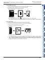
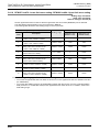
Voltage / Current Input
FX3G-2AD-BD
FX3U-4AD
FX3U-4AD-ADP
FX3UC-4AD
Voltage / Current Output
FX3G-1DA-BD
FX3U-4DA
FX3U-4DA-ADP
Voltage / Current
Input / Output Mixture
FX3U -3A-ADP
Temperature Sensor Input
FX3U-4AD-PT-ADP
FX3U-4AD-PTW-ADP
FX3U-4AD-PNK-ADP
FX3U-4AD-TC-ADP
Safety Precautions
(Read these precautions before use.)
Before installation, operation, maintenance or inspection of this product, thoroughly read through and
understand this manual and all of the associated manuals. Also, take care to handle the module properly and
safely.
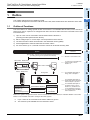
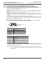
This manual classifies the safety precautions into two categories:
and
.
Indicates that incorrect handling may cause hazardous conditions, resulting in
death or severe injury.
Indicates that incorrect handling may cause hazardous conditions, resulting in
medium or slight personal injury or physical damage.
Depending on the circumstances, procedures indicated by
may also cause severe injury.
It is important to follow all precautions for personal safety.
Store this manual in a safe place so that it can be taken out and read whenever necessary. Always forward it
to the end user.
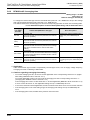
1. DESIGN PRECAUTIONS
• Make sure to have the following safety circuits outside of the PLC to ensure safe system operation even during
external power supply problems or PLC failure.
Otherwise, malfunctions may cause serious accidents.
1) Most importantly, have the following: an emergency stop circuit, a protection circuit, an interlock circuit for
opposite movements (such as normal vs. reverse rotation), and an interlock circuit (to prevent damage to the
equipment at the upper and lower positioning limits).
2) Note that when the PLC CPU detects an error, such as a watchdog timer error, during self-diagnosis, all
outputs are turned off. Also, when an error that cannot be detected by the PLC CPU occurs in an input/output
control block, output control may be disabled.
External circuits and mechanisms should be designed to ensure safe machinery operation in such a case.
3) Note that the output current of the service power supply for sensors varies depending on the model and the
absence/presence of extension blocks. If an overload occurs, the voltage automatically drops, inputs in the
PLC are disabled, and all outputs are turned off.
External circuits and mechanisms should be designed to ensure safe machinery operation in such a case.
4) Note that when an error occurs in a relay, triac or transistor output device, the output could be held either on or
off.
For output signals that may lead to serious accidents, external circuits and mechanisms should be designed to
ensure safe machinery operation in such a case.
• Do not bundle the control line together with or lay it close to the main circuit or power line.
As a guideline, lay the control line at least 100mm(3.94") or more away from the main circuit or power line.
Noise may cause malfunctions.
• Make sure to ground the shield wire or shield of the shielded cable connected to a special analog input adaptor or
special analog extension block at one point on the PLC.
However, do not use common grounding with heavy electrical systems.
Noise may cause malfunctions.
• Make sure to ground the shield wire or shield of the shielded cable connected to a special analog output adaptor
or special analog extension block at one point on the analog device side.
However, do not use common grounding with heavy electrical systems.
Noise may cause malfunctions.
• Install module so that excessive force will not be applied to the power connectors or terminal blocks.
Failure to do so may result in wire damage/breakage or PLC failure.
(1)
Safety Precautions
(Read these precautions before use.)
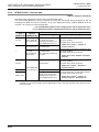
2. WIRING PRECAUTIONS
• Make sure to cut off all phases of the power supply externally before attempting wiring work.
Failure to do so may cause electric shock or damages to the product.
• Connect the DC power supply wiring to the dedicated terminals described in this manual.
If an AC power supply is connected to a DC input/output terminal or DC power supply terminal, the PLC will be
burnt out.
• Do not wire vacant terminals externally.
Doing so may damage the product.
• Perform class D grounding (grounding resistance: 100Ω or less) to the grounding terminal on the main unit.
Do not use common grounding with heavy electrical systems.
• When drilling screw holes or wiring, make sure cutting or wire debris does not enter the ventilation slits.
Failure to do so may cause fire, equipment failures or malfunctions.
• Make sure to observe the following precautions in order to prevent malfunctions under the influence of noise:
- Do not bundle the power line or twisted shielded cable together with or lay it close to the main circuit, highvoltage line, or load line.
Otherwise, noise disturbance and/or surge induction are likely to take place. As a guideline, lay the control line
at least 100mm (3.94") or more away from the main circuit, high-voltage line, or load line.
- Ground the shield of the analog input/output cable at one point on the signal receiving side.
However, do not use common grounding with heavy electrical systems.
• Make sure to properly wire to the European terminal board in accordance with the following precautions.
Failure to do so may cause electric shock, a short-circuit, wire breakage, or damage to the product.
- The disposal size of the cable end should be 9 mm (0.35").
- Tightening torque should be between 0.22 to 0.25 N•m.
- Twist the end of strand wire and make sure there are no loose wires.
- Do not solder-plate the electric wire ends.
- Do not connect more than the specified number of wires or electric wires of unspecified size.
- Affix the electric wires so that neither the terminal block nor the connected parts are directly stressed.
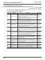
3. STARTUP AND MAINTENANCE PRECAUTIONS
• Do not touch any terminal while the PLC's power is on.
Doing so may cause electrical shock or malfunctions.
• Before cleaning or retightening terminals, cut off all phases of the power supply externally.
Failure to do so may cause electric shock.
• Before modifying or disrupting the program in operation or running the PLC, carefully read through this manual
and the associated manuals and ensure the safety of the operation.
An operation error may damage the machinery or cause accidents.
• Do not change the program in the PLC from two or more peripheral equipment devices at the same time. (i.e. from
a programming tool and a GOT)
Doing so may cause destruction or malfunction of the PLC program.
• Do not disassemble or modify the PLC.
Doing so may cause fire, equipment failures, or malfunctions.
For repair, contact your local Mitsubishi Electric distributor.
• Turn off the power to the PLC before connecting or disconnecting any extension cable.
Failure to do so may cause equipment failures or malfunctions.
• Turn of the power to the PLC before attaching or detaching the peripheral devices, expansion boards, special
adapters, and extension blocks.
Failure to do so may cause equipment failures or malfunctions.
(2)
FX3G/FX3U/FX3UC PLC User's Manual - Analog Control Edition
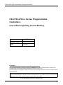
FX3G/FX3U/FX3UC Series Programmable
Controllers
User's Manual [Analog Control Edition]
Manual number
JY997D16701
Manual revision
G
Date
6/2009
Foreword
This manual describes the "analog" function of the MELSEC-F FX Series programmable controllers and
should be read and understood before attempting to install or use the unit.
Store this manual in a safe place so that you can take it out and read it whenever necessary. Always forward
it to the end user.
This manual confers no industrial property rights or any rights of any other kind, nor does it confer any patent
licenses. Mitsubishi Electric Corporation cannot be held responsible for any problems involving industrial property
rights which may occur as a result of using the contents noted in this manual.
© 2005 MITSUBISHI ELECTRIC CORPORATION
1
FX3G/FX3U/FX3UC PLC User's Manual - Analog Control Edition
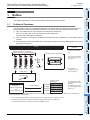
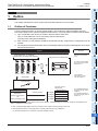
Outline Precautions
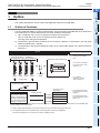
• This manual provides information for the use of the FX3U Series Programmable Controllers. The manual
has been written to be used by trained and competent personnel. The definition of such a person or
persons is as follows;
1) Any engineer who is responsible for the planning, design and construction of automatic equipment
using the product associated with this manual should be of a competent nature, trained and qualified
to the local and national standards required to fulfill that role. These engineers should be fully aware of
all aspects of safety with regards to automated equipment.
2) Any commissioning or service engineer must be of a competent nature, trained and qualified to the
local and national standards required to fulfill that job. These engineers should also be trained in the
use and maintenance of the completed product. This includes being completely familiar with all
associated documentation for the said product. All maintenance should be carried out in accordance
with established safety practices.
3) All operators of the completed equipment should be trained to use that product in a safe and
coordinated manner in compliance to established safety practices. The operators should also be
familiar with documentation which is connected with the actual operation of the completed equipment.
Note:
the term 'completed equipment' refers to a third party constructed device which contains or uses
the product associated with this manual
• This product has been manufactured as a general-purpose part for general industries, and has not been
designed or manufactured to be incorporated in a device or system used in purposes related to human life.
• Before using the product for special purposes such as nuclear power, electric power, aerospace, medicine
or passenger movement vehicles, consult with Mitsubishi Electric.
• This product has been manufactured under strict quality control. However when installing the product
where major accidents or losses could occur if the product fails, install appropriate backup or failsafe
functions in the system.
• When combining this product with other products, please confirm the standard and the code, or regulations
with which the user should follow. Moreover, please confirm the compatibility of this product to the system,
machine, and apparatus with which a user is using.
• If in doubt at any stage during the installation of the product, always consult a professional electrical
engineer who is qualified and trained to the local and national standards. If in doubt about the operation or
use, please consult the nearest Mitsubishi Electric distributor.
• Since the examples indicated by this manual, technical bulletin, catalog, etc. are used as a reference,
please use it after confirming the function and safety of the equipment and system. Mitsubishi Electric will
accept no responsibility for actual use of the product based on these illustrative examples.
• This manual content, specification etc. may be changed without a notice for improvement.
• The information in this manual has been carefully checked and is believed to be accurate; however, if you
have noticed a doubtful point, a doubtful error, etc., please contact the nearest Mitsubishi Electric
distributor.
Registration
• Microsoft® and Windows® are either registered trademarks or trademarks of Microsoft Corporation in the
United States and/or other countries.
• The company name and the product name to be described in this manual are the registered trademarks or
trademarks of each company.
2
FX3G/FX3U/FX3UC PLC User's Manual - Analog Control Edition
Table of Contents
Table of Contents
SAFETY PRECAUTIONS .................................................................................................. (1)
Common Items
1. Introduction
A-1
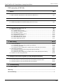
1.1 Outline and Features of Analog Control.......................................................................................A-1
1.1.1 Analog input control......................................................................................................................A-2
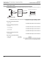
1.1.2 Analog output control....................................................................................................................A-3
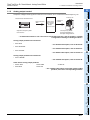
1.1.3 Temperature sensor input control.................................................................................................A-4
2. Description of Analog Products
A-5
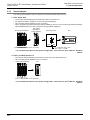
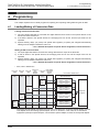
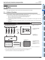
2.1 Types of Analog Products ............................................................................................................A-5
2.1.1 Expansion board...........................................................................................................................A-5
2.1.2 Special adapter.............................................................................................................................A-6
2.1.3 Special function block...................................................................................................................A-8
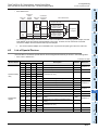
2.2 List of Analog Product Models .....................................................................................................A-9
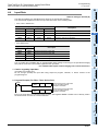
2.2.1 Expansion board...........................................................................................................................A-9
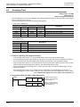
2.2.2 Special adapter.............................................................................................................................A-9
2.2.3 Special function block.................................................................................................................A-10
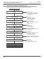
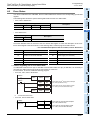
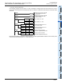
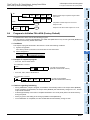
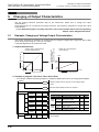
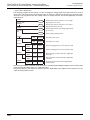
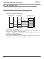
3. System Configuration Drawings of Analog Products
A-12
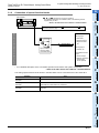
3.1 FX3U Series PLC .......................................................................................................................A-12
3.1.1 Connection of special adapters ..................................................................................................A-12
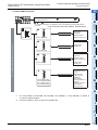
3.1.2 Connection of special function blocks ........................................................................................A-13
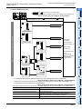
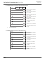
3.2 FX3UC Series PLC .....................................................................................................................A-14
3.2.1 Connection of special adapters ..................................................................................................A-14
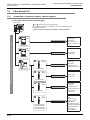
3.2.2 Connection of special function blocks ........................................................................................A-16
3.3 FX3G Series PLC .......................................................................................................................A-18
3.3.1 Connection of expansion boards, special adapters...................................................................A-18
3.3.2 Connection of special function blocks ........................................................................................A-20
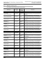
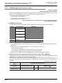
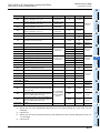
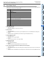
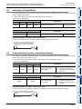
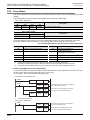
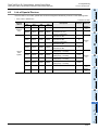
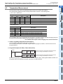
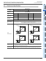
4. Comparison of Performance Specifications
A-21
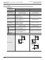
4.1 Analog Input ...............................................................................................................................A-21
4.1.1
4.1.2
4.1.3
4.1.4
4.1.5
4.1.6
4.1.7
4.1.8
FX3U-4AD-ADP ..........................................................................................................................A-21
FX2N-2AD...................................................................................................................................A-22
FX3U-4AD...................................................................................................................................A-23
FX2N-4AD...................................................................................................................................A-24
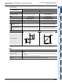
FX3UC-4AD ................................................................................................................................A-25
FX2NC-4AD ................................................................................................................................A-26
FX2N-8AD...................................................................................................................................A-27
FX3G-2AD-BD ............................................................................................................................A-28
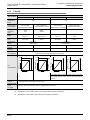
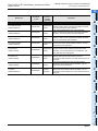
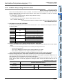
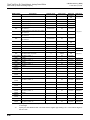
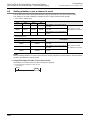
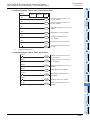
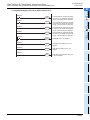
4.2 Analog Output ............................................................................................................................A-29
4.2.1
4.2.2
4.2.3
4.2.4
4.2.5
4.2.6
FX3U-4DA-ADP ..........................................................................................................................A-29
FX2N-2DA...................................................................................................................................A-30
FX3U-4DA...................................................................................................................................A-31
FX2N-4DA ..................................................................................................................................A-32
FX2NC-4DA ................................................................................................................................A-33
FX3G-1DA-BD ............................................................................................................................A-34
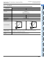
4.3 Mixed Analog Input/Output.........................................................................................................A-35
4.3.1 FX3U-3A-ADP.............................................................................................................................A-35
4.3.2 FX2N-5A .....................................................................................................................................A-36
4.3.3 FX0N-3A .....................................................................................................................................A-38
3
FX3G/FX3U/FX3UC PLC User's Manual - Analog Control Edition
Table of Contents
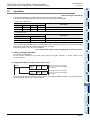
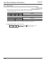
4.4 Temperature Sensor Input .........................................................................................................A-39
4.4.1
4.4.2
4.4.3
4.4.4
4.4.5
4.4.6
4.4.7
4.4.8
FX3U-4AD-PT-ADP ....................................................................................................................A-39
FX3U-4AD-PTW-ADP.................................................................................................................A-40
FX3U-4AD-PNK-ADP .................................................................................................................A-41
FX3U-4AD-TC-ADP ....................................................................................................................A-42
FX2N-4AD-PT.............................................................................................................................A-43
FX2N-4AD-TC.............................................................................................................................A-44
FX2N-8AD...................................................................................................................................A-45
FX2N-2LC ...................................................................................................................................A-46
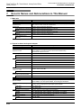
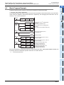
5. Version Number
A-47
5.1 PLC Main Unit ............................................................................................................................A-47
5.1.1 Manufacturer's serial number check method..............................................................................A-47
5.1.2 Version check .............................................................................................................................A-48
5.2 Special adapter ..........................................................................................................................A-48
5.2.1 Manufacturer's serial number check method..............................................................................A-48
6. Manual Introduction (Types, Contents, and Obtainment)
A-49
6.1 How to Use the Manuals ............................................................................................................A-49
6.2 Description of Related Manuals .................................................................................................A-50
6.2.1 Analog control manuals ..............................................................................................................A-50
6.2.2 Manuals related to the FX3G/FX3U/FX3UC Series PLC main unit..............................................A-50
6.2.3 Manuals of analog units..............................................................................................................A-52
7. Generic Names and Abbreviations in This Manual
4
A-54
FX3G/FX3U/FX3UC PLC User's Manual - Analog Control Edition
Table of Contents
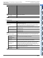
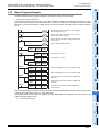
FX3U-4AD (4-channel Analog Input)
FX3UC-4AD (4-channel Analog Input)
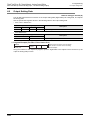
1. Outline
1.1
1.2
1.3
1.4
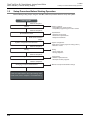
Outline of Functions .....................................................................................................................B-3
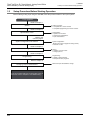
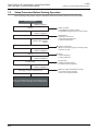
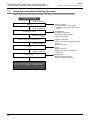
Setup Procedure Before Starting Operation ................................................................................B-4
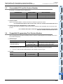
Connectable PLC and Version Numbers .....................................................................................B-5
Compatible Programming Tool Version Number .........................................................................B-5
2. Specifications
2.1
2.2
2.3
2.4
B-3
B-6
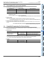
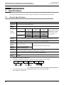
Generic Specifications .................................................................................................................B-6
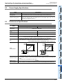
Power Supply Specifications........................................................................................................B-7
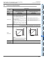
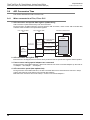
Performance Specifications .........................................................................................................B-7
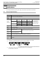
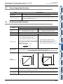
Input Mode (Characteristics) BFM #0 ..........................................................................................B-8
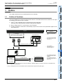
3. Wiring
B-10
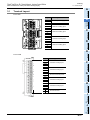
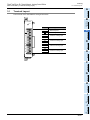
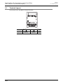
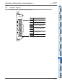
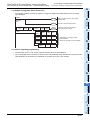
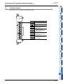
3.1 Terminal Layout .........................................................................................................................B-11
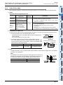
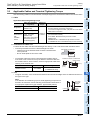
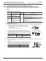
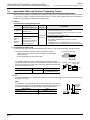
3.2 Cable and Terminal Tightening Torque......................................................................................B-12
3.2.1 Power cable (FX3UC-4AD) .........................................................................................................B-12
3.2.2 Cable (FX3U-4AD) ......................................................................................................................B-12
3.2.3 Cable (FX3UC-4AD)....................................................................................................................B-13
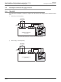
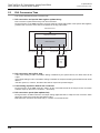
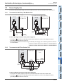
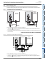
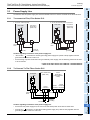
3.3 Examples of Power Supply Circuit .............................................................................................B-14
3.3.1 FX3U-4AD...................................................................................................................................B-14
3.3.2 FX3UC-4AD ................................................................................................................................B-15
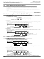
3.3.3 Cautions regarding connection of power cables.........................................................................B-15
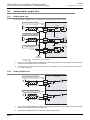
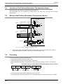
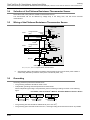
3.4 Analog Input Line .......................................................................................................................B-16
3.4.1 FX3U-4AD...................................................................................................................................B-16
3.4.2 FX3UC-4AD ................................................................................................................................B-17
3.5 Grounding ..................................................................................................................................B-17
4. Analog Input
B-18
4.1 Analog Input Procedures............................................................................................................B-18
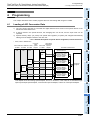
5. Buffer Memory (BFM)
B-20
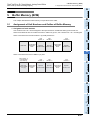
5.1 Assignment of Unit Numbers and Outline of Buffer Memory .....................................................B-20
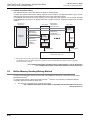
5.2 Buffer Memory Reading/Writing Method ....................................................................................B-22
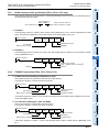
5.2.1 Buffer memory direct specification (FX3U, FX3UC PLC only).....................................................B-22
5.2.2 FROM/TO instruction (FX3G, FX3U, FX3UC PLC)......................................................................B-22
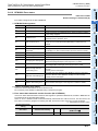
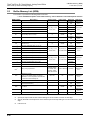
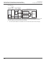
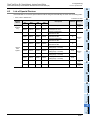
5.3 Buffer Memory List (BFM) ..........................................................................................................B-23
5.4 Buffer Memory Details................................................................................................................B-27
5.4.1 BFM #0: Input mode specification ..............................................................................................B-27
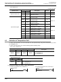
5.4.2 BFM #2 to #5: Averaging time ....................................................................................................B-28
5.4.3 BFM #6 to #9: Digital filter setting...............................................................................................B-29
5.4.4 BFM #10 to #13: Channel data...................................................................................................B-30
5.4.5 BFM #19: Data change disable ..................................................................................................B-31
5.4.6 BFM #20: Initialization function (resetting to factory default status) ...........................................B-31
5.4.7 BFM #21: Input characteristics writing........................................................................................B-31
5.4.8 BFM #22: Convenient function setting........................................................................................B-32
5.4.9 BFM #26: Upper/lower limit error status .....................................................................................B-34
5.4.10 BFM #27: Abrupt change detection status ...............................................................................B-35
5
FX3G/FX3U/FX3UC PLC User's Manual - Analog Control Edition
5.4.11
5.4.12
5.4.13
5.4.14
5.4.15
5.4.16
5.4.17
5.4.18
5.4.19
5.4.20
5.4.21
5.4.22
5.4.23
5.4.24
5.4.25
5.4.26
5.4.27
5.4.28
5.4.29
Table of Contents
BFM #28: Over-scale status .....................................................................................................B-36
BFM #29: Error status ..............................................................................................................B-37
BFM #30: Model code ..............................................................................................................B-38
BFM #41 to #44: Offset data / BFM #51 to #54: Gain data ......................................................B-38
BFM #61 to #64: Addition data .................................................................................................B-39
BFM #71 to #74: Lower limit error setting / BFM #81 to #84: Upper limit error setting.............B-40
BFM #91 to #94: Abrupt change detection value setting..........................................................B-41
BFM #99: Clearance of upper/lower limit error data and abrupt change detection data ..........B-42
BFM #101 to #104: Minimum peak value / BFM #111 to #114: Maximum peak value ............B-42
BFM #109: Minimum peak value resetting / BFM #119: Maximum peak value resetting.........B-43
BFM #125: Peak value automatic transfer to first data register specification...........................B-43
BFM #126: Upper/lower error status data automatic transfer-to data register specification.....B-44
BFM #127: Abrupt change detection status data automatic transfer-to data register
specification ...........................................................................................................................B-45
BFM #128: Over-scale status data automatic transfer-to data register specification ...............B-46
BFM #129: Error status data automatic transfer-to data register specification.........................B-46
BFM #197: Selection of cyclic data update function (function for data history) ........................B-47
BFM #198: Data history sampling time setting .........................................................................B-47
BFM #199: Data history resetting/stoppage .............................................................................B-48
BFM #200 to #6999: Data history.............................................................................................B-49
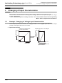
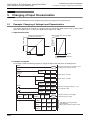
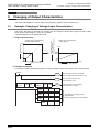
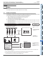
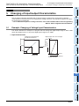
6. Changing Input Characteristics
B-50
6.1 Procedure for Changing Input Characteristics ...........................................................................B-50
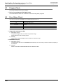
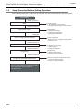
7. Examples of Practical Programs
7.1
7.2
7.3
7.4
Program That Uses Averaging Time..........................................................................................B-53
Program That Uses Convenient Functions ................................................................................B-55
Program That Uses Data History Function ................................................................................B-58
Initialization Program for 4AD (Factory Default).........................................................................B-61
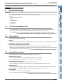
8. Troubleshooting
8.1
8.2
8.3
8.4
8.5
6
B-53
B-62
PLC Version Number Check ......................................................................................................B-62
Wiring Check..............................................................................................................................B-62
Program Check ..........................................................................................................................B-62
Error Status Check.....................................................................................................................B-63
4AD Initialization and Test Program...........................................................................................B-64
FX3G/FX3U/FX3UC PLC User's Manual - Analog Control Edition
Table of Contents
FX3U-4AD-ADP (4-channel analog Input)
1. Outline
1.1
1.2
1.3
1.4
Outline of Functions .................................................................................................................... C-3
Setup Procedure Before Starting Operation ............................................................................... C-4
Connectable PLCs and Version Number .................................................................................... C-5
Compatible Programming Tool Version Number ........................................................................ C-5
2. Specifications
2.1
2.2
2.3
2.4
C-3
C-6
Generic Specifications ................................................................................................................ C-6
Power Supply Specifications....................................................................................................... C-7
Performance Specifications ........................................................................................................ C-7
A/D Conversion Time .................................................................................................................. C-8
2.4.1 When connected to a FX3U, FX3UC PLC.................................................................................... C-8
2.4.2 When connected to a FX3G PLC................................................................................................. C-9
3. Wiring
C-10
3.1 Terminal Layout ........................................................................................................................ C-11
3.2 Applicable Cables and Terminal Tightening Torque ................................................................. C-12
3.3 Power Supply Line .................................................................................................................... C-13
3.3.1 To connect to the FX3G, FX3U Series PLC ............................................................................... C-13
3.3.2 To connect to the FX3UC Series PLC........................................................................................ C-13
3.4 Analog Input Line ...................................................................................................................... C-14
3.5 Grounding ................................................................................................................................. C-14
4. Programming
4.1
4.2
4.3
4.4
4.5
4.6
4.7
4.8
C-15
Loading of A/D Conversion Data............................................................................................... C-15
List of Special Devices .............................................................................................................. C-17
Switching of Input Mode............................................................................................................ C-18
Input Data.................................................................................................................................. C-19
Averaging Time ......................................................................................................................... C-20
Error Status ............................................................................................................................... C-21
Model Code............................................................................................................................... C-23
Basic Program Example............................................................................................................ C-24
5. Changing of Input Characteristics
C-26
5.1 Example: Changing of Voltage Input Characteristics................................................................ C-26
6. Troubleshooting
6.1
6.2
6.3
6.4
6.5
C-29
PLC Version Number Check ..................................................................................................... C-29
Wiring Check............................................................................................................................. C-29
Special Device Check ............................................................................................................... C-30
Program Check ......................................................................................................................... C-30
Error Status Check.................................................................................................................... C-31
7
FX3G/FX3U/FX3UC PLC User's Manual - Analog Control Edition
Table of Contents
FX3G-2AD-BD (2-channel analog Input)
1. Outline
1.1
1.2
1.3
1.4
D-3
Outline of Functions .................................................................................................................... D-3
Setup Procedure Before Starting Operation ............................................................................... D-4
Connectable PLCs and Version Number .................................................................................... D-5
Compatible Programming Tool Version Number ........................................................................ D-5
2. Specifications
D-6
2.1 Generic Specifications ................................................................................................................ D-6
2.2 Performance Specifications ........................................................................................................ D-7
2.3 A/D Conversion Time .................................................................................................................. D-8
3. Wiring
3.1
3.2
3.3
3.4
Terminal Layout ........................................................................................................................ D-10
Applicable Cables and Terminal Tightening Torque ................................................................. D-11
Analog Input Line ...................................................................................................................... D-12
Grounding ................................................................................................................................. D-12
4. Programming
4.1
4.2
4.3
4.4
4.5
4.6
4.7
4.8
D-9
D-13
Loading of A/D Conversion Data............................................................................................... D-13
List of Special Devices .............................................................................................................. D-14
Switching of Input Mode............................................................................................................ D-14
Input Data.................................................................................................................................. D-15
Averaging Time ......................................................................................................................... D-16
Error Status ............................................................................................................................... D-17
Model Code............................................................................................................................... D-19
Basic Program Example............................................................................................................ D-19
5. Changing of Input Characteristics
D-20
5.1 Example: Changing of Voltage Input Characteristics................................................................ D-20
6. Troubleshooting
6.1
6.2
6.3
6.4
6.5
6.6
8
D-21
PLC Version Number Check ..................................................................................................... D-21
Checking Installation ................................................................................................................. D-21
Wiring Check............................................................................................................................. D-21
Special Device Check ............................................................................................................... D-21
Program Check ......................................................................................................................... D-22
Error Status Check.................................................................................................................... D-22
FX3G/FX3U/FX3UC PLC User's Manual - Analog Control Edition
Table of Contents
FX3U-4DA (4-channel Analog Output)
1. Outline
1.1
1.2
1.3
1.4
Outline of Functions .....................................................................................................................E-3
Setup Procedure Before Starting Operation ................................................................................E-4
Connectable PLCs and Version Numbers ...................................................................................E-5
Compatible Programming Tool Version Number .........................................................................E-5
2. Specifications
2.1
2.2
2.3
2.4
E-3
E-6
Generic Specifications .................................................................................................................E-6
Power Supply Specifications........................................................................................................E-7
Performance Specifications .........................................................................................................E-7
Output Mode (Characteristics) BFM #0........................................................................................E-8
3. Wiring
E-9
3.1 Terminal Layout .........................................................................................................................E-10
3.2 Cable and Terminal Tightening Torque......................................................................................E-10
3.3 Wiring to Power Supply Terminals .............................................................................................E-11
3.3.1 Examples of Power Supply Circuit .............................................................................................E-11
3.3.2 Cautions regarding wiring to the power supply terminals ...........................................................E-11
3.4 Analog Output Wiring .................................................................................................................E-12
3.5 Grounding ..................................................................................................................................E-12
4. Analog Output
E-13
4.1 Analog Output Procedures.........................................................................................................E-13
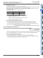
5. Buffer Memory (BFM)
E-15
5.1 Assignment of Unit Numbers and Outline of Buffer Memory .....................................................E-15
5.2 Buffer Memory Reading/Writing Method ....................................................................................E-16
5.2.1 Buffer memory direct specification (FX3U, FX3UC PLC only).....................................................E-17
5.2.2 FROM/TO instruction (FX3G, FX3U, FX3UC PLC)......................................................................E-17
5.3 Buffer Memory List (BFM) ..........................................................................................................E-18
5.4 Buffer Memory Details................................................................................................................E-21
5.4.1 BFM #0: Output mode specification ...........................................................................................E-21
5.4.2 BFM #1 to #4: Output data .........................................................................................................E-22
5.4.3 BFM #5: Output setting upon PLC stop......................................................................................E-22
5.4.4 BFM #6: Output status................................................................................................................E-23
5.4.5 BFM #9: Offset/gain setting value write command .....................................................................E-24
5.4.6 BFM #10 to #13: Offset data/BFM #14 to #17: Gain data ..........................................................E-25
5.4.7 BFM #19: Data change prohibition of setting change.................................................................E-26
5.4.8 BFM #20: Initialization function (resetting to factory default status) ...........................................E-27
5.4.9 BFM #28: Disconnection detection status (only in current output mode) ...................................E-27
5.4.10 BFM #29: Error status ..............................................................................................................E-28
5.4.11 BFM #30: Model code ..............................................................................................................E-29
5.4.12 BFM #32 to #35: Data to be output upon PLC stop..................................................................E-29
5.4.13 BFM #38: Upper/lower limit function setting .............................................................................E-30
5.4.14 BFM #39: Upper/lower limit function status ..............................................................................E-31
5.4.15 BFM #40: Clearance of upper/lower limit function status .........................................................E-31
5.4.16 BFM #41 to #44: Lower limit values of upper/lower limit function
BFM #45 to #48: Upper limit values of upper/lower limit function..........................................E-32
9
FX3G/FX3U/FX3UC PLC User's Manual - Analog Control Edition
Table of Contents
5.4.17 BFM #50: Setting of output corrective function by load resistance
(only in voltage output mode)/BFM #51 to #54: Load resistance values ...............................E-33
5.4.18 BFM #60: Status automatic transfer function setting................................................................E-34
5.4.19 BFM #61: Error status data automatic transfer-to data register specification...........................E-35
5.4.20 BFM #62: Upper/lower limit function status data automatic transfer-to data register
specification ...........................................................................................................................E-36
5.4.21 BFM #63: Specification of data register for automatic transfer at disconnection detection ......E-37
5.4.22 BFM #80 to #3098: Table output function ................................................................................E-37
6. Table Output Function
6.1
6.2
6.3
6.4
6.5
6.6
E-38
Outline of Table Output Function ...............................................................................................E-38
Preparation of data table............................................................................................................E-39
Procedures for transferring data table to buffer memory ...........................................................E-44
Procedures for executing table output function..........................................................................E-48
Details of table output error........................................................................................................E-50
Examples uses of table output function .....................................................................................E-52
7. Changing Output Characteristic
E-53
7.1 Procedure for Changing Output Characteristics ........................................................................E-53
8. Examples of Practical Programs
8.1
8.2
8.3
8.4
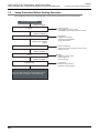
Example of Program for Analog Output Operation (Regular Operation)....................................E-56
Example of Program using Useful Functions .............................................................................E-57
Example of Program for Table Output Operation (Pattern Output Operation) ...........................E-60
Program to Initialize FX3U-4DA (Factory Default)......................................................................E-63
9. Troubleshooting
9.1
9.2
9.3
9.4
9.5
10
E-56
E-64
PLC Version Number Check ......................................................................................................E-64
Wiring Check..............................................................................................................................E-64
Program Check ..........................................................................................................................E-64
Error Status Check.....................................................................................................................E-65
FX3U-4DA Initialization and Test Program.................................................................................E-66
FX3G/FX3U/FX3UC PLC User's Manual - Analog Control Edition
Table of Contents
FX3U-4DA-ADP (4-channel analog Output)
1. Outline
1.1
1.2
1.3
1.4
Outline of Functions .....................................................................................................................F-3
Setup Procedure Before Starting Operation ................................................................................F-4
Connectable PLCs and Version Numbers ...................................................................................F-5
Compatible Programming Tool Version Number .........................................................................F-5
2. Specifications
2.1
2.2
2.3
2.4
F-3
F-6
Generic Specifications .................................................................................................................F-6
Power Supply Specifications........................................................................................................F-7
Performance Specifications .........................................................................................................F-7
D/A Conversion Time ...................................................................................................................F-8
2.4.1 When connected to a FX3U, FX3UC PLC....................................................................................F-8
2.4.2 When connected to a FX3G PLC .................................................................................................F-9
3. Wiring
F-10
3.1 Terminal Layout .........................................................................................................................F-11
3.2 Applicable Cables and Terminal Tightening Torque ..................................................................F-12
3.3 Power Supply Line .....................................................................................................................F-13
3.3.1 To Connect to the FX3G, FX3U Series PLC ...............................................................................F-13
3.3.2 To Connect To the FX3UC Series PLC.......................................................................................F-13
3.4 Analog Output Line ....................................................................................................................F-14
3.5 Grounding ..................................................................................................................................F-14
4. Programming
4.1
4.2
4.3
4.4
4.5
4.6
4.7
4.8
F-15
Writing of D/A Conversion Data .................................................................................................F-15
List of Special Devices ...............................................................................................................F-17
Switching of Output Mode ..........................................................................................................F-18
Output Holding Function Cancellation Setting ...........................................................................F-19
Output Setting Data....................................................................................................................F-20
Error Status ................................................................................................................................F-21
Model Code................................................................................................................................F-23
Basic Program Example.............................................................................................................F-23
5. Changing of Output Characteristics
F-24
5.1 Example: Changing of Voltage Output Characteristics ..............................................................F-24
6. Troubleshooting
6.1
6.2
6.3
6.4
6.5
F-26
PLC Version Number Check ......................................................................................................F-26
Wiring Check..............................................................................................................................F-26
Special Device Check ................................................................................................................F-26
Program Check ..........................................................................................................................F-27
Error Status Check.....................................................................................................................F-27
11
FX3G/FX3U/FX3UC PLC User's Manual - Analog Control Edition
Table of Contents
FX3G-1DA-BD (1-channel analog Output)
1. Outline
1.1
1.2
1.3
1.4
G-3
Outline of Functions .................................................................................................................... G-3
Setup Procedure Before Starting Operation ............................................................................... G-4
Connectable PLCs and Version Numbers .................................................................................. G-5
Compatible Programming Tool Version Number ........................................................................ G-5
2. Specifications
G-6
2.1 Generic Specifications ................................................................................................................ G-6
2.2 Performance Specifications ........................................................................................................ G-7
2.3 D/A Conversion Time .................................................................................................................. G-8
3. Wiring
3.1
3.2
3.3
3.4
Terminal Layout ........................................................................................................................ G-10
Applicable Cables and Terminal Tightening Torque ................................................................. G-11
Analog Output Line ................................................................................................................... G-12
Grounding ................................................................................................................................. G-12
4. Programming
4.1
4.2
4.3
4.4
4.5
4.6
4.7
4.8
G-9
G-13
Writing of D/A Conversion Data ................................................................................................ G-13
List of Special Devices .............................................................................................................. G-14
Switching of Output Mode ......................................................................................................... G-14
Output Holding Function Cancellation Setting .......................................................................... G-15
Output Setting Data................................................................................................................... G-15
Error Status ............................................................................................................................... G-16
Model Code............................................................................................................................... G-16
Basic Program Example............................................................................................................ G-17
5. Changing of Output Characteristics
G-18
5.1 Example: Changing of Voltage Output Characteristics ............................................................. G-18
6. Troubleshooting
6.1
6.2
6.3
6.4
6.5
6.6
12
G-19
PLC Version Number Check ..................................................................................................... G-19
Checking installation ................................................................................................................. G-19
Wiring Check............................................................................................................................. G-19
Special Device Check ............................................................................................................... G-19
Program Check ......................................................................................................................... G-20
Error Status Check.................................................................................................................... G-20
FX3G/FX3U/FX3UC PLC User's Manual - Analog Control Edition
Table of Contents
FX3U-3A-ADP
(2-channel analog Input, 1-channel analog output)
1. Outline
1.1
1.2
1.3
1.4
Outline of Functions .................................................................................................................... H-3
Setup Procedure Before Starting Operation ............................................................................... H-4
Connectable PLCs and Version Number .................................................................................... H-5
Compatible Programming Tool Version Number ........................................................................ H-5
2. Specifications
2.1
2.2
2.3
2.4
H-3
H-6
Generic Specifications ................................................................................................................ H-6
Power Supply Specifications....................................................................................................... H-6
Performance Specifications ........................................................................................................ H-7
Conversion Time ......................................................................................................................... H-8
2.4.1 When connected to a FX3U, FX3UC PLC.................................................................................... H-8
2.4.2 When connected to a FX3G PLC................................................................................................. H-9
3. Wiring
H-10
3.1 Terminal Layout ........................................................................................................................ H-11
3.2 Applicable Cables and Terminal Tightening Torque ................................................................. H-12
3.3 Power Supply Line .................................................................................................................... H-13
3.3.1 To connect to the FX3G, FX3U Series PLC ............................................................................... H-13
3.3.2 To connect to the FX3UC Series PLC........................................................................................ H-13
3.4 Analog Input / output Line ......................................................................................................... H-14
3.4.1 Analog Input Line....................................................................................................................... H-14
3.4.2 Analog Output Line.................................................................................................................... H-14
3.5 Grounding ................................................................................................................................. H-15
4. Programming
H-16
4.1 Loading/Writing of Conversion Data ......................................................................................... H-16
4.2 List of Special Devices .............................................................................................................. H-17
4.3 Switching of Input Mode............................................................................................................ H-18
4.4 Switching of Output Mode ......................................................................................................... H-19
4.5 Output Holding Function Cancellation Setting .......................................................................... H-19
4.6 Setting whether or not a channel is used .................................................................................. H-20
4.7 Input Data.................................................................................................................................. H-21
4.8 Output Setting Data................................................................................................................... H-22
4.9 Averaging Time ......................................................................................................................... H-23
4.10 Error Status ............................................................................................................................. H-24
4.11 Model Code............................................................................................................................. H-26
4.12 Basic Program Example.......................................................................................................... H-27
5. Changing of Input/output Characteristics
H-29
5.1 Example: Changing of Voltage Input Characteristics................................................................ H-29
5.2 Example: Changing of Voltage Output Characteristics ............................................................. H-32
13
FX3G/FX3U/FX3UC PLC User's Manual - Analog Control Edition
6. Troubleshooting
6.1
6.2
6.3
6.4
6.5
14
Table of Contents
H-34
PLC Version Number Check ..................................................................................................... H-34
Wiring Check............................................................................................................................. H-34
Special Device Check ............................................................................................................... H-34
Program Check ......................................................................................................................... H-35
Error Status Check.................................................................................................................... H-35
FX3G/FX3U/FX3UC PLC User's Manual - Analog Control Edition
Table of Contents
FX3U-4AD-PT-ADP
(4-channel Platinum Resistance Thermometer Data Input)
1. Outline
1.1
1.2
1.3
1.4
Outline of Functions ...................................................................................................................... I-3
Setup Procedure Before Starting Operation ................................................................................. I-4
Connectable PLC and Its Version Number ................................................................................... I-5
Compatible Programming Tool Version Number .......................................................................... I-5
2. Specifications
2.1
2.2
2.3
2.4
I-3
I-6
Generic Specifications .................................................................................................................. I-6
Power Supply Specifications......................................................................................................... I-7
Performance Specifications .......................................................................................................... I-7
A/D Conversion Time .................................................................................................................... I-8
2.4.1 When connected to a FX3U, FX3UC PLC.....................................................................................I-8
2.4.2 When connected to a FX3G PLC .................................................................................................. I-9
2.5 Temperature Measurement........................................................................................................... I-9
3. Wiring
I-10
3.1 Terminal Layout .......................................................................................................................... I-11
3.2 Applicable Cable and Terminal Tightening Torque ..................................................................... I-12
3.3 Power Supply Line ...................................................................................................................... I-13
3.3.1 To connect to FX3G, FX3U Series PLC ....................................................................................... I-13
3.3.2 To Connect To The FX3UC Series PLC ...................................................................................... I-13
3.4 Selection of the Platinum Resistance Thermometer Sensor....................................................... I-14
3.5 Wiring of the Platinum Resistance Thermometer Sensor ........................................................... I-14
3.6 Grounding ................................................................................................................................... I-14
4. Programming
4.1
4.2
4.3
4.4
4.5
4.6
4.7
4.8
Loading of A/D Conversion Data................................................................................................. I-15
List of Special Devices ................................................................................................................ I-17
Selection of Temperature Unit .................................................................................................... I-18
Temperature Measurement......................................................................................................... I-19
Averaging Time ........................................................................................................................... I-20
Error Status ................................................................................................................................. I-21
Model Code................................................................................................................................. I-24
Basic Program Example.............................................................................................................. I-25
5. Troubleshooting
5.1
5.2
5.3
5.4
5.5
I-15
I-26
PLC Version Number Check ....................................................................................................... I-26
Wiring Check............................................................................................................................... I-26
Special Device Check ................................................................................................................. I-26
Program Check ........................................................................................................................... I-27
Error Status Check...................................................................................................................... I-27
15
FX3G/FX3U/FX3UC PLC User's Manual - Analog Control Edition
Table of Contents
FX3U-4AD-PTW-ADP
(4-channel Platinum Resistance Thermometer Data Input)
1. Outline
1.1
1.2
1.3
1.4
Outline of Functions ..................................................................................................................... J-3
Setup Procedure Before Starting Operation ................................................................................ J-4
Connectable PLC and Its Version Number .................................................................................. J-5
Compatible Programming Tool Version Number ......................................................................... J-5
2. Specifications
2.1
2.2
2.3
2.4
J-3
J-6
Generic Specifications ................................................................................................................. J-6
Power Supply Specifications........................................................................................................ J-7
Performance Specifications ......................................................................................................... J-7
A/D Conversion Time ................................................................................................................... J-8
2.4.1 When connected to a FX3U, FX3UC PLC.................................................................................... J-8
2.4.2 When connected to a FX3G PLCs ............................................................................................... J-9
2.5 Temperature Measurement.......................................................................................................... J-9
3. Wiring
J-10
3.1 Terminal Layout ......................................................................................................................... J-11
3.2 Applicable Cable and Terminal Tightening Torque .................................................................... J-12
3.3 Power Supply Line ..................................................................................................................... J-13
3.3.1 To connect to FX3G, FX3U Series PLC ...................................................................................... J-13
3.3.2 To Connect To The FX3UC Series PLC ..................................................................................... J-13
3.4 Selection of the Platinum Resistance Thermometer Sensor...................................................... J-14
3.5 Wiring of the Platinum Resistance Thermometer Sensor .......................................................... J-14
3.6 Grounding .................................................................................................................................. J-14
4. Programming
4.1
4.2
4.3
4.4
4.5
4.6
4.7
4.8
Loading of A/D Conversion Data................................................................................................ J-15
List of Special Devices ............................................................................................................... J-17
Selection of Temperature Unit ................................................................................................... J-18
Temperature Measurement........................................................................................................ J-19
Averaging Time .......................................................................................................................... J-20
Error Status ................................................................................................................................ J-21
Model Code................................................................................................................................ J-24
Basic Program Example............................................................................................................. J-25
5. Troubleshooting
5.1
5.2
5.3
5.4
5.5
16
J-15
J-26
PLC Version Number Check ...................................................................................................... J-26
Wiring Check.............................................................................................................................. J-26
Special Device Check ................................................................................................................ J-26
Program Check .......................................................................................................................... J-27
Error Status Check..................................................................................................................... J-27
FX3G/FX3U/FX3UC PLC User's Manual - Analog Control Edition
Table of Contents
FX3U-4AD-PNK-ADP (4-channel Resistance Thermometer Data Input)
1. Outline
1.1
1.2
1.3
1.4
Outline of Functions .....................................................................................................................K-3
Setup Procedure Before Starting Operation ................................................................................K-4
Connectable PLC and Its Version Number ..................................................................................K-5
Compatible Programming Tool Version Number .........................................................................K-5
2. Specifications
2.1
2.2
2.3
2.4
K-3
K-6
Generic Specifications .................................................................................................................K-6
Power Supply Specifications........................................................................................................K-6
Performance Specifications .........................................................................................................K-7
A/D Conversion Time ...................................................................................................................K-8
2.4.1 When connected to a FX3U, FX3UC PLC....................................................................................K-8
2.4.2 When connected to a FX3G PLC .................................................................................................K-9
2.5 Temperature Measurement..........................................................................................................K-9
3. Wiring
K-10
3.1 Terminal Layout .........................................................................................................................K-11
3.2 Applicable Cables and Terminal Tightening Torque ..................................................................K-12
3.3 Power Supply Line .....................................................................................................................K-13
3.3.1 To connect to FX3G, FX3U Series PLC ......................................................................................K-13
3.3.2 To connect to the FX3UC Series PLC.........................................................................................K-13
3.4
3.5
3.6
3.7
Selection of the Resistance Thermometer Sensor.....................................................................K-14
Wiring of the Resistance Thermomester Sensor ......................................................................K-14
Caution Regarding Wiring ..........................................................................................................K-15
Grounding ..................................................................................................................................K-15
4. Programming
4.1
4.2
4.3
4.4
4.5
4.6
4.7
4.8
4.9
Loading of A/D Conversion Data................................................................................................K-16
List of Special Devices ...............................................................................................................K-18
Selection of Temperature Unit ...................................................................................................K-19
Input sensor selection ................................................................................................................K-20
Temperature Measurement........................................................................................................K-21
Averaging Time ..........................................................................................................................K-22
Error Status ................................................................................................................................K-23
Model Code................................................................................................................................K-26
Basic Program Example.............................................................................................................K-27
5. Troubleshooting
5.1
5.2
5.3
5.4
5.5
K-16
K-29
PLC Version Number Check ......................................................................................................K-29
Wiring Check..............................................................................................................................K-29
Special Device Check ................................................................................................................K-29
Program Check ..........................................................................................................................K-30
Error Status Check.....................................................................................................................K-30
17
FX3G/FX3U/FX3UC PLC User's Manual - Analog Control Edition
Table of Contents
FX3U-4AD-TC-ADP (4-channel Thermocouple Data Input)
1. Outline
1.1
1.2
1.3
1.4
Outline of Functions ..................................................................................................................... L-3
Setup Procedure Before Starting Operation ................................................................................ L-4
Connectable PLC and Its Version Number .................................................................................. L-5
Compatible Programming Tool Version Number ......................................................................... L-5
2. Specifications
2.1
2.2
2.3
2.4
L-3
L-6
Generic Specifications ................................................................................................................. L-6
Power Supply Specifications........................................................................................................ L-6
Performance Specifications ......................................................................................................... L-7
A/D Conversion Time ................................................................................................................... L-8
2.4.1 When connected to a FX3U, FX3UC PLC.................................................................................... L-8
2.4.2 When connected to a FX3G PLC ................................................................................................. L-9
2.5 Temperature Measurement.......................................................................................................... L-9
3. Wiring
L-10
3.1 Terminal Layout ......................................................................................................................... L-11
3.2 Applicable Cables and Terminal Tightening Torque .................................................................. L-12
3.3 Power Supply Line ..................................................................................................................... L-13
3.3.1 To connect to FX3G, FX3U Series PLC ...................................................................................... L-13
3.3.2 To connect to the FX3UC Series PLC......................................................................................... L-13
3.4 Selection of the Thermocouple .................................................................................................. L-14
3.4.1 Thermocouple type..................................................................................................................... L-14
3.4.2 Compensating lead wire ............................................................................................................. L-14
3.5 Wiring of Thermocouple ............................................................................................................. L-14
3.5.1 Wiring of thermocouple type K ................................................................................................... L-14
3.5.2 Wiring of the thermocouple type J .............................................................................................. L-15
3.6 Caution Regarding Wiring .......................................................................................................... L-15
3.7 Grounding .................................................................................................................................. L-15
4. Programming
4.1
4.2
4.3
4.4
4.5
4.6
4.7
4.8
4.9
Loading of A/D Conversion Data................................................................................................ L-16
List of Special Devices ............................................................................................................... L-18
Selection of Temperature Unit ................................................................................................... L-19
Selection of Type K or J ............................................................................................................. L-20
Temperature Measurement........................................................................................................ L-21
Averaging Time .......................................................................................................................... L-22
Error Status ................................................................................................................................ L-23
Model Code................................................................................................................................ L-26
Basic Program Example............................................................................................................. L-27
5. Troubleshooting
5.1
5.2
5.3
5.4
5.5
18
L-16
L-29
PLC Version Number Check ...................................................................................................... L-29
Wiring Check.............................................................................................................................. L-29
Special Device Check ................................................................................................................ L-29
Program Check .......................................................................................................................... L-30
Error Status Check..................................................................................................................... L-30
FX3G/FX3U/FX3UC PLC User's Manual - Analog Control Edition
Table of Contents
PID Instruction (FNC 88)
1. Outline
M-3
1.1 Outline of function ....................................................................................................................... M-3
1.2 Basic Operation Expressions in PID Instruction (Reference)...................................................... M-4
2. How to Use PID Instruction
M-5
2.1 Explanation of function and operation......................................................................................... M-5
2.2 Relationship Between Parameter Setting and Auto-Tuning........................................................ M-6
3. Parameter
M-7
3.1 Parameter List: (S3) to (S3) + 28 ................................................................................................ M-7
3.2 Details of Parameters.................................................................................................................. M-9
3.2.1
3.2.2
3.2.3
3.2.4
3.2.5
3.2.6
3.2.7
3.2.8
Sampling time (TS): (S3) ............................................................................................................. M-9
Operation setting (ACT):(S3)+1................................................................................................. M-10
Input filter (α): (S3)+2 ................................................................................................................ M-12
Proportional gain (KP): (S3)+3................................................................................................... M-13
Integral time (TI): (S3)+4 ........................................................................................................... M-13
Differential gain (KD): (S3)+5..................................................................................................... M-15
Differential time (TD): (S3)+6..................................................................................................... M-15
Alarm output flag: (S3)+24 ........................................................................................................ M-17
4. Auto-Tuning
M-18
4.1 Limit Cycle Method.................................................................................................................... M-18
4.1.1 Parameters set in auto-tuning (of limit cycle method) ............................................................... M-18
4.1.2 Auto-tuning procedure ............................................................................................................... M-19
4.1.3 Reference: How to obtain three constants in PID control (limit cycle method).......................... M-20
4.2 Step Response Method............................................................................................................. M-21
4.2.1 Parameters to be set by auto-tuning (step response method) .................................................. M-21
4.2.2 Auto-tuning procedure ............................................................................................................... M-21
4.2.3 Reference: How to obtain three constants in PID control (step response method)................... M-22
4.3 Cautions on Auto-Tuning Execution.......................................................................................... M-22
5. Example of Practical Programs (for Step Response Method)
M-23
5.1 Example: System and operation ............................................................................................... M-23
5.2 Program example of auto-tuning (step response method) and PID control .............................. M-24
5.3 Program example of auto-tuning (step response method)........................................................ M-26
6. Troubleshooting
M-28
6.1 Error Codes............................................................................................................................... M-28
Warranty...................................................................................................................................... i
Revised History ......................................................................................................................... ii
19
FX3G/FX3U/FX3UC PLC User's Manual - Analog Control Edition
MEMO
20
Table of Contents
FX3G/FX3U/FX3UC PLC User's Manual - Analog Control Edition
Common Items
1 Introduction
1.1 Outline and Features of Analog Control
A
Common Items
1.
Introduction
B
1.1
FX3U-4AD
FX3UC-4AD
This manual describes the analog products for the FX3G/FX3U/FX3UC Series PLC.
This chapter describes the analog control methods and applications.
Outline and Features of Analog Control
FX3U Series PLC
FX3UC Series PLC
FX3G Series PLC
C
FX3U-4AD-ADP
For the FX Series, there are 3 types of analog control: Voltage/Current input, Voltage/Current output, and
Temperature Sensor input.
It is important to select products that are optimum for the purpose of use.
D
FX3G-2AD-BD
E
•FX3U-4DA
•FX3U-4DA-ADP
•FX3U-3A-ADP
•FX3G-1DA-BD
→ Refer to Subsection
1.1.2.
Temperature sensor
input control type
•FX3U-4AD-PT-ADP
•FX3U-4AD-PTW-ADP
••FX3U-4AD-PNK-ADP
•FX3U-4AD-TC-ADP
F
FX3U-4DA-ADP
•FX3U-4AD
•FX3UC-4AD
•FX3U-4AD-ADP
•FX3U-3A-ADP
•FX3G-2AD-BD
→ Refer to Subsection
1.1.1.
Voltage/current
output control type
FX3U-4DA
Voltage/current input
control type
→ Refer to Subsection
1.1.3.
G
Inverter, etc.
FX3G-1DA-BD
Flowmeter,
pressure sensor, etc.
Thermocouple,
platinum resistance
thermometer
sensor
H
FX3U-3A-ADP
In addition to the above applications, the FX3U/FX3UC/FX3G Series PLC can be used for various purposes.
I
FX3U-4AD-PT
-ADP
J
FX3U-4AD-PTW
-ADP
A-1
FX3G/FX3U/FX3UC PLC User's Manual - Analog Control Edition
1 Introduction
Common Items
1.1.1
1.1 Outline and Features of Analog Control
Analog input control
Input the voltage/current signal from a flowmeter, pressure sensor, etc. to the PLC to monitor the condition of
the workpiece or equipment.
FX3U/FX3UC /FX3G Series PLC
Voltage or
current
Analog input
special function
block, special
adapter,
expansion board
A/D conversion
data
Check the flux rate using
the PLC.
Output the current or voltage
data from the flux rate or the
pressure.
→ To determine whether or not a unit can be connected to the PLC, refer to Chapter 3 "System
Configuration Drawings of Analog Products."
FX3UC Series Analog input products
• FX3UC-4AD
→ For detailed description, refer to Section B.
FX3U Series Analog input products
• FX3U-4AD
→ For detailed description, refer to Section B.
• FX3U-4AD-ADP
→ For detailed description, refer to Section C.
• FX3U-3A-ADP
→ For detailed description, refer to Section H.
FX3G Series Analog input products
• FX3G-2AD-BD
→ For detailed description, refer to Section D.
Other Series Analog input products
A-2
• FX2NC-4AD
• FX2N-4AD
• FX2N-8AD
• FX2N-2AD
• FX2N-5A
• FX0N-3A
→ For a detailed description of the other analog input
products, refer to the corresponding manuals.
FX3G/FX3U/FX3UC PLC User's Manual - Analog Control Edition
1 Introduction
Common Items
A
Analog output control
Output the voltage/current signal from the PLC to an inverter, etc. to control the inverter frequency, etc.
Inverter, etc.
FX3U/FX3UC/FX3G Series PLC
Analog output
special function
block, special
adapter,
expansion board
B
Voltage or
current
FX3U-4AD
FX3UC-4AD
D/A conversion
data
C
→ To determine whether or not a unit can be connected to the PLC, refer to Chapter 3 "System
Configuration Drawings of Analog Products."
Analog output products for FX3U Series
D
→ For detailed description, refer to Section E.
• FX3U-4DA-ADP
→ For detailed description, refer to Section F.
• FX3U-3A-ADP
→ For detailed description, refer to Section H.
• FX3G-1DA-BD
→ For detailed description, refer to Section G.
Other Series Analog output products
• FX2N-2DA
• FX2N-4DA
• FX2N-5A
F
• FX0N-3A
→ For a detailed description of the other analog output
products, refer to the corresponding manuals.
FX3U-4DA-ADP
• FX2NC-4DA
E
FX3U-4DA
Analog output products for FX3G Series
FX3G-2AD-BD
• FX3U-4DA
FX3U-4AD-ADP
The frequency will be
changed depending on
the input voltage/current.
Output the frequency data
from the PLC.
Common Items
1.1.2
1.1 Outline and Features of Analog Control
G
FX3G-1DA-BD
H
FX3U-3A-ADP
I
FX3U-4AD-PT
-ADP
J
FX3U-4AD-PTW
-ADP
A-3
FX3G/FX3U/FX3UC PLC User's Manual - Analog Control Edition
1 Introduction
Common Items
1.1.3
1.1 Outline and Features of Analog Control
Temperature sensor input control
Use the PLC to check the workpiece/machine temperature measured with a thermocouple or platinum
resistance thermometer sensor.
FX3U/FX3UC /FX3G Series PLC
Temperature data
(Analog data)
Temperature
sensor input,
special function
block or special
adapter
Temperature data
(Digital value)
Measure the
temperature of the
equipment.
Check the temperature
using the PLC.
→ To determine whether or not a unit can be connected to the PLC, refer to Chapter 3 "System
Configuration Drawings of Analog Products."
FX3U Series Temperature sensor input products
• FX3U-4AD-PT-ADP
→ For detailed description, refer to Section I.
• FX3U-4AD-PTW-ADP
→ For detailed description, refer to Section J.
• FX3U-4AD-PNK-ADP
→ For detailed description, refer to Section K.
• FX3U-4AD-TC-ADP
→ For detailed description, refer to Section L.
Other Series Temperature sensor input products
• FX2N-8AD
• FX2N-2LC
• FX2N-4AD-TC
• FX2N-4AD-PT
→ For a detailed description of the other temperature sensor input products, refer to the
corresponding manuals.
A-4
FX3G/FX3U/FX3UC PLC User's Manual - Analog Control Edition
Common Items
2 Description of Analog Products
2.1 Types of Analog Products
A
Description of Analog Products
B
Types of Analog Products
Analog input/output products are required to perform analog control using the FX Series PLC.
There are 3 types of input/output products: the expansion board, special adapter and the special function
block.
Subsequent subsections explain differences among analog products.
C
FX3U-4AD-ADP
2.1.1
FX3U-4AD
FX3UC-4AD
2.1
Common Items
2.
Expansion board
The analog expansion board uses PLC devices to send/receive data to/from the PLC.
1. FX3G Series PLC
D
• Connect analog expansion boards to option connectors of an FX3G PLC.
FX3G-2AD-BD
• Up to 2*1 analog expansion boards can be connected.
PLC
Analog
expansion board
E
FX3U-4DA
*1.
Only 1 analog special adapter can be connected to the FX3G Series PLC(14-point and 24-point type).
When two analog expansion boards are connected to the FX3G Series PLC(40-point or 60-point type),
analog special adapters are not available in the main unit.
F
FX3U-4DA-ADP
→ For a detailed description of the system configuration, refer to the PLC User’s Manual - Hardware
Edition.
G
FX3G-1DA-BD
H
FX3U-3A-ADP
I
FX3U-4AD-PT
-ADP
J
FX3U-4AD-PTW
-ADP
A-5
FX3G/FX3U/FX3UC PLC User's Manual - Analog Control Edition
2 Description of Analog Products
Common Items
2.1.2
2.1 Types of Analog Products
Special adapter
The analog special adapter uses PLC devices to send/receive data to/from the PLC.
1. FX3U Series PLC
•
•
•
•
Connect the special adapter(s) to the left side of the FX3U Series PLC.
An expansion board is needed to connect the special adapter(s).
Up to 4 analog special adapters can be connected.
When using the high-speed input/output special adapter(s), be sure to connect the high-speed input/output
special adapter(s) first, and then connect the analog special adapter(s).
Analog special adapters
High-speed
input/output
special adapters
Expansion board
PLC
FX3U -4AD-ADP FX3U-4AD-ADP FX3U -4AD-ADP FX3U -4AD-ADP
POWER
POWER
POWER
POWER
RDA
RD
RDB
SDA
SD
SDB
SG
FX3U-***-BD
Up to 4 Analog adapters can be connected.
"***" represents "422", "232",
"485", "CNV", or "USB."
→ For a detailed description of the system configuration, refer to the PLC User’s Manual - Hardware
Edition.
2. FX3UC (D, DSS) Series PLC
• Connect the special adapter(s) to the left side of the FX3UC (D, DSS) Series PLC.
• Up to 4 analog special adapters can be connected.
Analog special adapters
PLC
FX3U -4AD-ADP FX3U-4AD-ADP FX3U -4AD-ADP FX3U-4AD-ADP
POWER
POWER
POWER
POWER
Up to 4 Analog adapters can be connected.
→ For a detailed description of the system configuration, refer to the PLC User’s Manual - Hardware
Edition.
A-6
FX3G/FX3U/FX3UC PLC User's Manual - Analog Control Edition
2 Description of Analog Products
Common Items
2.1 Types of Analog Products
A
Common Items
3. FX3UC-32MT-LT(-2) PLC
• Connect the special adapter(s) to the left side of the FX3UC-32MT-LT(-2) PLC.
• An expansion board is needed to connect the special adapter(s).
• Up to 4 analog special adapters can be connected.
Analog special adapters
Expansion board
PLC
B
FX3U-4AD-ADP FX 3U -4AD-ADP FX3U -4AD-ADP FX3U -4AD-ADP
POWER
POWER
FX3U-4AD
FX3UC-4AD
POWER
POWER
RDA
RD
RDB
SDA
SD
SDB
SG
C
FX3U-***-BD
"***" represents "422", "232", "485", "CNV", or "USB."
→ For a detailed description of the system configuration, refer to the PLC User’s Manual - Hardware Edition.
D
FX3G-2AD-BD
4. FX3G Series PLC
• Connect the special adapter(s) to the left side of the FX3G Series PLC.
• A connector conversion board is needed to connect the special adapter(s).
• Up to 2*1 analog special adapters can be connected.
Analog
special adapters
FX3U-4AD-ADP
Up to 4 Analog adapters can be connected.
Connector conversion adapter
E
PLC
FX3U-4DA
F
Up to 2 Analog adapters can be connected.
→ For a detailed description of the system configuration, refer to the PLC User’s Manual - Hardware Edition.
*1.
G
FX3G-1DA-BD
Only 1 analog special adapter can be connected to the FX3G Series PLC(14-point and 24-point type).
When two analog expansion boards are connected to FX3G Series PLC(40-point or 60-point type),
analog special adapters are not available in the main unit.
FX3U-4DA-ADP
FX3G-CNV-ADP
H
FX3U-3A-ADP
I
FX3U-4AD-PT
-ADP
J
FX3U-4AD-PTW
-ADP
A-7
FX3G/FX3U/FX3UC PLC User's Manual - Analog Control Edition
2 Description of Analog Products
Common Items
2.1.3
2.1 Types of Analog Products
Special function block
The special function block uses buffer memory (BFM) to send/receive data to/from the PLC.
1. FX3U Series PLC
• Connect the special function block(s) to the right side of the FX3U Series PLC.
• Up to 8 special function blocks can be connected.
PLC
Analog special function block
for FX3U, FX2N and FX0N
Up to 8 special function units/blocks can be
connected (excluding the special adapters).
→ For a detailed description of the system configuration, refer to the PLC User’s Manual - Hardware Edition.
2. FX3UC Series PLC
• Connect the special function block(s) to the right side of the FX3UC Series PLC.
• In some cases, FX2NC-CNV-IF or FX3UC-1PS-5V may be needed for connection.
• Up to 8*1 special function blocks can be connected.
PLC
FX3UC or FX2NC Analog
special function block
FX3UC-1PS-5V
or
FX2NC-CNV-IF
FX3U, FX2N or FX0N Analog
special function block
Up to 8*1 special function units/blocks can be connected (excluding the special adapters).
*1.
Up to 7 special function units/blocks can be connected to the FX3UC-32MT-LT(-2) PLC.
Select either FX3UC-1PS-5V or FX2NC-CNV-IF considering the current components consumption.
→ For a detailed description of the system configuration, refer to the PLC User’s Manual - Hardware Edition.
3. FX3G Series PLC
• Connect the special function block(s) to the right side of the FX3G Series PLC.
• Up to 8 special function blocks can be connected.
PLC
Analog special function block
for FX3U and FX2N
Up to 8 special function units/blocks can be
connected (excluding the special adapters).
→ For a detailed description of the system configuration, refer to the PLC User's Manual - Hardware Edition.
A-8
FX3G/FX3U/FX3UC PLC User's Manual - Analog Control Edition
2 Description of Analog Products
Common Items
2.2 List of Analog Product Models
A
List of Analog Product Models
The analog input/output products compatible with the FX3U/FX3UC/FX3G Series PLC are described below:
2.2.1
Expansion board
B
No. of
channels
Range
Resolution
Function
Reference
FX3U-4AD
FX3UC-4AD
• FX3G Series PLC
Type
Common Items
2.2
D
C
Voltage/current input
FX3G-2AD-BD
2ch
Voltage: 0V to 10V DC
Voltage: 0V to 10V DC
2.5mV(12bits)
Current: 4mA to 20mA DC
8μA(11bits)
Voltage/current output
FX3G-1DA-BD
2.2.2
1ch
Voltage and current output.
G
D
Special adapter
No. of
channels
Range
Resolution
Function
Reference
Voltage/current input
FX3U-4AD-ADP
4ch
Voltage: 0V to 10V DC
C
2.5mV(12bits) Combined use of voltage and
current outputs is possible.
4μA(12bits)
F
Voltage/current output
FX3U-4DA-ADP
4ch
Voltage: 0V to 10V DC
Current: 4mA to 20mA DC
F
Voltage/current input/output mixture
Input
2ch
Voltage: 0V to 10V DC
2.5mV(12bits)
Current: 4mA to 20mA DC
Output
1ch
Voltage: 0V to 10V DC
Combined use of voltage/
current inputs and voltage/
2.5mV(12bits) current output is possible.
4μA(12bits)
Current: 4mA to 20mA DC
5μA(12bits)
H
Temperature sensor input
4ch
Pt100: -50°C to +250°C
0.1°C
I
Pt100: -100°C to +600°C
Compatible with the platinum
resistance thermometer
sensor (Pt100).
0.2°C to 0.3°C
The product can be switched
between "Centigrade" and
"Fahrenheit."
J
Pt1000: -50°C to +250°C
4ch
0.1°C
Ni1000: -45°C to +115°C
Type K: -100°C to +1000°C 0.4°C
FX3U-4AD-TC-ADP
4ch
0.3°C
K
Compatible with
thermocouple types K and J.
The product can be switched
between "Centigrade" and
"Fahrenheit."
L
A-9
J
FX3U-4AD-PTW
-ADP
Type J: -100°C to +600°C
I
Compatible with the input
sensor (Pt1000 and Ni1000).
The product can be switched
between "Centigrade" and
"Fahrenheit."
FX3U-4AD-PT
-ADP
FX3U-4AD-PNK-ADP
H
FX3U-3A-ADP
FX3U-4AD-PTW-ADP
4ch
G
Compatible with the platinum
resistance thermometer
sensor (Pt100).
The product can be switched
between "Centigrade" and
"Fahrenheit."
FX3G-1DA-BD
FX3U-4AD-PT-ADP
FX3U-4DA-ADP
FX3U-3A-ADP
E
FX3U-4DA
Current: 4mA to 20mA DC
2.5mV(12bits) Combined use of voltage and
10μA(11bits) current inputs is possible.
FX3G-2AD-BD
Type
FX3U-4AD-ADP
Current: 4mA to 20mA DC
2.5mV(12bits) Combined use of voltage and
current inputs is possible.
8μA(11bits)
FX3G/FX3U/FX3UC PLC User's Manual - Analog Control Edition
2 Description of Analog Products
Common Items
2.2 List of Analog Product Models
2.2.3
Special function block
No. of
channels
Type
Range
Resolution
Function
Reference
Voltage/current input
FX3U-4AD*1
FX3UC-4AD*2
FX2NC-4AD*2
FX2N-8AD*1
FX2N-4AD
*1
FX2N-2AD*1
4ch
4ch
4ch
8ch
4ch
2ch
Voltage:
-10V to +10V DC
0.32mV
(with sign, 16 bits)
Current:
-20mA to +20mA DC
1.25μA
(with sign, 15 bits)
Voltage:
-10V to +10V DC
0.32mV
(with sign, 16 bits)
Current:
-20mA to +20mA DC
1.25μA
(with sign, 15 bits)
Voltage:
-10V to +10V DC
0.32mV
(with sign, 16 bits)
Current:
-20mA to +20mA DC
1.25μA
(with sign, 15 bits)
Voltage:
-10V to +10V DC
0.63mV
(with sign, 15 bits)
Current:
-20mA to +20mA DC
2.5μA
(with sign, 14 bits)
Voltage:
-10V to +10V DC
5mV
(with sign, 12 bits)
Current:
-20mA to +20mA DC
10μA
(with sign, 11 bits)
Voltage:
0V to 10V DC
2.5mV
(12bits)
Current:
4mA to 20mA DC
4μA
(12bits)
Voltage:
-10V to +10V DC
0.32mV
(with sign, 16 bits)
Current:
0mA to 20mA DC
0.63μA
(15bits)
Voltage:
-10V to +10V DC
5mV
(with sign, 12 bits)
Current:
0mA to 20mA DC
20μA
(10bits)
Voltage:
-10V to +10V DC
5 mV
(with sign, 12 bits)
Current:
0mA to 20mA DC
20μA
(10bits)
Voltage:
0V to 10V DC
2.5 mV
(12 bits)
Current:
4mA to 20mA DC
4μA
(12bits)
Combined use of voltage and
current inputs is possible. The
offset/gain can be adjusted.*3
The sampling function is
incorporated.
B
Combined use of voltage and
current inputs is possible. The
offset/gain can be adjusted.*3
The sampling function is
incorporated.
B
Combined use of voltage and
current inputs is possible.
The offset/gain can be
adjusted.*3
The sampling function is
incorporated.
*5
Combined use of voltage,
current, and thermocouple is
possible. The offset/gain can be
adjusted.*3
The sampling function is
incorporated.
*5
Combined use of voltage and
current inputs is possible.
The offset/gain can be adjusted.
*5
Combined use of voltage and
current inputs is impossible.
The offset/gain can be adjusted.
(Common to 2 input channels)
*5
Combined use of voltage and
current outputs is possible.*4
The offset/gain can be adjusted.
E
Combined use of voltage and
current outputs is possible.
The offset/gain can be adjusted.
*5
Combined use of voltage and
current outputs is possible.
The offset/gain can be adjusted.
*5
Combined use of voltage and
current outputs is possible.
The offset/gain can be adjusted.
*5
Voltage/current output
FX3U-4DA*1
FX2NC-4DA*2
FX2N-4DA*1
FX2N-2DA*1
4ch
4ch
4ch
2ch
*1. To connect this block to the FX3UC Series PLC, either the FX2NC-CNV-IF or FX3UC-1PS-5V is required.
*2. Connectable with the FX3UC Series PLC only.
*3. The offset and gain of the FX3U-4AD, FX3UC-4AD, FX2NC-4AD and FX2N-8AD cannot be adjusted for
channels using the analog value direct indication mode.
*4. The offset and gain of the FX3U-4DA cannot be adjusted for channels using the analog value mV (or μA)
specification mode.
*5. Refer to the instruction manual of the respective product.
A-10
FX3G/FX3U/FX3UC PLC User's Manual - Analog Control Edition
2 Description of Analog Products
Common Items
2.2 List of Analog Product Models
No. of
channels
Range
Resolution
Function
Reference
Voltage/current input/output mixture
Input
4ch
Output
1ch
FX0N-3A*1, *4
Output
1ch
Current:
-20mA to +20mA DC
1.25μA
(with sign, 15 bits)
Voltage:
-10V to +10V DC
5mV
(with sign, 12 bits)
Current:
0mA to 20mA DC
20μA
(10bits)
Voltage:
0V to 10V DC
40mV
(8bits)
Current:
4mA to 20mA DC
64μA
(8bits)
Voltage:
0V to 10V DC
40mV
(8bits)
Current:
4mA to 20mA DC
64μA
(8bits)
Type K:
-100°C to +1200°C
0.1°C
Type J:
-100°C to +600°C
0.1°C
Type T:
-100°C to +350°C
0.1°C
Type K:
-100°C to +1200°C
0.4°C
Type J:
-100°C to +600°C
0.3°C
Combined use of voltage and
current is possible.
The offset/gain can be
adjusted.*3
The scaling function is
incorporated.
*2
C
The input format is common to 2
channels.
The offset/gain can be adjusted.
(Common to 2 input channels)
*2
D
8ch
Pt100:
-100°C to +600°C
2ch
Pt100:
-200°C to +600°C
Compatible with thermocouple
types K and J.
The unit can be switched between
"Centigrade" and "Fahrenheit."
*2
F
Compatible with the platinum
resistance thermometer sensor
(Pt100 or JPt100).
The unit can be switched between
"Centigrade" and "Fahrenheit."
*2
Compatible with thermocouple
types K, J, R, S, E, T, B, N, PL II,
WRe5-26, U, and L.
Compatible with the platinum
resistance thermometer sensor
(Pt100, JPt100).
The unit can be switched between
0.1°C or 1°C
"Centigrade" and "Fahrenheit."
(Depends on the
sensor input range.) The temperature adjustment
function (PID operation, etc.) is
incorporated.
The peak disconnection
detection function is
incorporated.
(A CT sensor is needed.)
*2
0.2°C to 0.3°C
G
H
FX3U-3A-ADP
FX2N-2LC*1
E
FX3G-1DA-BD
Example:
Type K:
-100°C to +1300°C
*2
FX3U-4DA-ADP
FX2N-4AD-PT*1 4ch
Combined use of voltage,
current, and thermocouple is
possible.
Compatible with thermocouple
types K, J, and T.
The unit can be switched between
"Centigrade" and "Fahrenheit."
The sampling function is
incorporated.
FX3U-4DA
FX2N-4AD-TC*1 4ch
FX3G-2AD-BD
Temperature sensor input
FX2N-8AD*1
B
FX3U-4AD-ADP
Input
2ch
0.32mV
(with sign, 16 bits)
FX3U-4AD
FX3UC-4AD
FX2N-5A*1
Voltage:
-10V to +10V DC
A
Common Items
Type
I
*3. The offset and gain of the FX2N-5A cannot be adjusted for channels using the analog value direct
indication mode or analog value mV (or μA) specification mode.
A-11
J
FX3U-4AD-PTW
-ADP
*4. The FX0N-3A cannot be connected to the FX3G Series PLC.
FX3U-4AD-PT
-ADP
*1. To connect this block to the FX3UC Series PLC, either the FX2NC-CNV-IF or FX3UC-1PS-5V is required.
*2. Refer to the instruction manual of the respective product.
FX3G/FX3U/FX3UC PLC User's Manual - Analog Control Edition
3 System Configuration Drawings of Analog Products
Common Items
3.
3.1 FX3U Series PLC
System Configuration Drawings of Analog Products
This section shows drawings to describe the configuration of analog units for the FX3U/FX3UC/FX3G Series
PLC.
3.1
FX3U Series PLC
3.1.1
Connection of special adapters
FX3U Series
A
To connect special function blocks C , refer to the next page.
C
B
A , B , and C represent the connecting positions.
For a detailed installation description, refer to the following manual supplied with
your PLC.
Refer to the FX3U Series User's Manual - Hardware Edition.
B
A
RDA
RD
RDB
European terminal block
SDA
SD
SDB
SG
FX3U-***-BD*1
Analog input
• Flowmeter
• Pressure sensor
• Signal converter, etc.
FX3U-4AD-ADP
Up to 4 analog special adapters can be connected.
A
European terminal block
FX3U-4DA-ADP
A
European terminal block
Analog output
• Inverter, etc.
A
Temperature sensor
input
• Thermocouple
(types K and J)
• Resistance
thermometer
sensor (Pt1000 and
Ni1000)
• Platinum resistance
thermometer
sensor (Pt100)
European terminal block
*1.
Analog input
• Flowmeter
• Pressure sensor
• Signal converter, etc.
FX3U-3A-ADP
FX3U-4AD-TC-ADP
FX3U-4AD-PNK-ADP
FX3U-4AD-PT-ADP
FX3U-4AD-PTW-ADP
A-12
Analog output
• Inverter, etc.
An FX3U-232-BD, FX3U-485-BD, FX3U-422-BD, FX3U-USB-BD, or FX3U-CNV-BD is needed to
connect the special adapters.
FX3G/FX3U/FX3UC PLC User's Manual - Analog Control Edition
3 System Configuration Drawings of Analog Products
Common Items
A
Connection of special function blocks
FX3U Series
A
A , B , and C represent the connecting positions.
For a detailed description of installation, refer to the following manual
supplied with your PLC.
→ Refer to the FX3U Series User's Manual - Hardware Edition.
C
B
D
Analog output
• Inverter, etc.
Special function
block for FX3U,
FX2N and FX0N
• For a detailed description of the connectable special function blocks and system configuration:
→ Refer to the FX3U Series User's Manual - Hardware Edition.
Type
FX3U-4AD, FX3U-4DA
Analog special function blocks for
the FX2N
FX2N-8AD, FX2N-4AD, FX2N-2AD, FX2N-4DA, FX2N-2DA, FX2N-5A,
FX2N-4AD-PT, FX2N-4AD-TC, FX2N-2LC
Analog special function blocks for
the FX0N
FX0N-3A
G
FX3G-1DA-BD
Analog special function blocks for
the FX3U
F
FX3U-4DA-ADP
The analog special function blocks shown in the table below can be connected to the FX3U Series PLC:
E
FX3U-4DA
Temperature sensor
input
• Thermocouple
• Platinum resistance
thermometer
sensor (Pt100)
FX Series
C
FX3G-2AD-BD
Up to 8 special function blocks can be connected.
Analog input
• Flowmeter
• Pressure sensor
• Signal converter,
etc.
FX3U-4AD-ADP
Terminal block
B
FX3U-4AD
FX3UC-4AD
To connect the special adapters A or the expansion boards B ,
refer to the previous page.
C
Common Items
3.1.2
3.1 FX3U Series PLC
H
FX3U-3A-ADP
I
FX3U-4AD-PT
-ADP
J
FX3U-4AD-PTW
-ADP
A-13
FX3G/FX3U/FX3UC PLC User's Manual - Analog Control Edition
3 System Configuration Drawings of Analog Products
Common Items
3.2 FX3UC Series PLC
3.2
FX3UC Series PLC
3.2.1
Connection of special adapters
1. FX3UC (D, DSS) Series PLC
A
C1
D
C2
To connect the special function blocks C or the conversion adapters D ,
refer to Subsection 3.2.2-1.
A , C represent the connecting positions.
For a detailed description of installation, refer to the following manual supplied with to
your PLC.
→ Refer to the FX3UC Series User's Manual - Hardware Edition.
A
European terminal block
Analog input
•Flowmeter
•Pressure sensor
•Signal converter, etc.
European terminal block
Analog output
•Inverter, etc.
FX3U-4AD-ADP
Up to 4 analog special adapters can be connected.
A
FX3U-4DA-ADP
A
European terminal block
FX3U-3A-ADP
Analog output
•Inverter, etc.
A
Temperature sensor
input
•Thermocouple
(types K and J)
•Resistance
thermometer
sensor (Pt1000 and
Ni1000)
•Platinum resistance
thermometer
sensor (Pt100)
European terminal block
FX3U-4AD-TC-ADP
FX3U-4AD-PNK-ADP
FX3U-4AD-PT-ADP
FX3U-4AD-PTW-ADP
A-14
Analog input
•Flowmeter
•Pressure sensor
•Signal converter, etc.
FX3G/FX3U/FX3UC PLC User's Manual - Analog Control Edition
3 System Configuration Drawings of Analog Products
Common Items
3.2 FX3UC Series PLC
A
A
D
C1
B
C2
Common Items
2. FX3UC-32MT-LT(-2) PLC
To connect the special function blocks C or the conversion adapters D ,
refer to Subsection 3.2.2-2.
B
RDA
RD
RDB
European terminal block
SDA
SD
SDB
SG
FX3U-4AD-ADP
European terminal block
D
Analog output
•Inverter, etc.
FX3U-4DA-ADP
A
FX3U-3A-ADP
Analog output
•Inverter, etc.
*2
F
European terminal block
G
FX3G-1DA-BD
Temperature sensor
input
• Thermocouple
(types K and J)
• Resistance
thermometer
sensor (Pt1000 and
Ni1000)
• Platinum resistance
thermometer
sensor (Pt100)
FX3U-4DA-ADP
A
FX3U-4AD-TC-ADP
FX3U-4AD-PNK-ADP
FX3U-4AD-PT-ADP
FX3U-4AD-PTW-ADP
E
FX3U-4DA
European terminal block
Analog input
•Flowmeter
•Pressure sensor
•Signal converter, etc.
FX3G-2AD-BD
Up to 4 analog special adapters can be connected.
A
C
FX3U-4AD-ADP
FX3U-***-BD*1
Analog input
•Flowmeter
•Pressure sensor
•Signal converter, etc.
B
FX3U-4AD
FX3UC-4AD
A , B , and C represent the connecting positions.
For a detailed description of installation, refer to the following manual supplied with to
your PLC.
→ Refer to the FX3UC Series User's Manual - Hardware Edition.
A
H
An FX3U-232-BD, FX3U-485-BD, FX3U-422-BD, FX3U-USB-BD, or FX3U-CNV-BD is needed to
connect the special adapters.
*2.
The FX3UC-32MT-LT-2 PLC is due to be upgraded later.
FX3U-3A-ADP
*1.
I
FX3U-4AD-PT
-ADP
J
FX3U-4AD-PTW
-ADP
A-15
FX3G/FX3U/FX3UC PLC User's Manual - Analog Control Edition
3 System Configuration Drawings of Analog Products
Common Items
3.2.2
3.2 FX3UC Series PLC
Connection of special function blocks
1. FX3UC (D, DSS) Series PLC
A
C1
D
A , C , and D represent the connecting positions.
For a detailed description of installation, refer to the following manual supplied with
to your PLC.
→ Refer to the FX3UC Series User's Manual - Hardware Edition.
C2
To connect the special adapters A refer to Subsection 3.2.1-1.
C1
European terminal block
FX3UC-4AD
Up to 8 special function blocks can be connected.
C1
European terminal block
Special function
block for FX2NC
Analog input
•Flowmeter
•Pressure sensor
•Signal converter, etc.
C1
European terminal block
Analog output
•Inverter, etc.
FX3UC-4AD
C1
D
European terminal block
C1
or
C2
Temperature sensor
input
•Thermocouple
•Platinum resistance
thermometer
sensor (Pt100)
Special function
block for FX2NC
FX3UC-1PS-5V
C2
D
Terminal block
FX2NC-CNV-IF
Special function
block for FX3U,
FX2N and FX0N
• For a detailed description of special function block connectability and system configuration:
→ Refer to the FX3UC Series User's Manual - Hardware Edition.
• Use the FX3UC-1PS-5V (extension power supply unit) if the capacity of the 5V DC power supply unit
incorporated in the FX3UC Series PLC is deteriorated.
→ Refer to the FX3UC Series User's Manual - Hardware Edition.
The analog special function blocks shown in the table below can be connected to the FX3UC Series PLC:
FX Series
A-16
Type
Analog special function blocks for the FX3U
FX3U-4AD, FX3U-4DA
Analog special function blocks for the FX2NC
FX2NC-4AD, FX2NC-4DA
Analog special function blocks for the FX2N
FX2N-8AD, FX2N-4AD, FX2N-2AD, FX2N-4DA, FX2N-2DA,
FX2N-5A, FX2N-4AD-PT, FX2N-4AD-TC, FX2N-2LC
Analog special function blocks for the FX0N
FX0N-3A
FX3G/FX3U/FX3UC PLC User's Manual - Analog Control Edition
3 System Configuration Drawings of Analog Products
Common Items
3.2 FX3UC Series PLC
A
A
B
C1
D
A , B , C , and D represent the connecting positions.
For a detailed description of installation, refer to the following manual supplied with
your PLC.
→ Refer to the FX3UC Series User's Manual - Hardware Edition.
C2
Common Items
2. FX3UC-32MT-LT(-2) PLC
B
To connect the special adapters A or the expansion boards B ,
refer to Subsection 3.2.1-2.
FX3U-4AD
FX3UC-4AD
C1
European terminal block
C
FX3U-4AD-ADP
FX3UC-4AD
European terminal block
Special function
block for FX2NC
Analog input
•Flowmeter
•Pressure sensor
•Signal converter, etc.
C1
D
FX3G-2AD-BD
European terminal block
FX3UC-4AD
C1
D
European terminal block
or
C2
E
Temperature sensor
input
•Thermocouple
•Platinum resistance
thermometer
sensor (Pt100)
F
FX3U-4DA-ADP
C1
Analog output
•Inverter, etc.
Special function
block for FX2NC
FX3UC-1PS-5V
C2
G
FX3G-1DA-BD
D
Terminal block
FX2NC-CNV-IF
FX3U-4DA
Up to 7 special function blocks can be connected.
C1
Special function
block for FX3U,
FX2N and FX0N
Type
Analog special function blocks for the FX3U
FX3U-4AD, FX3U-4DA
Analog special function blocks for the FX2NC
FX2NC-4AD, FX2NC-4DA
Analog special function blocks for the FX2N
FX2N-8AD, FX2N-4AD, FX2N-2AD, FX2N-4DA, FX2N-2DA,
FX2N-5A, FX2N-4AD-PT, FX2N-4AD-TC, FX2N-2LC
Analog special function blocks for the FX0N
FX0N-3A
I
FX3U-4AD-PT
-ADP
FX Series
H
FX3U-3A-ADP
• For a detailed description of special function block connectability and system configuration:
→ Refer to the FX3UC Series User's Manual - Hardware Edition.
• Use the FX3UC-1PS-5V (extension power supply unit) if the capacity of the 5V DC power supply unit
incorporated in the FX3UC Series PLC is deteriorated.
→ Refer to the FX3UC Series User's Manual - Hardware Edition.
The analog special function blocks shown in the table below can be connected to the FX3UC Series PLC:
J
FX3U-4AD-PTW
-ADP
A-17
FX3G/FX3U/FX3UC PLC User's Manual - Analog Control Edition
3 System Configuration Drawings of Analog Products
Common Items
3.3 FX3G Series PLC
3.3
FX3G Series PLC
3.3.1
Connection of expansion boards, special adapters
1. FX3G Series PLC (14-point, 24-point type)
FX3G Series
and
represent the connecting positions.
For a detailed description of installation, refer to the following manual
supplied with your PLC.
Refer to the FX3G Series User's Manual - Hardware Edition.
Up to 1 analog expansion board, analog special adapters can be connected.
1st
board
European terminal block
Analog input
Flowmeter
Pressure sensor
Signal converter, etc.
European terminal block
Analog output
Inverter, etc.
European terminal block
Analog input
Flowmeter
Pressure sensor
Signal converter, etc.
European terminal block
Analog output
Inverter, etc.
FX3G-2AD-BD
1st
board
FX3G-1DA-BD
1st
adapter
FX3G-CNV-ADP
FX3U-4AD-ADP
1st
adapter
FX3U-4DA-ADP
1st
adapter
European terminal block
Analog output
Inverter, etc.
FX3U-3A-ADP
1st
adapter
European terminal block
FX3U-4AD-TC-ADP
FX3U-4AD-PNK-ADP
FX3U-4AD-PT-ADP
FX3U-4AD-PTW-ADP
A-18
Analog input
Flowmeter
Pressure sensor
Signal converter, etc.
Temperature sensor
input
Thermocouple
(types K and J)
Resistance
thermometer sensor
(Pt1000 and Ni1000)
Platinum resistance
thermometer
sensor (Pt100)
FX3G/FX3U/FX3UC PLC User's Manual - Analog Control Edition
3 System Configuration Drawings of Analog Products
Common Items
3.3 FX3G Series PLC
A
B
A
A
Common Items
2. FX3G Series PLC (40-point, 60-point type)
A , B , and C represent the connecting positions.
For a detailed description of installation, refer to the following manual supplied with to
your PLC.
Refer to the FX3G Series User's Manual - Hardware Edition.
C
B
B
1st
board
C
2nd
board
1st
board
C
2nd
board
European
terminal
block
European
terminal
block
FX3G-1DA-BD
Analog output
Inverter, etc.
FX3G-1DA-BD
B
1st
adapter
FX3U-4AD-ADP
A
FX3G-CNV-ADP
A
2nd
adapter
1st
adapter
FX3U-4DA-ADP
A
A
2nd
adapter
FX3U-3A-ADP
FX3U-3A-ADP
A
European
terminal
block
European
terminal
block
2nd
adapter
1st
adapter
FX3U-4AD-TC-ADP
FX3U-4AD-PNK-ADP
FX3U-4AD-PT-ADP
FX3U-4AD-PTW-ADP
European
terminal
block
European
terminal
block
Analog input
Flowmeter
Pressure sensor
Signal converter,
etc.
Analog output
Inverter, etc.
Temperature
sensor input
Thermocouple
(types K and J)
Resistance
thermometer
sensor (Pt1000
and Ni1000)
Platinum
resistance
thermometer
sensor (Pt100)
A-19
G
H
I
J
FX3U-4AD-PTW
-ADP
FX3U-4AD-TC-ADP
FX3U-4AD-PNK-ADP
FX3U-4AD-PT-ADP
FX3U-4AD-PTW-ADP
European
terminal
block
FX3U-4AD-PT
-ADP
A
Analog output
Inverter, etc.
FX3U-3A-ADP
1st
adapter
European
terminal
block
F
FX3G-1DA-BD
FX3U-4DA-ADP
European
terminal
block
Analog input
Flowmeter
Pressure sensor
Signal converter,
etc.
FX3U-4DA-ADP
FX3U-4AD-ADP
European
terminal
block
FX3U-4DA
A
2nd
adapter
D
E
Any one can be
selected.
A
C
FX3G-2AD-BD
Up to 2 analog expansion boards, analog special adapters can be connected.
FX3G-2AD-BD
B
European
terminal
block
Analog input
Flowmeter
Pressure sensor
Signal converter,
etc.
FX3U-4AD-ADP
FX3G-2AD-BD
European
terminal
block
FX3U-4AD
FX3UC-4AD
Only either A or C
can be used as 2nd.
FX3G/FX3U/FX3UC PLC User's Manual - Analog Control Edition
3 System Configuration Drawings of Analog Products
Common Items
3.3.2
3.3 FX3G Series PLC
Connection of special function blocks
FX3G Series
A
A , B , and C represent the connecting positions.
For a detailed description of installation, refer to the following manual
supplied with your PLC.
→ Refer to the FX3G Series User's Manual - Hardware Edition.
C
B
Up to 8 special function blocks can be connected.
To connect the special adapters A or the connector conversion
adapter B , refer to the previous page.
C
Terminal block
Analog input
• Flowmeter
• Pressure sensor
• Signal converter,
etc.
Analog output
• Inverter, etc.
Special function
block for FX3U
and FX2N
Temperature sensor
input
• Thermocouple
• For a detailed description of the connectable special function blocks and system configuration:
→ Refer to the FX3G Series User's Manual - Hardware Edition.
The analog special function blocks shown in the table below can be connected to the FX3G Series PLC:
FX Series
A-20
Type
Analog special function blocks for
the FX3U
FX3U-4AD, FX3U-4DA
Analog special function blocks for
the FX2N
FX2N-8AD, FX2N-4AD, FX2N-2AD, FX2N-4DA, FX2N-2DA, FX2N-5A,
FX2N-4AD-PT, FX2N-4AD-TC, FX2N-2LC
FX3G/FX3U/FX3UC PLC User's Manual - Analog Control Edition
4 Comparison of Performance Specifications
Common Items
4.1 Analog Input
A
Common Items
4.
Comparison of Performance Specifications
B
4.1
Analog Input
FX3U-4AD
FX3UC-4AD
The analog product performance specifications are shown in the following tables. Select the optimal product
for your equipment.
4.1.1
FX3U-4AD-ADP
C
Voltage input
Current input
Number of input points
4ch
D
4mA to 20mA DC
(Input resistance: 250 Ω)
-0.5V,+15V
-2mA,+30mA
Impossible to change
Impossible to change
12 bits, binary
11 bits, binary
2.5mV(10V×1/4000)
10μA(16mA×1/1600)
Ambient temperature
:25±5°C
±0.5%(±50mV) for 10V full scale
±0.5%(±80μA) for 16mA full scale
Ambient temperature
:0 to 55°C
±1.0%(±100mV) for 10V full scale
±1.0%(±160μA) for 16mA full scale
Absolute maximum input
Offset
Gain
Digital output
1600
G
20.4mA
10.2V
Digital output
4000
Digital output
1640
FX3G-1DA-BD
Input characteristics
• FX3U/FX3UC Series PLC : 200μs (Data updated every scan time.)
• FX3G Series PLC : 250μs (Data updated every scan time.)
4080
F
FX3U-4DA-ADP
Time required for A/D
conversion
E
FX3U-4DA
Resolution
FX3G-2AD-BD
0V to 10V DC
(Input resistance: 194 kΩ)
Analog input range
Overall accuracy
FX3U-4AD-ADP
FX3U-4AD-ADP
Specifications
0 4mA
20mA
Analog input
H
Insulation method
• The photocoupler is used to insulate the analog input area from the PLC.
• The DC/DC converter is used to insulate the power supply from the analog inputs.
• Channels are not insulated from each other.
FX3U-3A-ADP
Number of I/O points
occupied
0 point (This number is not related to the maximum I/O points of the PLC.)
0
10V
Analog input
I
FX3U-4AD-PT
-ADP
J
FX3U-4AD-PTW
-ADP
A-21
FX3G/FX3U/FX3UC PLC User's Manual - Analog Control Edition
4 Comparison of Performance Specifications
Common Items
4.1.2
4.1 Analog Input
FX2N-2AD
FX2N-2AD
Specifications
Voltage input
Current input
Number of input points
Analog input range*1
2ch
0V to 5V DC
0V to 10V DC
(Input resistance: 200 kΩ)
Absolute maximum input
4mA to 20mA DC
(Input resistance: 250Ω)
-0.5V,+15V
-2mA,+60mA
*2,*3
Offset
If the digital value is "0":0V to 1V
If the digital value is "4000":
Gain
12 bits, binary
Resolution
2.5mV(10V×1/4000)
*3
4.00μA(16mA×1/4000)*3
Ambient temperature:
25±5°C
-
-
Ambient temperature:
0 to 55°C
±1.0%(±100mV) for 10V full scale
±1.0%(±160μA) for 16mA full scale
2.5ms × number of selected channels
(Operation synchronized with sequence program)
Time required for A/D
conversion
4095
4000
4000
0
10V
Analog input
20.380mA
10.238V
Digital output
Input characteristics
4095
Digital input
Overall accuracy
If the digital value is "4000":20mA*2,*3
5V to 10V*2,*3
Digital output
If the digital value is "0":0mA to 4mA*2,*3
0 4mA
20mA
Analog input
Insulation method
• The photocoupler is used to insulate the analog input area from the PLC.
• Channels are not insulated from each other.
Number of I/O points
occupied
8 points (Taken from either the input or output points of the PLC.)
A-22
*1.
For FX2N-2AD, combined use of the voltage and current inputs is not possible.
*2.
Use the adjustment volume to adjust FX2N-2AD.
*3.
Adjustment of the offset or gain value will change the resolution.
FX3G/FX3U/FX3UC PLC User's Manual - Analog Control Edition
4 Comparison of Performance Specifications
Common Items
A
FX3U-4AD
FX3U-4AD
Specifications
Voltage input
Current input
Number of input points
4ch
-10V to +10V DC
(Input resistance: 200 kΩ)
-20mA to +20mA DC
4mA to 20mA DC
(Input resistance: 250 Ω)
±15V
±30mA
Absolute maximum input
B
FX3U-4AD
FX3UC-4AD
Analog input range
Common Items
4.1.3
4.1 Analog Input
-10V to
-20mA to +17mA*1,*3
Gain
-9V to +10V*1,*2
-17mA to +30mA*1,*3
Digital output
With sign, 16 bits, binary
With sign, 15 bits, binary
Resolution*4
0.32mV(20V×1/64000)
2.5mV(20V×1/8000)
1.25μA(40mA×1/32000)
5.00μA(40mA×1/8000)
Ambient temperature:
25±5°C
±0.3%(±60mV) for 20V full scale
±0.5%(±200μA) for 40mA full scale
Same accuracy for 4mA to 20mA input
Ambient temperature:
0 to 55°C
±0.5%(±100mV) for 20V full scale
±1.0%(±400μA) for 40mA full scale
Same accuracy for 4mA to 20mA input
500μs × number of selected channels*5
+10V
-32000
-32640
+20.4mA
-20mA
0
F
+20mA
-20.4mA
0
+16320
+16000
FX3U-4DA-ADP
Input characteristics*4
-10.2V
-10V
+10.2V
+32640
+32000
E
zWhen the input mode is set to "6":
FX3U-4DA
zWhen the input mode is set to "0":
-16000
-16320
zWhen the input mode is set to "3":
G
FX3G-1DA-BD
20.4mA
16400
16000
0 4mA 20mA
• The photocoupler is used to insulate the analog input area from the PLC.
• The DC/DC converter is used to insulate the power supply from the analog inputs.
• Channels are not insulated from each other.
Number of I/O points
occupied
8 points (Taken from either the input or output points of the PLC.)
H
Adjustment of the offset or gain value will not affect the resolution. In the direct indication mode, however, the
offset/gain cannot be adjusted.
*2.
The offset and the gain should satisfy the following condition:
1V ≤ (Gain - Offset)
The offset and the gain should satisfy the following condition:
3mA ≤ (Gain - Offset) ≤ 30mA
The resolution and the input/output characteristics depend on the selected mode.
If 1 or more channels use the digital filter(s), the time required for A/D conversion will be
"5 ms × number of selected channels."
*3.
*4.
*5.
I
FX3U-4AD-PT
-ADP
*1.
FX3U-3A-ADP
Insulation method
D
FX3G-2AD-BD
Time required for A/D
conversion
C
FX3U-4AD-ADP
Overall accuracy
Offset
+9V*1,*2
J
FX3U-4AD-PTW
-ADP
A-23
FX3G/FX3U/FX3UC PLC User's Manual - Analog Control Edition
4 Comparison of Performance Specifications
Common Items
4.1.4
4.1 Analog Input
FX2N-4AD
FX2N-4AD
Specifications
Voltage input
Current input
Number of input points
4ch
Analog input range
-10V to +10V DC
(Input resistance: 200kΩ)
-20mA to +20mA DC
4mA to 20mA DC
(Input resistance: 250 Ω)
±15V
±32mA
Absolute maximum input
*1,*2
-20mA to +20mA*1,*3
Offset
-5V to +5V
Gain
-4V to +15V*1,*2
Digital output
With sign, 12 bits, binary
Resolution
5mV(20V×1/4000)
With sign, 11 bits, binary
*1
20μA(40mA×1/2000)*1
Ambient temperature:
25±5°C
-
-
Ambient temperature:
0 to 55°C
±1.0%(±200mV) for 20V full scale
±1.0%(±400μA) for 40mA full scale
Same accuracy for 4mA to 20mA input
Normal conversion mode:15ms × number of selected channels
High-speed conversion mode: 6ms × number of selected channels
zWhen the input is set from -20 mA to +20 mA:
Input characteristics
-10.240V
-10V
+1600
+1000
+10.235V
+2047
+2000
0
-20mA
+10V
+32mA
Time required for A/D
conversion
0
+20mA
-32mA
Overall accuracy
-16mA to +32mA*1,*3
-2000
-2048
-1000
-1600
zWhen the input is set from 4 mA to 20 mA:
32mA
1750
1000
0 4mA
20mA
Insulation method
• The photocoupler is used to insulate the analog input area from the PLC.
• The DC/DC converter is used to insulate the power supply from the analog inputs.
• Channels are not insulated from each other.
Number of I/O points
occupied
8 points (Taken from either the input or output points of the PLC.)
A-24
*1.
Adjustment of the offset or gain value will not affect the resolution.
*2.
The offset and the gain should satisfy the following condition:
1V ≤ (Gain - Offset) ≤ 15V
*3.
The offset and the gain should satisfy the following condition:
4mA ≤ (Gain - Offset) ≤ 32mA
FX3G/FX3U/FX3UC PLC User's Manual - Analog Control Edition
4 Comparison of Performance Specifications
Common Items
A
FX3UC-4AD
FX3UC-4AD
Specifications
Voltage input
Current input
Number of input points
4ch
-10V to +10V DC
(Input resistance: 200 kΩ)
-20mA to +20mA DC
4mA to 20mA DC
(Input resistance: 250 Ω)
±15V
±30mA
Absolute maximum input
B
FX3U-4AD
FX3UC-4AD
Analog input range
Common Items
4.1.5
4.1 Analog Input
-10V to
-20mA to +17mA*1,*3
Gain
-9V to +10V*1,*2
-17mA to +30mA*1,*3
Digital output
With sign, 16 bits, binary
With sign, 15 bits, binary
Resolution*4
0.32mV(20V×1/64000)
2.5mV(20V×1/8000)
1.25μA(40mA×1/32000)
5.00μA(40mA×1/8000)
Ambient temperature:
25±5°C
±0.3%(±60mV) for 20V full scale
±0.5%(±200μA) for 40mA full scale
Same accuracy for 4mA to 20mA input
Ambient temperature:
0 to 55°C
±0.5%(±100mV) for 20V full scale
±1.0%(±400μA) for 40mA full scale
Same accuracy for 4mA to 20mA input
500μs × number of selected channels*5
+10V
-32000
-32640
+20.4mA
-20mA
0
F
+20mA
-20.4mA
0
+16320
+16000
FX3U-4DA-ADP
Input characteristics*4
-10.2V
-10V
+10.2V
+32640
+32000
E
zWhen the input mode is set to "6":
FX3U-4DA
zWhen the input mode is set to "0":
-16000
-16320
zWhen the input mode is set to "3":
G
FX3G-1DA-BD
20.4mA
16400
16000
0 4mA 20mA
• The photocoupler is used to insulate the analog input area from the PLC.
• The DC/DC converter is used to insulate the power supply from the analog inputs.
• Channels are not insulated from each other.
Number of I/O points
occupied
8 points (Taken from either the input or output points of the PLC.)
H
Adjustment of the offset or gain value will not affect the resolution. In the direct indication mode, however, the
offset/gain cannot be adjusted.
*2.
The offset and the gain should satisfy the following condition:
1V ≤ (Gain - Offset)
The offset and the gain should satisfy the following condition:
3mA ≤ (Gain - Offset) ≤ 30mA
The resolution and the input/output characteristics depend on the selected mode.
If 1 or more channels use the digital filter(s), the time required for A/D conversion will be
"5 ms × number of selected channels."
*3.
*4.
*5.
I
FX3U-4AD-PT
-ADP
*1.
FX3U-3A-ADP
Insulation method
D
FX3G-2AD-BD
Time required for A/D
conversion
C
FX3U-4AD-ADP
Overall accuracy
Offset
+9V*1,*2
J
FX3U-4AD-PTW
-ADP
A-25
FX3G/FX3U/FX3UC PLC User's Manual - Analog Control Edition
4 Comparison of Performance Specifications
Common Items
4.1.6
4.1 Analog Input
FX2NC-4AD
FX2NC-4AD
Specifications
Voltage input
Number of input points
Current input
4ch
Analog input range
-10V to +10V DC
(Input resistance: 200kΩ)
-20mA to +20mA DC
4mA to 20mA DC
(Input resistance: 250 Ω)
±15V
±30mA
Absolute maximum input
-10V to
-20mA to +17mA*1,*3
Gain
-9V to +10V*1,*2
-17mA to +30mA*1,*3
Digital output
With sign, 16 bits, binary
With sign, 15 bits, binary
Resolution*4
0.32mV(20V×1/64000)
2.5mV(20V×1/8000)
1.25μA(40mA×1/32000)
5.00μA(40mA×1/8000)
Ambient temperature:
25±5°C
±0.3%(±60mV) for 20V full scale
±0.5%(±200μA) for 40mA full scale
Same accuracy for 4mA to 20mA input
Ambient temperature:
0 to 55°C
±0.5%(±100mV) for 20V full scale
±1.0%(±400μA) for 40mA full scale
Same accuracy for 4mA to 20mA input
Time required for A/D
conversion
1ms × number of selected channels*5
Input characteristics*4
-10.2V
+16320
+16000
0
+10V
-32000
-32640
+20.4mA
-10V
zWhen the input mode is set to "6":
+10.2V
zWhen the input mode is set to "0":
+32640
+32000
-20mA 0
-20.4mA
Overall accuracy
Offset
+9V*1,*2
20mA
-16000
-16320
20.4mA
zWhen the input mode is set to "3":
16400
16000
0 4mA 20mA
Insulation method
• The photocoupler is used to insulate the analog input area from the PLC.
• The DC/DC converter is used to insulate the power supply from the analog inputs.
• Channels are not insulated from each other.
Number of I/O points
occupied
8 points (Taken from either the input or output points of the PLC.)
A-26
*1.
Adjustment of the offset or gain value will not affect the resolution. In the direct indication mode, however, the
offset/gain cannot be adjusted.
*2.
The offset and the gain should satisfy the following condition:
1V ≤ (Gain - Offset)
*3.
The offset and the gain should satisfy the following condition:
3mA ≤ (Gain - Offset) ≤ 30mA
*4.
The resolution and the input/output characteristics depend on the selected mode.
*5.
If 1 or more channels use the digital filter(s), the time required for A/D conversion will be
"5 ms × number of selected channels."
FX3G/FX3U/FX3UC PLC User's Manual - Analog Control Edition
4 Comparison of Performance Specifications
Common Items
A
FX2N-8AD
FX2N-8AD
Specifications
Voltage input
Current input
Number of input points
8ch
-10V to +10V DC
(Input resistance: 200 kΩ)
-20mA to +20mA DC
4mA to 20mA DC
(Input resistance: 250 Ω)
±15V
±30mA
Absolute maximum input
B
FX3U-4AD
FX3UC-4AD
Analog input range
Common Items
4.1.7
4.1 Analog Input
-10V to
-20mA to +17mA*1,*3
Gain
-9V to +10V*1,*2
-17mA to +30mA*1,*3
Digital output
With sign, 15 bits, binary
With sign, 14 bits, binary
Resolution*4
0.63mV(20V×1/32000)
2.5mV(20V×1/8000)
2.50μA(40mA×1/16000)
2.00μA(16mA×1/8000)
Ambient temperature:
25±5°C
±0.3%(±60mV) for 20V full scale
±0.3%(±120μA) for 40mA full scale
Same accuracy for 4mA to 20mA input
Ambient temperature:
0 to 55°C
±0.5%(±100mV) for 20V full scale
±0.5%(±200μA) for 40mA full scale
Same accuracy for 4mA to 20mA input
500μs × number of selected channels*5
+10.2V
-16000
-16320
-20mA
0
F
+20mA
-20.4mA
-10.2V
+10V
FX3U-4DA-ADP
Input characteristics*4
0
+8160
+8000
+20.4mA
zWhen the input mode is set to "6":
+16320
+16000
-10V
E
FX3U-4DA
zWhen the input mode is set to "0":
-8000
Approx.-8160
zWhen the input mode is set to "3":
G
20.4mA
FX3G-1DA-BD
8200
8000
0 4mA 20mA
• The photocoupler is used to insulate the analog input area from the PLC.
• The DC/DC converter is used to insulate the power supply from the analog inputs.
• Channels are not insulated from each other.
Number of I/O points
occupied
8 points (Taken from either the input or output points of the PLC.)
H
FX3U-3A-ADP
Insulation method
*1.
*3.
1V ≤ (Gain - Offset)
The offset and the gain should satisfy the following condition:
A-27
J
FX3U-4AD-PTW
-ADP
3mA ≤ (Gain - Offset) ≤ 30mA
The resolution and the input/output characteristics depend on the selected mode.
If 1 or more channels use the thermocouple input(s), the input voltage/current data conversion speed will be
"1 ms × number of selected channels."
I
FX3U-4AD-PT
-ADP
*2.
Adjustment of the offset or gain value will not affect the resolution. In the direct indication mode, however, the
offset/gain cannot be adjusted.
The offset and the gain should satisfy the following condition:
*4.
*5.
D
FX3G-2AD-BD
Time required for A/D
conversion
C
FX3U-4AD-ADP
Overall accuracy
Offset
+9V*1,*2
FX3G/FX3U/FX3UC PLC User's Manual - Analog Control Edition
4 Comparison of Performance Specifications
Common Items
4.1.8
4.1 Analog Input
FX3G-2AD-BD
FX3G-2AD-BD
Specifications
Voltage input
Current input
Number of input points
2ch
0V to 10V DC
(Input resistance: 198.7 kΩ)
4mA to 20mA DC
(Input resistance: 250 Ω)
-0.5V. +15V
-2mA, +30mA
Impossible to change
Impossible to change
12 bits, binary
11 bits, binary
2.5mV(10V×1/4000)
8μA(16mA×1/2000)
Ambient temperature:
25±5°C
±0.5%(±50mV) for 10V full scale
±0.5%(±80μA) for 16mA full scale
Ambient temperature:
0 to 55°C
±1.0%(±100mV) for 10V full scale
±1.0%(±160μA) for 16mA full scale
Analog input range
Absolute maximum input
Offset
Gain
Digital output
Overall accuracy
Resolution
Time required for A/D
conversion
180μs (Data updated every scan time.)
4080
2040
4000
Digital output
Digital output
Input characteristics
2000
10V 10.2V
0
Analog input
0 4mA
20mA 20.32mA
Analog input
Insulation method
• The analog input area is not insulated from the PLC.
• Channels are not insulated from each other.
Number of I/O points
occupied
0 point (This number is not related to the maximum I/O points of the PLC.)
A-28
FX3G/FX3U/FX3UC PLC User's Manual - Analog Control Edition
4 Comparison of Performance Specifications
Common Items
4.2 Analog Output
Analog Output
4.2.1
FX3U-4DA-ADP
A
Common Items
4.2
Offset
Current output
4ch
0V to 10V DC
(External load: 5k to 1MΩ)
4mA to 20mA DC
(External load: 500Ω or less)
Impossible to change
Impossible to change
Digital input
12 bits, binary
Resolution
2.5mV(10V×1/4000)
4μA(16mA×1/4000)
Ambient temperature:
25±5°C
±0.5%(±50mV) for 10V full scale
±0.5%(±80μA) for 16mA full scale
Ambient temperature:
0 to 55°C
±1.0%(±100mV) for 10V full scale
±1.0%(±160μA) for 16mA full scale
If the external load resistance (Rs) is less than
5kΩ, the accuracy increases as shown in the
following formula: (Increase: 100 mV per 1%)
-
E
• FX3U/FX3UC Series PLC : 200μs (Data updated every scan time.)
• FX3G Series PLC : 250μs (Data updated every scan time.)
10V
Digital input
4000
4080
4080
Analog output
0
F
20mA
4mA
0
FX3U-4DA-ADP
Output characteristics
FX3U-4DA
Time required for D/A
conversion
47×100
-0.9(%)
Rs+47
Analog output
Reference
D
FX3G-2AD-BD
Overall accuracy
C
FX3U-4AD-ADP
Gain
FX3U-4AD
FX3UC-4AD
Voltage output
Number of output points
Analog output range
B
FX3U-4DA-ADP
Specifications
G
4000
Digital input
• The photocoupler is used to insulate the analog output area from the PLC.
• The DC/DC converter is used to insulate the power supply from the analog inputs.
• Channels are not insulated from each other.
Number of I/O points
occupied
0 point (This number is not related to the maximum I/O points of the PLC.)
FX3G-1DA-BD
Insulation method
H
FX3U-3A-ADP
I
FX3U-4AD-PT
-ADP
J
FX3U-4AD-PTW
-ADP
A-29
FX3G/FX3U/FX3UC PLC User's Manual - Analog Control Edition
4 Comparison of Performance Specifications
Common Items
4.2.2
4.2 Analog Output
FX2N-2DA
FX2N-2DA
Specifications
Voltage output
Current output
Number of output points
2ch
0V to 10V DC
0V to 5V DC
(External load: 2k to 1MΩ)
4mA to 20mA DC
(External load: 400Ω or less)
Offset*1,*2
If the digital value is "0":
0V to 1V
If the digital value is "0":
4mA
Gain*1,*2
If the digital value is "4000":
5V to 10V
If the digital value is "4000":
20mA
Analog output range
Digital output
12 bits, binary
±0.1V
±0.16mA
Does not include any load fluctuation.
-
4ms × number of selected channels
(Operation synchronized with sequence program)
Time required for D/A
conversion
20mA
4095
Output characteristics
Analog output
10V
0
Digital input
4095
Overall accuracy
4μA(16mA×1/4000)*2
Analog output
Resolution
2.5mV(10V×1/4000)*2
4mA
4000
0
4000
Digital input
If the input data consists of 13 bits or more, only the lower 12 bits will be valid, and the other bits will
be ignored.
Insulation method
• The photocoupler is used to insulate the analog output area from the PLC.
• Channels are not insulated from each other.
Number of I/O points
occupied
8 points (Taken from either the input or output points of the PLC.)
A-30
*1.
Use the adjustment volume to adjust the FX2N-2DA.
*2.
Adjustment of the offset or gain value will change the resolution.
FX3G/FX3U/FX3UC PLC User's Manual - Analog Control Edition
4 Comparison of Performance Specifications
Common Items
A
FX3U-4DA
Common Items
4.2.3
4.2 Analog Output
FX3U-4DA
Specifications
Voltage output
Current output
Number of output points
4ch
B
0mA to 20mA DC
4mA to 20mA DC
(External load: 500Ω or less)
Offset
-10V to +9V*1,*2
0mA to 17mA*1,*3
Gain
-9V to +10V*1,*2
3mA to 30mA*1,*3
Digital input
With sign, 16 bits, binary
15 bits, binary
Resolution
0.32mV(20V×1/64000)*4
0.63μA(20mA×1/32000)*4
Ambient temperature:
25±5°C
±0.3%(±60mV) for 20V full scale
±0.3%(±60μA) for 20mA full scale
Same accuracy for 4mA to 20mA output
Ambient temperature:
0 to 55°C
±0.5%(±100mV) for 20V full scale
±0.5%(±100μA) for 20mA full scale
Same accuracy for 4mA to 20mA output
Includes corrective function by load fluctuation.
-
Time required for D/A
conversion
1ms (The number of selected channels will not affect this value.)
zWhen the output mode is "2":
(The dotted line is for mode 3.)
zWhen the output mode is set to "0":
+10.2V
+10V
-10V
-10.2V
4mA
0
F
32640
+32000
Analog
output
+32640
0
20mA
FX3U-4DA-ADP
-32640
-32000
E
20.4mA
FX3U-4DA
Output characteristics
D
FX3G-2AD-BD
Reference
C
FX3U-4AD-ADP
Overall accuracy
Analog output range
FX3U-4AD
FX3UC-4AD
-10V to +10V DC
(External load: 1k to 1MΩ)
32000
Digital input
• The photocoupler is used to insulate the analog output area from the PLC.
• The DC/DC converter is used to insulate the power supply from the analog output.
• Channels are not insulated from each other.
Number of I/O points
occupied
8 points (Taken from either the input or output points of the PLC.)
G
Adjustment of the offset or gain value will not affect the resolution. In the analog value specification
mode, however, the offset/gain cannot be adjusted.
*2.
The offset and the gain should satisfy the following condition:
1V ≤ (Gain - Offset) ≤ 10V
*3.
The offset and the gain should satisfy the following condition:
3mA ≤ (Gain - Offset) ≤ 30mA
*4.
Adjustment of the offset or gain value will not affect the resolution.
H
FX3U-3A-ADP
*1.
FX3G-1DA-BD
Insulation method
I
FX3U-4AD-PT
-ADP
J
FX3U-4AD-PTW
-ADP
A-31
FX3G/FX3U/FX3UC PLC User's Manual - Analog Control Edition
4 Comparison of Performance Specifications
Common Items
4.2.4
4.2 Analog Output
FX2N-4DA
FX2N-4DA
Specifications
Voltage output
Current output
Number of output points
4ch
-10V to +10V DC
(External load: 2k to 1MΩ)
0mA to 20mA DC
4mA to 20mA DC
(External load: 500Ω or less)
Offset
-5V to +5V*1,*2
-20mA to +20mA*1,*3
Gain
15 V or less, and
Gain - Offset ≥ 1V
32 mA or less, and
Gain - Offset ≥ 4mA
With sign, 12 bits, binary
10 bits, binary
5mV(10V×1/2000)*1
20μA(20mA×1/1000)*1
±1.0%(±200mV) for 20V full scale
±1.0%(±200μA) for 20mA full scale
Same accuracy for 4mA to 20mA output
Does not include any load fluctuation.
-
Resolution
Overall accuracy
Time required for D/A
conversion
2.1 ms (The number of selected channels will not affect this value.)
zWhen the output mode is set to "0":
20mA
-2048
-2000
+2047
+10V
Output characteristics
zWhen the output mode is "2":
(The dotted line is for mode 1.)
0
+2000
1023
Digital output
Analog output
Analog output range
4mA
-10V
0
Digital input
1000
Insulation method
• The photocoupler is used to insulate the analog input area from the PLC.
• The DC/DC converter is used to insulate the power supply from the analog output.
• Channels are not insulated from each other.
Number of I/O points
occupied
8 points (Taken from either the input or output points of the PLC.)
A-32
*1.
Adjustment of the offset or gain value will not affect the resolution.
*2.
The offset and the gain should satisfy the following condition:1
1V ≤ (Gain - Offset) ≤ 15V
*3.
The offset and the gain should satisfy the following condition:
4mA ≤ (Gain - Offset) ≤ 32mA
FX3G/FX3U/FX3UC PLC User's Manual - Analog Control Edition
4 Comparison of Performance Specifications
Common Items
A
FX2NC-4DA
Common Items
4.2.5
4.2 Analog Output
FX2NC-4DA
Specifications
Voltage output
Current output
Number of output points
4ch
B
0mA to 20mA DC
4mA to 20mA DC
(External load: 500Ω or less)
Offset
-5V to +5V*1,*2
-20mA to +20mA*1,*3
Gain
-4V to +15V*1,*2
-16mA to +32mA*1,*3
Digital input
With sign, 12 bits, binary
10 bits, binary
Resolution*1
5mV(20V×1/4000)
20μA(20mA×1/1000)
Ambient temperature:
25±5°C
±0.5%(±100mV) for 20V full scale
±0.5%(±100μA) for 20mA full scale
Same accuracy for 4mA to 20mA output
Ambient temperature:
0 to 55°C
±1.0%(±200mV) for 20V full scale
±1.0%(±200μA) for 20mA full scale
Same accuracy for 4mA to 20mA output
Does not include any load fluctuation.
-
Time required for D/A
conversion
2.1ms (The number of selected channels will not affect this value.)
zWhen the output mode is set to "0":
zWhen the output mode is "2":
(The dotted line is for mode 1.)
E
FX3U-4DA
+2000
4mA
0
1000
Digital input
• The photocoupler is used to insulate the analog output area from the PLC.
• The DC/DC converter is used to insulate the power supply from the analog output.
• Channels are not insulated from each other.
Number of I/O points
occupied
8 points (Taken from either the input or output points of the PLC.)
The offset and the gain should satisfy the following condition:
1V ≤ (Gain - Offset) ≤ 15V
*3.
The offset and the gain should satisfy the following condition:
4mA ≤ (Gain - Offset) ≤ 32mA
H
FX3U-3A-ADP
Adjustment of the offset or gain value will not affect the resolution.
*2.
G
FX3G-1DA-BD
Insulation method
*1.
FX3U-4DA-ADP
-10V
F
1023
0
20mA
Analog
output
-2048
-2000
+2047
+10V
Output characteristics
D
FX3G-2AD-BD
Reference
C
FX3U-4AD-ADP
Overall accuracy
Analog output range
FX3U-4AD
FX3UC-4AD
-10V to +10V DC
(External load: 2k to 1MΩ)
I
FX3U-4AD-PT
-ADP
J
FX3U-4AD-PTW
-ADP
A-33
FX3G/FX3U/FX3UC PLC User's Manual - Analog Control Edition
4 Comparison of Performance Specifications
Common Items
4.2.6
4.2 Analog Output
FX3G-1DA-BD
FX3G-1DA-BD
Specifications
Voltage output
Number of output points
Current output
1ch
0V to 10V DC
(External load: 2k to 1MΩ)
4mA to 20mA DC
(External load: 500Ω or less)
Impossible to change
Impossible to change
Digital input
12 bits, binary
11 bits, binary
Resolution
2.5mV(10V×1/4000)
8μA(16mA×1/2000)
Ambient temperature:
25±5°C
±0.5%(±50mV) for 10V full scale
±0.5%(±80μA) for 16mA full scale
Ambient temperature:
0 to 55°C
±1.0%(±100mV) for 10V full scale
±1.0%(±160μA) for 16mA full scale
Shipment adjustment is carried out by external
load resistance 2kΩ.
If external load resistance becomes larger than
2kΩ, the output voltage will increase slightly.
When the load is 1MΩ, the output voltage is
about 2% higher than the correct value.
-
Analog output range
Offset
Overall accuracy
Gain
Reference
Time required for D/A
conversion
60μs (Data updated every scan time.)
10V
Analog output
Analog output
Output characteristics
20mA
4mA
0
4000 4080
Digital input
0
Digital input
Caution:
An area of dead band is located in the region of
0V. Therefore the output analog value may not
represent the digital value accurately.
Insulation method
• The analog output area is not insulated from the PLC.
Number of I/O points
occupied
0 point (This number is not related to the maximum I/O points of the PLC.)
A-34
2000 2040
FX3G/FX3U/FX3UC PLC User's Manual - Analog Control Edition
4 Comparison of Performance Specifications
Common Items
4.3 Mixed Analog Input/Output
Mixed Analog Input/Output
4.3.1
FX3U-3A-ADP
Current input
Voltage output
Current output
2ch
1ch
4mA to 20mA DC
(Input resistance:250Ω)
0V to 10V DC
(External load:5k to 1MΩ)
4mA to 20mA DC
(External load:
500Ω or less)
-0.5V,
+15V
-2mA,
+30mA
-
-
Digital input/
output
C
12 bits, binary
Resolution
5μA(16mA×1/3200)
2.5mV(10V×1/4000)
4μA(16mA×1/4000)
Ambient
temperature:
25±5°C
±0.5%(±50mV)
for 10V full scale
±0.5%(±80μA)
for 16mA full scale
±0.5%(±50mV)
for 10V full scale
±0.5%(±80μA)
for 16mA full scale
Ambient
temperature:
0 to 55°C
±1.0%(±100mV)
for 10V full scale
±1.0%(±160μA)
for 16mA full scale
±1.0%(±100mV)
for 10V full scale
±1.0%(±160μA)
for 16mA full scale
-
E
If the external load
resistance (Rs) is less
than 5kΩ, the accuracy
increases as shown in the
following formula:
(Increase: 100 mV per
1%)
-
FX3U-4DA
Reference
-
F
0 4mA
20mA
Analog input
Digital input
Analog output
4080
4080
4000
0
H
4mA
0
4000
Digital input
I
• The photocoupler is used to insulate the analog input and output area from the PLC.
• The DC/DC converter is used to insulate the power supply from the analog input and output.
• Channels are not insulated from each other.
FX3U-4AD-PT
-ADP
Insulation
method
10V
Analog input
20mA
Analog output
Digital output
0
10V
20.4mA
3200
10.2V
3280
4000
G
FX3U-3A-ADP
4080
Digital output
• FX3U/FX3UC Series PLC :
80μs for each selected input channel + 40μs for each selected output channel
(Operation synchronized with sequence program)
• FX3G Series PLC :
90μs for each selected input channel + 50μs for each selected output channel
(Operation synchronized with sequence program)
FX3G-1DA-BD
I/O
characteristics
FX3U-4DA-ADP
47×100
-0.9(%)
Rs+47
Time required
for conversion
D
FX3G-2AD-BD
2.5mV(10V×1/4000)
FX3U-4AD-ADP
0V to 10V DC
(Input resistance:198.7kΩ)
Absolute
maximum input
FX3U-4AD
FX3UC-4AD
Voltage input
Number of input/
output points
Overall accuracy
B
FX3U-3A-ADP
Specifications
Analog input/
output range
A
Common Items
4.3
0 points
Number of I/O
points occupied (This number of points is not related to the maximum number of input/output points of the PLC.)
J
FX3U-4AD-PTW
-ADP
A-35
FX3G/FX3U/FX3UC PLC User's Manual - Analog Control Edition
4 Comparison of Performance Specifications
Common Items
4.3.2
4.3 Mixed Analog Input/Output
FX2N-5A
1. Analog input
FX2N-5A
Specifications
Voltage input
Current input
Number of input points
Analog input range
4ch
-10V to +10V DC
-100mV to +100mV DC
(Input resistance: 200kΩ)
-20mA to +20mA DC
4mA to 20mA DC
(Input resistance: 250Ω)
±15V
±30mA
Absolute maximum input
Offset
• -10V to +10V DC:
-32V to +5V DC
• -100mV to +100mV DC:
-320mV to +50mV DC
Gain
• -10V to +10V DC:
-5V to +32V, and Gain - Offset > 1V
• -100mV to +100mV DC:
-50mV to +320mV, and Gain - Offset > 10mA
Digital input/output
• -10V to +10V DC:
With sign, 16 bits, binary
• -100mV to +100mV DC:
With sign, 12 bits, binary
-10mA to +32mA, and
Gain - Offset > 1 mA
With sign, 15 bits, binary
312.5μV(20V×1/64000)
50μV(200mV×1/4000)
Resolution
1.25μA(40mA×1/32000)
10μA(40mA×1/4000)
• -10V to +10V DC:
±0.3% (±60mV) for 20V full scale
Ambient temperature:
25±5°C
• -100mV to +100mV DC:
±0.5% (±1mV) for 200mV full scale
±0.3%(±120μA) for 40mA full scale
Same accuracy for 4mA to 20mA input
• -10V to +10V DC:
±0.5% (±100mV) for 20V full scale
Ambient temperature:
0±55°C
• -100mV to +100mV DC:
±1.0% (±2mV) for 200mV full scale
±0.5%(±200μA) for 40mA full scale
Same accuracy for 4mA to 20mA input
Time required for
conversion
1ms × number of selected channels
I/O characteristics
-10.240V
-10V
+10.240V
+32767
+32000
0
+10V
-32000
-32768
zWhen the input mode is set to "2":
+32767
+32000
-20mA
+20.480mA
zWhen the input mode is set to "0":
0
+20mA
-20.480mA
Overall accuracy
-32mA to +10mA
-32000
-32768
+32767
+32000
2mA
0
-4000
A-36
20.383mA
zWhen the input mode is set to "1":
4mA 20mA
FX3G/FX3U/FX3UC PLC User's Manual - Analog Control Edition
4 Comparison of Performance Specifications
Common Items
4.3 Mixed Analog Input/Output
A
Common Items
2. Analog output
FX2N-5A
Specifications
Voltage output
Current output
Number of output points
1ch
0mA to 20mA DC
4mA to 20mA DC
(External load: 500Ω or less)
Offset
-10V to +5V
0mA to 10mA
Gain
-9V to +10V, and
Gain - Offset ≥ 1V
3 mA to 30 mA or less, and
Gain - Offset ≥ 3mA
Digital input/output
With sign, 12 bits, binary
10 bits, binary
5mV(10V×1/4000)
20μA(20mA×1/1000)
Ambient temperature:
25±5°C
±0.5% (±100mV) for 20V full scale
±0.5%(±200μA) for 40mA full scale
Same accuracy for 4mA to 20mA output
Ambient temperature:
0±55°C
±1.0% (±200mV) for 20V full scale
±1.0%(±400μA) for 40mA full scale
Same accuracy for 4mA to 20mA output
2ms
zWhen the output mode is set to "0":
zWhen the output mode is "4":
(The dotted line is for mode 2.)
+10V
+32000
E
32767
+32767
Analog output
-32768
-32000 0
FX3U-4DA
I/O characteristics
20mA
4mA
0
32000
Digital input
-10V
D
FX3G-2AD-BD
Time required for conversion
C
FX3U-4AD-ADP
Overall accuracy
Resolution
B
FX3U-4AD
FX3UC-4AD
-10V to +10V DC
(External load: 5k to 1MΩ)
Analog output range
F
FX3U-4DA-ADP
3. Other
Specifications
FX2N-5A
Number of I/O points
occupied
8 points (Taken from either the input or output points of the PLC.)
G
FX3G-1DA-BD
Insulation method
• The photocoupler is used to insulate the analog input and output area from the
PLC.
• The DC/DC converter is used to insulate the power supply from the analog input
and output.
• Channels are not insulated from each other.
H
FX3U-3A-ADP
I
FX3U-4AD-PT
-ADP
J
FX3U-4AD-PTW
-ADP
A-37
FX3G/FX3U/FX3UC PLC User's Manual - Analog Control Edition
4 Comparison of Performance Specifications
Common Items
4.3.3
4.3 Mixed Analog Input/Output
FX0N-3A
FX0N-3A
Specifications
Voltage input
Current input
Number of
input/output
points
Voltage output
Current output
2ch
1ch
0V to 10V DC
0V to 5V DC
(Input resistance: 200kΩ)
4mA to 20mA DC
(Input resistance: 250Ω)
0V to 10V DC
0V to 5V DC
(External load: 1k to 1MΩ)
4mA to 20mA DC
(External load: 500Ω)
Absolute
maximum
input
-0.5V,
+15V
-2mA,
+60mA
-
-
Offset*2*3
If the digital value is "0":
0V to 1V
If the digital value is "0":
0mA to 4mA
If the digital value is "0":
0V to 1V
If the digital value is "0":
4mA
Analog input/
output range*1
If the digital value is "250": If the digital value is "250": If the digital value is "250": If the digital value is "250":
5V to 10V
20mA
5V to 10V
20mA
0 to 250
8 bits, binary
Digital input/
output
Resolution*3
64μA(16mA×1/250)
40mV(10V×1/250)
64μA(16mA×1/250)
±0.1V
±0.16mA
±0.1V
±0.16mA
Overall
accuracy
TO instruction processing time × 2 + FROM instruction processing time
(operation synchronized with sequence program)
10V
Analog input
0 4mA
20mA
Analog input
0
Digital input
250
4mA
0
255
10.200V
0
20mA
10V
Analog output
250
255
250
20.320mA
255
Digital output
255
Analog output
Time required
for conversion
I/O
characteristics
0 to 250
8 bits, binary
40mV(10V×1/250)
Digital output
Gain*2*3
250
Digital input
If the input data consists of 9 bits or more, only the
lower 8 bits will be valid, and the other bits will be
ignored.
Insulation
method
• The photocoupler is used to insulate the analog input and output area from the PLC.
• Channels are not insulated from each other.
Number of I/O
points
occupied
8 points (Taken from either the input or output points of the PLC.)
*1.
Combined use of voltage and current inputs is not possible.
*2.
Adjustment of the volume (offset or gain) value will change the resolution.
*3.
Adjustment of the offset or gain value will change the resolution.
A-38
FX3G/FX3U/FX3UC PLC User's Manual - Analog Control Edition
4 Comparison of Performance Specifications
Common Items
4.4 Temperature Sensor Input
Temperature Sensor Input
4.4.1
FX3U-4AD-PT-ADP
A
Common Items
4.4
B
FX3U-4AD-PT-ADP
Centigrade(°C)
Fahrenheit(°F)
Number of input points
4ch
3-wire platinum resistance thermometer sensor(s)
JIS C 1604-1997
Input signal
-58°F to +482°F
-500 to +2500
-580 to +4820
0.1°C
0.18°F
Digital output
Resolution
Time required for
conversion
• FX3U/FX3UC Series PLC : 200μs (Data updated every scan time.)
• FX3G Series PLC : 250μs (Data updated every scan time.)
-55°C
0
-550
+250°C
-500 Temperature
-58°F
0
-67°F
-50°C
E
FX3U-4DA
+255°C
+4910
+4820
D
FX3G-2AD-BD
+2550
+2500
Digital
output
• Ambient temperature: 25°C±5°C ±0.5% for full scale
• Ambient temperature: 0°C to 55°C ±1.0% for full scale
Digital
output
Overall accuracy
C
FX3U-4AD-ADP
-50°C to +250°C
+491°F
Rated temperature range
Input characteristics
FX3U-4AD
FX3UC-4AD
Specifications
+482°F
-580 Temperature
-670
F
• The photocoupler is used to insulate the analog input area from the PLC.
• The DC/DC converter is used to insulate the power supply from the analog inputs.
• Channels are not insulated from each other.
Number of I/O points
occupied
0 points
(This number of points is not related to the maximum number of input/output points of the PLC.)
FX3U-4DA-ADP
Insulation method
G
FX3G-1DA-BD
H
FX3U-3A-ADP
I
FX3U-4AD-PT
-ADP
J
FX3U-4AD-PTW
-ADP
A-39
FX3G/FX3U/FX3UC PLC User's Manual - Analog Control Edition
4 Comparison of Performance Specifications
Common Items
4.4.2
4.4 Temperature Sensor Input
FX3U-4AD-PTW-ADP
FX3U-4AD-PTW-ADP
Specifications
Centigrade(°C)
Fahrenheit(°F)
Number of input points
4ch
3-wire platinum resistance thermometer sensor(s)
JIS C 1604-1997
Input signal
-100°C to +600°C
-148°F to +1112°F
Digital output
-1000 to +6000
-1480 to +11120
Resolution
0.2°C to 0.3°C
0.4°F to 0.5°F
Overall accuracy
• Ambient temperature: 25°C±5°C ±0.5% for full scale
• Ambient temperature: 0°C to 55°C ±1.0% for full scale
Time required for
conversion
• FX3U/FX3UC Series PLC : 200μs (Data updated every scan time.)
• FX3G Series PLC : 250μs (Data updated every scan time.)
-115°C
-100°C
0
-1150
+600°C
-1000Temperature
-148°F
-175°F
+615°C
Digital
output
Input characteristics
Digital
output
+11390
+11120
+6150
+6000
+1139°F
Rated temperature range
0
+1112°F
-1480Temperature
-1750
Insulation method
• The photocoupler is used to insulate the analog input area from the PLC.
• The DC/DC converter is used to insulate the power supply from the analog inputs.
• Channels are not insulated from each other.
Number of I/O points
occupied
0 points
(This number of points is not related to the maximum number of input/output points of the PLC.)
A-40
FX3G/FX3U/FX3UC PLC User's Manual - Analog Control Edition
4 Comparison of Performance Specifications
Common Items
A
FX3U-4AD-PNK-ADP
FX3U-4AD-PNK-ADP
Specifications
Centigrade(°C)
Fahrenheit(°F)
Number of input points
4ch
-50°C to +250°C
Pt1000
-58°F to +482°F
Ni1000
Pt1000
-40°C to +110°C
Ni1000
-40°F to +230°F
-500 to +2500
Pt1000
-580 to +4820
Ni1000
-400 to +1100
Ni1000
-400 to +2300
Pt1000
Pt1000
0.1°C
Ni1000
0.2°F
Ni1000
Overall accuracy
• Ambient temperature : 25°C±5°C ±0.5% for full scale
• Ambient temperature : 0°C to 55°C ±1.0% for full scale
Time required for
conversion
• FX3U/FX3UC Series PLC : 200μs (Data updated every scan time.)
• FX3G Series PLC : 250μs (Data updated every scan time.)
-Pt1000
+4920
+4820
+250°C
-500
-550
Approx.
+492.8°F
-58°F
0
Approx.
-67°F
Approx.
-55°C
0
E
+482 °F
F
-580
-670
FX3U-4DA-ADP
Input characteristics
-Ni1000
-Ni1000
+110°C
-400
-450
Approx.
+239°F
-40°F
Approx.
-49°F
Approx.
-45°C
0
0
+230°F
-400
-490
Number of I/O points
occupied
0 points
(This number of points is not related to the maximum number of input/output points of the PLC.)
H
FX3U-3A-ADP
Insulation method
• The photocoupler is used to insulate the analog input area from the PLC.
• The DC/DC converter is used to insulate the power supply line from the analog input area.
• Channels are not insulated from each other.
G
FX3G-1DA-BD
-40°C
+2390
+2300
Approx.
+115°C
+1150
+1100
FX3U-4DA
Approx.
+256°C
+2560
+2500
-50°C
D
FX3G-2AD-BD
-Pt1000
C
FX3U-4AD-ADP
Resolution
Pt1000
FX3U-4AD
FX3UC-4AD
Digital output
B
Platinum resistance thermometer sensor (2-wire or 3-wire) Pt1000
JIS C 1604-1997
Nickel resistance thermometer sensor (2-wire or 3-wire) Ni1000
DIN 43760-1987
Input signal
Rated temperature range
Common Items
4.4.3
4.4 Temperature Sensor Input
I
FX3U-4AD-PT
-ADP
J
FX3U-4AD-PTW
-ADP
A-41
FX3G/FX3U/FX3UC PLC User's Manual - Analog Control Edition
4 Comparison of Performance Specifications
Common Items
4.4.4
4.4 Temperature Sensor Input
FX3U-4AD-TC-ADP
FX3U-4AD-TC-ADP
Specifications
Centigrade(°C)
Fahrenheit(°F)
Number of input points
4ch
Thermocouple type K or J
JIS C 1602-1995
Input signal
Rated temperature range
• Type K: -100°C to +1000°C
• Type J: -100°C to +600°C
• Type K: -148°F to +1832°F
• Type J: -148°F to +1112°F
Digital output
• Type K: -1000 to +10000
• Type J: -1000 to +6000
• Type K: -1480 to +18320
• Type J: -1480 to +11120
Resolution
• Type K: 0.4°C
• Type J: 0.3°C
• Type K: 0.72°F
• Type J: 0.54°F
±(0.5% for full scale +1°C)
Overall accuracy
• FX3U/FX3UC Series PLC : 200μs (Data updated every scan time.)
• FX3G Series PLC : 250μs (Data updated every scan time.)
• Type K
• Type K
+10100
+10000
0
-1100
+1850°F
-148°F
-166°F
-110°C
-110°C
+1000°C
Temperature
-1000
0
+1832°F
Temperature
-1480
-1660
• Type J
• Type J
+6100
+6000
-110°C
-100°C
-1100
0
+600°C
Temperature
-1000
+1130°F
+610°C
Digital
output
+11300
+11120
Digital
output
Input characteristics
Digital
output
+1010°C
Digital
output
+18500
+18320
-148°F
-166°F
Time required for
conversion
0
+1112°F
Temperature
-1480
-1660
Insulation method
• The photocoupler is used to insulate the analog input area from the PLC.
• The DC/DC converter is used to insulate the power supply from the analog inputs.
• Channels are not insulated from each other.
Number of I/O points
occupied
0 points
(This number of points is not related to the maximum number of input/output points of the PLC.)
A-42
FX3G/FX3U/FX3UC PLC User's Manual - Analog Control Edition
4 Comparison of Performance Specifications
Common Items
A
FX2N-4AD-PT
Common Items
4.4.5
4.4 Temperature Sensor Input
FX2N-4AD-PT
Specifications
Centigrade(°C)
Fahrenheit(°F)
Number of input points
4ch
B
Input signal
Input signal current
FX3U-4AD
FX3UC-4AD
3-wire platinum resistance thermometer sensor(s)
DIN43760
Pt100 JIS C 1604-1997
JPt100 JIS C 1604-1981
1mA(Constant current system)
-148°F to +1112°F
Digital output
-1000 to +6000
-1480 to +11120
Resolution
0.2°C to 0.3°C
0.36°F to 0.54°F
Time required for
conversion
60ms(15ms×4ch)
D
+11120
-100°C
-148°F
FX3G-2AD-BD
+6000
Digital
output
±1.0% for full scale
Digital
output
Overall accuracy
C
FX3U-4AD-ADP
-100°C to +600°C
Rated temperature range
Input characteristics
-1000
+600°C
Temperature
0
-1480
FX3U-4DA
0
E
°
+1112 F
Temperature
• The photocoupler is used to insulate the analog input area from the PLC.
• The DC/DC converter is used to insulate the power supply from the analog inputs.
• Channels are not insulated from each other.
Number of I/O points
occupied
8 points (Count either the input or output points of the PLC.)
F
FX3U-4DA-ADP
Insulation method
G
FX3G-1DA-BD
H
FX3U-3A-ADP
I
FX3U-4AD-PT
-ADP
J
FX3U-4AD-PTW
-ADP
A-43
FX3G/FX3U/FX3UC PLC User's Manual - Analog Control Edition
4 Comparison of Performance Specifications
Common Items
4.4.6
4.4 Temperature Sensor Input
FX2N-4AD-TC
FX2N-4AD-TC
Specifications
Centigrade(°C)
Fahrenheit(°F)
Number of input points
4ch
Thermocouple type K or J
JIS C 1602-1995
Input signal
Rated temperature range
• Type K: -100°C to +1200°C
• Type J: -100°C to +600°C
• Type K: -148°F to +2192°F
• Type J: -148°F to +1112°F
Digital output
• Type K: -1000 to +12000
• Type J: -1000 to +6000
• Type K: -1480 to +21920
• Type J: -1480 to +11120
Resolution
• Type K: 0.4°C
• Type J: 0.3°C
• Type K: 0.72°F
• Type J: 0.54°F
Overall accuracy
±(0.5% for full scale +1°C)
Time required for
conversion
(240ms±2%)× number of selected channels
+21920
(Type K)
Digital
output
Digital
output
+12000
(Type K)
+6000
(Type J)
+11120
(Type J)
Input characteristics
-148°F
-100°C
0
+600°C +1200°C
(Type J) (Type K)
-1000
Temperature
0 +1112°F +2192°F
(Type J) (Type K)
-1480
Temperature
Insulation method
• The photocoupler is used to insulate the analog input area from the PLC.
• The DC/DC converter is used to insulate the power supply from the analog inputs.
• Channels are not insulated from each other.
Number of I/O points
occupied
8 points (Taken from either the input or output points of the PLC.)
A-44
FX3G/FX3U/FX3UC PLC User's Manual - Analog Control Edition
4 Comparison of Performance Specifications
Common Items
A
FX2N-8AD
FX2N-8AD
Specifications
Centigrade(°C)
Fahrenheit(°F)
Number of input points
8ch
D
FX3G-2AD-BD
0.1°F
• Type K:
±0.5%(±6.5°C) for full scale
Ambient temperature: • Type J:
0 to 55°C
±0.5%(±3.5°C) for full scale
• Type T:
±0.7%(±3.15°C) for full scale
• Type K:
±0.5%(±11.7°F) for full scale
• Type J:
±0.5%(±6.3°F) for full scale
• Type T:
±0.7%(±5.67°F) for full scale
E
FX3U-4DA
Overall accuracy
• Type K
-1480 to +21920
• Type J
-1480 to +11120
• Type T
-1480 to +6620
0.1°C
Time required for
conversion
C
FX3U-4AD-ADP
• Type K
-1000 to +12000
• Type J
-1000 to +6000
• Type T
-1000 to +3500
Resolution
FX3U-4AD
FX3UC-4AD
• Type K
-148°F to +2192°F
• Type J
-148°F to +1112°F
• Type T
-148°F to +662°F
• Type K
-100°C to +1200°C
• Type J
Rated temperature range
-100°C to +600°C
• Type T
-100°C to +350°C
40ms × number of selected channels
Digital
output
+21920
(Type K)
+6000
(Type J)
+3500
(Type T)
+600°C
-100°C
(Type J)
0
+350°C
+1200°C
(Type T)
(Type K)
+11120
(Type J)
+6620
(Type T)
-148°F
0
+1112°F
(Type J)
+662°F
(Type T)
G
+2192°F
(Type K)
FX3G-1DA-BD
-1000
Temperature
F
FX3U-4DA-ADP
Digital
output
+12000
(Type K)
Input characteristics
B
Thermocouple type K, J, and T
JIS C 1602-1995
Input signal
Digital output
Common Items
4.4.7
4.4 Temperature Sensor Input
-1480
Temperature
• The photocoupler is used to insulate the analog input area from the PLC.
• The DC/DC converter is used to insulate the power supply from the analog inputs.
• Channels are not insulated from each other.
Number of I/O points
occupied
8 points (Taken from either the input or output points of the PLC.)
H
FX3U-3A-ADP
Insulation method
I
FX3U-4AD-PT
-ADP
J
FX3U-4AD-PTW
-ADP
A-45
FX3G/FX3U/FX3UC PLC User's Manual - Analog Control Edition
4 Comparison of Performance Specifications
Common Items
4.4.8
4.4 Temperature Sensor Input
FX2N-2LC
FX2N-2LC*1*2
Specifications
Centigrade(°C)
Fahrenheit(°F)
Number of input points
2ch
Thermocouple type K, J, R, S, E, T, B, N, PL II, WRe5-26, U, and L
JIS C 1602-1995
3-wire platinum resistance thermometer sensor(s)
Pt100 JIS C 1604-1997, JPt100 JIS C 1604-1981
Input signal
Rated temperature range
Examples:
• Type K
-100°C to +1300°C
• Type J
-100.0°C to +800.0°C
Examples:
• Type K
-100°F to +2400°F
• Type J
-100°F to +2100°F
Digital output
Examples:
• Type K
-100 to +1300
• Type J
-1000 to +8000
Examples:
• Type K
-100 to +2400
• Type J
-100 to +2100
Overall accuracy
Resolution
1°F or 0.1°F
1°C or 0.1°C
Ambient temperature:
23±5°C
±0.3°C(±1digit) for full scale
Ambient temperature:
0 to 55°C
±0.7°C (±1digit) for full scale
±1.0°C
±2.0°C if the input value is in the range from -150°C to -100°C
±3.0°C if the input value is in the range from -200°C to -150°C
Cold junction temperature
compensation error
Time required for
conversion
500ms(Sampling period)
zWhen type K (input mode 4)
is set:
+1300
+2400
Digital
output
Digital
output
Input characteristics
zWhen type K (input mode 2)
is set:
-100°C
-100°F
0
+1300°C
Temperature
-100
Insulation method
Number of I/O points
occupied
A-46
0
+2400°F
Temperature
-100
• The photocoupler is used to insulate the analog input area from the PLC.
• The DC/DC converter is used to insulate the power supply from the analog inputs.
• Channels are insulated from each other.
8 points (Taken from either the input or output points of the PLC.)
*1.
For FX2N-2LC, the rated temperature range, digital output value, and resolution depend on the selected sensor
and mode.
*2.
Accuracy is not guaranteed for the temperature range of 0°C to 399°C(0°F to 799°F) of the thermocouple -B input
and for the temperature range of 0°F to 32°F of the PL II and WRe5-26 inputs.
FX3G/FX3U/FX3UC PLC User's Manual - Analog Control Edition
5 Version Number
Common Items
5.1 PLC Main Unit
A
Common Items
5.
Version Number
B
PLC Main Unit
5.1.1
Manufacturer's serial number check method
FX3U-4AD
FX3UC-4AD
5.1
The year and month of production of the PLC main unit can be checked on the nameplate, and "LOT"
indicated on the front of the product.
C
The year and month of production of the PLC main unit can be checked from the manufacturer's serial
number "SERIAL" indicated on the label adhered to the right side of the product.
Example: FX3U-48MR/ES (manufacture's serial number: 930001)
FX3G-2AD-BD
Right side
D
PROGRAMMABLE
CONTROLLER
MITSUBISHI
FX3U-48MR/ES
MODEL
100-240VAC 50/60Hz 40W
OUT:30VDC/240VAC 2A(COSφ=1)
930001
SERIAL
E
80M1 IND. CONT. EQ.
FX3U-4DA
MITSUBISHI ELECTRIC CORPORATION
MADE IN JAPAN
9
3
0
0
0
1
Control number
Year (Example: 2009): Last digit of year
2. Checking the front of the product
Main unit
"LOT" indication adoption time
January 2009 and later
FX3G Series PLC
October 2008 and later
G
FX3G-1DA-BD
The year and month of production of the PLC main unit can be checked from the manufacturer's serial
number "LOT" on the front (at the bottom) of the product.
The "LOT" indication is adopted for products manufactured at the following times.
F
FX3U-4DA-ADP
Month (Example: Mar.): (1 to 9 =January to September,
X= October, Y= November, Z= December)
FX3U(C) Series PLC
FX3U-4AD-ADP
1. Checking the nameplate
H
Example: FX3U-48MR/ES
FX3U-3A-ADP
I
FX3U-4AD-PT
-ADP
9
3
J
Year (Example: 2009): Last digit of year
A-47
FX3U-4AD-PTW
-ADP
Month (Example: Mar.): (1 to 9= January to September,
X= October, Y= November, Z= December)
FX3G/FX3U/FX3UC PLC User's Manual - Analog Control Edition
5 Version Number
Common Items
5.1.2
5.2 Special adapter
Version check
Special data register D8001 contains information for determining the PLC version number.
D8001
2
4
1
0
PLC type and
version number
0
Version data (Example: Ver. 1.00)
(
PLC type Example: 24 = FX3U and FX3UC series
26 = FX3G series
5.2
Special adapter
5.2.1
Manufacturer's serial number check method
)
1. Checking the nameplate
The year and month of production of the PLC main unit can be checked from the manufacturer's serial
number "SERIAL" indicated on the label adhered to the left side of the product.
Example: FX3U-4DA-ADP
(manufacture's serial number: 960001)
Left side
Control number
Month (Example: June): (1 to 9 =January to September,
X= October, Y= November, Z= December)
Year (Example: 2009): Last digit of year
A-48
FX3G/FX3U/FX3UC PLC User's Manual - Analog Control Edition
6 Manual Introduction (Types, Contents, and Obtainment)
Common Items
6.1 How to Use the Manuals
A
Manual Introduction (Types, Contents, and Obtainment)
6.1
How to Use the Manuals
Various analog products can be connected to the FX Series PLC to control the analog inputs and outputs.
For PLC wiring and installation:
•HARDWARE MANUAL Supplied
(This manual is supplied with the product.)
D
FX3G-2AD-BD
Supplied separately
For sequence programs:
•Programming manual
C
FX3U-4AD-ADP
PLC
•User's Manual - Hardware Edition
B
FX3U-4AD
FX3UC-4AD
This chapter describes the FX3U/FX3UC/FX3G Series PLC main unit instruction manual and the various
manuals of analog products.
Common Items
6.
Supplied separately
E
FX3U-4DA
Analog products
Depending on the product type, the "Installation Manual" or the "User's Manual" is supplied with the
product.
For a detailed description, refer to the separate manual "User's Manual - Analog Control Edition" as
described below:
For installation and parts identification:
F
FX3U-4DA-ADP
•Installation Manual Supplied
(For a detailed description of the programming method, refer to the
separate manual.)
For installation, parts identification, use, and examples of programs:
G
FX3G-1DA-BD
•User's Manual Supplied
(Necessary information is in the user's manual, but for a detailed description,
refer to the separate manual.)
H
Analog control
Current input
Voltage output
Current output
FX3U-3A-ADP
Voltage input
Temperature input
For use of each analog control product:
This
manual
•User's Manual - Analog Control Edition
Supplied separately
I
FX3U-4AD-PT
-ADP
For each analog product, use this manual for details on wiring/setup details, example
programs, and troubleshooting methods.
J
FX3U-4AD-PTW
-ADP
A-49
FX3G/FX3U/FX3UC PLC User's Manual - Analog Control Edition
Common Items
6.2
6 Manual Introduction (Types, Contents, and Obtainment)
6.2 Description of Related Manuals
Description of Related Manuals
The main manuals necessary for the use of analog products are described below.
These manuals are classified into two groups: manuals necessary for the PLC main unit, and manuals
necessary for analog products.
The manuals specified as "supplied separately" are not supplied with the products. Other manuals are
supplied with the corresponding products.
6.2.1
Analog control manuals
The following manuals are common manuals that can be used for any of the FX3U/FX3UC/FX3G Series analog
products.
Manual type
Document
number
Supplied with
product or
supplied
separately
Description
FX3G/FX3U/FX3UC Series PLC
FX3G/FX3U/FX3UC Series
User’s Manual
- Analog Control Edition
6.2.2
JY997D16701
Supplied
separately
(This manual)
This manual describes the details of the FX3G/ FX3U/
FX3UC Series PLC analog products.
Manuals related to the FX3G/FX3U/FX3UC Series PLC main unit
For a detailed description of the commands to be used for the sequence programs, refer to the programming
manual. For a detailed description of the hardware, such as wiring of the PLC main unit, refer to the User's
Manual - Hardware Edition.
Manual type
Document
number
Supplied with
product or
supplied
separately
Description
FX3G Series PLC
FX3G Series
HARDWARE MANUAL
FX3G Series User’s Manual
- Hardware Edition
JY997D33401
Supplied with
product
This manual describes various items necessary for the
hardware of the FX3G Series PLC main unit, such as
specifications, wiring, and installation.
JY997D31301
Supplied
separately
This manual describes various items necessary for the
FX3G Series PLC main unit and various items for the
hardware, such as extension specifications, wiring, and
installation.
JY997D18801
Supplied with
product
This manual describes various items necessary for the
hardware of the FX3U Series PLC main unit, such as
specifications, wiring, and installation.
JY997D16501
Supplied
separately
This manual describes various items necessary for the
FX3U Series PLC main unit and various items for the
hardware, such as extension specifications, wiring, and
installation.
FX3U Series PLC
FX3U Series
HARDWARE MANUAL
FX3U Series User’s Manual
- Hardware Edition
FX3UC Series PLC
FX3UC (D, DSS) Series
HARDWARE MANUAL
JY997D28601
Supplied with
product
The input/output specifications and the wiring and
installation methods for the FX3UC (D, DSS) PLC are
excerpted from the FX3UC Series User's Manual (for
Hardware).
For details, refer to the FX3UC Series User's Manual (for
Hardware).
FX3UC-32MT-LT-2
HARDWARE MANUAL
JY997D31601
Supplied with
product
This manual describes various items necessary for the
hardware of the FX3UC-32MT-LT-2 PLC main unit, such
as specifications, wiring, and installation.
A-50
FX3G/FX3U/FX3UC PLC User's Manual - Analog Control Edition
Common Items
6.2 Description of Related Manuals
Document
number
Supplied with
product or
supplied
separately
A
Description
Supplied
separately
Provides detailed information on the hardware, such as
the input/output specifications and detailed wiring,
installation, and maintenance methods for the FX3UC PLC.
FX3G/FX3U/FX3UC Series
Programming Manual - Basic JY997D16601
& Applied Instruction Edition
Supplied
separately
This manual describes the basic and application
commands necessary for the FX3G/FX3U/FX3UC Series
PLC.
FX3G, FX3U, FX3UC Series PLC
B
FX3U-4AD
FX3UC-4AD
JY997D28701
FX3UC Series User’s Manual
- Hardware Edition
Common Items
Manual type
6 Manual Introduction (Types, Contents, and Obtainment)
C
FX3U-4AD-ADP
D
FX3G-2AD-BD
E
FX3U-4DA
F
FX3U-4DA-ADP
G
FX3G-1DA-BD
H
FX3U-3A-ADP
I
FX3U-4AD-PT
-ADP
J
FX3U-4AD-PTW
-ADP
A-51
FX3G/FX3U/FX3UC PLC User's Manual - Analog Control Edition
6 Manual Introduction (Types, Contents, and Obtainment)
Common Items
6.2.3
6.2 Description of Related Manuals
Manuals of analog units
The manuals of various analog units are described below:
Document
number
Supplied with
product or
supplied
separately
FX3G-2AD-BD
INSTALLATION MANUAL
JY997D33501
Supplied with
product
This manual describes the FX3G-2AD-BD analog input
expansion board hardware, such as specifications and
installation.
FX3U-4AD
INSTALLATION MANUAL
JY997D20701
Supplied with
product
This manual describes the FX3U-4AD analog input
special function block hardware, such as specifications
and installation, and also describes various programs.
FX3U-4AD-ADP
USER’S MANUAL
JY997D13901
Supplied with
product
This manual describes the FX3U-4AD-ADP analog input
special adapter hardware, such as specifications and
installation.
FX2NC-4AD
USER’S MANUAL
JY997D07801
Supplied with
product
This manual describes the FX2NC-4AD analog input
special function block hardware, such as specifications
and installation, and also describes various programs.
FX2N-8AD
USER’S MANUAL
JY992D86001
Supplied with
product
This manual describes the FX2N-8AD analog input
special function block hardware, such as specifications
and installation, and also describes various programs.
FX2N-4AD
USER’S GUIDE
JY992D65201
Supplied with
product
This manual describes the FX2N-4AD analog input
special function block hardware, such as specifications
and installation, and also describes various programs.
FX2N-2AD
USER’S GUIDE
JY992D74701
Supplied with
product
This manual describes the FX2N-2AD analog input
special function block hardware, such as specifications
and installation, and also describes various programs.
FX3G-1DA-BD
INSTALLATION MANUAL
JY997D33601
Supplied with
product
This manual describes the FX3G-1DA-BD analog output
expansion board hardware, such as specifications and
installation.
FX3U-4DA
INSTALLATION MANUAL
JY997D20801
Supplied with
product
This manual describes the FX3U-4DA analog output
special function block hardware, such as specifications
and installation.
FX3U-4DA-ADP
USER’S MANUAL
JY997D14001
Supplied with
product
This manual describes the FX3U-4DA-ADP analog output
special adapter hardware, such as specifications and
installation.
FX2NC-4DA
USER’S MANUAL
JY997D07601
Supplied with
product
This manual describes the FX2NC-4DA analog output
special function block hardware, such as specifications
and installation, and also describes various programs.
FX2N-4DA
USER’S GUIDE
JY992D65901
Supplied with
product
This manual describes the FX2N-4DA analog output
special function block hardware, such as specifications
and installation, and also describes various programs.
FX2N-2DA
USER’S GUIDE
JY992D74901
Supplied with
product
This manual describes the FX2N-2DA analog output
special function block hardware, such as specifications
and installation, and also describes various programs.
FX3U-3A-ADP
USER’S MANUAL
JY997D35601
Supplied with
product
This manual describes the FX3U-3A-ADP analog input/
output special adapter hardware, such as specifications
and installation.
FX2N-5A
USER’S MANUAL
JY997D11401
Supplied with
product
This manual describes the FX2N-5A analog input/output
special function block hardware, such as specifications
and installation, and also describes various programs.
FX0N-3A
USER’S GUIDE
JY992D49001
Supplied with
product
This manual describes the FX0N-3A analog input/output
special function block hardware, such as specifications
and installation, and also describes various programs.
Manual type
Description
Analog input unit
Analog output unit
Analog input/output unit
A-52
FX3G/FX3U/FX3UC PLC User's Manual - Analog Control Edition
Common Items
6 Manual Introduction (Types, Contents, and Obtainment)
6.2 Description of Related Manuals
A
Supplied with
product or
supplied
separately
Common Items
Manual type
Document
number
Description
B
Temperature sensor unit
JY997D14701
Supplied with
product
FX3U-4AD-PTW-ADP
USER’S MANUAL
JY997D29101
Supplied with
product
This manual describes the FX3U-4AD-PTW-ADP
platinum resistance thermometer input special adapter
hardware, such as specifications and installation.
JY997D14801
Supplied with
product
This manual describes the FX3U-4AD-TC-ADP
thermocouple input special adapter hardware, such as
specifications and installation.
JY992D65601
Supplied with
product
This manual describes the FX2N-4AD-PT platinum
resistance thermometer input special function block
hardware, such as specifications and installation, and
also describes various programs.
FX2N-4AD-TC
USER’S GUIDE
JY992D65501
Supplied with
product
This manual describes the FX2N-4AD-TC thermocouple
input special function block hardware, such as
specifications and installation, and also describes various
programs.
FX2N-2LC
USER’S GUIDE
JY992D85601
Supplied with
product
This manual describes the FX2N-2LC temperature
adjustment special function block hardware, such as
specifications and installation.
JY992D85801
Supplied
separately
This manual describes the FX2N-2LC temperature
adjustment special function block hardware, such as
specifications and installation, and also describes various
programs.
FX2N-4AD-PT
USER’S GUIDE
FX2N-2LC
USER’S MANUAL
D
E
F
FX3U-4DA-ADP
FX3U-4AD-TC-ADP
USER’S MANUAL
FX3U-4DA
Supplied with
product
FX3G-2AD-BD
JY997D29201
C
FX3U-4AD-ADP
FX3U-4AD-PNK-ADP
USER’S MANUAL
This manual describes the FX3U-4AD-PNK-ADP
resistance thermometer input special adapter hardware,
such as specifications and installation.
FX3U-4AD
FX3UC-4AD
FX3U-4AD-PT-ADP
USER’S MANUAL
This manual describes the FX3U-4AD-PT-ADP platinum
resistance thermometer input special adapter hardware,
such as specifications and installation.
G
FX3G-1DA-BD
H
FX3U-3A-ADP
I
FX3U-4AD-PT
-ADP
J
FX3U-4AD-PTW
-ADP
A-53
FX3G/FX3U/FX3UC PLC User's Manual - Analog Control Edition
7 Generic Names and Abbreviations in This Manual
Common Items
7.
6.2 Description of Related Manuals
Generic Names and Abbreviations in This Manual
1. Main unit
Abbreviation, generic name
Description
PLC
FX Series PLC
Generic name for the FX0, FX0S, FX1S, FX0N, FX1N, FX1, FX2(FX), FX2N, FX3G,
FX3U, FX1NC, FX2NC, and FX3UC Series PLC
FX3G Series
Generic name for the FX3G Series PLC
FX3G Series PLC or main unit Generic name for the FX3G Series PLC main unit
FX3U Series
Generic name for the FX3U Series PLC
FX3U Series PLC or main unit Generic name for the FX3U Series PLC main unit
FX3UC Series
FX3UC Series PLC or
main unit
Generic name for the FX3UC Series PLC
Generic name for the FX3UC Series PLC main unit
2. Expansion board and special adapter
Abbreviation, generic name
Description
Expansion board
Expansion board
Analog expansion board
2AD-BD
1DA-BD
Communication expansion board
Generic name for analog expansion board, communication expansion board,
special adapter connection expansion board and variable analog
potentiometer expansion board.
Generic name for 2AD-BD, 1DA-BD
FX3G-2AD-BD
FX3G-1DA-BD
Generic name for 232BD, 422BD, 485BD, and USBBD.
232BD
FX3U-232-BD, FX3G-232-BD, FX2N-232-BD, FX1N-232-BD
422BD
FX3U-422-BD, FX3G-422-BD, FX2N-422-BD, FX1N-422-BD
485BD
FX3U-485-BD, FX3G-485-BD, FX2N-485-BD, FX1N-485-BD
USBBD
FX3U-USB-BD
Variable analog potentiometer
expansion board
8AV-BD
Special adapter connection board
or connector conversion board
CNVBD
Generic name for 8AV-BD
FX3G-8AV-BD
Generic name for CNVBD.
FX3U-CNV-BD, FX2N-CNV-BD, FX1N-CNV-BD
Special adapter
Special adapter
Generic name for High-speed input/output special adapter, communication
special adapter, CF card special adapter, and Analog special adapter.
High-speed input/output special
adapter
Generic name for High-speed input/output special adapter.
2HSY-ADP
4HSX-ADP
Communication special adapter
FX3U-4HSX-ADP
Generic name for communication special adapter.
232ADP
FX3U-232ADP(-MB), FX2NC-232ADP, FX0N-232ADP, FX-232ADP
485ADP
FX3U-485ADP(-MB), FX2NC-485ADP, FX0N-485ADP, FX-485ADP
CF card special adapter
CF-ADP
A-54
FX3U-2HSY-ADP
Generic name for CF card special adapter.
FX3U-CF-ADP
FX3G/FX3U/FX3UC PLC User's Manual - Analog Control Edition
7 Generic Names and Abbreviations in This Manual
Common Items
6.2 Description of Related Manuals
Analog special adapter
Generic name for analog special adapter.
4AD-ADP
FX3U-4AD-ADP
4DA-ADP
FX3U-4DA-ADP
3A-ADP
FX3U-3A-ADP
PT-ADP
FX3U-4AD-PT-ADP
FX3U-4AD-PTW-ADP
PNK-ADP
FX3U-4AD-PNK-ADP
TC-ADP
FX3U-4AD-TC-ADP
C
Generic name for CNVADP
FX3U-4AD-ADP
CNVADP
B
FX3U-4AD
FX3UC-4AD
PTW-ADP
Special adapter connection
conversion adapter or connection
conversion adapter
A
Description
Common Items
Abbreviation, generic name
FX3G-CNV-ADP
D
3. Extension unit
Description
Voltage/current input
Extension unit
Generic name for FX2N Series input/output powered extension unit, FX2N Series
input/output extension block, FX2N Series special function unit, and FX2N Series
special function block.
FX2NC Series extension unit
Generic name for FX2NC Series input/output extension block and FX2NC Series
special function block.
FX0N Series extension unit
Generic name for FX0N Series input/output extension block and FX0N Series
special function block.
Special function unit/block
Generic name for FX3U Series special function block, FX3UC Series special
function block, FX2N Series special function unit, FX2N Series special function
block, FX2NC Series special function block, and FX0N Series special function
block.
FX3U-4AD, FX3U-4DA, FX3U-20SSC-H, FX3U-64CCL
FX3UC Series special
function block
FX3UC-4AD
FX2N Series special
function unit
FX2N-10GM, FX2N-20GM, FX2N-1RM-E-SET, FX2N-1RM-SET
FX2N Series special
function block
FX2N-232IF, FX2N-16CCL-M, FX2N-32CCL, FX2N-32ASI-M, FX2N-2AD,
FX2N-4AD, FX2N-8AD, FX2N-4AD-PT, FX2N-4AD-TC, FX2N-2LC, FX2N-2DA,
FX2N-4DA, FX2N-5A, FX2N-1HC, FX2N-1PG-E, FX2N-1PG, FX2N-10PG
The number of connectable units, however, depends on the type of main unit.
To check the number of connectable units, refer to the User’s Manual - Hardware Edition of the main unit to be used for your system.
FX2NC Series special
function block
FX2NC-4AD, FX2NC-4DA, FX2NC-1HC
FX0N Series special
function block
FX0N-3A
G
FX3G-1DA-BD
FX3U Series special
function block
F
FX3U-4DA-ADP
FX2N Series extension unit
E
FX3U-4DA
Generic name for the FX2N Series extension unit, FX2NC Series extension unit,
and FX0N Series extension unit.
The number of connectable units, however, depends on the type of the main
unit. To check the number of connectable units, refer to the User’s Manual Hardware Edition of the main unit to be used for your system.
FX3G-2AD-BD
Abbreviation, generic name
H
FX3U-3A-ADP
I
FX3U-4AD-PT
-ADP
J
FX3U-4AD-PTW
-ADP
A-55
FX3G/FX3U/FX3UC PLC User's Manual - Analog Control Edition
7 Generic Names and Abbreviations in This Manual
Common Items
6.2 Description of Related Manuals
4. Peripheral unit
Abbreviation, generic name
Description
Peripheral unit
Peripheral unit
Generic name for programming software, handy programming panel,
and display units.
Programming tool
Programming tool
Generic name for programming software, and handy programming panel.
Programming software
Generic name for Programming software.
GX Developer
Handy programming panels
(HPP)
Generic name for SW D5C-GPPW-J and SW D5C-GPPW-E programming
software packages.
Generic name for the following models
FX-30P, FX-20P, FX-20P-E
5. Manual
Abbreviation, generic name
A-56
Description
FX3G hardware manual
FX3G Series User's Manual - Hardware Edition
FX3U hardware manual
FX3U Series User's Manual - Hardware Edition
FX3UC hardware manual
FX3UC Series User's Manual - Hardware Edition
Programming manual
FX3G/FX3U/FX3UC Series Programming Manual - Basic and Applied Instruction
Edition
FX3G/FX3U/FX3UC PLC User's Manual - Analog Control Edition
FX3U-4AD/FX3UC-4AD (4-channel Analog Input)
A
Common Items
B
FX3U-4AD
FX3UC-4AD
FX3G/FX3U/FX3UC Series Programmable
Controllers
C
FX3U-4AD-ADP
User's Manual [Analog Control Edition]
FX3U-4AD (4-channel Analog Input)
FX3UC-4AD (4-channel Analog Input)
D
FX3G-2AD-BD
E
FX3U-4DA
F
FX3U-4DA-ADP
G
FX3G-1DA-BD
H
This manual confers no industrial property rights or any rights of any other kind, nor does it confer any patent
licenses. Mitsubishi Electric Corporation cannot be held responsible for any problems involving industrial property
rights which may occur as a result of using the contents noted in this manual.
I
FX3U-4AD-PT
-ADP
This manual describes the specifications, wiring, and operation methods for the FX3U-4AD/FX3UC-4AD
special extension block (4-channel analog input) and should be read and understood before attempting to
install or use the unit.
Store this manual in a safe place so that you can take it out and read it whenever necessary. Always forward
it to the end user.
FX3U-3A-ADP
Foreword
J
FX3U-4AD-PTW
-ADP
© 2005 MITSUBISHI ELECTRIC CORPORATION
B-1
FX3G/FX3U/FX3UC PLC User's Manual - Analog Control Edition
FX3U-4AD/FX3UC-4AD (4-channel Analog Input)
B-2
FX3G/FX3U/FX3UC PLC User's Manual - Analog Control Edition
1 Outline
FX3U-4AD/FX3UC-4AD (4-channel Analog Input)
1.1 Outline of Functions
A
Common Items
1.
Outline
1.1
Outline of Functions
1) Up to 8*1 units can be connected to the FX3G/FX3U/FX3UC Series PLC.
(including the other special function blocks).
2) Either "voltage input" or "current input" can be specified for each channel.
D
3) The A/D conversion values will be stored in the 4AD buffer memory (BFM).
FX3G-2AD-BD
4) Set the digital filter to read out stable A/D conversion values.
5) For each channel, up to 1,700 A/D conversion values can be stored as history data.
Point and section to be
referred to
System
To check the connectable PLC
model number, refer to
Section 1.3.
••••••
For a detailed description of
wiring, refer to Chapter 3.
••••••
For a detailed description of
analog data reading programs,
refer to Chapter 4, 6, and 7.
••••••
For a detailed description of
the buffer memory, refer to
Section 5.3, and Section 5.4.
•••••••••
FX3UC Series PLC
Analog data
Flowmeter, pressure sensor, etc.
• BFM direct
specification(U\G)*2
Transmission direction
Buffer memory
BFM#0
•••
Program
• FROM(FNC 78)
• TO(FNC 79)
BFM#6999
••••••
To use FROM/TO instruction
or to directly specify the BFM,
refer to Section 5.2.
*1.
Up to 7 units can be connected to the FX3UC-32MT-LT(-2) PLC.
*2.
This function is just available for FX3U and FX3UC PLCs.
G
H
I
FX3U-4AD-PT
-ADP
Refer to the system configuration shown in the FX3G/FX3U/FX3UC User's Manual - Hardware Edition to check the
number of connectable units and to configure the entire system.
F
FX3U-3A-ADP
••••••
FX3G/FX3U Series PLC
FX3G-1DA-BD
Number of connectable units
FX3U-4DA-ADP
••••••
E
FX3U-4DA
Up to 8 units*1 connect to the FX3G/FX3U/FX3UC Series PLC
(including other types of special function blocks)
C
FX3U-4AD-ADP
The FX3U-4AD is an analog special function block which is connectable with the FX3G, FX3U and FX3UC
Series PLC used to capture 4-ch voltage/current data. The FX3UC-4AD cannot be connected to the FX3G/
FX3U Series PLC.
B
FX3U-4AD
FX3UC-4AD
This chapter outlines the FX3U-4AD/FX3UC-4AD.
For common descriptions of the FX3U-4AD and FX3UC-4AD, these model names are referred to as the 4AD.
J
FX3U-4AD-PTW
-ADP
B-3
FX3G/FX3U/FX3UC PLC User's Manual - Analog Control Edition
1 Outline
FX3U-4AD/FX3UC-4AD (4-channel Analog Input)
1.2
1.2 Setup Procedure Before Starting Operation
Setup Procedure Before Starting Operation
Before starting to use the 4AD, follow the procedure below to set up the system:
FX3U-4AD/FX3UC-4AD
Refer to Chapter 1.
Outline of system:
• Version number of compatible PLC
• Version number of compatible
programming tool
Outline
Refer to Chapter 2.
Check of specifications
Refer to the common
pages.
System configuration and selection
Refer to Chapter 3.
Wiring
Refer to Chapter 4.
Analog data reading (test program)
Specifications:
• Operation environment
• Performance specifications
• Input characteristics
System configuration:
(Refer to the analog control common
pages.)
• Selection of units
Wiring:
• Power supply line
• Analog input line
Input mode specification:
• Input mode specification program for
channel 1 to 4
Refer to Chapter 5.
Buffer memory (BFM) check
Refer to Chapter 6.
Adjustment of input characteristics
Buffer memory:
• Buffer memory read/write method
• List of buffer memories
• Details of buffer memory
Adjustment of input characteristics:
• Input characteristics change procedure
Refer to Chapter 7.
Program edit
If the error status data or the input analog value is
abnormal, refer to Chapter 8 "Troubleshooting."
B-4
Program edit:
• Basic program
• Convenient function program
FX3G/FX3U/FX3UC PLC User's Manual - Analog Control Edition
1 Outline
FX3U-4AD/FX3UC-4AD (4-channel Analog Input)
A
Connectable PLC and Version Numbers
Common Items
1.3
1.3 Connectable PLC and Version Numbers
FX3U-4AD is compatible with the following PLC.
Compatible PLC
Version number
Date of production
Ver. 2.20 or later
from first product
FX3UC Series PLC
Ver. 1.30 or later
August 2004 and later
FX3G Series PLC
Ver. 1.00 or later
from first product
B
FX3U-4AD
FX3UC-4AD
FX3U Series PLC
FX3UC-4AD is compatible with the following PLC.
FX3UC Series PLC
Version number
Ver. 1.30 or later
C
Date of production
FX3U-4AD-ADP
Compatible PLC
August 2004 and later
1. Version check
2. How to look at the manufacturer's serial number
The year and month of production of the product can be checked on the nameplate, and on the front of the
product.
→ For a detailed description of the How to look at the manufacturer's serial number,
refer to A. Common Items Subsection 5.1.1.
Compatible Programming Tool Version Number
Use a programming tool with the following version number to create 4AD programs for the FX3G/FX3U/FX3UC
Series PLC.
1) FX3U-4AD
Remarks
Ver. SW8 P or later
(Ver. 8.13P)
When selecting the model, select FX3U(C)*1.
Ver. 8.72A or later
When selecting the model, select FX3G.
2) FX3UC-4AD
Software
Ver. SW8 P or later
(Ver. 8.13P)
Remarks
H
When selecting the model, select FX3U(C)*1.
If a programming tool with the wrong version number is used, some instructions and devices cannot be used.
*1.
For Ver. 8.13P to 8.24A of GX Developer, select FX3UC for the PLC type.
FX-30P
Version number
I
FX3U-4AD-PT
-ADP
2. FX-30P
Model name
FX3U-3A-ADP
GX Developer
• SW D5C-GPPW-J
• SW D5C-GPPW-E
Version number
G
FX3G-1DA-BD
GX Developer
• SW D5C-GPPW-J
• SW D5C-GPPW-E
Version number
F
FX3U-4DA-ADP
1. GX Developer
Software
E
FX3U-4DA
1.4
D
FX3G-2AD-BD
Special data register D8001 contains information for determining the PLC version number.
→ For a detailed description of the version check, refer to A. Common Items Subsection 5.1.2.
Remarks
Ver.1.00 or later
J
FX3U-4AD-PTW
-ADP
B-5
FX3G/FX3U/FX3UC PLC User's Manual - Analog Control Edition
2 Specifications
FX3U-4AD/FX3UC-4AD (4-channel Analog Input)
2.
2.1 Generic Specifications
Specifications
This chapter describes the general, power supply, and performance specifications for the 4AD.
2.1
Generic Specifications
Item
Specifications
Ambient
temperature
0 to 55°C (32 to 131°F) when operating
-25 to 75°C (-13 to 167°F) when stored
Relative
humidity
5 to 95%RH (no condensation) when operating
Vibration
resistance*1
Frequency
(Hz)
Acceleration
(m/s2)
Half amplitude
(mm)
10 - 57
-
0.035
57 - 150
4.9
-
10 - 57
-
0.075
57 - 150
9.8
-
DIN Rail Mounting
Direct Mounting*2
10 times of testing in
each direction (X-, Y-,
and Z-axis directions)
(Total: 80 min, each)
Shock
resistance*1
147 m/s2 Acceleration, Action time: 11ms, 3 times by half-sine pulse in each direction X, Y, and Z
Noise
resistance
Using noise simulator of:
Noise voltage: 1,000Vp-p / Noise width: 1μs / Rise: 1ns / Cycle: 30 to 100Hz
Dielectric
withstand
voltage
500 V AC, for 1 min
Insulation
resistance
5MΩ or more using 500V DC
insulation resistance meter
Grounding
Class D grounding (grounding resistance: 100 Ω or less)
<Common grounding with a heavy electrical system is not allowed.>*3
Working
atmosphere
Free from corrosive or flammable gas and excessive conductive dust
Working
altitude
< 2000m*4
Between all terminals and ground terminal
*1.
The criterion is shown in IEC61131-2.
*2.
The direct mounting method cannot be used with FX3UC-4AD.
When this block is connected to the FX3UC Series PLC, the direct mounting method cannot be used.
*3.
PLC
Other
equipment
Independent grounding
Best condition
PLC
Other
equipment
Shared grounding
Good condition
PLC
Other
equipment
Common grounding
Not allowed
→ For a detailed description of grounding, refer to Section 3.5.
*4.
B-6
If the pressure is higher than the atmospheric pressure, do not use the 4AD; 4AD may malfunction.
FX3G/FX3U/FX3UC PLC User's Manual - Analog Control Edition
2 Specifications
FX3U-4AD/FX3UC-4AD (4-channel Analog Input)
A
Power Supply Specifications
Common Items
2.2
2.2 Power Supply Specifications
FX3U-4AD
Item
B
Specifications
CPU drive power
5V DC, 110mA
(Since the internal power is supplied from the main unit, it is not necessary to supply power
externally.)
C
Item
FX3U-4AD-ADP
FX3UC-4AD
Specifications
A/D conversion
24V DC ±10%, 80mA
circuit drive power (It is necessary to supply 24V DC from the power connector.)
CPU drive power
5V DC, 100mA
(Since the internal power is supplied from the main unit, it is not necessary to supply the power.)
Performance Specifications
E
Specifications
Voltage input
Current input
-10V to +10V DC
(Input resistance: 200kΩ)
-20mA to +20mA DC, 4mA to 20mA DC
(Input resistance: 250Ω)
Offset*1
-10V to +9V*2
-20mA to +17mA*3
Gain*1
-9V to +10V*2
-17mA to +30mA*3
±15V
±30mA
Digital output
With sign, 16bits, binary
With sign, 15bits, binary
Resolution*4
0.32mV (20V × 1/ 64,000)
2.5mV (20V × 1/8000)
1.25μA (40mA × 1/ 32,000)
5.00μA (40mA × 1/8000)
Analog input range
500μs × number of selected channels
(If 1 or more channels use the digital filter(s): 5ms × number of selected channels)
Insulation method
• The photocoupler is used to insulate the analog input area from the PLC.
• The DC/DC converter is used to insulate the analog input area from the power supply unit.
• Channels are not insulated from each other.
Number of I/O
points occupied
8 points (Taken from either the input or output points of the PLC.)
G
H
FX3U-3A-ADP
Time required for
A/D conversion
• Ambient temperature: 25°C±5°C
±0.5% (±200μA) for 40mA full scale
Same accuracy (±200μA) for 4mA to 20mA input
• Ambient temperature: 0°C to 55°C
±1% (±400μA) for 40mV full scale
Same accuracy (±400μA) for 4mA to 20mA input
FX3G-1DA-BD
Overall accuracy
• Ambient temperature: 25°C±5°C
±0.3% (±60mV) for 20V full scale
• Ambient temperature: 0°C to 55°C
±0.5% (±100mV) for 20V full scale
F
FX3U-4DA-ADP
Absolute maximum
input
FX3U-4DA
Item
D
FX3G-2AD-BD
2.3
FX3U-4AD
FX3UC-4AD
A/D conversion
24V DC ±10%, 90mA
circuit drive power (It is necessary to supply 24V DC from the terminal block.)
I
Adjustment of the offset or gain value will not affect the resolution. In the direct indication mode,
however, the offset/gain cannot be adjusted.
*2.
The offset and the gain should satisfy the following condition:
1V ≤ (Gain - Offset)
*3.
The offset and the gain should satisfy the following condition:
3 mA ≤ (Gain - Offset) ≤ 30 mA
*4.
If 1 or more channels use the digital filter(s), the time required for A/D conversion will be
"5 ms × number of selected channels."
FX3U-4AD-PT
-ADP
*1.
J
FX3U-4AD-PTW
-ADP
B-7
FX3G/FX3U/FX3UC PLC User's Manual - Analog Control Edition
2 Specifications
FX3U-4AD/FX3UC-4AD (4-channel Analog Input)
2.4
2.4 Input Mode (Characteristics) BFM #0
Input Mode (Characteristics) BFM #0
For the 4AD, there are two types of input characteristics: voltage (-10 to +10V) and current (4 to 20mA, -20 to
+20mA) input characteristics. The input characteristics depend on the set input mode as described below. For
each input range, there are 3 input modes.
1. Voltage input characteristics [-10 to +10V] (Input mode: 0 to 2)
Input
voltage -10V
+10V
0
Digital value
+10200
+10000
Input
voltage -10V
-10.2V
-10.2V
-32000
-32640
0
+10V
+10V
-10.2V
0
+4080
+4000
+10.2V
Input
voltage -10V
Set input mode: 2
Input type: Voltage input
(analog value direct indication)
Analog input range: -10 to +10V
Digital output range: -10000 to +10000
Offset/gain adjustment: Impossible
Digital value
+10.2V
Digital value
+32640
+32000
Set input mode: 1
Input type: Voltage input
Analog input range: -10 to +10V
Digital output range: -4000 to +4000
Offset/gain adjustment: Possible
+10.2V
Set input mode: 0
Input type: Voltage input
Analog input range: -10 to +10V
Digital output range: -32000 to +32000
Offset/gain adjustment: Possible
-4000
-4080
-10000
-10200
2. Current input characteristics [4 to 20mA] (Input mode: 3 to 5)
Set input mode: 3
Input type: Current input
Analog input range: 4 to 20mA
Digital output range: 0 to 16000
Offset/gain adjustment: Possible
Set input mode: 4
Input type: Current input
Analog input range: 4 to 20 mA
Digital output range: 0 to 4000
Offset/gain adjustment: Possible
Digital value
4100
20400
16000
4000
20000
20.4 mA
20mA Current
input
0
4mA
20mA Current
input
20.4 mA
Digital value
16400
20.4 mA
Digital value
0 4mA
B-8
Set input mode: 5
Input type: Current input
(analog value direct indication)
Analog input range: 4 to 20 mA
Digital output range: 4000 to 20000
Offset/gain adjustment: Impossible
4000
0
4mA
20mA Current
input
FX3G/FX3U/FX3UC PLC User's Manual - Analog Control Edition
2 Specifications
FX3U-4AD/FX3UC-4AD (4-channel Analog Input)
2.4 Input Mode (Characteristics) BFM #0
A
-16000
-16320
+20mA
-4000
-4080
Current
Input -20mA
0
+20.4mA
+20.4mA
0
Digital value
+20400
+20000
-20.4mA
+20mA
Current
Input -20mA
-20.4mA
0
Digital value
+4080
+4000
Set input mode: 8
Input type: Current input
(analog value direct indication)
Analog input range: -20 to +20mA
Digital output range: -20000 to +20000
Offset/gain adjustment: Impossible
+20mA
-20000
-20400
B
C
FX3U-4AD-ADP
-20.4mA
Current
Input -20mA
Set input mode: 7
Input type: Current input
Analog input range: -20 to +20mA
Digital output range: -4000 to +4000
Offset/gain adjustment: Possible
FX3U-4AD
FX3UC-4AD
Digital value
+16320
+16000
+20.4mA
Set input mode: 6
Input type: Current input
Analog input range: -20 to +20mA
Digital output range: -16000 to +16000
Offset/gain adjustment: Possible
Common Items
3. Current input characteristics [-20 to +20mA] (Input mode: 6 to 8)
D
FX3G-2AD-BD
E
FX3U-4DA
F
FX3U-4DA-ADP
G
FX3G-1DA-BD
H
FX3U-3A-ADP
I
FX3U-4AD-PT
-ADP
J
FX3U-4AD-PTW
-ADP
B-9
FX3G/FX3U/FX3UC PLC User's Manual - Analog Control Edition
FX3U-4AD/FX3UC-4AD (4-channel Analog Input)
3.
3 Wiring
2.4 Input Mode (Characteristics) BFM #0
Wiring
This chapter describes the 4AD wiring.
Observe the following cautions when wiring the 4AD.
WIRING PRECAUTIONS
• Make sure to cut off all phases of the power supply externally before attempting wiring work.
Failure to do so may cause electric shock or damages to the product.
WIRING PRECAUTIONS
• Connect the DC power supply wiring to the dedicated terminals described in this manual.
If an AC power supply is connected to a DC input/output terminal or DC power supply terminal, the PLC will be
burnt out.
• Do not wire vacant terminals externally.
Doing so may damage the product.
• Perform class D grounding (grounding resistance: 100Ω or less) to the grounding terminal on the main unit.
Do not use common grounding with heavy electrical systems.
• When drilling screw holes or wiring, make sure cutting or wire debris does not enter the ventilation slits.
Failure to do so may cause fire, equipment failures or malfunctions.
• Make sure to observe the following precautions in order to prevent malfunctions under the influence of noise:
- Do not bundle the power line or twisted shielded cable together with or lay it close to the main circuit, highvoltage line, or load line.
Otherwise, noise disturbance and/or surge induction are likely to take place. As a guideline, lay the control line
at least 100mm (3.94") or more away from the main circuit, high-voltage line, or load line.
- Ground the shield of the analog input/output cable at one point on the signal receiving side.
However, do not use common grounding with heavy electrical systems.
• Make sure to properly wire to the European terminal board in accordance with the following precautions.
Failure to do so may cause electric shock, a short-circuit, wire breakage, or damage to the product.
- The disposal size of the cable end should be 9 mm (0.35").
- Tightening torque should be between 0.22 to 0.25 N•m.
- Twist the end of strand wire and make sure there are no loose wires.
- Do not solder-plate the electric wire ends.
- Do not connect more than the specified number of wires or electric wires of unspecified size.
- Affix the electric wires so that neither the terminal block nor the connected parts are directly stressed.
• Make sure to properly wire the terminal block in accordance with the following precautions.
Failure to do so may cause electric shock, a short-circuit, wire breakage, or damage to the product.
- The disposal size of the cable end should follow the dimensions described in this manual.
- Tightening torque should be between 0.5 and 0.8 N•m.
B-10
FX3G/FX3U/FX3UC PLC User's Manual - Analog Control Edition
3 Wiring
FX3U-4AD/FX3UC-4AD (4-channel Analog Input)
A
Terminal Layout
Common Items
FX3U-4AD
Signal
Application
B
24V DC power supply
FX3U-4AD
FX3UC-4AD
24+
24-
Ground terminal
Channel-1 analog input
C
Channel-2 analog input
FX3U-4AD-ADP
Channel-3 analog input
D
FX3G-2AD-BD
V+
VII+
FG
V+
VII+
FG
V+
VII+
FG
V+
VII+
Channel-4 analog input
E
FX3U-4DA
FX3UC-4AD
Signal
SLD
V2+
I2+
SLD COM2
•
•
V3+
I3+
COM3
SLD
V4+
Channel-2 analog input
G
Do not connect any lines.
Channel-3 analog input
H
Channel-4 analog input
FX3U-3A-ADP
I4+
F
Channel-1 analog input
FX3G-1DA-BD
V1+
I1+
COM1
SLD
V2+
I2+
COM2
SLD
•
•
V3+
I3+
COM3
SLD
V4+
I4+
COM4
SLD
Application
FX3U-4DA-ADP
A/D
COM4
24V
COM1
I1+
PW
V1+
FX3UC-4AD
SLD
3.1
3.1 Terminal Layout
Ground terminal
I
FX3U-4AD-PT
-ADP
J
FX3U-4AD-PTW
-ADP
B-11
FX3G/FX3U/FX3UC PLC User's Manual - Analog Control Edition
3 Wiring
FX3U-4AD/FX3UC-4AD (4-channel Analog Input)
3.2 Cable and Terminal Tightening Torque
3.2
Cable and Terminal Tightening Torque
3.2.1
Power cable (FX3UC-4AD)
The power crossover cable (type "C" shown in the following table) is supplied with the FX3UC-4AD.
To connect the power cable, refer to the User's Manual - Hardware Edition of the PLC main unit.
There are 3 types of power cables as shown in the following table. Types "A" and "B" are supplied with the
main unit, and type "C" is supplied with the input extension blocks or the special function blocks for FX3UC
Series.
Type
Application
Model
Length
A
Power cable for main unit
FX2NC-100MPCB
1m
(3’ 3")
B
Input power cable for input
extension block
FX2NC-100BPCB
1m
(3’ 3")
C
Input power crossover cable for
input extension block
FX2NC-10BPCB1
0.1m
(0’ 3")
Cable supplied with
FX3UC Series PLC main unit
• Input extension block for FX2NC
Series
• Special function block for FX3UC/
FX2NC Series
The crossover cable (type "C") can skip up to 4 16-point output blocks to connect units.
If more blocks should be skipped to supply power to an input block, use cable type "B".
<Self-made power cable>
To use self-made power cables, use the following wire rods and connectors:
Specifications/model
Wire size
AWG24 (0.2mm2)
Crimp-style terminal
1602-0069 (manufactured by Molex Japan Co., Ltd.)
Housing
For main unit
51030-0330 (manufactured by Molex Japan Co., Ltd.)
For input extension block
51030-0230 (manufactured by Molex Japan Co., Ltd.)
Supply the 24V DC power to FX3UC-4AD via the power supply connector.
3.2.2
Cable (FX3U-4AD)
The FX3U-4AD terminal block is designed for M3 screws.
The end disposal of the cable shows blow.
Tighten the terminal to a torque of 0.5 N•m to 0.8 N•m.
• When one wire is connected to one terminal
3.2(0.13")
Terminal Crimp
screw
terminal
6.2mm(0.24")
or less
3.2(0.13")
6.2mm(0.24")
or less
Terminal
• When two wires are connected to one terminal
3.2(0.13")
6.2mm(0.24")
or less
Terminal Crimp
screw
terminal
6.3mm(0.25")
or more
3.2(0.13")
6.2mm(0.24")
or less
B-12
Terminal
6.3mm(0.25")
or more
FX3G/FX3U/FX3UC PLC User's Manual - Analog Control Edition
3 Wiring
FX3U-4AD/FX3UC-4AD (4-channel Analog Input)
A
Cable (FX3UC-4AD)
Use the following cables to connect with counterpart equipment. Terminate the cable end as shown below.
1. Cable
B
Applicable cable and tightening torque
Single wire
0.3mm2 to 0.5mm2
(AWG22 to 20)
Double wire
0.3mm2(AWG22)
Tightening
torque
Termination
• To connect a stranded cable, peel the cover off the cable
and then twist the core before connection.
• To connect a single-wire cable, peel the cover off the
cable before connection.
0.22N•m to
0.25N•m
• Rod terminal with insulation sleeve
(recommended terminal)
AI 0.5-8WH : Manufactured by Phoenix Contact
• Caulking tool
CRIMPFOX ZA 3 : Manufactured by Phoenix Contact
(or CRIMPFOX UD 6 : Manufactured by Phoenix Contact)
To terminate the cable, treat the stranded/single-wire directly or use the rod terminal with insulation sleeve.
• To terminate cable end using rod terminal with insulation sleeve:
If the cable sheath is too thick, it may be difficult to insert the cable
into the insulation sleeve. For this reason, select an appropriate cable
while referring to the external view.
Termination of cable end
E
9mm
(0.35")
Insulation sleeve Contact area
(Crimp area)
FX3U-4DA
• To directly terminate end of stranded/single-wire cable:
- Terminate the end of the stranded cable so that the "barbed wires"
cannot protrude.
- Do not solder-plate the end of the cable.
D
FX3G-2AD-BD
2. Termination of cable end
C
FX3U-4AD-ADP
0.3mm2 to 0.5mm2
Rod terminal (AWG22 to 20)
with
(Refer to the external
insulation
view of rod terminal
sleeve
shown in the following
figure.)
FX3U-4AD
FX3UC-4AD
Wire size (stranded/
single-wire)
Common Items
3.2.3
3.2 Cable and Terminal Tightening Torque
F
• To tighten terminals, use a purchased small-sized screwdriver whose head is straight and is not widened
as shown in the right figure.
G
Phoenix Contact
Model
Caulking tool
AI 0.5-8WH
CRIMPFOX ZA 3
(or CRIMPFOX UD 6)
8mm
2.6mm
(0.1")
14mm
(0.55")
3. Tool
Manufacturer
Model
SZS 0.4×2.5
0.4mm
(0.01")
2.5mm
(0.09")
H
FX3U-3A-ADP
Phoenix Contact
The head
should be
straight.
FX3G-1DA-BD
Note:
If the diameter of screwdriver grip is too small, tightening torque will not
be able to be achieved. Use the following recommended screwdriver or
an appropriate replacement (grip diameter: approximately 25mm).
FX3U-4DA-ADP
(0.31")
Manufacturer
I
FX3U-4AD-PT
-ADP
J
FX3U-4AD-PTW
-ADP
B-13
FX3G/FX3U/FX3UC PLC User's Manual - Analog Control Edition
3 Wiring
FX3U-4AD/FX3UC-4AD (4-channel Analog Input)
3.3 Examples of Power Supply Circuit
3.3
Examples of Power Supply Circuit
3.3.1
FX3U-4AD
Below are shown examples of circuits for using the 24V DC service power supply of the FX3G/FX3U Series
PLC.
1) Sink input [- common] wiring
AC power
100 to 240 V
Class-D
grounding
L
N
S/S
0V
24V
24+
24-
+15V
FX3G/FX3U Series PLC
(main unit)
-15V
FX3U-4AD
Connect the "S/S" terminal of the main unit to the "24V" terminal.
2) Source input [+ common] wiring
AC power
100 to 240 V
Class-D
grounding
L
N
S/S
0V
24V
24+
24-
+15V
FX3G/FX3U Series PLC
(main unit)
-15V
FX3U-4AD
Connect the "S/S" terminal of the main unit to the "0V" terminal.
B-14
FX3G/FX3U/FX3UC PLC User's Manual - Analog Control Edition
3 Wiring
FX3U-4AD/FX3UC-4AD (4-channel Analog Input)
A
FX3UC-4AD
Terminal block
Terminal block
FX2NC Series PLC
(Input extension block*2)
FX3UC-4AD
+15V
+15V
-15V
-15V
Power
Power
crossover
connector connector
Power
crossover
connector
Power connector
24- 24+
Black Red
24- 24+
Green
Power
connector
Black
24- 24+
Black
Red
Red
24- 24+
Black
Red
Black
24- 24+
Power
connector
Red Black
24- 24+
Red
D
FX3G-2AD-BD
FX2NC-10BPCB1
Power crossover cable
Class-D
grounding
24- 24+
FX2NC-10BPCB1
Power crossover cable
24V DC
FX2NC-100BPCB
Power cable*1
E
*1.
The FX3UC-
MT/D and FX3UC-32MT-LT(-2) are supplied together with power cable.
*2.
The FX2NCEX-DS and FX2NC-16EX-T-DS do not have a power connector, and receive power
from the input connector.
FX3U-4DA
3.3.3
C
FX3U-4AD-ADP
Power
crossover
connector
B
FX3UC-4AD
FX3U-4AD
FX3UC-4AD
FX3UC Series PLC
(Main unit)
Common Items
3.3.2
3.3 Examples of Power Supply Circuit
F
Cautions regarding connection of power cables
• To perform crossover wiring to connect the power line from FX3UC-4AD to a succeeding extension block,
remove the resin cover from the power crossover connector using nippers.
G
FX3G-1DA-BD
• For the timing of power-on/off when using an external power supply, see the following manual of the
connected PLC.
→ Refer to the FX3G Series User’s Manual - Hardware Edition.
→ Refer to the FX3U Series User’s Manual - Hardware Edition.
→ Refer to the FX3UC Series User’s Manual - Hardware Edition.
FX3U-4DA-ADP
• Ground the "
" terminal and "
" terminal to the Class - D grounding line (100 Ω or less) together
with the ground terminal of the main unit.
H
FX3U-3A-ADP
I
FX3U-4AD-PT
-ADP
J
FX3U-4AD-PTW
-ADP
B-15
FX3G/FX3U/FX3UC PLC User's Manual - Analog Control Edition
3 Wiring
FX3U-4AD/FX3UC-4AD (4-channel Analog Input)
3.4
3.4 Analog Input Line
Analog Input Line
The analog input type, "voltage input "or "current input", can be selected for each channel.
3.4.1
FX3U-4AD
FX3U-4AD
External power supply
wiring
24V DC
*1
Class-D grounding
24+
+15V
24-
-15V
*2
If current input is
selected
ch
*3
6.8kΩ
V+
*4
I+
ch
250Ω
VI*2
If voltage input is
selected
200kΩ
FG
ch
*3
*5
6.8kΩ
V+
I+
ch
250Ω
VI*2
ch
:
FG
200kΩ
represents the channel number.
*1.
For FX3G/FX3U Series PLC (AC power type), the 24V DC service power supply is also available.
*2.
The [FG] terminal and the [
] terminal are connected internally.
There is no “FG” terminal for ch1. When using ch1, connect directly to the [
*3.
B-16
] terminal.
Use a 2-core twisted shield wire for analog input line, and separate it from other power lines or
inductive lines.
*4.
For the current input, short-circuit the [V+] terminal and the [I+] terminal.
*5.
If there is voltage ripple in the input voltage or there is noise in the external wiring, connect a capacitor
of approximately 0.1 to 0.47μF 25 V.
FX3G/FX3U/FX3UC PLC User's Manual - Analog Control Edition
3 Wiring
FX3U-4AD/FX3UC-4AD (4-channel Analog Input)
A
FX3UC-4AD
If current input is
selected
*1
FX3UC-4AD
6.8kΩ
B
ch
250Ω
FX3U-4AD
FX3UC-4AD
Terminal
block
V +
*2
I +
COM
SLD
Common Items
3.4.2
3.5 Grounding
200kΩ
*3
If voltage input is
selected
*1
C
ch
250Ω
200kΩ
D
•
FX3G-2AD-BD
*4
6.8kΩ
FX3U-4AD-ADP
V +
I +
COM
SLD
Class-D
grounding
E
represents the channel number.
*1.
Use the 2-core shielded twisted pair cable for the analog input lines, and separate the analog input
lines from the other motive power lines or inductive lines.
*2.
To use the current input, be sure to short circuit the line between the V
+ terminal ( : channel number).
*3.
The SLD and "
*4.
Do not connect any lines to the "•" terminal.
F
+ terminal and the I
FX3U-4DA-ADP
" terminals are connected to each other inside.
G
Grounding
FX3G-1DA-BD
3.5
:
Grounding should be performed as stated below.
• The grounding resistance should be 100Ω or less.
Other
equipment
Other
equipment
Shared grounding
Good condition
PLC
Other
equipment
I
Common grounding
Not allowed
FX3U-4AD-PT
-ADP
Independent grounding
Best condition
PLC
• Use the following grounding wire.
FX3U-4AD
AWG14 (2mm2)
FX3UC-4AD
AWG22-20 (0.3 to 0.5mm2)
H
FX3U-3A-ADP
• Independent grounding should be performed for best results.
When independent grounding is not performed, perform "shared grounding" as shown in the following
figure.
→ For details, refer to the User’s Manual - Hardware Edition of each Series.
PLC
FX3U-4DA
V +, I +, ch
J
FX3U-4AD-PTW
-ADP
• The PLC grounding point should be close, and all grounding wires should be as short as possible.
B-17
FX3G/FX3U/FX3UC PLC User's Manual - Analog Control Edition
4 Analog Input
FX3U-4AD/FX3UC-4AD (4-channel Analog Input)
4.
4.1 Analog Input Procedures
Analog Input
This chapter describes the minimum programming necessary to readout the 4AD analog data.
Follow the procedure below to confirm that the analog data can be properly read out.
4.1
1
Analog Input Procedures
Unit number check
Unit numbers from 0 to 7 will be assigned to the special function units/blocks starting from the left.
When units/blocks are connected to the FX3UC-32MT-LT(-2) PLC, unit numbers from 1 to 7 are
assigned. Check the unit number assigned to the 4AD.
Unit
number: 0
Main unit
(FX3U Series
PLC)
2
Input/output
extension
block
Unit
number: 1
Special
Special
function block function block
Unit
number: 2
Input/output
extension
block
Special
function unit
Input mode (BFM #0) setting
Depending on the analog signal generator to be connected, set the input mode (BFM #0) for each
channel.
Use hexadecimal numbers for input mode setting. Set the corresponding channel digit to the input
mode setting value specified in the following table:
H
ch4
ch3
Setting
value
Input mode
ch1
ch2
Analog input
range
Digital output range
0
Voltage input mode
-10V to +10V
-32000 to +32000
1
Voltage input mode
-10V to +10V
-4000 to +4000
2
Voltage input
Analog value direct indication mode
-10V to +10V
-10000 to +10000
3
Current input mode
4mA to 20mA
0 to 16000
4
Current input mode
4mA to 20mA
0 to 4000
5
Current input mode
Analog value direct indication mode
4mA to 20mA
4000 to 20000
6
Current input mode
-20mA to +20mA
-16000 to +16000
7
Current input mode
-20mA to +20mA
-4000 to +4000
8
Current input mode
Analog value direct indication mode
-20mA to +20mA
-20000 to +20000
F
Channel not used
→ For a detailed description of the standard input characteristics, refer to Section 2.4.
→ For a detailed description of the input mode (BFM #0), refer to Subsection 5.4.1.
B-18
FX3G/FX3U/FX3UC PLC User's Manual - Analog Control Edition
4 Analog Input
FX3U-4AD/FX3UC-4AD (4-channel Analog Input)
A
Common Items
3
4.1 Analog Input Procedures
Creation of sequence program
Create the program as follows to read analog signals.
• While referring to step 2, set the input mode "H****".
B
• While referring to step 1, set the unit number in
FX3U-4AD
FX3UC-4AD
- Program Example (For FX3U, FX3UC Series PLCs)*1
Input mode (step 2)
Unit number (step 1)
Initial pulse
M8002
H****
RUN monitor
M8000
T0
T0
U \G10
D0
Specify the input mode (BFM #0) for channels
1 to 4.
K50
K4
5 seconds after starting the PLC, the digital
values of channels 1 to 4 (BFM #10 to #13) will
be read out to D0 to D3.
Unit number (step 1)
*1.
D
E
Sequence program transfer and data register check
FX3U-4DA
4
Use the FROM and TO instructions in FX3G PLCs.
C
FX3G-2AD-BD
FNC 15
BMOV
U \GO
FX3U-4AD-ADP
FNC 12
MOV P
1) Transfer the sequence program, and start the PLC.
2) The 4AD analog data input mode will be stored in data registers (D0 to D3) of the PLC.
3) Check that the data is stored in D0 to D3.
→ If the data is not properly stored, refer to Chapter 8 "Troubleshooting."
F
FX3U-4DA-ADP
G
FX3G-1DA-BD
H
FX3U-3A-ADP
I
FX3U-4AD-PT
-ADP
J
FX3U-4AD-PTW
-ADP
B-19
FX3G/FX3U/FX3UC PLC User's Manual - Analog Control Edition
5 Buffer Memory (BFM)
FX3U-4AD/FX3UC-4AD (4-channel Analog Input)
5.
5.1 Assignment of Unit Numbers and Outline of Buffer Memory
Buffer Memory (BFM)
This chapter describes the buffer memory incorporated in 4AD.
5.1
Assignment of Unit Numbers and Outline of Buffer Memory
1. Assignment of unit numbers
Unit numbers from 0 to 7 will be assigned to the special function units/blocks starting from the left.
When the units/blocks are connected to the FX3UC-32MT-LT(-2) PLC, unit numbers from 1 to 7 are assigned.
When connected to the FX3G/FX3U/FX3UC (D, DSS) Series PLC
Unit
number: 0
Main unit
Unit
number: 1
Input/output
Input/output
Special
Special
extension
extension
function
block
function
block
block
block
Unit
number: 2
Special
function unit
When connected to the FX3UC-32MT-LT(-2) PLC
Unit number: 0
(Incorporated
CC-Link/LT)
Main unit
(FX3UC-32MT
-LT(-2))
B-20
Unit
number: 1
Unit
number: 2
Input/output
Input/output
Special
Special
extension
extension
function
block
function
block
block
block
Unit
number: 3
Special
function unit
FX3G/FX3U/FX3UC PLC User's Manual - Analog Control Edition
5 Buffer Memory (BFM)
FX3U-4AD/FX3UC-4AD (4-channel Analog Input)
5.1 Assignment of Unit Numbers and Outline of Buffer Memory
A
Main unit
• BFM direct
specification*1
• TO instruction
4AD
4AD
Buffer
memory
Buffer
memory
Digital
value
A/D
conversion
Analog data
Digital
value
D
A/D
conversion
FX3G-2AD-BD
• BFM direct
specification*1
• FROM
instruction
C
• BFM direct
specification*1
• FROM instruction
FX3U-4AD-ADP
Sequence
program
• BFM direct
specification*1
• TO instruction
B
FX3U-4AD
FX3UC-4AD
The analog signals input into the 4AD will be converted into digital values and then stored in the 4AD buffer
memory.
To switch the input mode between voltage input and current input, or to adjust the offset or gain, numeric data
will be sent from the main unit and written/set in the 4AD buffer memory.
To read/write data from/to the 4AD buffer memory, the buffer memory can be directly specified using the
FROM/TO instruction or an applied instruction. Using this function, sequence programs can be easily created.
Common Items
2. Outline of buffer memory
Analog data
E
FX3U-4DA
Flowmeter, pressure sensor, etc.
*1. Since buffer memory direct specification (U\G) can directly specify the buffer memory in the source or
destination area of an applied instruction, programs can be created efficiently. (This function is supported
only in FX3U/FX3UC PLCs.)
F
FX3U-4DA-ADP
→ For a detailed description of buffer memory reading/writing, refer to Section 5.2.
→ For a detailed description of the buffer memory, refer to Section 5.4.
G
FX3G-1DA-BD
H
FX3U-3A-ADP
I
FX3U-4AD-PT
-ADP
J
FX3U-4AD-PTW
-ADP
B-21
FX3G/FX3U/FX3UC PLC User's Manual - Analog Control Edition
5 Buffer Memory (BFM)
FX3U-4AD/FX3UC-4AD (4-channel Analog Input)
5.2
5.2 Buffer Memory Reading/Writing Method
Buffer Memory Reading/Writing Method
To read or write to the 4AD buffer memory, use the FROM/TO instructions or buffer memory direct
specifications*1.
However, to use buffer memory direct specification*1, software compatible with FX3U/FX3UC Series PLCs is
required.
*1.
5.2.1
This function is supported only in FX3U/FX3UC PLCs.
→ For a detailed description of software compatible with the FX3U/FX3UC Series PLC,
refer to Section 1.4.
Buffer memory direct specification (FX3U, FX3UC PLC only)
When directly specifying the buffer memory, specify the following device in the source or destination area of
the applied instruction as follows:
U \G
Enter a numeric value in
Buffer memory number (0 - 6999)
Unit number (0 to 7)
1. Example 1
If the following program is created, data in buffer memory (BFM #10) of unit 1 will be multiplied by the data
(K10), and then the multiplication result will be output to data registers (D10, D11).
READ command
FNC 22
MUL
U1\G10
K10
D10
Multiplication result
Unit number
Buffer memory number
Multiplier
2. Example 2
If the following program is created, the value in data register (D20) is added to K10 and written to buffer
memory (BFM #6) of unit 1.
WRITE command
FNC 20
ADD
D20
K10
U1\G6
(
Addition Unit number
Buffer memory number
result
Addend
Augend
5.2.2
)
FROM/TO instruction (FX3G, FX3U, FX3UC PLC)
1. FROM instruction (Reading out BFM data to PLC)
Use the FROM instruction to read the data from the buffer memory.
In a sequence program, use this instruction as follows:
READ command
FNC 78
FROM
K1
K10
D10
K1
Number of transfer
data points
Destination register
Unit number
Buffer memory number
If the above program is created, 1 point of data will be read out from the buffer memory BFM #10 of unit No.1
to data register D10.
2. TO instruction (Writing PLC data into BFM)
Use the TO instruction to write data to a buffer memory.
In a sequence program, use this instruction as follows:
WRITE command
FNC 79
TO
Unit number
Buffer memory number
K1
K0
H3300
K1
Number of transfer
data points
Transfer source
If the above program is created, 1 point of data (H3300) will be written to buffer memory BFM #0 of unit No.1.
B-22
FX3G/FX3U/FX3UC PLC User's Manual - Analog Control Edition
5 Buffer Memory (BFM)
FX3U-4AD/FX3UC-4AD (4-channel Analog Input)
A
Buffer Memory List (BFM)
4AD incorporates the following buffer memories.
→ For a detailed description of the buffer memory, refer to Section 5.4 and subsequent sections.
#0*1
Description
Input mode setting for channels 1 to 4
Initial value
Data type
Reference
*2
H0000 at delivery
Hexadecimal
Subsection
5.4.1
-
Subsection
5.4.2
C
Not used
-
-
-
#2
Averaging time units for channel 1
1 to 4095
K1
Decimal
#3
Averaging time units for channel 2
1 to 4095
K1
Decimal
#4
Averaging time units for channel 3
1 to 4095
K1
Decimal
#5
Averaging time units for channel 4
1 to 4095
K1
Decimal
#6
Channel-1 digital filter setting
0 to 1600
K0
Decimal
#7
Channel-2 digital filter setting
0 to 1600
K0
Decimal
#8
Channel-3 digital filter setting
0 to 1600
K0
Decimal
Subsection
5.4.3
Channel-4 digital filter setting
0 to 1600
K0
Decimal
Channel-1 data (current data or average data)
-
-
Decimal
#11
Channel-2 data (current data or average data)
-
-
Decimal
#12
Channel-3 data (current data or average data)
-
-
Decimal
#13
Channel-4 data (current data or average data)
-
-
Decimal
Not used
-
-
-
-
Data change disable
Disables adjustment of the following buffer
memory locations:
• Input mode specification (BFM #0)
To enable data
• Initialization function (BFM #20)
change: K2080
• Input characteristics writing (BFM #21)
To disable data K2080 at delivery
• Convenient functions (BFM #22)
change: Value
• Offset data (BFM #41 to #44)
other than K2080
• Gain data (BFM #51 to #54)
• Automatic transfer-to data register
specification (BFM #125 to #129)
• Data history sampling time setting (BFM #198)
Decimal
Subsection
5.4.5
#20
Initialization function:
Set "K1" in this buffer memory to perform
initialization. At the completion of initialization,
buffer memory will be automatically reset to
"K0".
#21
Input characteristics writing:
Write the input characteristics offset/gain value.
At the completion of writing, buffer memory will
be automatically reset to "H0000" (b0 to b3:
OFF).
E
FX3U-4DA
#19*1
Subsection
5.4.4
D
FX3G-2AD-BD
#9
#10
FX3U-4AD-ADP
#1
#14 to #18
B
Setting range
FX3U-4AD
FX3UC-4AD
BFM number
Common Items
5.3
5.3 Buffer Memory List (BFM)
F
FX3U-4DA-ADP
K0
Decimal
Subsection
5.4.6
*3
H0000
Hexadecimal
Subsection
5.4.7
If power failure occurs, the EEPROM will retain its data.
*2.
To specify the input mode of each channel, set each digit using hexadecimal numbers 0 to 8 and F.
*3.
Use b0 to b3.
H
FX3U-3A-ADP
*1.
G
FX3G-1DA-BD
K0 or K1
I
FX3U-4AD-PT
-ADP
J
FX3U-4AD-PTW
-ADP
B-23
FX3G/FX3U/FX3UC PLC User's Manual - Analog Control Edition
5 Buffer Memory (BFM)
FX3U-4AD/FX3UC-4AD (4-channel Analog Input)
BFM number
5.3 Buffer Memory List (BFM)
Description
Setting range
Initial value
Data type
Reference
*2
H0000 at delivery
Hexadecimal
Subsection
5.4.8
-
-
-
Subsection
5.4.9
Convenient function setting:
Convenient functions:Automatic send
function, data addition, upper/lower limit
detection, abrupt change detection, peak
value holding
#22*1
#23 to #25
#26
-
H0000
Hexadecimal
#27
Abrupt change detection status (Valid if b2 of
BFM #22 is set to ON)
-
H0000
Hexadecimal
Subsection
5.4.10
#28
Over-scale status
-
H0000
Hexadecimal
Subsection
5.4.11
#29
Error status
-
H0000
Hexadecimal
Subsection
5.4.12
#30
Model code K2080
-
K2080
Decimal
Subsection
5.4.13
Not used
-
-
-
-
• Voltage input:
-10000 to
K0 at delivery
Decimal
+9000*3
• Current input:
-20000 to
K0 at delivery
Decimal
K0 at delivery
Decimal
K0 at delivery
Decimal
#31 to #40
#41*1
Channel-1 offset data (Unit: mV or μA)
#42
*1
Channel-2 offset data (Unit: mV or μA)
#43
*1
Channel-3 offset data (Unit: mV or μA)
#44*1
Channel-4 offset data (Unit: mV or μA)
#45 to #50
Channel-1 gain data (Unit: mV or μA)
#52*1
Channel-2 gain data (Unit: mV or μA)
#53*1
Channel-3 gain data (Unit: mV or μA)
#54*1
Channel-4 gain data (Unit: mV or μA)
#55 to #60
BFM #21
will be
used for
writing
data.
Not used
*1
#51
+17000*4
-
BFM #21
will be
used for
writing
data.
Not used
-
-
• Voltage input:
-9000 to
K5000 at delivery
Decimal
+10000*3
• Current input:
-17000 to
K5000 at delivery
Decimal
K5000 at delivery
Decimal
K5000 at delivery
Decimal
-
-
-
+30000*4
#61
Channel-1 addition data (Valid if b0 of BFM #22
is set to ON)
-16000 to +16000
K0
Decimal
#62
Channel-2 addition data (Valid if b0 of BFM #22
is set to ON)
-16000 to +16000
K0
Decimal
#63
Channel-3 addition data (Valid if b0 of BFM #22
is set to ON)
-16000 to +16000
K0
Decimal
#64
Channel-4 addition data (Valid if b0 of BFM #22
is set to ON)
-16000 to +16000
K0
Decimal
#65 to #70
-
Channel-2 lower limit value error setting (Valid if From minimum
b1 of BFM #22 is set to ON)
digital value in
input range to
Channel-3 lower limit value error setting (Valid if upper limit value
error setting value
b1 of BFM #22 is set to ON)
#72
#73
Channel-4 lower limit value error setting (Valid if
b1 of BFM #22 is set to ON)
#74
#75 to #80
*1.
*2.
*3.
*4.
Not used
Channel-1 lower limit value error setting (Valid if
b1 of BFM #22 is set to ON)
#71
B-24
Not used
Upper/lower limit value error status (Valid if b1
of BFM #22 is set to ON)
Not used
-
-
-
Minimum digital
value in input
range
Decimal
Minimum digital
value in input
range
Decimal
Minimum digital
value in input
range
Decimal
Minimum digital
value in input
range
Decimal
-
-
Subsection
5.4.14
-
Subsection
5.4.14
-
Subsection
5.4.15
-
Subsection
5.4.16
-
If power failure occurs, the EEPROM will retain its data.
Use b0 to b7.
The offset and gain values should satisfy the following conditions: Gain value - Offset value ≥ 1000
The offset and gain values should satisfy the following conditions: 30000 ≥ Gain value - Offset value ≥ 3000
FX3G/FX3U/FX3UC PLC User's Manual - Analog Control Edition
5 Buffer Memory (BFM)
FX3U-4AD/FX3UC-4AD (4-channel Analog Input)
5.3 Buffer Memory List (BFM)
A
Setting range
Initial value
Data type
Decimal
Channel-1 upper limit value error setting
(Valid if b1 of BFM #22 is set to ON)
Maximum digital
value in input range
#82
Channel-2 upper limit value error setting
(Valid if b1 of BFM #22 is set to ON)
#83
Channel-3 upper limit value error setting
(Valid if b1 of BFM #22 is set to ON)
#84
Channel-4 upper limit value error setting
(Valid if b1 of BFM #22 is set to ON)
From lower limit
Maximum digital
value error setting value in input range
value to maximum
Maximum digital
digital value in
value in input range
input range
Maximum digital
value in input range
Decimal
Subsection
5.4.16
-
-
#91
5% of full scale
Decimal
#92
Channel-2 abrupt change detection value
(Valid if b2 of BFM #22 is set to ON)
From 1 to 50% of
full scale
5% of full scale
Decimal
#93
Channel-3 abrupt change detection value
(Valid if b2 of BFM #22 is set to ON)
From 1 to 50% of
full scale
5% of full scale
Decimal
#94
Channel-4 abrupt change detection value
(Valid if b2 of BFM #22 is set to ON)
From 1 to 50% of
full scale
5% of full scale
Decimal
-
-
-
-
*1
H0000
-
Subsection
5.4.18
-
Clear of upper/lower limit error data or abrupt
change error data
Subsection
5.4.17
D
Not used
-
-
-
#101
Channel-1 minimum peak value (Valid if b3 of
BFM #22 is set to ON)
-
-
Decimal
#102
Channel-2 minimum peak value (Valid if b3 of
BFM #22 is set to ON)
-
-
Decimal
#103
Channel-3 minimum peak value (Valid if b3 of
BFM #22 is set to ON)
-
-
Decimal
#104
Channel-4 minimum peak value (Valid if b3 of
BFM #22 is set to ON)
-
-
Decimal
Not used
-
-
-
-
*3
H0000
Hexadecimal
Subsection
5.4.20
-
Minimum peak value resetting
F
Not used
-
-
-
#111
Channel-1 maximum peak value (Valid if b3
of BFM #22 is set to ON)
-
-
Decimal
#112
Channel-2 maximum peak value (Valid if b3
of BFM #22 is set to ON)
-
-
Decimal
#113
Channel-3 maximum peak value (Valid if b3
of BFM #22 is set to ON)
-
-
Decimal
#114
Channel-4 maximum peak value (Valid if b3
of BFM #22 is set to ON)
-
-
Decimal
Not used
-
-
-
-
*3
H0000
Hexadecimal
Subsection
5.4.20
-
-
-
-
0 to 7992
K200 at delivery
Decimal
Subsection
5.4.21
#119
#120 to #124
Not used
Peak values (Minimum: BFM #101 to #104 /
Maximum: #111 to #114) automatic transferto first data register specification (Valid if b4 of
BFM #22 is set to ON / Occupies of 8
consecutive points)
Use b0 to b2.
If power failure occurs, the EEPROM will retain its data.
Use b0 to b3.
I
FX3U-4AD-PT
-ADP
#125*2
Maximum peak value resetting
H
FX3U-3A-ADP
#115 to #118
Subsection
5.4.19
G
FX3G-1DA-BD
#110
FX3U-4DA-ADP
#109
Subsection
5.4.19
E
FX3U-4DA
#100
#105 to #108
C
FX3G-2AD-BD
#99
-
FX3U-4AD-ADP
From 1 to 50% of
full scale
Not used
B
Decimal
Channel-1 abrupt change detection value
(Valid if b2 of BFM #22 is set to ON)
#95 to #98
Not used
Decimal
Reference
FX3U-4AD
FX3UC-4AD
#81
#85 to #90
J
FX3U-4AD-PTW
-ADP
*1.
*2.
*3.
Description
Common Items
BFM number
B-25
FX3G/FX3U/FX3UC PLC User's Manual - Analog Control Edition
5 Buffer Memory (BFM)
FX3U-4AD/FX3UC-4AD (4-channel Analog Input)
5.3 Buffer Memory List (BFM)
BFM number
Description
Setting range
Initial value
Data type
Reference
#126*1
Upper/lower limit error status data (BFM #26)
automatic transfer-to data register specification
(Valid if b5 of BFM #22 is set to ON)
0 to 7999
K208 at delivery
Decimal
Subsection
5.4.22
#127*1
Abrupt change detection status data (BFM #27)
automatic transfer-to data register specification
(Valid if b6 of BFM #22 is set to ON)
0 to 7999
K209 at delivery
Decimal
Subsection
5.4.23
#128*1
Over-scale status data (BFM #28) automatic
transfer-to data register specification (Valid if b7
of BFM #22 is set to ON)
0 to 7999
K210 at delivery
Decimal
Subsection
5.4.24
#129*1
Error status data (BFM #29) automatic transferto data register specification (Valid if b8 of BFM
#22 is set to ON)
0 to 7999
K211 at delivery
Decimal
Subsection
5.4.25
-
-
-
-
*2
H0000
Hexadecimal
Subsection
5.4.26
0 to 30000
K15000
Decimal
Subsection
5.4.27
*3
H0000
Hexadecimal
Subsection
5.4.28
-
K0
Decimal
#130 to #196
#197
#198*1
Not used
Selection of cyclic data update function (function
for data history)
Data history sampling time setting (Unit: ms)
#199
Data history resetting/stoppage
#200
Channel-1 data history (initial value)
~
~
Channel-1 data history (1,700th value)
-
K0
Decimal
#1900
Channel-2 data history (initial value)
-
K0
Decimal
~
#1899
~
Decimal
~
~
-
K0
Decimal
#3600
Channel-3 data history (initial value)
-
K0
Decimal
~
Channel-2 data history (1,700th value)
~
Decimal
#3599
~
~
Channel-3 data history (1,700th value)
-
K0
Decimal
#5300
Channel-4 data history (initial value)
-
K0
Decimal
~
#5299
~
Decimal
#7000 to #8063 System area
*1.
*2.
*3.
B-26
If power failure occurs, the EEPROM will retain its data.
Use b0 to b3.
Use b0 to b3 and b8 to b11.
~
Channel-4 data history (1,700th value)
~
~
~
#6999
Decimal
-
K0
Decimal
-
-
-
Subsection
5.4.29
-
FX3G/FX3U/FX3UC PLC User's Manual - Analog Control Edition
5 Buffer Memory (BFM)
FX3U-4AD/FX3UC-4AD (4-channel Analog Input)
Buffer Memory Details
5.4.1
BFM #0: Input mode specification
A
Common Items
5.4
5.4 Buffer Memory Details
Specify the input modes of channel 1 to 4.
4 hexadecimal digits are assigned to specify the input modes of the 4 channels.
Change the value of each digit to change the input mode of each channel. 0 to 8 or F can be set for each digit.
C
FX3U-4AD-ADP
H
ch4
ch3
ch1
ch2
The different types of input modes are shown in the following table:
→ For a detailed description of input characteristics, refer to Section 2.4.
Analog input
range
Digital output
range
Voltage input mode
-10V to +10V
-32000 to +32000
1
Voltage input mode
-10V to +10V
-4000 to +4000
Voltage input
Analog value direct indication mode
-10V to +10V
-10000 to +10000
3
Current input mode
4mA to 20mA
0 to 16000
4
Current input mode
4mA to 20mA
0 to 4000
Current input
Analog value direct indication mode
4mA to 20mA
4000 to 20000
5*1
Current input mode
-20mA to +20mA
-16000 to +16000
7
Current input mode
-20mA to +20mA
-4000 to +4000
Current input
Analog value direct indication mode
-20mA to +20mA
-20000 to +20000
8*1
9 to E
Setting not possible
-
-
Channel not used
-
-
G
The offset/gain values cannot be changed.
1. Cautions regarding input mode setting
2. Caution regarding EEPROM writing
I
FX3U-4AD-PT
-ADP
If data is written to BFM #0, #19, #21, #22, #125 to #129, or #198, the data will also be written to the 4AD
EEPROM.
The maximum number of EEPROM rewrites is 10,000 times. Therefore, when creating a program, do not
frequently write data to the above buffer memories (BFM).
H
FX3U-3A-ADP
• If the input mode is set (changed), the analog input characteristics will be changed automatically.
Furthermore, when the offset/gain value is changed, the characteristics can be set to the desired values.
(The resolution cannot be changed.)
• If the analog value direct indication (*1) is specified, the offset/gain value cannot be changed.
• It takes approximately 5 seconds to determine the input mode. For this reason, after changing the input
mode, be sure to wait for 5 seconds or more before writing other data.
• HFFFF (no channels used) cannot be set.
FX3G-1DA-BD
F
F
FX3U-4DA-ADP
6
E
FX3U-4DA
0
2*1
*1.
Input mode
D
FX3G-2AD-BD
Set value
[HEX]
B
FX3U-4AD
FX3UC-4AD
Initial value (at delivery): H0000
Numeric data type: Hexadecimal (H)
J
FX3U-4AD-PTW
-ADP
B-27
FX3G/FX3U/FX3UC PLC User's Manual - Analog Control Edition
FX3U-4AD/FX3UC-4AD (4-channel Analog Input)
5.4.2
5 Buffer Memory (BFM)
5.4 Buffer Memory Details
BFM #2 to #5: Averaging time
Setting range: 1 to 4095
Initial value: K1
Numeric data type: Decimal (K)
To change the channel data type from the immediate data (channels 1 to 4: BFM #10 to #13) to the average
data, set the desired averaging time (channels 1 to 4 : BFM #2 to 5).
The relation between the set averaging time and the corresponding operation is shown in the following table.
→ For a detailed description of channel data update timing, refer to Subsection 5.4.4.
Averaging
time (BFM
#2 to #5)
Channel data (BFM #10 to #13) type
Error descriptions
0 or less
Immediate data
(Each time the A/D conversion is performed, the channel
data will be updated.)
1 (initial
value)
Immediate data
(Each time the A/D conversion is performed, the channel
data will be updated.)
-
2 to 400
Average data
(Each time the A/D conversion is performed, the average
value will be calculated and the channel data will be
updated.)
-
401 to 4095
Average data
(Each time the A/D conversion data reaches the averaging
time, the average data will be calculated and the channel
data will be updated.)
-
Average data
4096 or more (Each time the A/D conversion is performed, the channel
data will be updated.)
K0 will be set, and the averaging time
setting error (b10 of BFM #29) will
occur.
4096 will be set, and the averaging
time setting error (b10 of BFM #29) will
occur.
1. Application
If the measurement signal contains comparatively reduced ripple noise, such as supply voltage frequency,
averaging will result in obtaining of stable data.
2. Cautions regarding averaging time setting
• To use the averaging function, be sure to set the digital filter of the corresponding channel to "0". (Digital
filter setting: BFM #6 to #9 for channels 1 to 4)
To use the digital filter function, be sure to set the averaging time of the corresponding channel to "1".
(Averaging time: BFM #2 to #5 for channels 1 to 4)
If the averaging time is set to a value other than "1" and the digital filter (BFM #6 to #9 for channels 1 to 4)
is set to a value other than "0", the digital filter setting error (b11 of BFM #29) will occur.
• If one of the channels uses the digital filter, the A/D conversion time will be set to 5 ms for all the channels.
• If the averaging time is out of the setting range, the averaging time setting error (b10 of BFM #29) will
occur.
• If the averaging time is set, the data history function cannot be used.
B-28
FX3G/FX3U/FX3UC PLC User's Manual - Analog Control Edition
5 Buffer Memory (BFM)
FX3U-4AD/FX3UC-4AD (4-channel Analog Input)
A
BFM #6 to #9: Digital filter setting
Setting range: 0 to 1600
Initial value: K0
Numeric data type: Decimal (K)
→ For a detailed description of channel data update timing, refer to Subsection 5.4.4.
If the digital filter function is used, the relation between the analog input value and the set digital filter value or
the digital output value (channel data) will be as follows:
The digital output value will
follow the analog input value.
E
Set digital filter value
FX3U-4DA
Analog input value
Analog input value
Digital output value
D
FX3G-2AD-BD
• Digital filter value (BFM #6 to #9 for channels 1 to 4) < Fluctuation of analog signal
If the fluctuation of the analog signal (input value) is more than the set digital filter value, the digital output
value will follow the analog input value, and the digital output value equal to the analog input value will be
stored in the corresponding buffer memory (BFM #10 to #13 for channels 1 to 4).
C
FX3U-4AD-ADP
• Digital filter value (BFM #6 to #9 for channels 1 to 4) > Fluctuation of analog signal (fluctuation
width: less than 10 times of sampling)
If the fluctuation of the analog signal (input value) is less than the set digital filter value, the analog input
value will be converted into a stabilized digital output value and stored in the corresponding buffer memory
(BFM #10 to #13 for channels 1 to 4).
B
FX3U-4AD
FX3UC-4AD
To use the digital filter for channel data (BFM #10 to #13 for channels 1 to 4), set the digital filter value in the
corresponding buffer memory (BFM #6 to #9 for channels 1 to 4).
Common Items
5.4.3
5.4 Buffer Memory Details
Set digital filter value
Converted into stabilized digital output value
(Fluctuation width is less than 10 times of sampling)
F
Time
Set value
Operation
Less than 0
Disables the digital filter function. A setting error will occur (b11 of BFM #29 will be set to ON).
0
Disables the digital filter function.
1 to 1600
Enables the digital filter function.
1601 or more
Disables the digital filter function. A setting error will occur (b11 of BFM #29 will be set to ON).
FX3U-4DA-ADP
The relation between the set value and the corresponding operation is shown in the following table:
G
2. Cautions regarding digital filter setting
• To use the digital filter function, be sure to set the averaging time of the corresponding channel to "1".
(Averaging time: BFM #2 to #4 for channels 1 to 4) If the averaging time is set to a value other than "1" and
the digital filter is set to a value other than "0", the digital filter setting error (b11 of BFM #29) will occur.
• If the digital filter set value is not in the range from 0 to 1600, the digital filter setting error (b11 of BFM #29)
will occur.
I
FX3U-4AD-PT
-ADP
• If one of the channels uses the digital filter, the A/D conversion time will be set to 5 ms for all the channels.
H
FX3U-3A-ADP
If the measurement signal contains steep spike noise, use the digital filter instead of the averaging function.
The digital filter produces more stabilized data results.
FX3G-1DA-BD
1. Application
J
FX3U-4AD-PTW
-ADP
B-29
FX3G/FX3U/FX3UC PLC User's Manual - Analog Control Edition
FX3U-4AD/FX3UC-4AD (4-channel Analog Input)
5.4.4
5 Buffer Memory (BFM)
5.4 Buffer Memory Details
BFM #10 to #13: Channel data
Numeric data type: Decimal (K)
Use these buffer memories to store the A/D converted digital values.
The channel data (BFM #10 to #13 for channels 1 to 4) and the data update timing will depend on the set
averaging time (BFM #2 to #5 for channels 1 to 4) or the digital filter setting condition (BFM #6 to #9 for
channels 1 to 4) as shown in the following table.
→ For a detailed description of the averaging time, refer to Subsection 5.4.2.
→ For a detailed description of digital filter functions, refer to Subsection 5.4.3.
Averaging
time
(BFM #2 to #5)
0 or less
1
Digital filter
function
(BFM #6 to #9)
4096 or more
*1.
B-30
Channel data type
0 (The digital filter
will not be used.)
Immediate data
"0" will be set, and the
averaging time setting error
(b10 of BFM #29) will occur.
0 (The digital filter
will not be used.)
Immediate data
1 to 1600
(The digital filter
will be used.)
Immediate data
The digital filter function will
be used.
2 to 400
401 to 4095
Channel data (BFM #10 to #13) update timing
Average data
0 (The digital filter
will not be used.)
Update timing
Each time the A/D conversion is performed, the
data will be updated.
The update timing will be as follows:
Update time = 500μs*1 × Number of
selected channels
Each time the A/D conversion is performed, the
data will be updated.
The update timing will be as follows:
Update time = 5ms × Number of selected
channels
Each time the A/D conversion is performed, the
data will be updated.
The update timing will be as follows:
Update time = 500μs*1× Number of
selected channels
Average data
Average data
"4096" will be set, and the
averaging time setting error
(b10 of BFM #29) will occur.
Each time the A/D conversion is performed for
the set averaging time, the data will be updated.
The update timing will be as follows:
Update time = 500μs*1 × Number of
selected channels × Averaging time
"500μs" represents the A/D conversion time.
However, if one of the channels uses the digital filter function, the A/D conversion time will be 5 ms for
all the channels.
FX3G/FX3U/FX3UC PLC User's Manual - Analog Control Edition
5 Buffer Memory (BFM)
FX3U-4AD/FX3UC-4AD (4-channel Analog Input)
A
BFM #19: Data change disable
Setting range: K2080, or value other than K2080
Initial value (at delivery): K2080
Numeric data type: Decimal (K)
B
FX3U-4AD
FX3UC-4AD
Disables adjustment of the following BFMs:
• Input mode specification (BFM #0)
• Initialization function (BFM #20)
• Input characteristics writing (BFM #21)
• Convenient functions (BFM #22)
• Offset data (BFM #41 to #44)
• Gain data (BFM #51 to #54)
• Automatic transfer-to data register specification (BFM #125 to #129)
• Data history sampling time setting (BFM #198)
C
Set value
FX3U-4AD-ADP
Set the value of BFM #19 (Data change disable) as follows:
Description
K2080
Data change enabled.
Value other than K2080
Data change disabled.
D
1. Caution regarding EEPROM writing
BFM #20: Initialization function (resetting to factory default status)
FX3G-2AD-BD
If data is written to BFM #0, #19, #21, #22, #125 to #129, or #198, the data will also be written to the 4AD
EEPROM.
→ For a detailed description of caution regarding EEPROM writing, refer to Subsection 5.4.1.
5.4.6
Common Items
5.4.5
5.4 Buffer Memory Details
E
FX3U-4DA
Setting range: K0 or K1
Initial value: K0
Numeric data type: Decimal (K)
Use this function to initialize all data in BFM #0 to #6999, to the factory default status.
Set value
F
Description
Normal
K1
Initializes all data
FX3U-4DA-ADP
K0
Set "K1" to initialize all data. When initialization is complete, "K0" will be set automatically.
1. Caution regarding initialization function setting
G
• Priority is given to BFM #19 which prevents a data from being changed. To initialize, set K2080 in BFM #19.
5.4.7
BFM #21: Input characteristics writing
Channel numbers are assigned to the 4 lower bits of BFM #21. If any of these bits are turned on, the offset
data (BFM #41 to #44) and gain data (BFM #51 to #54) of the corresponding channel will be written to the
internal memory (EEPROM). When written to the internal memory, the data will become valid.
I
1. BFM #21 bits channel number assignment
FX3U-4AD-PT
-ADP
Bit No.
Description
Channel-1 offset data (BFM #41) and gain data (BFM #51) writing
b1
Channel-2 offset data (BFM #42) and gain data (BFM #52) writing
b2
Channel-3 offset data (BFM #43) and gain data (BFM #53) writing
b3
Channel-4 offset data (BFM #44) and gain data (BFM #54) writing
b4 to b15
Not used.
J
The WRITE command can be given to two or more channels at the same time. (Set "H000F" to write all
channel data to the EEPROM.) When writing is complete, "H0000" (b0 to b3: OFF) will be set automatically.
B-31
FX3U-4AD-PTW
-ADP
b0
H
FX3U-3A-ADP
Initial value: H0000
Numeric data type: Hexadecimal (H)
FX3G-1DA-BD
• It takes approximately 5 seconds to initialize all the data.
FX3G/FX3U/FX3UC PLC User's Manual - Analog Control Edition
5 Buffer Memory (BFM)
FX3U-4AD/FX3UC-4AD (4-channel Analog Input)
5.4.8
5.4 Buffer Memory Details
BFM #22: Convenient function setting
Initial value: H0000
Numeric data type: Hexadecimal (H)
Turn on each bit (b0 to b8) of BFM #22 to enable the function assigned to each bit (refer to the following
table). Turn off each bit to disable the function of each bit.
1. Function assigned to each bit of BFM #22
Bit No.
Description
Reference
b0
The channel data (BFM #10 to #13), peak data (BFM #101 to
#104, #111 to #114), and data history (BFM #200 to #6999) will
be subject to change (the addition data (BFM #61 to #64) will be
Data addition function added to the measurement data).
When setting the lower limit error data (BFM #71 to #74) or the
upper limit error data (BFM #81 to #84), add the addition data
(BFM #61 to #64) to the error data to be set.
Subsection
5.4.15
b1
Upper/lower limit
detection function
If the A/D conversion data of a channel is outside the range set
by the lower limit error data (BFM #71 to #74) and the upper limit
error data (BFM #81 to #84), the result will be written to BFM
#26 as the upper/lower limit error status data.
Subsection
5.4.16
Abrupt change
detection function
When channel data (BFM #10 to #13) is updated, if the
difference between the previous value and the new value is
larger than the set abrupt change detection value (value set in
BFM #91 to #94), the result will be written to BFM #27 as the
abrupt change detection status data.
Subsection
5.4.17
Peak value holding
function
The minimum value of channel data written to BFM #10 to #13
will be written to BFM #101 to #104 as the minimum peak value,
and the maximum value of channel data written to BFM #10 to
#13 will be written to BFM #111 to #114 as the maximum peak
value.
Subsection
5.4.19
b4
Peak value automatic
transfer function
If the automatic transfer-to first data register is specified in BFM
#125, the minimum peak value (BFM #101 to #104) and the
maximum peak value (BFM #111 to #114) will be automatically
written to the specified data registers (8 points (registers)
starting from the first data register specified).
Subsection
5.4.19
Subsection
5.4.21
b5
If the upper/lower limit error status data automatic transfer-to
Upper/lower limit error
data register is specified in BFM #126, the upper/lower limit error
status data automatic
status data (BFM #26) will be automatically written to the
transfer function
specified data register.
Subsection
5.4.16
Subsection
5.4.22
b6
Abrupt change
detection status data
automatic transfer
function
If the abrupt change detection status data automatic transfer-to
data register is specified in BFM #127, the abrupt change
detection status data (BFM #27) will be automatically written to
the specified data register.
Subsection
5.4.17
Subsection
5.4.23
b7
Over-scale status
data automatic
transfer function
If the over-scale status data automatic transfer-to data register is
specified in BFM #128, the over-scale status data (BFM #28) will
be automatically written to the specified data register.
Subsection
5.4.24
b8
Error status data
automatic transfer
function
If the error status data automatic transfer to data register is
specified in BFM #129, the error status data (BFM #29) will be
automatically written to the specified data register.
Subsection
5.4.25
b2
b3
b9 to b15
B-32
Function
-
Not used.
-
FX3G/FX3U/FX3UC PLC User's Manual - Analog Control Edition
FX3U-4AD/FX3UC-4AD (4-channel Analog Input)
5 Buffer Memory (BFM)
5.4 Buffer Memory Details
A
• Even if the data addition function is used, the value before adding the addition data (BFM #61 to #64) will
be checked to detect the over-scale error.
• To use the peak value automatic transfer function (b4 of BFM #22), be sure to enable the peak value
holding function (b3 of BFM #22).
• To use the abrupt change detection status data automatic transfer function (b6 of BFM #22), be sure to
enable the abrupt change detection function (b2 of BFM #22).
3. Caution regarding EEPROM writing
C
FX3U-4AD-ADP
If data is written to BFM #0, #19, #21, #22, #125 to #129, or #198, the data will also be written to the 4AD
EEPROM.
→ For a detailed description of caution regarding EEPROM writing, refer to Subsection 5.4.1.
B
FX3U-4AD
FX3UC-4AD
• To use the upper/lower limit error status data automatic transfer function (b5 of BFM #22), be sure to
enable the upper/lower limit value detection function (b1 of BFM #22).
Common Items
2. Caution regarding convenient function setting
D
FX3G-2AD-BD
E
FX3U-4DA
F
FX3U-4DA-ADP
G
FX3G-1DA-BD
H
FX3U-3A-ADP
I
FX3U-4AD-PT
-ADP
J
FX3U-4AD-PTW
-ADP
B-33
FX3G/FX3U/FX3UC PLC User's Manual - Analog Control Edition
5 Buffer Memory (BFM)
FX3U-4AD/FX3UC-4AD (4-channel Analog Input)
5.4.9
5.4 Buffer Memory Details
BFM #26: Upper/lower limit error status
Initial value: H0000
Numeric data type: Hexadecimal (H)
If channel data (BFM #10 to #13) is out of the range set by the lower limit error data (BFM #71 to #74) and the
upper limit error data (BFM #81 to #84), the following operation will be performed:
• If "channel data < lower limit error set value":
The lower limit error bit will turn on.
• If "channel data > upper limit error set value":
The upper limit error bit will turn on.
→ For a detailed description of upper/lower limit error status data resetting,
refer to Subsection 5.4.18.
1. BFM #26 bit assignment
The upper and lower limit error values of each channel are assigned as shown in the following table:
Bit No.
Channel number
b0
Description
Lower limit error value
ch1
b1
b2
Upper limit error value
Lower limit error value
ch2
b3
b4
Upper limit error value
Lower limit error value
ch3
b5
b6
Upper limit error value
Lower limit error value
ch4
b7
b8 to b15
Upper limit error value
Not used.
2. Cautions regarding use of upper/lower limit error status data
• To use the upper/lower limit error status data, be sure to turn on the upper/lower limit detection function (b1
of BFM #22).
• Perform one of the following operations to turn off the previously turned on bit:
- Turn the power off and on.
- Turn on b0 or b1 of BFM #99 to reset the upper/lower limit error status.
- Write "H0000" in BFM #26 as the upper/lower limit error status data.
• Even if an error is detected, channel data (BFM #10 to #13) will be continuously updated.
3. Upper/lower limit error status data automatic transfer function (b5 of BFM #22)
If the upper/lower limit error status data automatic transfer-to data register is specified in BFM #126, the data
in BFM #26 can be transferred to the specified data register.
When the upper/lower error is detected, data will be automatically transferred from the 4AD to the PLC. For
this reason, the PLC does not need the program for reading data, and the scanning time of the PLC can be
shortened.
: Represents a numeric value.
Convenient function
setting
B-34
Automatic data transfer function
ON = Valid
Transfer-from buffer memory
BFM #22 b1:ON
BFM #22 b5:ON
BFM #26
Transfer-to data register specification
(BFM #126: K )
→
D
FX3G/FX3U/FX3UC PLC User's Manual - Analog Control Edition
5 Buffer Memory (BFM)
FX3U-4AD/FX3UC-4AD (4-channel Analog Input)
5.4 Buffer Memory Details
A
• If "(new value) - (previous value) > (abrupt change detection value)":
The "+" direction bit will turn on.
1. Assignment of each bit of BFM #27
For the abrupt change detection function of each channel, the "+" and "-" directions are assigned as shown in
the following table:
Bit No.
Channel number
ch1
b1
b2
ch2
b3
b4
b5
b6
ch4
b7
b8 to b15
"-" direction for abrupt change detection
"+" direction for abrupt change detection
"-" direction for abrupt change detection
"+" direction for abrupt change detection
E
"-" direction for abrupt change detection
"+" direction for abrupt change detection
FX3U-4DA
ch3
D
Description
FX3G-2AD-BD
b0
"-" direction for abrupt change detection
"+" direction for abrupt change detection
Not used.
F
2. Caution regarding use of abrupt change detection status data
Automatic data transfer function
Transfer-from memory
BFM #22 b2:ON
BFM #22 b6:ON
BFM #27
Transfer-to data register specification
(BFM #127: K )
→
D
I
FX3U-4AD-PT
-ADP
ON = Valid
H
FX3U-3A-ADP
If the abrupt change detection status data automatic transfer-to data register is specified in BFM #127, the
data in BFM #27 can be transferred to the specified data register.
When abrupt change is detected, data will be automatically transferred from the 4AD to the PLC. For this
reason, the PLC does not need any program for reading the data, and the scan time of the PLC can be
shortened.
: Represents a numeric value.
G
FX3G-1DA-BD
3. Abrupt change detection status data automatic transfer function (b6 of BFM #22)
FX3U-4DA-ADP
• To use the abrupt change status data, be sure to turn on the abrupt change detection function (b2 of BFM
#22).
• Perform one of the following operations to turn off the previously turned on bit:
- Turn the power off and on.
- Turn on b2 of BFM #99 to reset the abrupt change detection error status.
- Write "H0000" in BFM #27 as the abrupt change detection status data.
• Even if abrupt change is detected, channel data (BFM #10 to #13) will be continuously updated.
Convenient function
setting
C
FX3U-4AD-ADP
• If "(previous value) - (new value) > (abrupt change detection value)":
The "-" direction bit will turn on.
→ For a detailed description of abrupt change detection status data resetting,
refer to Subsection 5.4.18.
B
FX3U-4AD
FX3UC-4AD
Initial value: H0000
Numeric data type: Hexadecimal (H)
When channel data (BFM #10 to #13) is updated, if the difference between the previous value and the new
value is larger than the set abrupt change detection value (value set in BFM #91 to #94), the following
operation will be performed:
Common Items
5.4.10 BFM #27: Abrupt change detection status
J
FX3U-4AD-PTW
-ADP
B-35
FX3G/FX3U/FX3UC PLC User's Manual - Analog Control Edition
5 Buffer Memory (BFM)
FX3U-4AD/FX3UC-4AD (4-channel Analog Input)
5.4 Buffer Memory Details
5.4.11 BFM #28: Over-scale status
Initial value: H0000
Numeric data type: Hexadecimal (H)
If the input analog value is out of the A/D conversion range, the following operation will be performed:
• If "(analog input value) < (lower limit value in A/D conversion range)":
The over-scale lower limit bit will turn on.
• If "(analog input value) < (upper limit value in A/D conversion range)":
The over-scale upper limit bit will turn on.
1. A/D conversion range
Input type
A/D conversion range
Voltage input
-10.2V to +10.2V
Current input
-20.4mA to +20.4mA
2. Assignment of each bit of BFM #28
Bit No.
Channel number
b0
Description
Over-scale (lower limit)
ch1
b1
b2
Over-scale (upper limit)
Over-scale (lower limit)
ch2
b3
b4
Over-scale (upper limit)
Over-scale (lower limit)
ch3
b5
b6
Over-scale (upper limit)
Over-scale (lower limit)
ch4
b7
b8 to b15
Over-scale (upper limit)
Not used.
3. Caution regarding use of over-scale status data
• Perform one of the following operations to turn off the previously turned on bit:
- Turn the power off and on.
- Write "H0000" in BFM #28 as the over-scale status data.
• Even if over scale is detected, channel data (BFM #10 to #13) will continuously be updated.
4. Over-scale status data automatic transfer function (b7 of BFM #22)
If the over-scale status data automatic transfer-to data register is specified in BFM #128, the data in BFM #28
can be transferred to the specified data register.
When over-scale is detected, data will be automatically transferred from the 4AD to the PLC. For this reason,
the PLC does not need any program for reading the data, and the scan time of the PLC can be shortened.
: Represents a numeric value.
Convenient function
setting
B-36
Automatic data transfer function
ON = Valid
Transfer-from memory
BFM #22 b7:ON
BFM #28
Transfer-to data register specification
(BFM #128: K )
→
D
FX3G/FX3U/FX3UC PLC User's Manual - Analog Control Edition
5 Buffer Memory (BFM)
FX3U-4AD/FX3UC-4AD (4-channel Analog Input)
5.4 Buffer Memory Details
A
Initial value: H0000
Numeric data type: Hexadecimal (H)
Error data is assigned to the bits of BFM #29.
B
Bit No.
Item
Error detection
b1
-
FX3U-4AD
FX3UC-4AD
1. BFM #29 Bit Assignment
b0
Description
If any bits between b2 and b4 are turned on, b0 will turn on.
-
Power supply error
The 24 V power is not supplied properly. Check the wiring condition
or the voltage supplied.
b3
Hardware error
FX3U-4AD/FX3UC-4AD may be defective. Please contact the nearest
Mitsubishi Electric distributor office.
b4
A/D conversion error
The A/D conversion value is abnormal.
Check the over-scale status data (BFM #28) to localize the error
channel.
BFM reading/writing
impossible
b7
b8
If change in the input characteristics is started, this bit will turn on. If
this bit (b6) is on, A/D conversion data cannot be read out correctly.
-
-
Data setting error detection
If any bits between b10 and b15 are turned on, b8 will turn on.
-
b10
Averaging time setting error
The averaging time (BFM #2 to #5) is not set correctly.
Set the averaging time again in the range from 1 to 4095.
b11
Digital filter setting error
The digital filter value (BFM #6 to #9) is not set correctly.
Set the digital filter value again in the range from 0 to 1600.
b12
Abrupt change detection
value setting error
The abrupt change detection value (BFM #91 to #94) is not set
correctly.
Correctly set the value again.
b13
Upper/lower limit error
detection value setting error
The lower limit error detection value (BFM #71 to #74) or the upper
limit error detection value (BFM #81 to #84) is not set correctly.
Correctly set the value again.
b14
-
The addition data (BFM #61 to #64) is not set correctly.
Set the addition data again in the range from -16000 to +16000.
2. Caution regarding error status
If the error cause is eliminated, the error bit will turn off.
Do not directly write "H0000" in BFM #29 using a sequence program.
Transfer-from memory
BFM #22 b8:ON
BFM #29
Transfer-to data register specification
(BFM #129: K )
→
D
I
FX3U-4AD-PT
-ADP
Automatic data transfer function
FX3U-3A-ADP
If the error status data automatic transfer-to data register is specified in BFM #129, the data in BFM #29 can
be transferred to the specified data register.
When an error is detected, data will be automatically transferred from 4AD to the PLC. For this reason, the
PLC does not need any program for reading the data, and the scan time of the PLC can be shortened.
: Represents a numeric value.
ON = Valid
G
H
3. Error status data automatic transfer function (b8 of BFM #22)
Convenient function
setting
F
FX3G-1DA-BD
Addition data setting error
E
FX3U-4DA-ADP
b15
-
FX3U-4DA
b9
D
FX3G-2AD-BD
b6
-
C
FX3U-4AD-ADP
b2
b5
Common Items
5.4.12 BFM #29: Error status
J
FX3U-4AD-PTW
-ADP
B-37
FX3G/FX3U/FX3UC PLC User's Manual - Analog Control Edition
5 Buffer Memory (BFM)
FX3U-4AD/FX3UC-4AD (4-channel Analog Input)
5.4 Buffer Memory Details
5.4.13 BFM #30: Model code
Initial value: K2080
Numeric data type: Decimal (K)
"K2080" (fixed value) is stored as the model code.
5.4.14 BFM #41 to #44: Offset data / BFM #51 to #54: Gain data
Setting range: See below.
Initial value: See below.
Numeric data type: Decimal (K)
If the input mode is specified in BFM #0, the offset data and the gain data of each channel will be
automatically stored. The initial offset data and gain data are set for each mode as shown in the following
table:
• Offset data:
Analog input value when the digital value is "0" (reference offset value)
• Gain data:
Analog input value when the digital value is equal to the reference gain value (The
reference gain value depends on the set input mode.)
1. Reference offset/gain value and initial value set at delivery
Input mode (BFM #0)
Set
value
B-38
Description
Offset
(Channels 1 to 4: BFM #41 to
#44)
Gain
(Channels 1 to 4: BFM #51 to
#54)
Reference
value
Initial value
Reference
value
Initial value
0
Voltage input
(-10V to +10V:-32000 to +32000)
0
0mV
16000
5000mV
1
Voltage input
(-10V to +10V:-4000 to +4000)
0
0mV
2000
5000mV
2
Voltage input
Analog value direct indication mode
(-10V to +10V:-10000 to +10000)
0
(Data change
impossible)
0mV
(Data change
impossible)
5000
(Data change
impossible)
5000mV
(Data change
impossible)
3
Current input (4mA to 20mA:0 to 16000)
0
4000μA
16000
20000μA
4
Current input (4mA to 20mA:0 to 4000)
0
4000μA
4000
20000μA
5
Current input
Analog value direct indication mode
(4mA to 20mA:4000 to 20000)
4000
(Data change
impossible)
4000μA
(Data change
impossible)
20000
(Data change
impossible)
20000μA
(Data change
impossible)
6
Current input
(-20mA to +20mA:-16000 to +16000)
0
0μA
16000
20000μA
7
Current input
(-20mA to +20mA:-4000 to +4000)
0
0μA
4000
20000μA
8
Current input
Analog value direct indication mode
(-20mA to +20mA:-20000 to +20000)
0
(Data change
impossible)
0μA
(Data change
impossible)
20000
(Data change
impossible)
20000μA
(Data change
impossible)
FX3G/FX3U/FX3UC PLC User's Manual - Analog Control Edition
FX3U-4AD/FX3UC-4AD (4-channel Analog Input)
5 Buffer Memory (BFM)
5.4 Buffer Memory Details
A
Voltage input (mV) Current input (μA)
Offset data
-10000 to +9000*1
-20000 to +17000*2
Gain data
-9000 to +10000*1
-17000 to +30000*2
C
The offset and gain values should meet the following condition:
FX3U-4AD-ADP
*1.
Gain value - Offset value ≥ 1000
*2.
B
FX3U-4AD
FX3UC-4AD
Set offset data and gain data to change the input characteristics.
The offset and gain data can be set for each channel. If the voltage input mode is set, write the offset and gain
data in mV. If the current input mode is set, write the offset and gain data in μA.
To change the offset data or gain data, turn on the corresponding bit of BFM #21 (buffer memory for input
characteristics writing).
The data setting range is shown in the following table:
Common Items
2. Offset/gain data change
The offset and gain values should meet the following condition:
30000 ≥ Gain value - Offset value ≥ 3000
D
• If the analog value direct indication mode is used, the input characteristics cannot be changed.
• Even if the input characteristics are changed, the actual valid input range will not be changed:
from -10V to +10V for the voltage input mode, and from -20mA to +20mA for the current input mode.
• Even if the input characteristics are changed, the resolution will not increase.
→ For a detailed description of input characteristics change, refer to Chapter 6.
FX3G-2AD-BD
3. Cautions regarding offset/gain data change
E
FX3U-4DA
5.4.15 BFM #61 to #64: Addition data
Setting range: -16000 to +16000
Initial value: K0
Numeric data type: Decimal (K)
1. Cautions regarding addition data setting
• To use the addition data, be sure to turn on the data addition function (b0 of BFM #22).
G
FX3G-1DA-BD
• When setting the lower limit error data (BFM #71 to #74) or the upper limit error data (BFM #81 to #84),
add the addition data (BFM #61 to #64) to the error data to be set.
FX3U-4DA-ADP
If the addition data (BFM #61 to #64) is set, the set data will be added before storing the channel data (BFM
#10 to #13), peak data (BFM #101 to #104, BFM #111 to #114), or data history (BFM #200 to #6999).
F
H
FX3U-3A-ADP
I
FX3U-4AD-PT
-ADP
J
FX3U-4AD-PTW
-ADP
B-39
FX3G/FX3U/FX3UC PLC User's Manual - Analog Control Edition
5 Buffer Memory (BFM)
FX3U-4AD/FX3UC-4AD (4-channel Analog Input)
5.4 Buffer Memory Details
5.4.16 BFM #71 to #74: Lower limit error setting / BFM #81 to #84: Upper limit error setting
Setting range: See below.
Initial value: See below.
Numeric data type: Decimal (K)
Set the upper/lower limit error data so that the upper/lower limit error status (BFM #26) can be detected.
The data setting range depends on the input mode set in BFM #0.
The following table shows the data setting range for each input mode:
Input mode (BFM #0)
Set
value
Description
Initial value
Setting range
Lower limit value
(Channels 1 to 4:
BFM #71 to #74)
Upper limit value
(Channels 1 to 4:
BFM #81 to #84)
-32768 to +32767
-32768
32767
-4095 to +4095
-4095
4095
-10200 to +10200
-10200
10200
0
Voltage input
(-10V to +10V: -32000 to +32000)
1
Voltage input
(-10V to +10V: -4000 to +4000)
2
Voltage input
Analog value direct indication mode
(-10V to +10V:-10000 to +10000)
3
Current input
(4mA to 20mA:0 to 16000)
-1 to +16383
-1
16383
4
Current input (4mA to 20mA:0 to 4000)
-1 to +4095
-1
4095
5
Current input
Analog value direct indication mode
(4mA to 20mA:4000 to 20000)
3999 to 20400
3999
20400
6
Current input
(-20mA to +20mA:-16000 to +16000)
-16384 to +16383
-16384
16383
7
Current input
(-20mA to +20mA:-4000 to +4000)
-4096 to +4095
-4096
4095
8
Current input
Analog value direct indication mode
(-20mA to +20mA:-20000 to +20000)
-20400 to +20400
-20400
20400
1. Cautions regarding upper/lower limit error setting
• To use the set upper/lower limit error data, be sure to turn on the upper/lower limit error detection function
(b1 of BFM #22).
• To use the data addition function (b0 of BFM #22) together with this function, be sure to add the addition
data (channels 1 to 4: BFM #61 to #64) to the upper/lower limit values to be set. In addition, observe the
data setting range.
B-40
FX3G/FX3U/FX3UC PLC User's Manual - Analog Control Edition
5 Buffer Memory (BFM)
FX3U-4AD/FX3UC-4AD (4-channel Analog Input)
5.4 Buffer Memory Details
A
Setting range: See below.
Initial value: See below.
Numeric data type: Decimal (K)
Set
value
Description
Setting range
Initial value
3200
1
Voltage input
(-10V to +10V:-4000 to +4000)
1 to 4095
400
2
Voltage input
Analog value direct indication mode
(-10V to +10V:-10000 to +10000)
1 to 10000
1000
3
Current input (4mA to 20mA:0 to 16000)
1 to 8191
800
4
Current input (4mA to 20mA:0 to 4000)
1 to 2047
200
5
Current input
Analog value direct indication mode
(4mA to 20mA:4000 to 20000)
1 to 8191
800
6
Current input
(-20mA to +20mA:-16000 to +16000)
1 to 16383
1600
7
Current input
(-20mA to +20mA:-4000 to +4000)
1 to 4095
400
8
Current input
Analog value direct indication mode
(-20mA to +20mA:-20000 to +20000)
1 to 20000
2000
D
E
F
FX3U-4DA-ADP
1 to 32767
FX3U-4DA
Voltage input
(-10V to +10V:-32000 to +32000)
FX3G-2AD-BD
0
C
FX3U-4AD-ADP
Input mode (BFM #0)
B
FX3U-4AD
FX3UC-4AD
When channel data (BFM #10 to #13) is updated, if the difference between the previous value and the new
value is larger than the set abrupt change detection value (value set in BFM #91 to #94), the system will judge
that the channel data is changed abruptly.
The result of abrupt change detection will be written to BFM #27 as the abrupt change detection status data.
The abrupt change detection value setting range depends on the set input mode (BFM #0) as shown in the
following table:
Common Items
5.4.17 BFM #91 to #94: Abrupt change detection value setting
G
1. Caution regarding abrupt change detection value setting
FX3G-1DA-BD
To use the abrupt change detection value, be sure to turn on the abrupt change detection function (b2 of BFM
#22).
H
FX3U-3A-ADP
I
FX3U-4AD-PT
-ADP
J
FX3U-4AD-PTW
-ADP
B-41
FX3G/FX3U/FX3UC PLC User's Manual - Analog Control Edition
5 Buffer Memory (BFM)
FX3U-4AD/FX3UC-4AD (4-channel Analog Input)
5.4 Buffer Memory Details
5.4.18 BFM #99: Clearance of upper/lower limit error data and abrupt change detection data
Initial value: H0000
Numeric data type: Hexadecimal (H)
Three error data clearance commands (lower limit error data clearance command, upper limit error data
clearance command, and abrupt change detection data clearance command) are respectively assigned to the
3 lower bits of BFM #99.
Turning on each bit (batch turning on for all channels) will reset the corresponding error status flag (#26 or
#27 of BFM).
1. BFM #99 bits command assignment
Bit No.
Description
Buffer memory to be cleared
b0
Lower limit error data clearance command
b1
Upper limit error data clearance command
BFM #26
b2
Abrupt change detection data clearance command
b3 to b15
Not used.
BFM #27
-
Two or more data clearance commands can be turned on at the same time.
2. Operation after resetting BFM #26, #27
Each bit will turn off automatically.
5.4.19 BFM #101 to #104: Minimum peak value / BFM #111 to #114: Maximum peak value
Numeric data type: Decimal (K)
The minimum channel data (channels 1 to 4) value written to BFM #10 to #13 will be written to BFM #101 to
#104 as the minimum peak value, and the maximum channel data value will be written to BFM #111 to #114
as the maximum peak value.
1. Caution regarding peak value
To use the minimum peak value and the maximum peak value, be sure to turn on the peak value holding
function (b3 of BFM #22).
Note:
• If the data addition function (b0 of BFM #22) is used together with this function, the addition data will be
added to the measurement data.
• If the value holding function is not used, the peak value will be "K0".
2. Peak value automatic transfer function (b4 of BFM #22)
If the automatic transfer-to first data register is specified in BFM #125, the minimum peak value and the
maximum peak value will be automatically written to the specified data registers (8 points (registers) starting
from the first data register specified).
When the peak value is updated, data will be automatically transferred from the 4AD to the PLC. For this
reason, the PLC does not need any program for reading the data, and the scan time of the PLC can be
shortened.
: Represents a numeric value.
Convenient function
setting
B-42
Automatic data transfer function
ON = Valid
Transfer-from buffer memory
BFM #22 b4:ON
BFM #22 b3:ON
BFM #101 to 104
BFM #111 to 114
Transfer-to data register specification
(BFM #125: K )
(8 points (registers) starting from the
specified data register)
→
D to D +3
D +4 to D +7
FX3G/FX3U/FX3UC PLC User's Manual - Analog Control Edition
5 Buffer Memory (BFM)
FX3U-4AD/FX3UC-4AD (4-channel Analog Input)
5.4 Buffer Memory Details
A
Initial value: H0000
Numeric data type: Hexadecimal (H)
C
1. BFM #109/#119 bits Channel number assignment
BFM #109
BFM #119
Channel-1 minimum peak value (BFM #101) resetting Channel-1 maximum peak value (BFM #111) resetting
b1
Channel-2 minimum peak value (BFM #102) resetting Channel-2 maximum peak value (BFM #112) resetting
b2
Channel-3 minimum peak value (BFM #103) resetting Channel-3 maximum peak value (BFM #113) resetting
b3
Channel-4 minimum peak value (BFM #104) resetting Channel-4 maximum peak value (BFM #114) resetting
b4 to b15 Not used.
Two or more bits can be turned on at a time.
E
Setting range: 0 to 7992
Initial value (at delivery) : K200
Numeric data type: Decimal (K)
Data will be transferred to D200 to D207 (8 points).
Description
D201
Channel-2 minimum peak value (BFM #102)
D202
Channel-3 minimum peak value (BFM #103)
D203
Channel-4 minimum peak value (BFM #104)
D204
Channel-1 maximum peak value (BFM #111)
D205
Channel-2 maximum peak value (BFM #112)
D206
Channel-3 maximum peak value (BFM #113)
D207
Channel-4 maximum peak value (BFM #114)
H
I
FX3U-4AD-PT
-ADP
Channel-1 minimum peak value (BFM #101)
FX3U-3A-ADP
D200
G
FX3G-1DA-BD
1. If "BFM #125 = K200 (initial value)"
F
FX3U-4DA-ADP
If the automatic transfer to first data register is specified in BFM #125, the minimum peak value (BFM #101 to
#104) and the maximum peak value (BFM #111 to #114) will be automatically transferred to the specified
data registers (8 points (registers) starting from the first data register specified).
When the peak value is updated, data will be automatically transferred from the 4AD to the PLC. For this
reason, the PLC does not need any program for reading the data, and the scan time of the PLC can be
shortened.
→ For a detailed description of the minimum peak value (BFM #101 to #104) and the maximum peak
value (BFM #111 to #114), refer to Subsection 5.4.19.
FX3U-4DA
5.4.21 BFM #125: Peak value automatic transfer to first data register specification
Specified data register
D
FX3G-2AD-BD
b0
FX3U-4AD-ADP
Description
Bit No.
B
FX3U-4AD
FX3UC-4AD
BFM #109 can reset the minimum peak value (BFM #101 to #104), and BFM #119 can reset the maximum
peak value (BFM #111 to #114).
Channel numbers are assigned to the bits of BFM #109 and #119 to specify the channel to be subject to peak
value resetting.
Turn on each bit to reset the peak value of the corresponding channel.
Common Items
5.4.20 BFM #109: Minimum peak value resetting / BFM #119: Maximum peak value
resetting
2. Caution regarding peak value automatic transfer-to first data register specification
• Be sure to turn on the peak value automatic transfer function (b4 of BFM #22) and the peak value holding
function (b3 of BFM #22).
• The data written to BFM #125 will be retained in the EEPROM.
B-43
J
FX3U-4AD-PTW
-ADP
• If data registers are already specified for the other automatic transfer functions, do not specify the same
data registers.
FX3G/FX3U/FX3UC PLC User's Manual - Analog Control Edition
FX3U-4AD/FX3UC-4AD (4-channel Analog Input)
5 Buffer Memory (BFM)
5.4 Buffer Memory Details
3. Caution regarding EEPROM writing
If data is written to BFM #0, #19, #21, #22, #125 to #129, or #198, the data will also be written to the 4AD
EEPROM.
→ For a detailed description of caution regarding EEPROM writing, refer to Subsection 5.4.1.
5.4.22 BFM #126: Upper/lower error status data automatic transfer-to data register
specification
Setting range: 0 to 7999
Initial value (at delivery) : K208
Numeric data type: Decimal (K)
Use this function to automatically transfer the upper/lower limit error status data (BFM #26) to the data
register specified in BFM #126.
When the upper/lower limit error is detected, data will be automatically transferred from the 4AD to the PLC.
For this reason, the PLC does not need any program for reading the data, and the scanning time of the PLC
can be shortened.
→ For a detailed description of the upper/lower limit error status data (BFM #26),
refer to Subsection 5.4.9.
1. If "BFM #126 = K208 (initial value)"
Specified data register
D208
Description
Upper/lower limit error status data in BFM #26
2. Cautions regarding upper/lower limit error status data automatic transfer-to data register
specification
• If a data register is already specified for the other automatic transfer functions, do not specify the same
data register.
• Be sure to turn on the upper/lower limit error status data automatic transfer function (b5 of BFM #22) and
the upper/lower limit detection function (b1 of BFM #22).
• The data written to BFM #126 will be retained in the EEPROM.
3. Caution regarding EEPROM writing
If data is written to BFM #0, #19, #21, #22, #125 to #129, or #198, the data will also be written to the 4AD
EEPROM.
→ For a detailed description of caution regarding EEPROM writing, refer to Subsection 5.4.1.
B-44
FX3G/FX3U/FX3UC PLC User's Manual - Analog Control Edition
FX3U-4AD/FX3UC-4AD (4-channel Analog Input)
5 Buffer Memory (BFM)
5.4 Buffer Memory Details
Setting range: 0 to 7999
Initial value (at delivery) : K209
Numeric data type: Decimal (K)
Specified data register
D209
Description
Abrupt change detection status data in BFM #27
C
FX3U-4AD-ADP
1. If "BFM #127 = K209 (initial value)"
B
FX3U-4AD
FX3UC-4AD
Use this function to automatically transfer the abrupt change detection status data (BFM #27) to the data
register specified in BFM #127.
When abrupt change is detected, data will be automatically transferred from the 4AD to the PLC. For this
reason, the PLC does not need any program for reading the data, and the scan time of the PLC can be
shortened.
→ For a detailed description of the abrupt change detection status data (BFM #27),
refer to Subsection 5.4.10.
A
Common Items
5.4.23 BFM #127: Abrupt change detection status data automatic transfer-to data register
specification
D
• If a data register is already specified for the other automatic transfer functions, do not specify the same
data register.
• The data written to BFM #127 will be retained in the EEPROM.
3. Caution regarding EEPROM writing
If data is written to BFM #0, #19, #21, #22, #125 to #129, or #198, the data will also be written to the 4AD
EEPROM.
→ For a detailed description of caution regarding EEPROM writing, refer to Subsection 5.4.1.
E
FX3U-4DA
• Be sure to turn on the abrupt change detection status data automatic transfer function (b6 of BFM #22) and
the abrupt change detection function (b2 of BFM #22).
FX3G-2AD-BD
2. Caution regarding abrupt change detection status data automatic transfer to data register
specification
F
FX3U-4DA-ADP
G
FX3G-1DA-BD
H
FX3U-3A-ADP
I
FX3U-4AD-PT
-ADP
J
FX3U-4AD-PTW
-ADP
B-45
FX3G/FX3U/FX3UC PLC User's Manual - Analog Control Edition
5 Buffer Memory (BFM)
FX3U-4AD/FX3UC-4AD (4-channel Analog Input)
5.4 Buffer Memory Details
5.4.24 BFM #128: Over-scale status data automatic transfer-to data register specification
Setting range: 0 to 7999
Initial value (at delivery) : K210
Numeric data type: Decimal (K)
Use this function to automatically transfer the over-scale status data (BFM #28) to the data register specified
in BFM #128.
When over-scale is detected, data will be automatically transferred from the 4AD to the PLC. For this reason,
the PLC does not need any program for reading the data, and the scan time of the PLC can be shortened.
→ For a detailed description of the over-scale status data (BFM #28), refer to Subsection 5.4.11.
1. If "BFM #128 = K210 (initial value)"
Specified data register
D210
Description
Over-scale status data in BFM #28
2. Cautions regarding over-scale status data automatic transfer-to data register specification
• If a data register is already specified for the other automatic transfer functions, do not specify the same
data register.
• Be sure to turn on the over-scale status data automatic transfer function (b7 of BFM #22).
• The data written to BFM #128 will be retained in the EEPROM.
3. Caution regarding EEPROM writing
If data is written to BFM #0, #19, #21, #22, #125 to #129, or #198, the data will also be written to the 4AD
EEPROM.
→ For a detailed description of caution regarding EEPROM writing, refer to Subsection 5.4.1.
5.4.25 BFM #129: Error status data automatic transfer-to data register specification
Setting range: 0 to 7999
Initial value (at delivery) : K211
Numeric data type: Decimal (K)
Use this function to automatically transfer the error status data (BFM #29) to the data register specified in
BFM #129.
When an error is detected, data will be automatically transferred from the 4AD to the PLC. For this reason,
the PLC does not need any program for reading the data, and the scan time of the PLC can be shortened.
→ For a detailed description of the error status data (BFM #29), refer to Subsection 5.4.12.
1. If "BFM #129 = K211 (initial value)"
Specified data register
D211
Description
Error status data in BFM #29
2. Cautions regarding error status data automatic transfer-to data register specification
• If a data register is already specified for the other automatic transfer functions, do not specify the same
data register.
• Be sure to turn on the error status data automatic transfer function (b8 of BFM #22).
• The data written to BFM #129 will be retained in the EEPROM.
3. Caution regarding EEPROM writing
If data is written to BFM #0, #19, #21, #22, #125 to #129, or #198, the data will also be written to the 4AD
EEPROM.
→ For a detailed description of caution regarding EEPROM writing, refer to Subsection 5.4.1.
B-46
FX3G/FX3U/FX3UC PLC User's Manual - Analog Control Edition
5 Buffer Memory (BFM)
FX3U-4AD/FX3UC-4AD (4-channel Analog Input)
5.4 Buffer Memory Details
A
Initial value: H0000
Numeric data type: Hexadecimal (H)
1. Channel number assignment to each bit of BFM #197
Bit No.
Description
History data stored in
Selection of channel-1 data update function
BFM #200 to #1899, 1,700 points
b1
Selection of channel-2 data update function
BFM #1900 to #3599, 1,700 points
b2
Selection of channel-3 data update function
BFM #3600 to #5299, 1,700 points
b3
Selection of channel-4 data update function
BFM #5300 to #6999, 1,700 points
b4 to b15
Not used.
D
FX3G-2AD-BD
b0
-
E
5.4.27 BFM #198: Data history sampling time setting
F
1. Sampling cycle
As shown in the following table, the sampling cycle depends on whether the digital filter function is used.
*1.
1 or more
Set value (ms) in BFM #198 × number of selected
channels (number of channels using the digital filter
function)
9 or less
5 ms × number of selected channels (number of
channels using the digital filter function)
10 or more
Set value (ms)*1 in BFM #198 × number of selected
channels (number of channels using the digital filter
function)
2. Caution regarding use of data history function
If the averaging time is set, the data history function cannot be used.
3. Caution regarding EEPROM writing
B-47
I
J
FX3U-4AD-PTW
-ADP
If data is written to BFM #0, #19, #21, #22, #125 to #129, or #198, the data will also be written to the 4AD
EEPROM.
→ For a detailed description of cautions regarding EEPROM writing, refer to Subsection 5.4.1.
H
FX3U-4AD-PT
-ADP
Only multiples of 5 are valid.
(If any value from 10 to 14 is set, the sampling cycle will be 10 ms. If any value from 15 to 19 is set, the
sampling cycle will be 15 ms.)
G
FX3U-3A-ADP
One or more channels use the digital filter
function.
0
0.5 ms × number of selected channels (number of
channels using the digital filter function)
FX3G-1DA-BD
None of the channels use the digital filter
function.
Sampling cycle
FX3U-4DA-ADP
Use this function to set the data history sampling time.
If one of the channels uses the digital filter function, set a multiple of 5.
Value set in
BFM #198
FX3U-4DA
Setting range: 0 to 30000
Initial value (at delivery) : K15000
Numeric data type: Decimal (K)
Whether digital filter function is used
C
FX3U-4AD-ADP
ON: If a bit is turned on, the corresponding data will be stored in the buffer memories in the order of the
smallest BFM number to the largest BFM number, but when 1,700 points of data are stored, data will be
then overwritten in the buffer memories starting from the smallest BFM numbers.
OFF: If a bit is turned off, the corresponding data will be stored in the buffer memories in the order of the
smallest BFM number to the largest BFM number, but when 1,700 points of data are stored, data
storage will stop.
B
FX3U-4AD
FX3UC-4AD
Use this function to update the data history in BFM #200 to #6999.
Channel numbers are respectively assigned to the 4 lower bits of BFM #197. Turn each bit on or off to select
the data history update function.
Common Items
5.4.26 BFM #197: Selection of cyclic data update function (function for data history)
FX3G/FX3U/FX3UC PLC User's Manual - Analog Control Edition
5 Buffer Memory (BFM)
FX3U-4AD/FX3UC-4AD (4-channel Analog Input)
5.4 Buffer Memory Details
5.4.28 BFM #199: Data history resetting/stoppage
Initial value: H0000
Numeric data type: Hexadecimal (H)
The data history resetting function and the data history stoppage function are assigned to the bits of BFM #199.
1. Data history resetting function (b0 to b3)
The sampled history data can be reset for each channel.
Turn on a bit to reset all the history data (1st to 1,700th) of the corresponding channel. (Note that two or more
bits can be turned on at a time.)
When the data reset is complete, the corresponding bit will turn off automatically.
2. Data history stoppage function (b8 to b11)
Data sampling can be temporarily stopped for each channel.
Turn on a bit to temporarily stop sampling history data for the corresponding channel. (Note that two or more
bits can be turned on at a time.)
Turn off the bit to restart sampling of history data.
3. Function assignment to each bit of BFM #199
Bit No.
Channel number
b0
ch1
b1
ch2
b2
ch3
b3
ch4
b4 to b7
Not used.
b8
ch1
b9
ch2
b10
ch3
b11
ch4
b12 to b15
Not used.
Description
Data history resetting function
Data history stoppage function
4. Caution regarding data history resetting
• When a bit is turned on, the corresponding data history will be reset.
B-48
FX3G/FX3U/FX3UC PLC User's Manual - Analog Control Edition
5 Buffer Memory (BFM)
FX3U-4AD/FX3UC-4AD (4-channel Analog Input)
5.4 Buffer Memory Details
A
#1900
#3600
#5300
#201
#1901
#3601
#5301
3rd
#202
#1902
#3602
#5302
#1899
#3599
#5299
#6999
D
1. Caution regarding data history reading
If a large amount of history data is collectively read out to the PLC main unit using the FROM instruction, the
watchdog timer error may occur in the PLC main unit. Therefore, when programming, separate the history
data and then read it out using the FROM instruction. Set WDT (watchdog timer refresh) instruction between
the separated data.
FX3G-2AD-BD
…
#200
2nd
…
1st
…
ch4
…
ch3
…
ch2
1,700th
C
BFM number
ch1
FX3U-4AD-ADP
Number of data
samples
B
FX3U-4AD
FX3UC-4AD
Initial value: K0
Numeric data type: Decimal (K)
Use this function to sample the A/D conversion data of each channel and to write the sampled data to the
buffer memories.
The 4AD can sample up to 1,700 points of A/D conversion data of each channel at the sampling cycle
specified in BFM #198, and can store the sampled data as history data in the buffer memories as shown in
the following table. Buffer memories are assigned to the 4 channels as shown in the following table, and data
is stored in the buffer memories in the order of the smallest BFM number to the largest BFM number.
Use BFM #199 to stop or reset the data history.
Common Items
5.4.29 BFM #200 to #6999: Data history
E
FX3U-4DA
F
FX3U-4DA-ADP
G
FX3G-1DA-BD
H
FX3U-3A-ADP
I
FX3U-4AD-PT
-ADP
J
FX3U-4AD-PTW
-ADP
B-49
FX3G/FX3U/FX3UC PLC User's Manual - Analog Control Edition
6 Changing Input Characteristics
FX3U-4AD/FX3UC-4AD (4-channel Analog Input)
6.
6.1 Procedure for Changing Input Characteristics
Changing Input Characteristics
For the 4AD, the standard input characteristics are provided for each input mode (BFM #0) at the time of
factory shipment.
Changing the offset data (BFM #41 to #44) or gain data (BFM #51 to #54), however, can change the input
characteristics of each channel. This chapter describes how to change the input characteristics.
6.1
1
Procedure for Changing Input Characteristics
Determine the input mode (BFM #0)
Determine the optimum input mode (BFM #0) for the selected channels and the voltage/current
specifications.
Set value
(HEX)
Input mode
Analog input range
Digital output range
0
Voltage input mode
-10V to +10V
-32000 to +32000
1
Voltage input mode
-10V to +10V
-4000 to +4000
2
Voltage input analog value direct indication
mode
3
Current input mode
4mA to 20mA
0 to 16000
4
Current input mode
4mA to 20mA
0 to 4000
5
Current input analog value direct indication
mode
The offset and the gain cannot be adjusted.
6
Current input mode
-20mA to +20mA
-16000 to +16000
7
Current input mode
-20mA to +20mA
-4000 to +4000
8
Current input analog value direct indication
mode
The offset and the gain cannot be adjusted.
9 to E
F
The offset and the gain cannot be adjusted.
Not used.
-
-
Channel not used
-
-
Example: Enter "HFF00" in BFM #0 to set input mode 0 for channels 1 and 2 and prevent use channels 3 and
4.
Caution regarding data setting:
• If a channel is set to the value "2", "5", "8" or "F", the input characteristics of the channel cannot be
changed.
• Set the optimum input mode for the analog signal to be input.
B-50
FX3G/FX3U/FX3UC PLC User's Manual - Analog Control Edition
6 Changing Input Characteristics
FX3U-4AD/FX3UC-4AD (4-channel Analog Input)
A
Common Items
2
6.1 Procedure for Changing Input Characteristics
Determine the input characteristics to be changed.
Determine the digital value to be output according to the input voltage/current.
Example: To output digital values in the range from 0 to 32000 by inputting the voltage in the range
from 1V DC to 5V DC:
FX3U-4AD
FX3UC-4AD
Input mode 0 Input characteristics provided at the time
of factory shipment
Digital value
Input characteristics newly provided
Digital value
+32640
+32000
C
+32000
+10.2 V
0
Offset reference value (0)
+5V +10V
Input voltage
+1V +3V
+5V
D
FX3G-2AD-BD
-10.2 V
Gain reference value
(+16000)
FX3U-4AD-ADP
Gain reference value
(+16000)
Input voltage -10V
B
-32000
-32640
E
FX3U-4DA
3
Determine the offset data.
Determine the analog input value (offset data) for digital output value of "0".
Example: To set the offset value of 1 V, set 1,000 mV.
→ For a detailed description of offset data, refer to Subsection 5.4.14.
4
Determine the gain data.
G
The following table shows the gain reference value of each input mode:
Input mode
Analog input range
Gain standard value
Initial value
-10V to +10V
16000
5000mV
1
Voltage input mode
-10V to +10V
2000
5000mV
3
Current input mode
4mA to 20mA
16000
20000μA
4
Current input mode
4mA to 20mA
4000
20000μA
6
Current input mode
-20mA to +20mA
16000
20000μA
7
Current input mode
-20mA to +20mA
4000
20000μA
Set the analog input value in mV for the voltage input mode, and set the analog input value in μA
for the current input mode.
Example: To set the gain value of 3 V, set 3000 mV.
B-51
J
FX3U-4AD-PTW
-ADP
→ For a detailed description of gain data, refer to Subsection 5.4.14.
I
FX3U-4AD-PT
-ADP
Voltage input mode
H
FX3U-3A-ADP
0
FX3G-1DA-BD
Determine the analog input value so that the digital output value is equal to the gain reference
value of each input mode.
Numeric
value
F
FX3U-4DA-ADP
Set the analog input value in mV for the voltage input mode, and set the analog input value in μA
for the current input mode.
FX3G/FX3U/FX3UC PLC User's Manual - Analog Control Edition
6 Changing Input Characteristics
FX3U-4AD/FX3UC-4AD (4-channel Analog Input)
5
6.1 Procedure for Changing Input Characteristics
Create a sequence program.
To change the input characteristics, write the offset data (BFM #41 to #44) and the gain data (BFM
#51 to #54) in the sequence program, and then turn on the corresponding bit of BFM #21 for the
corresponding channel. The following example shows a program for the unit number 0.
Example: Program for changing the input characteristics of channels 1 and 2 (For FX3U, FX3UC Series
PLCs):
Command for writing input characteristics
X000
FNC 12
MOV P
HFF00
Input mode specification
for channels 1 to 4
U0\G0
M0
SET
T0
T0
K50 *1
FNC 16
FMOV P
K1000
U0\G41
K2
Offset value of
channels 1 and 2
FNC 16
FMOV P
K3000
U0\G51
K2
Gain value of
channels 1 and 2
FNC 12
MOV P
H0003
U0\G21
RST
*1.
M0
Batch writing of offset and gain
values of channels 1 and 2
M0
It takes approximately 5 seconds to change the input mode (BFM #0). This is because all the set
values should be changed.
After changing the input mode, be sure to wait for 5 seconds or more before setting other data.
The input characteristics of each channel can be written in BFM #21. It is also possible to perform
batch writing of input characteristics for two or more channels.
6
Transfer the sequence program to change the input characteristics.
Transfer the sequence program, and start the PLC.
Start the PLC, and turn on the command (X000) to write the input characteristics. In approx. 5 seconds, the offset data and the gain data will be written.
Since the offset data and the gain data are stored in the 4AD EEPROM, it is possible to delete the
sequence program.
7
Read out the analog data to check the data.
Create the following program to check the stored data (For FX3U, FX3UC Series PLCs):
RUN monitor
M8000
FNC 16
BMOV
U0\G10
D0
K4
The digital values set for
channels 1 to 4 will be read
out to D0 to D3.
→ If data is not stored properly, refer to Chapter 8 "Troubleshooting".
B-52
FX3G/FX3U/FX3UC PLC User's Manual - Analog Control Edition
7 Examples of Practical Programs
FX3U-4AD/FX3UC-4AD (4-channel Analog Input)
7.1 Program That Uses Averaging Time
A
Common Items
7.
Examples of Practical Programs
•
•
•
•
C
Program That Uses Averaging Time
This section describes a program that uses the analog data averaging time input to the 4AD or the digital filter
function of the 4AD.
D
1. Conditions
FX3G-2AD-BD
The sequence program described in this section is created under the following conditions.
1) System configuration
The FX3U-4AD (unit No.0) should be connected to the FX3U Series PLC.
2) Input mode
Channels 1 and 2 should be set to mode 0 (voltage input, -10V to +10V → -32000 to +32000).
Channels 3 and 4 should be set to mode 3 (current input, 4mA to 20mA → 0 to 16000).
E
FX3U-4DA
3) Averaging time
For channels 1 to 4, the averaging time should be set to "10".
4) Digital filter function
For channels 1 to 4, the digital filter function should be disabled (default).
F
5) Device assignment
FX3U-4DA-ADP
Device
Description
D0
A/D converted digital value for channel 1
D1
A/D converted digital value for channel 2
D2
A/D converted digital value for channel 3
D3
A/D converted digital value for channel 4
G
FX3G-1DA-BD
2. Example of sequence program
• For FX3U, FX3UC Series PLCs
Initial pulse
M8002
FNC 12
MOV P
H3300
T0
U0\G0
Input modes of channels 1
to 4 will be specified.*1
H
FX3U-3A-ADP
RUN monitor
M8000
T0
FX3U-4AD-ADP
7.1
Program that uses the averaging time
Program that uses convenient functions
Program that uses the data history function
Program that initializes 4AD (to the factory default status)
B
FX3U-4AD
FX3UC-4AD
Use the functions incorporated in the 4AD to create practical programs. This chapter describes the examples
of practical programs.
K50 *1
K10
U0\G2
K4
For channels 1 and 2, the averaging time
will be set to "10".
FNC 16
FMOV P
K0
U0\G6
K4
The digital filter function of channels 1
and 2 will be disabled. *2
FNC 15
BMOV
U0\G10
D0
K4
The digital values set for channels
1 to 4 will be read out to D0 to D3.
I
After setting the input mode, set the data writing time (waiting time) to 5 seconds or more for each
setting.
The specified input mode will be retained even if power failure occurs. After specifying the input mode,
if the same input mode is used, it is not necessary to set the input mode and waiting time (T0 K50).
*2.
To use the default value set for the digital filter function, it is not necessary to set the digital filter
function in the sequence program.
B-53
J
FX3U-4AD-PTW
-ADP
*1.
FX3U-4AD-PT
-ADP
FNC 16
FMOV P
FX3G/FX3U/FX3UC PLC User's Manual - Analog Control Edition
7 Examples of Practical Programs
FX3U-4AD/FX3UC-4AD (4-channel Analog Input)
7.1 Program That Uses Averaging Time
• For FX3G, FX3U, FX3UC Series PLCs
Initial pulse
M8002
RUN monitor
M8000
FNC 79
TO P
K0
K0
H3300
T0
T0
B-54
K1
Input modes of channels 1
to 4 will be specified.*1
K50 *1
FNC 79
TO P
K0
K2
K10
K4
For channels 1 and 2, the averaging time
will be set to "10".
FNC 79
TO P
K0
K6
K0
K4
The digital filter function of channels 1
and 2 will be disabled.*2
FNC 78
FROM
K0
K10
D0
K4
The digital values set for channels
1 to 4 will be read out to D0 to D3.
*1.
After setting the input mode, set the data writing time (waiting time) to 5 seconds or more for each
setting.
The specified input mode will be retained even if power failure occurs. After specifying the input mode,
if the same input mode is used, it is not necessary to set the input mode and waiting time (T0 K50).
*2.
To use the default value set for the digital filter function, it is not necessary to set the digital filter
function in the sequence program.
FX3G/FX3U/FX3UC PLC User's Manual - Analog Control Edition
7 Examples of Practical Programs
FX3U-4AD/FX3UC-4AD (4-channel Analog Input)
7.2 Program That Uses Convenient Functions
A
Program That Uses Convenient Functions
Common Items
7.2
This section describes a program that uses the 4AD convenient functions (BFM #22).
1. Conditions
B
The sequence program described in this section is created under the following conditions.
FX3U-4AD
FX3UC-4AD
1) System configuration
The FX3U-4AD (unit No.0) should be connected to the FX3U Series PLC.
2) Input mode
Channels 1 and 2 should be set to mode 0 (voltage input, -10V to +10V → -32000 to +32000).
Channels 3 and 4 should be set to mode 3 (current input, 4mA to 20mA → 0 to 16000).
C
4) Digital filter function
For all channels, the digital filter function should be disabled (default).
(To use the default value, it is not necessary to set the digital filter function in the sequence program.)
6) Device assignment
Device
X001
Clearance of over-scale data
Y000
Output of channel-1 lower limit error data
Y001
Output of channel-1 upper limit error data
Y002
Output of channel-2 lower limit error data
Y003
Output of channel-2 upper limit error data
Y004
Output of channel-3 lower limit error data
Output of channel-4 lower limit error data
Y007
Output of channel-4 upper limit error data
Y010
Output of channel-1 over-scale (lower limit) data
Y011
Output of channel-1 over-scale (upper limit) data
Y012
Output of channel-2 over-scale (lower limit) data
Y013
Output of channel-2 over-scale (upper limit) data
Y014
Output of channel-3 over-scale (lower limit) data
Y015
Output of channel-3 over-scale (upper limit) data
Y016
Output of channel-4 over-scale (lower limit) data
Y017
Output of channel-4 over-scale (upper limit) data
Y20
Output of error detection signal
Output of setting error detection signal
D0
A/D converted digital value of channel 1
D1
A/D converted digital value of channel 2
D2
A/D converted digital value of channel 3
D3
A/D converted digital value of channel 4
H
I
D100
Upper/lower limit error status data automatic transfer-to data register
D101
Over-scale status data automatic transfer-to data register
D102
Error status data automatic transfer-to data register
FX3U-4AD-PT
-ADP
Y21
G
FX3U-3A-ADP
Output of channel-3 upper limit error data
Y006
FX3G-1DA-BD
Y005
F
FX3U-4DA-ADP
Output
Clearance of upper/lower limit error data
FX3U-4DA
Input
E
Description
X000
D
FX3G-2AD-BD
5) Convenient functions
The upper/lower limit detection function, upper/lower limit error status data automatic transfer function,
over-scale status data automatic transfer function, and error status data automatic transfer function
should be used.
FX3U-4AD-ADP
3) Averaging time
For all the channels, the averaging time should be set to "1" (default).
(To use the default value, it is not necessary to set the averaging time in the sequence program.)
J
FX3U-4AD-PTW
-ADP
B-55
FX3G/FX3U/FX3UC PLC User's Manual - Analog Control Edition
7 Examples of Practical Programs
FX3U-4AD/FX3UC-4AD (4-channel Analog Input)
7.2 Program That Uses Convenient Functions
2. Example of sequence program
• For FX3U, FX3UC Series PLCs
Initial pulse
M8002
FNC 12
MOV P
RUN monitor
M8000
H3300
T0
T0
FNC 15
BMOV
Clearance of upper/lower
limit error data
X000
Clearance of over-scale
data
X001
RUN monitor
M8000
Input modes of channels 1 to 4 will be
specified. *2
K50 *1
FNC 12
MOV P
H01A2
U0\G22
The convenient functions will be set. *2
FNC 12
MOV P
K100
U0\G126
The upper/lower limit error status data automatic
transfer-to data register will be set to D100. *2
FNC 12
MOV P
K101
U0\G128
The over-scale status data automatic transfer-to data
register will be set to D101. *2
FNC 12
MOV P
K102
U0\G129
The error status data automatic transfer-to data register
will be set to D102. *2
D0
K4
FNC 12
MOV P
H0003
U0\G99
Clearance of upper/lower limit error data
FNC 12
MOV P
K0
U0\G28
Clearance of over-scale data
FNC 12
MOV
D100
K2Y000
The upper/lower limit error status data of each channel
will be output to Y000 to Y007.
FNC 12
MOV
D101
K2Y010
The over-scale status data of each channel will be output
to Y010 to Y017.
U0\G10
Error detection
D102.0
Reads the digital values of channels 1 to 4 from BFM#10
to #13 into D0 to D3.
Y020
The error detection signal will be output to Y020.
Y021
The setting error detection signal will be output to Y021.
Setting error detection
D102.8
B-56
U0\G0
*1.
After setting the input mode, set the data writing time (waiting time) to 5 seconds or more for each
setting.
After this, if the same input mode is used, it is not necessary to set the input mode and waiting time
(T0 K50) again.
*2.
The set input mode, convenient functions, upper/lower limit error status data automatic transfer-to
data register number, over-scale status data automatic transfer-to data register number, and error
status data automatic transfer-to data register number are retained in the 4AD EEPROM. For this
reason, even if the sequence program is deleted, the previously set functions will still be valid.
FX3G/FX3U/FX3UC PLC User's Manual - Analog Control Edition
7 Examples of Practical Programs
FX3U-4AD/FX3UC-4AD (4-channel Analog Input)
7.2 Program That Uses Convenient Functions
A
Initial pulse
M8002
FNC 79
TO P
RUN monitor
M8000
K0
K0
T0
K1
Input modes of channels 1 to 4 will be
specified. *2
B
K50 *1
FNC 79
TO P
K0
K22
H01A2
K1
The convenient functions will be set. *2
FNC 79
TO P
K0
K126
K100
K1
The upper/lower limit error status data automatic
transfer-to data register will be set to D100. *2
FX3U-4AD
FX3UC-4AD
T0
H3300
Common Items
• For FX3G, FX3U, FX3UC Series PLCs
C
K0
K128
K101
K1
The over-scale status data automatic transfer-to data
register will be set to D101. *2
FNC 79
TO P
K0
K129
K102
K1
The error status data automatic transfer-to data register
will be set to D102. *2
K0
K10
D0
K4
Reads the digital values of channels 1 to 4 from
BFM#10 to #13 into D0 to D3.
K0
K99
H0003
K1
Clearance of upper/lower limit error data
K0
K28
K0
K1
Clearance of over-scale data
FNC 12
MOV
D100
K2Y000
The upper/lower limit error status data of each channel
will be output to Y000 to Y007.
FNC 12
MOV
D101
K2Y010
The over-scale status data of each channel will be
output to Y010 to Y017.
FNC 12
MOV
D102
K4M0
F
FX3U-4DA-ADP
Error detection
M0
E
FX3U-4DA
RUN monitor
M8000
D
FX3G-2AD-BD
FNC 78
FROM P
Clearance of upper/
lower limit error data
X000
FNC 79
TO P
Clearance of over-scale
data
X001
FNC 79
TO
FX3U-4AD-ADP
FNC 79
TO P
G
The error detection signal will be output to Y020.
Y021
The setting error detection signal will be output to Y021.
After setting the input mode, set the data writing time (waiting time) to 5 seconds or more for each
setting.
After this, if the same input mode is used, it is not necessary to set the input mode and waiting time
(T0 K50) again.
*2.
The set input mode, convenient functions, upper/lower limit error status data automatic transfer-to
data register number, over-scale status data automatic transfer-to data register number, and error
status data automatic transfer-to data register number are retained in the 4AD EEPROM. For this
reason, even if the sequence program is deleted, the previously set functions will still be valid.
H
FX3U-3A-ADP
*1.
FX3G-1DA-BD
Y020
Setting error detection
M8
I
FX3U-4AD-PT
-ADP
J
FX3U-4AD-PTW
-ADP
B-57
FX3G/FX3U/FX3UC PLC User's Manual - Analog Control Edition
7 Examples of Practical Programs
FX3U-4AD/FX3UC-4AD (4-channel Analog Input)
7.3 Program That Uses Data History Function
7.3
Program That Uses Data History Function
This section describes a program that uses the data history function of the 4AD.
1. Conditions
The sequence program described in this section is created under the following functions.
1) System configuration
The FX3U-4AD (unit No.0) should be connected to the FX3U Series PLC.
2) Input mode
Channels 1 and 2 should be set to mode 0 (voltage input, -10V to +10V → -32000 to +32000).
Channels 3 and 4 should be set to mode 3 (current input, 4mA to 20mA → 0 to 16000).
3) Averaging time
For all the channels, the averaging time should be set to "1" (default).
(To use the default value, it is not necessary to set the averaging time in the sequence program.)
4) Digital filter function
For all channels, the digital filter function should be disabled (default).
(To use the default value, it is not necessary to set the digital filter function in the sequence program.)
5) Data history function
For all channels, the data sampling time should be set to 100 ms.
The sampling cycle should be 100 ms × 4 (number of selected channels) = 400 ms.
For all channels, data will be sampled 100 times, and the sampled data will be stored as data history in
the data registers.
6) Device assignment
Device
Input
Data register
B-58
Description
X000
Clearance of data history
X001
Temporarily stoppage of data history
D0
A/D converted digital value of channel 1
D1
A/D converted digital value of channel 2
D2
A/D converted digital value of channel 3
D3
A/D converted digital value of channel 4
D100 to D199
Channel-1 data history(100 data samples)
D200 to D299
Channel-2 data history(100 data samples)
D300 to D399
Channel-3 data history(100 data samples)
D400 to D499
Channel-4 data history(100 data samples)
FX3G/FX3U/FX3UC PLC User's Manual - Analog Control Edition
7 Examples of Practical Programs
FX3U-4AD/FX3UC-4AD (4-channel Analog Input)
7.3 Program That Uses Data History Function
A
Common Items
2. Example of sequence program
• For FX3U, FX3UC Series PLCs
Initial pulse
M8002
FNC 12
MOV P
H3300
T0
T0
FNC 15
BMOV
Temporarily stop
data history
X001
T0
K50 *1
K100
U0\G198
D0
K4
H000F U0\G199
Data history of all the channels will be
erased.
FNC 12
MOV P
H0F00 U0\G199
Data history of all the channels will be
temporarily stopped.
FNC 12
MOV P
H0000 U0\G199
Temporary stoppage of data history will be
canceled for all the channels.
U0\G200
D100
K100
U0\G1900
D200
D300
K100
K100
D400
FNC 07
WDT
Channel-3 history data (100 data samples)
will be read out to D300 to D399.
G
The watchdog timer will be refreshed.*3
K100
FX3G-1DA-BD
U0\G5300
F
Channel-2 history data (100 data samples)
will be read out to D200 to D299.
The watchdog timer will be refreshed.*3
FNC 07
WDT
FNC 15
BMOV
E
Channel-1 history data (100 data samples)
will be read out to D100 to D199.
FX3U-4DA-ADP
U0\G3600
D
The watchdog timer will be refreshed.*3
FNC 07
WDT
FNC 15
BMOV
C
The digital values set for channels 1
to 4 will be read out to D0 to D3.
FNC 12
MOV P
FNC 07
WDT
FNC 15
BMOV
*2
The sampling time will be set to 100 ms.
FX3U-4DA
FNC 15
BMOV
B
FX3G-2AD-BD
Temporarily stop
data history
X001
U0\G10
Input modes of channels 1 to 4 will be
specified. *2
FX3U-4AD-ADP
Clear data
history
X000
FNC 12
MOV P
U0\G0
FX3U-4AD
FX3UC-4AD
RUN monitor
M8000
Channel-4 history data (100 data samples)
will be read out to D400 to D499.
H
The watchdog timer will be refreshed.*3
*2.
The set input mode and the sampling time are retained in the 4AD EEPROM. Therefore, even if the
sequence program is deleted, the previously set functions will still be valid.
*3.
If a large amount of history data is read out, the scan time of the PLC will be become longer. If the
scan time exceeds 200 ms, the CPU error indicator lamp will illuminate, and the PLC will stop.
Insert WDT instruction (watchdog timer refresh) between BMOV instructions.
I
FX3U-4AD-PT
-ADP
After setting the input mode, set the data writing time (waiting time) to 5 seconds or more for each
setting.
After this, if the same input mode is used, it is not necessary to set the input mode and waiting time
(T0 K50) again.
FX3U-3A-ADP
*1.
J
FX3U-4AD-PTW
-ADP
B-59
FX3G/FX3U/FX3UC PLC User's Manual - Analog Control Edition
7 Examples of Practical Programs
FX3U-4AD/FX3UC-4AD (4-channel Analog Input)
7.3 Program That Uses Data History Function
• For FX3G, FX3U, FX3UC Series PLCs
Initial pulse
M8002
RUN monitor
M8000
FNC 79
TO P
K0
K0
T0
T0
Clear data
history
X000
Temporarily stop
data history
X001
Temporarily stop
data history
X001
T0
H3300
K1
Input modes of channels 1 to 4 will be
specified. *2
K50 *1
FNC 79
TO P
K0
K198
K100
K1
The sampling time will be set to 100 ms.
FNC 78
FROM P
K0
K10
D0
K4
The digital values set for channels 1
to 4 will be read out to D0 to D3.
FNC 79
TO P
K0
K199
H000F
K1
Data history of all the channels will be
erased.
FNC 79
TO P
K0
K199
H0F00
K1
Data history of all the channels will be
temporarily stopped.
FNC 79
TO P
K0
K199
H0000
K1
Temporary stoppage of data history will be
canceled for all the channels.
FNC 79
TO
K0
K200
D100
K100
Channel-1 history data (100 data samples)
will be read out to D100 to D199.
FNC 07
WDT
FNC 79
TO
K0
K1900
The watchdog timer will be refreshed. *3
D200
K100
FNC 07
WDT
FNC 79
TO
K0
K3600
K0
K4300
FNC 07
WDT
B-60
Channel-2 history data (100 data samples)
will be read out to D200 to D299.
The watchdog timer will be refreshed. *3
D300
K100
FNC 07
WDT
FNC 79
TO
*2
Channel-3 history data (100 data samples)
will be read out to D300 to D399.
The watchdog timer will be refreshed. *3
D400
K100
Channel-4 history data (100 data samples)
will be read out to D400 to D499.
The watchdog timer will be refreshed. *3
*1.
After setting the input mode, set the data writing time (waiting time) to 5 seconds or more for each
setting.
After this, if the same input mode is used, it is not necessary to set the input mode and waiting time
(T0 K50) again.
*2.
The set input mode and the sampling time are retained in the 4AD EEPROM. Therefore, even if the
sequence program is deleted, the previously set functions will still be valid.
*3.
If a large amount of history data is read out, the scan time of the PLC will be become longer. If the
scan time exceeds 200 ms, the CPU error indicator lamp will illuminate, and the PLC will stop.
Insert WDT instruction (watchdog timer refresh) between BMOV instructions.
FX3G/FX3U/FX3UC PLC User's Manual - Analog Control Edition
7 Examples of Practical Programs
FX3U-4AD/FX3UC-4AD (4-channel Analog Input)
A
Initialization Program for 4AD (Factory Default)
Execution of the following program will reset the input mode (BFM #0), offset data (BFM #41 to #44), gain
data (BFM #51 to #54), etc. to the factory default status.
Common Items
7.4
7.4 Initialization Program for 4AD (Factory Default)
B
1. Conditions
FX3U-4AD
FX3UC-4AD
The sequence program described in this section runs under the following conditions.
1) System configuration
The FX3U-4AD (unit No.0) should be connected to the FX3U Series PLC.
2) Device assignment
Device
C
4AD initialization command
FX3U-4AD-ADP
X000
Description
2. Example of sequence program
• For FX3U, FX3UC Series PLCs
4AD initialization command
X000
K1
D
The 4AD will be initialized.
(BFM #0 to #6999 will be cleared.)
U0\G20
FX3G-2AD-BD
FNC 12
MOV P
• For FX3G, FX3U, FX3UC Series PLCs
K0
K20
K1
K1
E
The 4AD will be initialized.
(BFM #0 to #6999 will be cleared.)
FX3U-4DA
4AD initialization command
X000
FNC 79
TO P
3. Cautions
• It takes approximately 5 seconds to complete initialization.
Do not write any data to the buffer memory in this time.
F
FX3U-4DA-ADP
• When initialization is complete, the value of BFM #20 will be reset to "K0".
• Priority is given to the data change disable (BFM #19). To initialize, write K2080 to BFM #19.
G
FX3G-1DA-BD
H
FX3U-3A-ADP
I
FX3U-4AD-PT
-ADP
J
FX3U-4AD-PTW
-ADP
B-61
FX3G/FX3U/FX3UC PLC User's Manual - Analog Control Edition
FX3U-4AD/FX3UC-4AD (4-channel Analog Input)
8.
8 Troubleshooting
8.1 PLC Version Number Check
Troubleshooting
This chapter describes troubleshooting methods and error codes.
If the A/D conversion data is not input, or if the proper digital value is not input, check the following items:
• PLC version number
• Wiring
• Program
• Error status
8.1
PLC Version Number Check
Verify that the PLC being used is of the following version or later.
FX3U-4AD
Compatible PLC
Version number
FX3U Series PLC
Ver. 2.20 or later
FX3UC Series PLC
Ver. 1.30 or later
FX3G Series PLC
Ver. 1.00 or later
FX3UC-4AD
Compatible PLC
Version number
FX3UC Series PLC
Ver. 1.30 or later
→ For a detailed description of version number check method, refer to Section 1.3.
8.2
Wiring Check
Check the wiring as follows:
1. Power
The 4AD needs driving power. Verify that the power supply line is properly connected. Also check that the 24
V indicator lamp of the 4AD is on.
2. Analog input line
Use the 2-core twisted shielded cable for the analog input line. In addition, be sure to separate the analog
input line from any other power lines or inductive lines.
3. Use of current input mode
To use the current input mode for a channel, be sure to short-circuit the line between the V+ terminal and the
I+ terminal of the channel.
Without short circuiting the terminals, it is impossible to obtain the correctly converted digital values.
→ For a detailed description of wiring, refer to Chapter 4.
8.3
Program Check
Check the program as follows:
1. Storage devices
Check whether the device holding digital values contains any values written by other programs.
2. Setting of averaging time and digital filter function
Check if the averaging time or the digital filter function is set for the same channel. It is not possible to set both
functions for the same channel.
B-62
FX3G/FX3U/FX3UC PLC User's Manual - Analog Control Edition
8 Troubleshooting
FX3U-4AD/FX3UC-4AD (4-channel Analog Input)
A
Error Status Check
If an error occurs in the 4AD, the corresponding bit of BFM #29 (error status buffer memory) will turn on. To
solve the problem, refer to the troubleshooting method described below:
Bit No.
Items
Error detection
b1
Bit No.
b8
-
b9
-
Power supply error
b10
Averaging time setting error
b3
Hardware error
b11
Digital filter setting error
b4
A/D conversion error
b12
Abrupt change detection value setting error
b13
Upper/lower limit detection setting error
b6
BFM reading/writing impossible
b7
-
b14
-
b15
Addition data setting error
C
FX3U-4AD-ADP
b2
b5
B
Items
Data setting error detection
FX3U-4AD
FX3UC-4AD
b0
Common Items
8.4
8.4 Error Status Check
1. Error detection (b0)
D
FX3G-2AD-BD
1) Description of error
If any bits from b2 to b4 are turned on, this bit (b0) will turn on.
2. Power supply error (b2)
1) Description of error
The 24 V power is not being supplied properly.
E
FX3U-4DA
2) Remedy
Check the wiring condition or the supplied voltage.
3. Hardware error (b3)
1) Description of error
4AD may be defective.
F
FX3U-4DA-ADP
2) Remedy
Please contact the nearest Mitsubishi Electric distributor office.
4. A/D conversion error (b4)
1) Description of error
The A/D conversion value is abnormal.
5. BFM reading/writing impossible (b6)
2) Remedy
Check the sequence program and confirm that the input characteristics (BFM #21 b0 to b3) are not being
written continuously.
H
FX3U-3A-ADP
1) Description of error
While voltage input characteristics are being changed, this bit will turn on. If this bit (b6) is on, A/D
conversion data cannot be read out correctly or cannot be written to the BFM correctly.
G
FX3G-1DA-BD
2) Remedy
Check the over-scale status data (BFM #28) to localize the error channel. After that, check to make sure
the input analog data is in the specified range.
I
6. Data setting error detection (b8)
FX3U-4AD-PT
-ADP
1) Description of error
If any bits from b10 to b15 are turned on, this bit (b8) will turn on.
7. Averaging time setting error (b10)
1) Description of error
The averaging time (BFM #2 to #5) is not set correctly.
J
FX3U-4AD-PTW
-ADP
2) Remedy
Set the averaging time again in the range from 1 to 4095.
B-63
FX3G/FX3U/FX3UC PLC User's Manual - Analog Control Edition
FX3U-4AD/FX3UC-4AD (4-channel Analog Input)
8 Troubleshooting
8.5 4AD Initialization and Test Program
8. Digital filter setting error (b11)
1) Description of error
The digital filter value (BFM #6 to #9) is not set correctly.
2) Remedy
Set the digital filter value again in the range from 0 to 1600.
Also check that the averaging is not set for the selected channel.
9. Abrupt change detection value setting error (b12)
1) Description of error
The abrupt change detection value (BFM #91 to #94) is not set correctly.
2) Remedy
Check that the abrupt change detection value is in the range specified for the selected input mode. If the
value is out of the range, correct it.
10. Upper/lower limit detection setting error (b13)
1) Description of error
The lower limit error detection value (BFM #71 to #74) or the upper limit error detection value (BFM #81 to
#84) is not set correctly.
2) Remedy
Check that the upper/lower limit error detection value is in the range specified for the selected input
mode. If the value is out of the range, correct it.
11. Addition data setting error (b15)
1) Description of error
The addition data (BFM #61 to #64) is not set correctly.
2) Remedy
Set the addition data again in the range from -16000 to +16000.
8.5
4AD Initialization and Test Program
If the remedies above cannot solve the problem, initialize and then check the conditions of the 4AD using the
test program.
→ For a detailed description of 4AD initialization program, refer to Subsection 7.4.
→ For a detailed description of the test program, refer to Chapter 4.
B-64
FX3G/FX3U/FX3UC PLC User's Manual - Analog Control Edition
FX3U-4AD-ADP (4-channel analog Input)
A
Common Items
B
FX3U-4AD
FX3UC-4AD
FX3G/FX3U/FX3UC Series Programmable
Controllers
C
FX3U-4AD-ADP
User's Manual [Analog Control Edition]
FX3U-4AD-ADP (4-channel analog Input)
D
FX3G-2AD-BD
E
FX3U-4DA
F
FX3U-4DA-ADP
G
FX3G-1DA-BD
H
This manual confers no industrial property rights or any rights of any other kind, nor does it confer any patent
licenses. Mitsubishi Electric Corporation cannot be held responsible for any problems involving industrial property
rights which may occur as a result of using the contents noted in this manual.
I
FX3U-4AD-PT
-ADP
This manual describes the specifications, wiring, and operation methods for the FX3U-4AD-ADP special
adapter (4-channel analog input) and should be read and understood before attempting to install or use the
unit.
Store this manual in a safe place so that you can take it out and read it whenever necessary. Always forward
it to the end user.
FX3U-3A-ADP
Foreword
J
FX3U-4AD-PTW
-ADP
© 2005 MITSUBISHI ELECTRIC CORPORATION
C-1
FX3G/FX3U/FX3UC PLC User's Manual - Analog Control Edition
FX3U-4AD-ADP (4-channel analog Input)
C-2
FX3G/FX3U/FX3UC PLC User's Manual - Analog Control Edition
1 Outline
FX3U-4AD-ADP (4-channel analog Input)
1.1 Outline of Functions
A
Common Items
1.
Outline
B
This chapter outlines the FX3U-4AD-ADP (referred to as the 4AD-ADP).
FX3U-4AD
FX3UC-4AD
1.1
Outline of Functions
1) Up to 4 4AD-ADP units can be connected to the FX3U/FX3UC Series PLC.
Up to 2*1 4AD-ADP units can be connected to the FX3G Series PLC.
(including the other analog special adapters).
2) Either "voltage input" or "current input" can be specified for each channel.
Point and section to be
referred to
System
…… Number of connectable
FX3U/FX3UC/FX3G Series PLC
units
To check the connectable
E
FX3U-4DA
FX3U/FX3UC Series PLC : 4 maximum
FX3G Series PLC : 2*1 maximum
(including other analog special adapters)
D
FX3G-2AD-BD
3) A/D conversion data of each channel will be automatically written to the special data register of the FX3U/
FX3UC/FX3G Series PLC.
C
FX3U-4AD-ADP
The FX3U-4AD-ADP is an analog special adapter. Connect the FX3U-4AD-ADP to the FX3U/FX3UC/FX3G
Series PLC to read 4 channels of voltage/current data.
…… PLC model number, refer
+
to Section 1.3.
+
F
FX3U-4DA-ADP
*2
4th
adapter
3rd
adapter
2nd
adapter
1st
adapter
Expansion board
a detailed
…… For
description of wiring,
Analog data
G
refer to Chapter 3.
FX3G-1DA-BD
Flowmeter, pressure sensor, etc.
For FX3U/FX3UC
Series PLC
Special devices
Contents
•Switching of input mode
•Setting of averaging
time
1st adapter
M/D8260 to M/D8269
2nd adapter
M/D8270 to M/D8279
3rd adapter
M/D8280 to M/D8289
4th adapter
M/D8290 to M/D8299
…… For a detailed description
of special devices, refer to
Chapter 4.
For a detailed description
of a basic program, refer to
Section 4.8.
*1.Only 1 analog special adapter can be connected to the 14-point and 24-point type main unit.
*2.The expansion board is not required when connecting with the FX3UC (D, DSS) PLC.
For the FX3G Series PLC a connector conversion adapter is used.
I
FX3U-4AD-PT
-ADP
Refer to the system configuration shown in the User's Manual - Hardware Edition to check the number of connectable units
and to configure the entire system.
H
FX3U-3A-ADP
•Analog data
Transfer direction
J
FX3U-4AD-PTW
-ADP
C-3
FX3G/FX3U/FX3UC PLC User's Manual - Analog Control Edition
1 Outline
FX3U-4AD-ADP (4-channel analog Input)
1.2
1.2 Setup Procedure Before Starting Operation
Setup Procedure Before Starting Operation
Before starting analog input using the 4AD-ADP, follow the procedure below to set up the system:
FX3U-4AD-ADP
Refer to Chapter 1.
Outline of system:
• Compatible PLC version number
• Compatible programming tool version number
Outline
Refer to Chapter 2.
Specifications check
Refer to the
common pages.
System configuration and selection
Specifications:
• Operation environment
• Performance specifications
• Input characteristics
System configuration:
(Refer to the common pages for analog control.)
• Selection of units
Refer to Chapter 3.
Wiring
Refer to Chapter 4.
Programming
Wiring:
• Selection of sensor cable
• Power supply line
• Analog input line
Programming:
• Details of special devices
• Examples of basic programs
Refer to Chapter 5.
Changing of input characteristics
If the error status data or the input analog value is
abnormal, refer to Chapter 6 "Troubleshooting."
C-4
Method of input characteristics change:
• Convenient function program
• How to use scaling instruction
FX3G/FX3U/FX3UC PLC User's Manual - Analog Control Edition
FX3U-4AD-ADP (4-channel analog Input)
A
Connectable PLCs and Version Number
Common Items
1.3
1 Outline
1.3 Connectable PLCs and Version Number
The 4AD-ADP is compatible with the following PLCs.
Compatible PLC
Version number
Date of production
Ver.2.20 or later
After May 2005 (initial production)
FX3UC Series PLC
Ver.1.20 or later
After April 2004
FX3G Series PLC
Ver.1.00 or later
After June 2008 (initial production)
B
FX3U-4AD
FX3UC-4AD
FX3U Series PLC
1. Version check
2. How to look at the manufacturer's serial number
1.4
Compatible Programming Tool Version Number
Use the programming tool with following version numbers to create programs for the 4AD-ADP:
E
GX Developer
• SW D5C-GPPW-J
• SW D5C-GPPW-E
FX3U-4DA
1. GX Developer
Software
Version number
Remarks
Ver.SW8 P or later
(Ver.8.13P)
When selecting a model, select FX3U(C)*1.
Ver. 8.72A or later
When selecting a model, select FX3G.
For Ver. 8.13P to 8.24A of GX Developer, select FX3UC for the PLC type.
2. FX-30P
FX-30P
Version number
G
Remarks
FX3G-1DA-BD
Model name
F
FX3U-4DA-ADP
If a programming tool with the wrong version number is used, programming will not be possible.
*1.
D
FX3G-2AD-BD
The year and month of production of the product can be checked on the nameplate, and on the front of the
product.
→ For a detailed description of the How to look at the manufacturer's serial number,
refer to A. Common Items Subsection 5.1.1.
C
FX3U-4AD-ADP
Special data register D8001 contains information for determining the PLC version number.
→ For a detailed description of the version check, refer to A. Common Items Subsection 5.1.2.
Ver.1.00 or later
H
FX3U-3A-ADP
I
FX3U-4AD-PT
-ADP
J
FX3U-4AD-PTW
-ADP
C-5
FX3G/FX3U/FX3UC PLC User's Manual - Analog Control Edition
2 Specifications
FX3U-4AD-ADP (4-channel analog Input)
2.
2.1 Generic Specifications
Specifications
This chapter describes the general, power supply, and performance specifications for the 4AD-ADP.
2.1
Generic Specifications
Item
Specifications
Ambient
temperature
0 to 55°C (32 to 131°F) when operating
-25 to 75°C (-13 to 167°F) when stored
Relative
humidity
5 to 95%RH (no condensation) when operating
Vibration
resistance*1
DIN Rail Mounting
Direct Mounting*2
Frequency
(Hz)
Acceleration
(m/s2)
Half amplitude
(mm)
10 - 57
-
0.035
57 - 150
4.9
-
10 to 57
−
0.075
57 to 150
9.8
−
Tests 10 times in each
direction (X-, Y-, and Zaxis directions) (Total:
80 min, each)
Shock
resistance*1
147 m/s2 Acceleration, Action time: 11ms, 3 times by half-sine pulse in each direction X, Y, and Z
Noise
resistance
Using noise simulator of:
Noise voltage: 1,000Vp-p / Noise width: 1μs / Rise: 1ns / Cycle: 30 to 100Hz
Dielectric
withstand
voltage
500 V AC, for 1 min
Insulation
resistance
5MΩ or more using 500V DC
insulation resistance meter
Grounding
Class D grounding (grounding resistance: 100 Ω or less)
<Common grounding with a heavy electrical system is not allowed.>*3
Working
environment
Free from corrosive or flammable gas and excessive conductive dusts
Working
altitude
< 2000m*4
Between all terminals and ground terminal
*1.
The criterion is shown in IEC61131-2.
*2.
If 4AD-ADP is connected to the FX3UC Series PLC, direct installation is not possible.
*3.
PLC
Other
equipment
Independent grounding
Best condition
PLC
Other
equipment
Shared grounding
Good condition
PLC
Other
equipment
Common grounding
Not allowed
→ For a detailed description of the grounding, refer to Section 3.5.
*4.
C-6
If the pressure is higher than the atmospheric pressure, do not use the 4AD-ADP.
The 4AD-ADP may malfunction.
FX3G/FX3U/FX3UC PLC User's Manual - Analog Control Edition
2 Specifications
FX3U-4AD-ADP (4-channel analog Input)
A
Power Supply Specifications
Common Items
2.2
2.2 Power Supply Specifications
Item
B
24V DC +20%-15%, 40mA
(It is necessary to connect a 24V DC power supply to the terminal block.)
Interface driving power
5V DC, 15mA
(Since the internal power is supplied from the FX Series main unit, it is not
necessary to supply the power.)
C
Specifications
Absolute input
maximum
Digital output
Resolution
0V to 10V DC
(Input resistance: 194 kΩ)
4mA to 20mA DC
(Input resistance: 250 Ω)
-0.5V, +15V
-2mA, +30mA
12 bits, binary
11 bits, binary
2.5mV (10V/4000)
10μA (16mA/1600)
D
E
• ±0.5% (±50mV) for 10V full scale
• ±0.5% (±80μA) for 16mA full scale
(when ambient temperature is 25°C ± 5°C)
(when ambient temperature is 25°C ± 5°C)
• ±1.0% (±100mV) for 10V full scale
• ±1.0% (±160μA) for 16mA full scale
(when ambient temperature is 0°C to 55°C)
(when ambient temperature is 0°C to 55°C)
• FX3U/ FX3UC Series PLC : 200 μs (The data will be updated at every scan time.)
• FX3G Series PLC : 250 μs (The data will be updated at every scan time.)
→ For a detailed description of data update, refer to Section 2.4.
4080
1640
4000
1600
G
Digital output
Digital output
FX3G-1DA-BD
0
10V 10.2V
0 4mA
20mA 20.4mA
Analog input
• The photocoupler is used to insulate the analog input area from the PLC.
Insulation method • The DC/DC converter is used to insulate the power supply line from the analog input area.
• Channels are not insulated from each other.
0 point (This number is not related to the maximum number of input/output points of the PLC.)
I
FX3U-4AD-PT
-ADP
Number of I/O
points occupied
H
FX3U-3A-ADP
Analog input
F
FX3U-4DA-ADP
Input
characteristics
Current input
FX3U-4DA
A/D conversion
time
Voltage input
FX3G-2AD-BD
Analog input
range
Total accuracy
FX3U-4AD-ADP
Performance Specifications
Item
FX3U-4AD
FX3UC-4AD
2.3
Specifications
A/D conversion circuit
driving power
J
FX3U-4AD-PTW
-ADP
C-7
FX3G/FX3U/FX3UC PLC User's Manual - Analog Control Edition
2 Specifications
FX3U-4AD-ADP (4-channel analog Input)
2.4
2.4 A/D Conversion Time
A/D Conversion Time
This section describes the A/D conversion time.
2.4.1
When connected to a FX3U, FX3UC PLC
1. A/D conversion and special data register update timing
A/D conversion is performed at every scan time of the PLC.
During execution of END instruction, the PLC performs A/D conversion, reads out the A/D converted data,
and then writes the data in the special data registers.
FX3U-4AD-ADP
n'th
FX3U-4AD-ADP
1st
FX3U/FX3UC Series PLC
Sequence
program
A/D
conversion
200μs/4ch
A/D
conversion
200μs/4ch
A/D conversion start
command
Digital value reading
A/D conversion start
command
END instruction
Digital value reading
2. A/D conversion during PLC STOP
Even if the PLC is stopped, A/D conversion will be performed and the special data registers will be updated.
3. If two or more analog special adapters are connected
During execution of the END instruction, data will be read out from all the connected adapters (in the order of
1st adapter → 2nd adapter... 4th adapter).
4. A/D conversion speed (data update time)
During execution of END instruction, the A/D converted data of all 4 channels will be read out in 200μs, and
the data read out will be written to the special data registers.
END instruction execution time will be "200μs × number of connected analog adapters."
C-8
FX3G/FX3U/FX3UC PLC User's Manual - Analog Control Edition
2 Specifications
FX3U-4AD-ADP (4-channel analog Input)
A
When connected to a FX3G PLC
1. A/D conversion and special data register update timing
A/D conversion is performed at every scan time of the PLC.
During execution of END instruction, the PLC performs A/D conversion, reads out the A/D converted data,
and then writes the data in the special data registers.
FX3U-4AD-ADP
1st
250μs/4ch
A/D
conversion
Sequence
program
C
A/D conversion start
command
Digital value reading
A/D conversion start
command
END instruction
D
FX3G-2AD-BD
250μs/4ch
FX3G Series PLC
FX3U-4AD-ADP
A/D
conversion
B
FX3U-4AD
FX3UC-4AD
FX3U-4AD-ADP
2nd
Common Items
2.4.2
2.4 A/D Conversion Time
Digital value reading
2. A/D conversion during PLC STOP
Even if the PLC is stopped, A/D conversion will be performed and the special data registers will be updated.
During execution of the END instruction, data will be read out from all the connected adapters (in the order of
1st adapter → 2nd adapter).
4. A/D conversion speed (data update time)
F
FX3U-4DA-ADP
During execution of END instruction, the A/D converted data of all 4 channels will be read out in 250μs, and
the data read out will be written to the special data registers.
END instruction execution time will be "250μs × number of connected analog adapters."
FX3U-4DA
3. If two analog special adapters are connected
E
G
FX3G-1DA-BD
H
FX3U-3A-ADP
I
FX3U-4AD-PT
-ADP
J
FX3U-4AD-PTW
-ADP
C-9
FX3U/FX3UC Series PLC User's Manual - Analog Control Edition
3 Wiring
FX3U-4AD-ADP (4-channel analog Input)
3.
Wiring
This chapter describes the 4AD-ADP wiring.
Observe the following caution to wire the 4AD-ADP.
WIRING PRECAUTIONS
• Make sure to cut off all phases of the power supply externally before attempting wiring work.
Failure to do so may cause electric shock or damages to the product.
WIRING PRECAUTIONS
• Connect the DC power supply wiring to the dedicated terminals described in this manual.
If an AC power supply is connected to a DC input/output terminal or DC power supply terminal, the PLC will be
burnt out.
• Do not wire vacant terminals externally.
Doing so may damage the product.
• Perform class D grounding (grounding resistance: 100Ω or less) to the grounding terminal on the main unit.
Do not use common grounding with heavy electrical systems.
• When drilling screw holes or wiring, make sure cutting or wire debris does not enter the ventilation slits.
Failure to do so may cause fire, equipment failures or malfunctions.
• Make sure to observe the following precautions in order to prevent malfunctions under the influence of noise:
- Do not bundle the power line or twisted shielded cable together with or lay it close to the main circuit, highvoltage line, or load line.
Otherwise, noise disturbance and/or surge induction are likely to take place. As a guideline, lay the control line
at least 100mm (3.94") or more away from the main circuit, high-voltage line, or load line.
- Ground the shield of the analog input/output cable at one point on the signal receiving side.
However, do not use common grounding with heavy electrical systems.
• Make sure to properly wire to the European terminal board in accordance with the following precautions.
Failure to do so may cause electric shock, a short-circuit, wire breakage, or damage to the product.
- The disposal size of the cable end should be 9 mm (0.35").
- Tightening torque should be between 0.22 to 0.25 N•m.
- Twist the end of strand wire and make sure there are no loose wires.
- Do not solder-plate the electric wire ends.
- Do not connect more than the specified number of wires or electric wires of unspecified size.
- Affix the electric wires so that neither the terminal block nor the connected parts are directly stressed.
C-10
FX3G/FX3U/FX3UC PLC User's Manual - Analog Control Edition
3 Wiring
FX3U-4AD-ADP (4-channel analog Input)
A
Terminal Layout
Common Items
The terminals of the 4AD-ADP are arranged as follows:
B
FX3U-4AD
FX3UC-4AD
FX3U-4AD-ADP
POWER
24-
24+
Signal
24+
24-
Application
C
External power
VI+
I1+
COM1
V2+
I2+
COM2
V3+
I3+
COM3
V4+
I4+
Channel 1 analog input
D
Channel 2 analog input
FX3G-2AD-BD
V1+
I1+
COM1
V2+
I2+
COM2
V3+
I3+
COM3
V4+
I4+
COM4
FX3U-4AD-ADP
Grounding terminal
COM4
3.1
3.1 Terminal Layout
Channel 3 analog input
Channel 4 analog input
E
FX3U-4DA
F
FX3U-4DA-ADP
G
FX3G-1DA-BD
H
FX3U-3A-ADP
I
FX3U-4AD-PT
-ADP
J
FX3U-4AD-PTW
-ADP
C-11
FX3G/FX3U/FX3UC PLC User's Manual - Analog Control Edition
3 Wiring
FX3U-4AD-ADP (4-channel analog Input)
3.2
3.2 Applicable Cables and Terminal Tightening Torque
Applicable Cables and Terminal Tightening Torque
Use the following cables to connect with the counterpart equipment. Terminate the cable ends as shown
below.
1. Cables
Applicable cable and tightening torque
Wire size (stranded/
single-wire)
Tightening
torque
Termination
• To connect a stranded cable, peel the cover off the cable
and then twist the core before connection.
• To connect a single-wire cable, just strip the cover off the
cable before connection.
Single-wire
0.3mm2 to 0.5mm2
(AWG22 to 20)
2-wire
0.3mm2(AWG22)
Rod terminal
with
insulation
sleeve
0.3mm2 to 0.5mm2
(AWG22 to 20)
(Refer to the rod terminal
external view shown in the
following figure.)
0.22N•m to • Rod terminal with insulation sleeve
0.25N•m
(recommended terminal)
AI 0.5-8WH : Manufactured by Phoenix Contact
• Caulking tool
CRIMPFOX ZA 3 : Manufactured by Phoenix Contact
(or CRIMPFOX UD 6 : Manufactured by Phoenix Contact)
2. Termination of cable end
To terminate the cable, treat the stranded/single-wire directly or use a rod terminal with insulation sleeve.
• To directly terminate the end of a stranded/single-wire cable:
- Twist the end of the stranded cable so that the "barbed wires"
cannot protrude.
- Do not solder-plate the end of the cable.
Termination of cable end
9mm
(0.35")
• To terminate cable end using a rod terminal with insulation sleeve:
If the cable cover is too thick, it may be difficult to insert the cable into
the insulation sleeve. For this reason, select an appropriate cable while
referring to the external view.
Manufacturer
Phoenix Contact
Model
Caulking tool
AI 0.5-8WH
CRIMPFOX ZA 3
(or CRIMPFOX UD 6)
Insulation sleeve Contact area
(Crimp area)
8mm
2.6mm
(0.1")
(0.31")
14mm
(0.55")
3. Tool
• To tighten terminals, use a small-sized screwdriver whose head is straight and is not widened as shown in
the figure to the right.
Note:
If the diameter of screwdriver grip is too small, tightening torque will not
be able to be achieved. Use the following recommended screwdriver or
an appropriate replacement (grip diameter: approximately 25mm).
Manufacturer
Phoenix Contact
C-12
The head
should be
straight.
Model
SZS 0.4×2.5
0.4mm
(0.01")
2.5mm
(0.09")
FX3G/FX3U/FX3UC PLC User's Manual - Analog Control Edition
3 Wiring
FX3U-4AD-ADP (4-channel analog Input)
A
Power Supply Line
Connect the 24V DC power supply line of the 4AD-ADP to the 24+ and 24- terminals of the terminal block.
3.3.1
To connect to the FX3G, FX3U Series PLC
4AD-ADP
15V
B
FX3U-4AD
FX3UC-4AD
1. To use an External power supply
Common Items
3.3
3.3 Power Supply Line
2. To use the 24V DC power of the PLC
FX3G/FX3U Series
PLC (Main unit)
FX3G/FX3U Series
PLC (Main unit)
4AD-ADP
15V
C
FX3U-4AD-ADP
24- 24+
FX3G-2AD-BD
Terminal
block
D
0V 24V
24- 24+
Terminal
block
Class-D
grounding
24V DC
Class-D
grounding
E
• Ground the "
" terminal to a class-D grounded power supply line (100Ω or less) together with the
grounding terminal of the PLC main unit.
3.3.2
To connect to the FX3UC Series PLC
4AD-ADP
24- 24+ 24- 24+
24- 24+
Black
Red Green Black
Red
I
FX3U-4AD-PT
-ADP
24V DC
FX3U-3A-ADP
Terminal
block
H
Power
Power crossover
connector connector
Power
connector
24- 24+
G
FX2NC Series PLC
(Input extension
block)
FX3G-1DA-BD
15V
FX3UC Series PLC
(Main unit)
F
FX3U-4DA-ADP
• For the timing of power-on/off when using an external power supply, see the following manual of the PLC
to be connected.
→ Refer to the FX3G Series User's Manual - Hardware Edition.
→ Refer to the FX3U Series User's Manual - Hardware Edition.
FX3U-4DA
Caution regarding connection of the power supply line:
Class-D
grounding
J
Cautions regarding connection of the power supply line:
• Ground the "
" terminal to a class-D grounded power supply line (100Ω or less) together with the
grounding terminal of the PLC main unit.
C-13
FX3U-4AD-PTW
-ADP
• For the 24V DC power supply line, be sure to use the same power as the FX3UC Series PLC.
FX3G/FX3U/FX3UC PLC User's Manual - Analog Control Edition
3 Wiring
FX3U-4AD-ADP (4-channel analog Input)
3.4
3.4 Analog Input Line
Analog Input Line
For analog input, "voltage input" or "current input" can be selected for each channel.
If current input is selected:
*1
Terminal
block
V +
*2
I +
COM
4AD-ADP
147kΩ
ch
250Ω
47kΩ
If voltage input is selected:
*1
V +
I +
COM
147kΩ
ch
250Ω
47kΩ
+15V
Connection of external
power supply line
24+
24-
24V DC
Class-D
grounding
V +, I +, ch
3.5
:
represents the channel number.
*1.
Use the 2-core shielded twisted pair cable for the analog input lines, and separate the analog input
lines from other power lines or inductive lines.
*2.
If "current input" is selected, be sure to short the line between the V + terminal and the I + terminal.
( : Channel number).
Grounding
Grounding should be performed as stated below.
• The grounding resistance should be 100Ω or less.
• Independent grounding should be performed for best results.
When independent grounding is not performed, perform "shared grounding" as shown in the following
figure.
→ For details, refer to the User’s Manual - Hardware Edition of the PLC Series.
PLC
Other
equipment
Independent grounding
Best condition
PLC
Other
equipment
Shared grounding
Good condition
PLC
Other
equipment
Common grounding
Not allowed
• The grounding wire size should be AWG22 to 20 (0.3 to 0.5 mm2).
• The grounding point should be close to the PLC, and all grounding wires should be as short as possible.
C-14
FX3G/FX3U/FX3UC PLC User's Manual - Analog Control Edition
FX3U-4AD-ADP (4-channel analog Input)
4 Programming
4.1 Loading of A/D Conversion Data
A
Common Items
4.
Programming
B
This chapter describes how to create programs that can read analog data using the 4AD-ADP.
FX3U-4AD
FX3UC-4AD
4.1
Loading of A/D Conversion Data
1) The input analog data will be converted into digital data and then stored in the special devices of the
FX3U/FX3UC/FX3G Series PLC.
3) Special auxiliary relays (10 points) and special data registers (10 points) are assigned automatically
starting from the adapter nearest to the main unit.
→ For a detailed description of special device assignment, refer to Section 4.2.
• FX3U, FX3UC Series PLC
4th
3rd
2nd
A/D
1st
Special devices
A/D
Special auxiliary relays:
M8260 to M8269
Special data registers:
D8260 to D8269
Special auxiliary relays:
M8270 to M8279
Special data registers:
D8270 to D8279
Special auxiliary relays:
M8280 to M8289
Special data registers:
D8280 to D8289.
E
Sequence
program
Special auxiliary relays:
M8290 to M8299
Special data registers:
D8290 to D8299
F
FX3U-4DA-ADP
A/D
FX3U/FX3UC Series PLC
FX3U-4DA
A/D
Communic
High-speed
-ation
FX3U-4AD input/output
special
special
-ADP
adapter
adapter
D
FX3G-2AD-BD
FX3U-4AD FX3U-4AD FX3U-4AD
-ADP
-ADP
-ADP
C
FX3U-4AD-ADP
2) If the data is stored in the special devices, the averaging time can be set, and the input mode can be
specified.
G
FX3G-1DA-BD
The analog special adapter nearest to the main unit is counted as the 1st analog special adapter, and the
next adapter as the 2nd analog special adapter, and so on. However, in this case, do not include the highspeed input/output special adapter, communication special adapter, and the CF card special adapter.
H
FX3U-3A-ADP
I
FX3U-4AD-PT
-ADP
J
FX3U-4AD-PTW
-ADP
C-15
FX3G/FX3U/FX3UC PLC User's Manual - Analog Control Edition
4 Programming
FX3U-4AD-ADP (4-channel analog Input)
4.1 Loading of A/D Conversion Data
• FX3G Series PLC
Communication
Connector
FX3U-4AD special FX3U-4AD conversion
adapter
adapter
-ADP
-ADP
*1
2nd
1st
A/D
A/D
FX3G Series PLC
Special devices
Special auxiliary relays:
M8280 to M8289
Special data registers:
D8280 to D8289.
Special auxiliary relays:
M8290 to M8299
Special data registers:
D8290 to D8299.
Sequence
program
The analog special adapter nearest to the main unit is counted as the 1st analog special adapter, and the
next adapter as the 2nd analog special adapter. However, in this case, do not include the connector
conversion adapter and the communication special adapter.
*1.
C-16
The second special adapter is not available in the FX3G Series PLC(14-point and 24-point type).
FX3G/FX3U/FX3UC PLC User's Manual - Analog Control Edition
4 Programming
FX3U-4AD-ADP (4-channel analog Input)
A
List of Special Devices
If the 4AD-ADP is connected, special devices will be assigned automatically as shown in the following table:
• FX3U, FX3UC Series PLC
R: Read / W: Write
Special
auxiliary
relay
Device number
Description
Attribute
M8290
Switches the input mode of channel 1
R/W
M8291
Switches the input mode of channel 2
R/W
M8282
M8292
Switches the input mode of channel 3
R/W
M8283
M8293
Switches the input mode of channel 4
R/W
1st
2nd
3rd
4th
M8260
M8270
M8280
M8261
M8271
M8281
M8262
M8272
M8263
M8273
-
D8260
D8270
D8280
D8290
Channel-1 input data
R
D8261
D8271
D8281
D8291
Channel-2 input data
R
D8262
D8272
D8282
D8292
Channel-3 input data
R
D8263
D8273
D8283
D8293
Channel-4 input data
R
D8264
D8274
D8284
D8294
Averaging time for channel-1 (Setting
range: 1 to 4095)
R/W
D8265
D8275
D8285
D8295
Averaging time for channel-2 (Setting
range: 1 to 4095)
R/W
D8266
D8276
D8286
D8296
Averaging time for channel-3 (Setting
range: 1 to 4095)
R/W
D8267
D8277
D8287
D8297
Averaging time for channel-4 (Setting
range: 1 to 4095)
R/W
D8268
D8278
D8288
D8298
Error status
R/W
Section
4.6
D8269
D8279
D8289
D8299
Model code = 1
R
Section
4.7
Section
4.4
C
D
FX3G-2AD-BD
Special
data
register
-
Section
4.3
B
FX3U-4AD-ADP
M8264 to M8274 to M8284 to M8294 to
Unused (Do not use.)
M8269
M8279
M8289
M8299
Reference
FX3U-4AD
FX3UC-4AD
Special
device
Common Items
4.2
4.2 List of Special Devices
Section
4.5
E
FX3U-4DA
F
FX3U-4DA-ADP
G
FX3G-1DA-BD
H
FX3U-3A-ADP
I
FX3U-4AD-PT
-ADP
J
FX3U-4AD-PTW
-ADP
C-17
FX3G/FX3U/FX3UC PLC User's Manual - Analog Control Edition
4 Programming
FX3U-4AD-ADP (4-channel analog Input)
4.3 Switching of Input Mode
• FX3G Series PLC
R: Read / W: Write
Special device
Special auxiliary relay
Special data register
4.3
Device number
Description
Attribute Reference
1st
2nd
M8280
M8290
Switches the input mode of channel 1
R/W
M8281
M8291
Switches the input mode of channel 2
R/W
M8282
M8292
Switches the input mode of channel 3
R/W
M8283
M8293
Switches the input mode of channel 4
R/W
M8284 to
M8289
M8294 to
M8299
Unused (Do not use.)
-
D8280
D8290
Channel-1 input data
R
D8281
D8291
Channel-2 input data
R
D8282
D8292
Channel-3 input data
R
D8283
D8293
Channel-4 input data
R
D8284
D8294
Averaging time for channel-1 (Setting
range: 1 to 4095)
R/W
D8285
D8295
Averaging time for channel-2 (Setting
range: 1 to 4095)
R/W
D8286
D8296
Averaging time for channel-3 (Setting
range: 1 to 4095)
R/W
D8287
D8297
Averaging time for channel-4 (Setting
range: 1 to 4095)
R/W
D8288
D8298
Error status
R/W
Section 4.6
D8289
D8299
Model code = 1
R
Section 4.7
Section 4.3
-
Section 4.4
Section 4.5
Switching of Input Mode
Turn the special auxiliary relay on/off to switch the input mode of 4AD-ADP between the current input mode
and the voltage input mode.
To switch the input mode, use the following special auxiliary relays:
• FX3U, FX3UC Series PLC
Special auxiliary relay
Description
1st
2nd
3rd
4th
M8260
M8270
M8280
M8290
Switches the input mode of channel 1
M8261
M8271
M8281
M8291
M8262
M8272
M8282
M8292
Switches the input mode of channel 2 OFF: Voltage input
Switches the input mode of channel 3 ON: Current input
M8263
M8273
M8283
M8293
Switches the input mode of channel 4
• FX3G Series PLC
Special auxiliary relay
Description
1st
2nd
M8280
M8290
Switches the input mode of channel 1
M8281
M8291
M8282
M8292
Switches the input mode of channel 2 OFF: Voltage input
Switches the input mode of channel 3 ON: Current input
M8283
M8293
Switches the input mode of channel 4
1. Program Example (For FX3U, FX3UC Series PLC)
To switch the channel input mode, create a sequence program as follows:
1) To switch the input mode of channel
1 of the 1st analog special adapter to the
voltage input mode:
M8001
2) To switch the input mode of channel 2
of the 1st analog special adapter to
the current input mode:
M8000
M8260
Normally OFF
C-18
M8261
Normally ON
FX3G/FX3U/FX3UC PLC User's Manual - Analog Control Edition
4 Programming
FX3U-4AD-ADP (4-channel analog Input)
A
Input Data
Numeric data type: Decimal (K)
The data converted by the 4AD-ADP will be stored in the special data registers.
The special data registers that store the input data are shown in the following table:
Special data register
Description
2nd
3rd
4th
D8260
D8270
D8280
D8290
Stores the channel-1 input data
D8261
D8271
D8281
D8291
Stores the channel-2 input data
D8262
D8272
D8282
D8292
Stores the channel-3 input data
D8263
D8273
D8283
D8293
Stores the channel-4 input data
C
FX3U-4AD-ADP
1st
• FX3G Series PLC
D
FX3G-2AD-BD
Special data register
Description
2nd
D8280
D8290
Stores the channel-1 input data
D8281
D8291
Stores the channel-2 input data
D8282
D8292
Stores the channel-3 input data
D8283
D8293
Stores the channel-4 input data
E
The converted A/D immediate data or averaged data (data average conforming to the specified averaging
time) will be stored in the above data registers as the input data.
→ For a detailed description of the averaging time, refer to Section 4.5.
Input data is for reading only.
Do not change (rewrite) the input data using sequence program, indicator, or device monitor of the
programming tool.
G
2. Program Example (For FX3U, FX3UC Series PLC)
D8260
D100
Stores the channel-1 input data
of the 1st analog special
adapter in the D100.
FNC 12
MOV
D8261
D101
Stores the channel-2 input data
of the 1st analog special
adapter in the D101.
FX3G-1DA-BD
Normally
ON
FNC 12
MOV
F
FX3U-4DA-ADP
1. Caution regarding input data
FX3U-4DA
1st
M8000
B
FX3U-4AD
FX3UC-4AD
• FX3U, FX3UC Series PLC
Common Items
4.4
4.4 Input Data
H
FX3U-3A-ADP
Even if the input data is not stored in D100 or D101, data registers D8260 or D8261 can be directly used in
the timer/counter set value or in a PID instruction.
I
FX3U-4AD-PT
-ADP
J
FX3U-4AD-PTW
-ADP
C-19
FX3G/FX3U/FX3UC PLC User's Manual - Analog Control Edition
4 Programming
FX3U-4AD-ADP (4-channel analog Input)
4.5
4.5 Averaging Time
Averaging Time
Setting range: 1 to 4095
Initial value: K1
Numeric data type: Decimal (K)
If the averaging time is set for the 4AD-ADP, the average data will be stored as the input data. The averaging
time can be set for each channel.
Set the averaging time in the following special data registers:
• FX3U, FX3UC Series PLC
Special data register
Description
1st
2nd
3rd
4th
D8264
D8274
D8284
D8294
Averaging time for channel-1 data
D8265
D8275
D8285
D8295
Averaging time for channel-2 data
D8266
D8276
D8286
D8296
Averaging time for channel-3 data
D8267
D8277
D8287
D8297
Averaging time for channel-4 data
• FX3G Series PLC
Special data register
Description
1st
2nd
D8284
D8294
Averaging time for channel-1 data
D8285
D8295
Averaging time for channel-2 data
D8286
D8296
Averaging time for channel-3 data
D8287
D8297
Averaging time for channel-4 data
1. Cautions regarding averaging time setting
• If the averaging time is set to "1", the immediate data is stored to the special data register.
• If the averaging time is set in the range from 2 to 4095, the average value will be calculated to conform to
the set averaging time, and the average value obtained will be stored in the special data register.
• After turning the PLC power on, the current data is stored to special data registers until the number of data
items reaches the set averaging time. After this, the average data will be stored.
• Set the averaging time in the range from 1 to 4095. If the set value is outside the setting range, an error
signal will be output.
• If the averaging time is set to "0" or smaller, the PLC will perform as if the averaging time is set to "1".
If the averaging time is set to "4096" or larger, the PLC will perform as if the averaging time is set to "4096".
→ For a detailed description of the error status, refer to Section 6.5
2. Program Example (For FX3U, FX3UC Series PLC)
M8000
Normally
ON
C-20
FNC 12
MOV
K1
D8264
Sets the averaging time for
channel-1 of the 1st analog
special adapter to 1.
FNC 12
MOV
K5
D8265
Sets the averaging time for
channel-2 of the 1st analog
special adapter to 5.
FX3G/FX3U/FX3UC PLC User's Manual - Analog Control Edition
4 Programming
FX3U-4AD-ADP (4-channel analog Input)
A
Error Status
If an error is detected in the 4AD-ADP, the error status data will be stored in the corresponding special data
register.
The following table shows the special data registers that store the error status data:
• FX3U, FX3UC Series PLC
Description
1st
2nd
3rd
4th
D8268
D8278
D8288
D8298
Stores the error status data.
C
Special data register
2nd
D8288
D8298
FX3U-4AD-ADP
• FX3G Series PLC
1st
Description
Stores the error status data.
D
Description
Bit
Description
E
Channel-1 over-scale detection
b5
Averaging time setting error
b1
Channel-2 over-scale detection
b6
4AD-ADP hardware error
(Power supply error included)
b2
Channel-3 over-scale detection
b7
4AD-ADP communication data error
b3
Channel-4 over-scale detection
b8 to b15
b4
EEPROM error
Unused
F
-
If a 4AD-ADP hardware error (b6) or 4AD-ADP communication data error (b7) is detected, it is necessary to
clear the error status with a program at the next power-on of the PLC.
For this reason, be sure to create the following program:
G
• For FX3G, FX3U, FX3UC Series PLC
FX3G-1DA-BD
M8000
D8288
K4M0
RST
M6
Normally ON
M8002
*1
Initial pulse
M7
K4M0
D8288
H
*1
Error status of 3rd analog status register
b7 = OFF (communication data error)
I
"1st" for the FX3G PLC.
FX3U-4AD-PT
-ADP
*1.
RST
Error status of 3rd analog special adapter
b6 = OFF (hardware error)
FX3U-3A-ADP
MOV
• For FX3U, FX3UC Series PLC
M8002
Initial pulse
FX3U-4DA-ADP
1. Caution regarding use of error status data
MOV
FX3U-4DA
b0
-
FX3G-2AD-BD
Check the ON/OFF status of each bit of the error status data register to check the description of the error.
Errors are assigned to the bits as shown in the following table. Create a program to detect errors.
→ For a detailed description of the error status, refer to Section 6.5.
Bit
B
FX3U-4AD
FX3UC-4AD
Special data register
Common Items
4.6
4.6 Error Status
D8268.6
Error status of 1st analog special adapter
b6 = OFF (hardware error)
RST
D8268.7
Error status of 1st analog status register
b7 = OFF (communication data error)
J
FX3U-4AD-PTW
-ADP
RST
C-21
FX3G/FX3U/FX3UC PLC User's Manual - Analog Control Edition
4 Programming
FX3U-4AD-ADP (4-channel analog Input)
4.6 Error Status
2. Program Example 1 (For FX3G, FX3U, FX3UC Series PLC)
M8000
MOV
D8288
K4M0
M0
Y000
Detects over-scale in channel 1 of
the 3rd *1 adapter.
Y001
Detects over-scale in channel 2 of
the 3rd *1 adapter.
Y002
Detects over-scale in channel 3 of
the 3rd *1 adapter.
Y003
Detects over-scale in channel 4 of
the 3rd *1 adapter.
Y004
EEPROM error in 3rd *1 adapter
Y005
Averaging time setting error in
3rd *1 adapter
Y006
Hardware error in 3rd *1 4AD-ADP
Y007
Communication data error in 3rd *1
4AD-ADP
M1
M2
M3
M4
M5
M6
M7
*1.
"1st" for the FX3G PLC.
3. Program Example 2 (For FX3U, FX3UC Series PLC)
D8268.0
D8268.1
D8268.2
D8268.3
D8268.4
D8268.5
D8268.6
D8268.7
C-22
Y000
Detects over-scale in channel 1 of
the 1st adapter.
Y001
Detects over-scale in channel 2 of
the 1st adapter.
Y002
Detects over-scale in channel 3 of
the 1st adapter.
Y003
Detects over-scale in channel 4 of
the 1st adapter.
Y004
EEPROM error in 1st adapter
Y005
Averaging time setting error in
1st adapter
Y006
Hardware error in 1st 4AD-ADP
Y007
Communication data error in 1st
4AD-ADP
FX3G/FX3U/FX3UC PLC User's Manual - Analog Control Edition
4 Programming
FX3U-4AD-ADP (4-channel analog Input)
A
Model Code
Initial value: K1
Numeric data type: Decimal (K)
When the 4AD-ADP is connected, model code "1" is stored in the corresponding special data register.
The following table shows the special data registers that store the model code:
1st
2nd
3rd
4th
D8269
D8279
D8289
D8299
Description
Model code
C
FX3U-4AD-ADP
• FX3G Series PLC
Special data register
1st
2nd
D8289
D8299
Description
D
Model code
FX3G-2AD-BD
Use the special data registers above to check whether a 4AD-ADP is connected or not.
1. Program Example (For FX3U, FX3UC Series PLC)
FNC224
LD =
D8269
K1
B
FX3U-4AD
FX3UC-4AD
• FX3U, FX3UC Series PLC
Special data register
Common Items
4.7
4.7 Model Code
Y007
E
FX3U-4DA
Checks the model code of the 1st
analog special adapter
F
FX3U-4DA-ADP
G
FX3G-1DA-BD
H
FX3U-3A-ADP
I
FX3U-4AD-PT
-ADP
J
FX3U-4AD-PTW
-ADP
C-23
FX3G/FX3U/FX3UC PLC User's Manual - Analog Control Edition
4 Programming
FX3U-4AD-ADP (4-channel analog Input)
4.8
4.8 Basic Program Example
Basic Program Example
Create the following basic program example to read out analog conversion (A/D conversion) data.
• For FX3G, FX3U, FX3UC Series PLC
The following program will set channel 1 of the 3rd*1 adapter to voltage input mode and channel 2 to current
input mode, and will store the converted A/D value of channel-1 data into D100 and that of channel-2 data
into D101.
M8001
M8280
M8000
M8281
M8000
MOV
Sets the input mode of channel
1 to the voltage input mode
(0 V to 10 V).
Sets the input mode of channel
2 to the current input mode
(4 mA to 20 mA).
D8288
K4M0
RST
M6
Error status: b6 = OFF
RST
M7
Error status: b7 = OFF
K4M0
D8288
FNC 12
MOV
K5
D8284
Sets the averaging time to "5"
for channel-1 data.
FNC 12
MOV
K5
D8285
Sets the averaging time to "5"
for channel-2 data.
FNC 12
MOV
D8280
D100
Stores the A/D converted
channel-1 digital data into D100.
FNC 12
MOV
D8281
D101
Stores the A/D converted
channel-2 digital data into D101.
M8002
Initial
pulse
MOV
M8000
M8000
Even if the input data is not stored into D100 or D101, the data registers D8280 or D8281 can be directly used
in the timer/counter setting value or in a PID instruction.
*1.
C-24
"1st" for the FX3G PLC.
FX3G/FX3U/FX3UC PLC User's Manual - Analog Control Edition
4 Programming
FX3U-4AD-ADP (4-channel analog Input)
4.8 Basic Program Example
M8001
M8260
M8261
M8002
Error status: b6 = OFF
RST
D8268.7
Error status: b7 = OFF
FNC 12
MOV
K5
D8264
Sets the averaging time to "5"
for channel-1 data.
FNC 12
MOV
K5
D8265
Sets the averaging time to "5"
for channel-2 data.
FNC 12
MOV
D8260
D100
Stores the A/D converted
channel-1 digital data into D100.
FNC 12
MOV
D8261
D101
Stores the A/D converted
channel-2 digital data into D101.
C
D
FX3G-2AD-BD
M8000
D8268.6
FX3U-4AD-ADP
M8000
RST
B
FX3U-4AD
FX3UC-4AD
M8000
Sets the input mode of channel
1 to the voltage input mode
(0 V to 10 V).
Sets the input mode of channel
2 to the current input mode
(4 mA to 20 mA).
A
Common Items
• For FX3U, FX3UC Series PLC
The following program will set channel 1 of the 1st adapter to voltage input mode and channel 2 to current
input mode, and will store the converted A/D value of channel-1 data into D100 and that of channel-2 data
into D101.
E
FX3U-4DA
Even if the input data is not stored into D100 or D101, the data registers D8260 or D8261 can be directly used
in the timer/counter setting value or in a PID instruction.
F
FX3U-4DA-ADP
G
FX3G-1DA-BD
H
FX3U-3A-ADP
I
FX3U-4AD-PT
-ADP
J
FX3U-4AD-PTW
-ADP
C-25
FX3G/FX3U/FX3UC PLC User's Manual - Analog Control Edition
FX3U-4AD-ADP (4-channel analog Input)
5.
5 Changing of Input Characteristics
5.1 Example: Changing of Voltage Input Characteristics
Changing of Input Characteristics
Use the scaling instruction (SCL/FNC 259) for the FX3U/FX3UC Series PLC to change the input
characteristics. FX3G Series PLCs do not support the scaling instruction. Use sequence programs to change
the input characteristics.
→ For a detailed description of scaling instruction, refer to the FX3G/FX3U/FX3UC Series Programming
Manual - Basic & Applied Instruction Edition.
5.1
Example: Changing of Voltage Input Characteristics
In the example explained in this section, the voltage input data "1 to 5 V" (Digital output value: 400 to 2000) is
changed to the digital output value "0 to 10000".
1. Input characteristics
4000
Digital output value to be changed
Y-axis
10000
Digital output to
be calculated
(D110)
Digital output
Voltage input characteristics
(product specifications)
2000
400
0
1V
5V
10V
Analog input
X-axis
0 400(1V) 2000(5V)
Digital value actually obtained
by A/D conversion
C-26
FX3G/FX3U/FX3UC PLC User's Manual - Analog Control Edition
FX3U-4AD-ADP (4-channel analog Input)
5 Changing of Input Characteristics
5.1 Example: Changing of Voltage Input Characteristics
A
• For example, create the following program to change the digital input data of the 1st analog special
adapter:
M8001
M8260
M8000
D8268.6
Error status: b6 = OFF
RST
D8268.7
Error status: b7 = OFF
K1
D8264
FNC 12
MOV
K2
D50
FNC 12
MOV
K400
D51
FNC 12
MOV
K0
D52
FNC 12
MOV
K2000
D53
FNC 12
MOV
K10000
D54
D50
D100
Program for setting scaling instruction data table
Item
Number of points
XStart coordinate
point
Ycoordinate
XEnd coordinate
point
Ycoordinate
Description
Value Device
2
Sets the number of points
D50
A/D converted digital value
400
D51
start point data
Digital output value of changed
0
D52
X-axis value start point
A/D converted digital value end 2000
point data
Digital output value of changed 10000
X-axis value end point
D53
D54
The scaling instruction operation results will be stored in D100.
D
E
FX3U-4DA
M8000 FNC 259
D8260
SCL
C
Sets the averaging time to "1" for the channel-1 data
FX3G-2AD-BD
FNC 12
MOV
FX3U-4AD-ADP
M8002
RST
B
FX3U-4AD
FX3UC-4AD
M8002
Sets the input mode of channel 1 to the voltage input mode
(0 V to 10 V)
Common Items
2. Example of program 1 (For FX3U, FX3UC Series PLC)
F
FX3U-4DA-ADP
G
FX3G-1DA-BD
H
FX3U-3A-ADP
I
FX3U-4AD-PT
-ADP
J
FX3U-4AD-PTW
-ADP
C-27
FX3G/FX3U/FX3UC PLC User's Manual - Analog Control Edition
5 Changing of Input Characteristics
FX3U-4AD-ADP (4-channel analog Input)
5.1 Example: Changing of Voltage Input Characteristics
3. Example of program 2 (For FX3G Series PLC)
• For example, create the following program to change the digital input data (D110) of the 1st analog special
adapter:
M8001
M8280
M8000
FNC 12
MOV
M8002
M8000
M8000
FNC 230
LD>=
M10
D110 K400
D8288
K4M0
RST
M6
Error status: b6 = OFF
RST
M7
Error status: b7 = OFF
FNC 12
MOV
K4M0
D8288
FNC 12
MOV
K1
D8284
FNC 12
MOV
D8280
D110
FNC 237
AND<=
D110 K2000
FNC 21 D110
SUB
FNC 22
MUL
D111
FNC 23 D112
DDIV
Sets the input mode of channel 1 to the
voltage input mode
(0V to 10V).
M10
K400
D111
K10000
D112
K1600
D100
Sets the averaging scaling to "1"
for the channel-1 data.
Check to make sure the digital
value (D110) is in range.
Calculation for changing input
characteristics.
Stores the operation result in D100.
4. Cautions regarding programming
• GX Developer version 8.13P or later supports scaling instruction (SCL/FNC 259).
• If the A/D converted digital value is out of the data table range specified by the scaling instruction (SCL/
FNC 259), the FX Series PLC will detect an operation error (error code: K6706).
C-28
FX3G/FX3U/FX3UC PLC User's Manual - Analog Control Edition
FX3U-4AD-ADP (4-channel analog Input)
6 Troubleshooting
6.1 PLC Version Number Check
A
Common Items
6.
Troubleshooting
• PLC version number
• Wiring
• Special devices
C
• Programs
FX3U-4AD-ADP
• Error status
6.1
PLC Version Number Check
• Any versions (from Ver.2.20 (initial version) to the latest version) of the FX3U Series are compatible.
• Any versions (from Ver.1.00 (initial version) to the latest version) of the FX3G Series are compatible.
→ For a detailed description of the version number check method, refer to Section 1.3.
Wiring Check
D
FX3G-2AD-BD
• Check the version number of the FX3UC Series PLC. The version number should be 1.20 or later.
6.2
B
FX3U-4AD
FX3UC-4AD
This chapter describes troubleshooting methods and error statuses.
If the A/D conversion data is not input, or if the proper digital value is not input, check the following items:
E
FX3U-4DA
Check the following items for wiring:
1. Power
The 4AD-ADP needs driving power. Verify that the power supply line is properly connected. Also check that
the POWER indicator lamp of the 4AD-ADP is on.
Use 2-core twisted shielded pair cable for the analog input line. In addition, be sure to separate the analog
input line from other power lines or inductive lines.
3. Use of current input mode
G
FX3G-1DA-BD
To use the current input mode for a channel, be sure to shortcircuit the line between the V + terminal and the
I + terminal ( : channel number) of the channel. If the line is not shortcircuited, data will not be converted
into correct digital data.
→ For a detailed description of wiring, refer to Chapter 3.
F
FX3U-4DA-ADP
2. Analog input line
H
FX3U-3A-ADP
I
FX3U-4AD-PT
-ADP
J
FX3U-4AD-PTW
-ADP
C-29
FX3G/FX3U/FX3UC PLC User's Manual - Analog Control Edition
FX3U-4AD-ADP (4-channel analog Input)
6.3
6 Troubleshooting
6.3 Special Device Check
Special Device Check
Check whether the special devices for the 4AD-ADP are being used correctly:
1. Input mode switching
Check that the special device for switching the input mode is set correctly.
Turn off the device to set the input mode to the voltage input mode. Turn on the device to set the input mode
to the current input mode.
2. Input data
Verify that the special device of the selected channel is correctly selected. This special device should be
selected depending on the connecting position and the channel.
3. Averaging time
Check that the set averaging time is within the specified range. The averaging time should be set in the range
from 1 to 4095. If the set averaging time is outside the specified range, an error occurs.
4. Error status
Check that no error is detected in the 4AD-ADP.
If an error is detected, check the details of the error, and then check the wiring and programs.
→ For a detailed description of special devices, refer to Chapter 4.
6.4
Program Check
Check the following items for the program:
1. Clearing of error status at power on
When the power is turned off and then on again, the error status should be cleared (b6 and b7 should turn off)
using the program.
2. Check of storage devices
Verify that different values are not being stored in the same device by other parts of the program.
C-30
FX3G/FX3U/FX3UC PLC User's Manual - Analog Control Edition
6 Troubleshooting
FX3U-4AD-ADP (4-channel analog Input)
A
Error Status Check
Common Items
6.5
6.5 Error Status Check
If an error occurs in the 4AD-ADP, the corresponding bit will turn on.
Bit
Description
Channel-1 over-scale detection
Description
b5
Averaging time setting error
b1
Channel-2 over-scale detection
b6
4AD-ADP hardware error
(Power supply error included)
b7
4AD-ADP communication data error
b2
Channel-3 over-scale detection
b3
Channel-4 over-scale detection
b4
EEPROM error
B
FX3U-4AD
FX3UC-4AD
Bit
b0
b8 to b15 Unused
-
C
-
1. Over-scale detection (b0 to b3)
2) Remedy
Check that the input analog value is within the specified range. Also check the wiring.
2. EEPROM error (b4)
2) Remedy
Please contact the nearest Mitsubishi Electric distributor office.
3. Averaging time setting error (b5)
2) Remedy
Check that the averaging time is set correctly for each channel.
4. 4AD-ADP hardware error (b6)
F
FX3U-4DA-ADP
1) Description of error
The averaging time set for one of the channels (channels 1 to 4) is outside the specified range: 1 to 4095.
E
FX3U-4DA
1) Description of error
The adjustment data which was set in the EEPROM before delivery from our factory cannot be read out
properly or has been destroyed.
D
FX3G-2AD-BD
1) Description of error
The input analog value (voltage or current value) is outside the specified range.
The digital value is out of the range specified for the voltage input mode (0 to 4080) or outside the range
specified for the current input mode (0 to 1640).
FX3U-4AD-ADP
To solve the problem, refer to the troubleshooting method described below:
G
5. 4AD-ADP communication error (b7)
1) Description of error
A communication error is detected between the 4AD-ADP and the PLC.
I
FX3U-4AD-PT
-ADP
2) Remedy
Check that the 4AD-ADP is correctly connected to the PLC.
If the problem cannot be solved even after the above check, please contact the nearest Mitsubishi
Electric distributor office.
H
FX3U-3A-ADP
2) Remedy
Check that the 24V DC power is properly supplied to the 4AD-ADP. Also check that the 4AD-ADP is
correctly connected to the PLC.
If the problem cannot be solved even after the above check, please contact the nearest Mitsubishi
Electric distributor office.
FX3G-1DA-BD
1) Description of error
The 4AD-ADP is not operating properly.
J
FX3U-4AD-PTW
-ADP
C-31
FX3G/FX3U/FX3UC PLC User's Manual - Analog Control Edition
FX3U-4AD-ADP (4-channel analog Input)
MEMO
C-32
6 Troubleshooting
6.5 Error Status Check
FX3G/FX3U/FX3UC PLC User's Manual - Analog Control Edition
FX3G-2AD-BD (2-channel analog Input)
A
Common Items
B
FX3U-4AD
FX3UC-4AD
FX3G/FX3U/FX3UC Series Programmable
Controllers
C
FX3U-4AD-ADP
User's Manual [Analog Control Edition]
FX3G-2AD-BD (2-channel analog Input)
D
FX3G-2AD-BD
E
FX3U-4DA
F
FX3U-4DA-ADP
G
FX3G-1DA-BD
H
This manual confers no industrial property rights or any rights of any other kind, nor does it confer any patent
licenses. Mitsubishi Electric Corporation cannot be held responsible for any problems involving industrial property
rights which may occur as a result of using the contents noted in this manual.
I
FX3U-4AD-PT
-ADP
This manual describes the specifications, wiring, and operation methods for the FX3G-2AD-BD analog input
expansion board (2-channel analog input) and should be read and understood before attempting to install or
use the unit.
Store this manual in a safe place so that you can take it out and read it whenever necessary. Always forward
it to the end user.
FX3U-3A-ADP
Foreword
J
FX3U-4AD-PTW
-ADP
© 2005 MITSUBISHI ELECTRIC CORPORATION
D-1
FX3G/FX3U/FX3UC PLC User's Manual - Analog Control Edition
FX3G-2AD-BD (2-channel analog Input)
D-2
FX3G/FX3U/FX3UC PLC User's Manual - Analog Control Edition
1 Outline
FX3G-2AD-BD (2-channel analog Input)
1.1 Outline of Functions
A
Common Items
1.
Outline
B
This chapter outlines the FX3G-2AD-BD (referred to as the 2AD-BD).
FX3U-4AD
FX3UC-4AD
1.1
Outline of Functions
1) Up to 2*1 2AD-BD units can be connected to the FX3G Series PLC.
(including the other analog expansion board, analog special adapters).
2) Either "voltage input" or "current input" can be specified for each channel.
3) A/D conversion data of each channel will be automatically written to the special data register of the FX3G
Series PLC.
(
(
2*1 maximum
including other analog expansion boards,
analog special adapters.
1st
board
…… Number of connectable
units
To check the connectable
…… PLC model number, refer
to Section 1.3.
F
Connected to the option connector 1
FX3U-4DA-ADP
Connected to the option connector 2
Analog data
a detailed
…… For
description of wiring,
refer to Chapter 3.
G
Flowmeter, pressure sensor, etc.
FX3G-1DA-BD
For FX3G Series PLC
Contents
•Analog data
Special devices
1st board
M/D8260 to M/D8269
2nd board
M/D8270 to M/D8279
…… For a detailed description
of special devices, refer to
Chapter 4.
For a detailed description
of a basic program, refer to
Section 4.8.
Refer to the system configuration shown in the User's Manual - Hardware Edition to check the number of connectable units
and to configure the entire system.
H
FX3U-3A-ADP
•Switching of input mode
•Setting of averaging
time
Transfer direction
E
FX3U-4DA
2nd
board
FX3G Series PLC
D
FX3G-2AD-BD
Point and section to be
referred to
System
C
FX3U-4AD-ADP
The FX3G-2AD-BD is an analog expansion board. Connect the FX3G-2AD-BD to the FX3G Series PLC to read
2 channels of voltage/current data.
I
FX3U-4AD-PT
-ADP
*1.Only 1 analog board can be connected to the FX3G Series PLC(14-point and 24-point type).
J
FX3U-4AD-PTW
-ADP
D-3
FX3G/FX3U/FX3UC PLC User's Manual - Analog Control Edition
1 Outline
FX3G-2AD-BD (2-channel analog Input)
1.2
1.2 Setup Procedure Before Starting Operation
Setup Procedure Before Starting Operation
Before starting analog input using the 2AD-BD, follow the procedure below to set up the system:
FX3G-2AD-BD
Refer to Chapter 1.
Outline of system:
• Compatible PLC version number
• Compatible programming tool version number
Outline
Refer to Chapter 2.
Specifications check
Refer to the
common pages.
System configuration and selection
Specifications:
• Operation environment
• Performance specifications
• Input characteristics
System configuration:
(Refer to the common pages for analog control.)
• Selection of units
Refer to Chapter 3.
Wiring
Wiring:
• Selection of sensor cable
• Analog input line
Refer to Chapter 4.
Programming
Programming:
• Details of special devices
• Examples of basic programs
Refer to Chapter 5.
Changing of input characteristics
If the error status data or the input analog value is
abnormal, refer to Chapter 6 "Troubleshooting."
D-4
Method of input characteristics change
FX3G/FX3U/FX3UC PLC User's Manual - Analog Control Edition
FX3G-2AD-BD (2-channel analog Input)
A
Connectable PLCs and Version Number
Common Items
1.3
1 Outline
1.3 Connectable PLCs and Version Number
The 2AD-BD is compatible with the following PLC.
Compatible PLC
FX3G Series PLC
Version number
Ver.1.10 or later
Date of production
B
After October 2008 (initial production)
FX3U-4AD
FX3UC-4AD
1. Version check
Special data register D8001 contains information for determining the PLC version number.
→ For a detailed description of the version check, refer to A. Common Items Subsection 5.1.2.
The year and month of production of the product can be checked on the nameplate, and on the front of the
product.
→ For a detailed description of the How to look at the manufacturer's serial number,
refer to A. Common Items Subsection 5.1.1.
D
Compatible Programming Tool Version Number
FX3G-2AD-BD
1.4
Use the programming tool with following version numbers to create programs for the 2AD-BD:
1. GX Developer
Software
E
Version number
Remarks
Ver. 8.72A or later
When selecting a model, select FX3G.
F
If a programming tool with the wrong version number is used, programming will not be possible.
FX3U-4DA-ADP
2. FX-30P
Model name
FX-30P
Version number
FX3U-4DA
GX Developer
• SW D5C-GPPW-J
• SW D5C-GPPW-E
C
FX3U-4AD-ADP
2. How to look at the manufacturer's serial number
Remarks
Ver.1.00 or later
G
FX3G-1DA-BD
H
FX3U-3A-ADP
I
FX3U-4AD-PT
-ADP
J
FX3U-4AD-PTW
-ADP
D-5
FX3G/FX3U/FX3UC PLC User's Manual - Analog Control Edition
2 Specifications
FX3G-2AD-BD (2-channel analog Input)
2.
2.1 Generic Specifications
Specifications
This chapter describes the general and performance specifications for the 2AD-BD.
2.1
Generic Specifications
Item
Specifications
Ambient
temperature
0 to 55°C (32 to 131°F) when operating
-25 to 75°C (-13 to 167°F) when stored
Relative
humidity
5 to 95%RH (no condensation) when operating
Vibration
resistance*1
Acceleration
(m/s2)
Half amplitude
(mm)
10 - 57
-
0.035
57 - 150
4.9
-
10 to 57
−
0.075
57 to 150
9.8
−
DIN Rail Mounting
Direct Mounting
*1
Frequency
(Hz)
Tests 10 times in each
direction (X-, Y-, and Zaxis directions) (Total:
80 min, each)
Shock
resistance
147 m/s2 Acceleration, Action time: 11ms, 3 times by half-sine pulse in each direction X, Y, and Z
Noise
resistance
Using noise simulator of:
Noise voltage: 1,000Vp-p / Noise width: 1μs / Rise: 1ns / Cycle: 30 to 100Hz
Class D grounding (grounding resistance: 100 Ω or less)
Grounding
<Common grounding with a heavy electrical system is not allowed.>*2
Working
environment
Free from corrosive or flammable gas and excessive conductive dusts
Working
altitude
< 2000m*3
*1.
The criterion is shown in IEC61131-2.
*2.
PLC
Other
equipment
Independent grounding
Best condition
PLC
Other
equipment
Shared grounding
Good condition
PLC
Other
equipment
Common grounding
Not allowed
→ For a detailed description of the grounding, refer to Section 3.5.
*3.
D-6
If the pressure is higher than the atmospheric pressure, do not use the 2AD-BD.
The 2AD-BD may malfunction.
FX3G/FX3U/FX3UC PLC User's Manual - Analog Control Edition
2 Specifications
FX3G-2AD-BD (2-channel analog Input)
A
Performance Specifications
Common Items
Specifications
Item
0V to 10V DC
(Input resistance: 198.7 kΩ)
4mA to 20mA DC
(Input resistance: 250 Ω)
Absolute input
maximum
-0.5V, +15V
-2mA, +30mA
Digital output
12 bits, binary
11 bits, binary
2.5mV (10V/4000)
8μA (16mA/2000)
Analog input
range
Resolution
• ±0.5% (±50mV) for 10V full scale
• ±0.5% (±80μA) for 16mA full scale
(when ambient temperature is 25°C ± 5°C)
(when ambient temperature is 25°C ± 5°C)
• ±1.0% (±100mV) for 10V full scale
• ±1.0% (±160μA) for 16mA full scale
(when ambient temperature is 0°C to 55°C)
(when ambient temperature is 0°C to 55°C)
180 μs (The data will be updated at every scan time.)
→ For a detailed description of data update, refer to Section 2.4.
4080
2040
4000
2000
Number of I/O
points occupied
0 4mA
20mA 20.32mA
Analog input
• The analog input area is not insulated from the PLC.
• Channels are not insulated from each other.
0 point (This number is not related to the maximum number of input/output points of the PLC.)
F
FX3U-4DA-ADP
Analog input
Insulation method
E
FX3U-4DA
10V 10.2V
0
D
FX3G-2AD-BD
A/D conversion
time
Input
characteristics
C
Digital output
Total accuracy
B
FX3U-4AD-ADP
Current input
FX3U-4AD
FX3UC-4AD
Voltage input
Digital output
2.2
2.2 Performance Specifications
G
FX3G-1DA-BD
H
FX3U-3A-ADP
I
FX3U-4AD-PT
-ADP
J
FX3U-4AD-PTW
-ADP
D-7
FX3G/FX3U/FX3UC PLC User's Manual - Analog Control Edition
2 Specifications
FX3G-2AD-BD (2-channel analog Input)
2.3
2.3 A/D Conversion Time
A/D Conversion Time
This section describes the A/D conversion time.
1. A/D conversion and special data register update timing
A/D conversion is performed at every scan time of the PLC.
During execution of END instruction, the PLC performs A/D conversion, reads out the A/D converted data,
and then writes the data in the special data registers.
FX3G Series PLC
Sequence Program
END instruction
Digital value
reading
A/D conversion
start command
Digital value
reading
A/D conversion
start command
A/D
conversion
A/D
conversion
180μs
/2ch
180μs
/2ch
FX3G-2AD-BD
1st
FX3G-2AD-BD
2nd
2. A/D conversion during PLC STOP
Even if the PLC is stopped, A/D conversion will be performed and the special data registers will be updated.
3. If two analog expansion boards are connected
During execution of the END instruction, data will be read out from all the connected boards (in the order of
1st board → 2nd board).
4. A/D conversion speed (data update time)
During execution of END instruction, the A/D converted data of all 2 channels will be read out in 180μs, and
the data read out will be written to the special data registers.
END instruction execution time will be "180μs × number of connected analog boards."
D-8
FX3G/FX3U/FX3UC PLC User's Manual - Analog Control Edition
3 Wiring
FX3G-2AD-BD (2-channel analog Input)
A
Common Items
3.
Wiring
B
FX3U-4AD
FX3UC-4AD
This chapter describes the 2AD-BD wiring.
Observe the following caution to wire the 2AD-BD.
WIRING PRECAUTIONS
• Make sure to cut off all phases of the power supply externally before attempting wiring work.
Failure to do so may cause electric shock or damages to the product.
C
D
FX3G-2AD-BD
E
FX3U-4DA
F
FX3U-4DA-ADP
G
FX3G-1DA-BD
• Connect the DC power supply wiring to the dedicated terminals described in this manual.
If an AC power supply is connected to a DC input/output terminal or DC power supply terminal, the PLC will be
burnt out.
• Do not wire vacant terminals externally.
Doing so may damage the product.
• Perform class D grounding (grounding resistance: 100Ω or less) to the grounding terminal on the main unit.
Do not use common grounding with heavy electrical systems.
• When drilling screw holes or wiring, make sure cutting or wire debris does not enter the ventilation slits.
Failure to do so may cause fire, equipment failures or malfunctions.
• Make sure to observe the following precautions in order to prevent malfunctions under the influence of noise:
- Do not bundle the power line or twisted shielded cable together with or lay it close to the main circuit, highvoltage line, or load line.
Otherwise, noise disturbance and/or surge induction are likely to take place. As a guideline, lay the control line
at least 100mm (3.94") or more away from the main circuit, high-voltage line, or load line.
- Ground the shield of the analog input/output cable at one point on the signal receiving side.
However, do not use common grounding with heavy electrical systems.
• Make sure to properly wire to the European terminal board in accordance with the following precautions.
Failure to do so may cause electric shock, a short-circuit, wire breakage, or damage to the product.
- The disposal size of the cable end should be 9 mm (0.35").
- Tightening torque should be between 0.22 to 0.25 N•m.
- Twist the end of strand wire and make sure there are no loose wires.
- Do not solder-plate the electric wire ends.
- Do not connect more than the specified number of wires or electric wires of unspecified size.
- Affix the electric wires so that neither the terminal block nor the connected parts are directly stressed.
FX3U-4AD-ADP
WIRING PRECAUTIONS
H
FX3U-3A-ADP
I
FX3U-4AD-PT
-ADP
J
FX3U-4AD-PTW
-ADP
D-9
FX3G/FX3U/FX3UC PLC User's Manual - Analog Control Edition
3 Wiring
FX3G-2AD-BD (2-channel analog Input)
3.1
3.1 Terminal Layout
Terminal Layout
The terminals of the 2AD-BD are arranged as follows:
Signal
Application
D-10
V1+
I1+
Channel 1
analog input
V2+
I2+
Channel 2
analog input
VICOM
terminal
FX3G/FX3U/FX3UC PLC User's Manual - Analog Control Edition
3 Wiring
FX3G-2AD-BD (2-channel analog Input)
A
Applicable Cables and Terminal Tightening Torque
Use the following cables to connect with the counterpart equipment. Terminate the cable ends as shown
below.
Common Items
3.2
3.2 Applicable Cables and Terminal Tightening Torque
B
1. Cables
FX3U-4AD
FX3UC-4AD
Applicable cable and tightening torque
Wire size (stranded/
single-wire)
Single-wire
Tightening
torque
Termination
2
0.3mm (AWG22)
Rod terminal
with
insulation
sleeve
0.3mm2 to 0.5mm2
(AWG22 to 20)
(Refer to the rod terminal
external view shown in the
following figure.)
0.22N•m to • Rod terminal with insulation sleeve
0.25N•m
(recommended terminal)
AI 0.5-8WH : Manufactured by Phoenix Contact
• Caulking tool
CRIMPFOX ZA 3 : Manufactured by Phoenix Contact
(or CRIMPFOX UD 6 : Manufactured by Phoenix Contact)
2. Termination of cable end
To terminate the cable, treat the stranded/single-wire directly or use a rod terminal with insulation sleeve.
D
E
Termination of cable end
FX3U-4DA
• To directly terminate the end of a stranded/single-wire cable:
- Twist the end of the stranded cable so that the "barbed wires"
cannot protrude.
- Do not solder-plate the end of the cable.
C
FX3G-2AD-BD
2-wire
FX3U-4AD-ADP
• To connect a stranded cable, peel the cover off the cable
and then twist the core before connection.
• To connect a single-wire cable, just strip the cover off the
cable before connection.
0.3mm2 to 0.5mm2
(AWG22 to 20)
9mm
(0.35")
Manufacturer
Phoenix Contact
Model
Caulking tool
AI 0.5-8WH
CRIMPFOX ZA 3
(or CRIMPFOX UD 6)
Insulation sleeve Contact area
(Crimp area)
8mm
2.6mm
(0.1")
(0.31")
14mm
(0.55")
G
• To tighten terminals, use a small-sized screwdriver whose head is straight and is not widened as shown in
the figure to the right.
Phoenix Contact
The head
should be
straight.
Model
SZS 0.4×2.5
0.4mm
(0.01")
2.5mm
(0.09")
H
FX3U-3A-ADP
Note:
If the diameter of screwdriver grip is too small, tightening torque will not
be able to be achieved. Use the following recommended screwdriver or
an appropriate replacement (grip diameter: approximately 25mm).
FX3G-1DA-BD
3. Tool
Manufacturer
F
FX3U-4DA-ADP
• To terminate cable end using a rod terminal with insulation sleeve:
If the cable cover is too thick, it may be difficult to insert the cable into
the insulation sleeve. For this reason, select an appropriate cable while
referring to the external view.
I
FX3U-4AD-PT
-ADP
J
FX3U-4AD-PTW
-ADP
D-11
FX3G/FX3U/FX3UC PLC User's Manual - Analog Control Edition
3 Wiring
FX3G-2AD-BD (2-channel analog Input)
3.3
3.3 Analog Input Line
Analog Input Line
For analog input, "voltage input" or "current input" can be selected for each channel.
If current input selected:
2AD-BD
Terminal
block
*1
*2
110kΩ
V
I
+
+
250Ω
V
I
+
+
250Ω
ch
88.7kΩ
Class-D
grounding
If voltage input is selected:
*1
110kΩ
ch
88.7kΩ
Class-D
grounding
VI*3
V
3.4
+, I
+, ch
:
represents the channel number.
*1.
Use the 2-core shielded twisted pair cable for the analog input lines, and separate the analog input
lines from other power lines or inductive lines.
*2.
If "current input" is selected, be sure to short the line between the V + terminal and the I + terminal.
( : Channel number).
*3.
Make sure to short-circuit the "V +" and "VI-" terminals when ch is not used.
Grounding
Grounding should be performed as stated below.
• The grounding resistance should be 100Ω or less.
• Independent grounding should be performed for best results.
When independent grounding is not performed, perform "shared grounding" as shown in the following
figure.
→ For details, refer to the User’s Manual - Hardware Edition of the PLC Series.
PLC
Other
equipment
Independent grounding
Best condition
PLC
Other
equipment
Shared grounding
Good condition
PLC
Other
equipment
Common grounding
Not allowed
• The grounding wire size should be AWG22 to 20 (0.3 to 0.5 mm2).
• The grounding point should be close to the PLC, and all grounding wires should be as short as possible.
D-12
FX3G/FX3U/FX3UC PLC User's Manual - Analog Control Edition
4 Programming
FX3G-2AD-BD (2-channel analog Input)
4.1 Loading of A/D Conversion Data
A
Common Items
4.
Programming
B
This chapter describes how to create programs that can read analog data using the 2AD-BD.
FX3U-4AD
FX3UC-4AD
4.1
Loading of A/D Conversion Data
1) The input analog data will be converted into digital data and then stored in the special devices of the FX3G
Series PLC.
3) Special auxiliary relays (10 points) and special data registers (10 points) are assigned respectively to the
analog expansion board connected to the option connector 1 and the analog expansion board connected
to the option connector 2 in this order.
→ For a detailed description of special device assignment, refer to Section 4.2.
D
FX3G-2AD-BD
• FX3G Series PLC
C
FX3U-4AD-ADP
2) If the data is stored in the special devices, the averaging time can be set, and the input mode can be
specified.
FX3G Series PLC
Sequence Program
E
FX3U-4DA
Special auxiliary relays:
M8260 to M8269
Special data register:
D8260 to D8269
Special auxiliary relays:
M8270 to M8279
Special data register:
D8270 to D8279
Option connector 1
Option connector 2
A/D
FX3G-2AD-BD
FX3G-2AD-BD
1st
2nd*1
F
The analog expansion board connected to the option connector 1 is regarded as the 1st unit, and the
analog expansion board connected to the option connector 2 is regarded as the 2nd unit.
*1.
G
FX3G-1DA-BD
The second analog expansion board is not available in the FX3G Series PLC(14-point and 24-point
type).
FX3U-4DA-ADP
A/D
H
FX3U-3A-ADP
I
FX3U-4AD-PT
-ADP
J
FX3U-4AD-PTW
-ADP
D-13
FX3G/FX3U/FX3UC PLC User's Manual - Analog Control Edition
4 Programming
FX3G-2AD-BD (2-channel analog Input)
4.2
4.2 List of Special Devices
List of Special Devices
If the 2AD-BD is connected, special devices will be assigned automatically as shown in the following table:
R: Read / W: Write
Special device
Device number
Attribute Reference
2nd board
M8260
M8270
Switches the input mode of channel 1
R/W
M8261
M8271
Switches the input mode of channel 2
R/W
M8262 to
M8269
M8272 to
M8279
Unused (Do not use.)
-
D8260
D8270
Channel-1 input data
R
D8261
D8271
Channel-2 input data
R
D8262
D8272
D8263
D8273
Unused (Do not use.)
-
D8264
D8274
Averaging time for channel-1 (Setting
range: 1 to 4095)
R/W
D8265
D8275
Averaging time for channel-2 (Setting
range: 1 to 4095)
R/W
D8266
D8276
D8267
D8277
D8268
D8278
Error status
D8269
D8279
Model code = 3
Special auxiliary relay
Special data register
4.3
Description
1st board
Unused (Do not use.)
Section 4.3
Section 4.4
-
Section 4.5
-
-
R/W
Section 4.6
R
Section 4.7
Switching of Input Mode
Turn the special auxiliary relay on/off to switch the input mode of 2AD-BD between the current input mode
and the voltage input mode.
To switch the input mode, use the following special auxiliary relays:
Special auxiliary relay
1st board
2nd board
M8260
M8270
M8261
M8271
Description
Switches the input mode of channel 1 OFF: Voltage input
Switches the input mode of channel 2 ON: Current input
1. Program Example
To switch the channel input mode, create a sequence program as follows:
1) To switch the input mode of channel
1 of the 1st analog board to the voltage
input mode:
M8001
2) To switch the input mode of channel 2
of the 1st analog board to the current
input mode:
M8000
M8260
Normally OFF
D-14
M8261
Normally ON
FX3G/FX3U/FX3UC PLC User's Manual - Analog Control Edition
4 Programming
FX3G-2AD-BD (2-channel analog Input)
A
Input Data
Numeric data type: Decimal (K)
The data converted by the 2AD-BD will be stored in the special data registers.
The special data registers that store the input data are shown in the following table:
Description
1st board
2nd board
D8260
D8270
Stores the channel-1 input data
D8261
D8271
Stores the channel-2 input data
C
1. Caution regarding input data
2. Program Example
D8260
D100
Stores the channel-1 input data
of the 1st analog board in the D100.
FNC 12
MOV
D8261
D101
Stores the channel-2 input data
of the 1st analog board in the D101
E
FX3U-4DA
Normally
ON
FNC 12
MOV
D
FX3G-2AD-BD
Input data is for reading only.
Do not change (rewrite) the input data using sequence program, indicator, or device monitor of the
programming tool.
FX3U-4AD-ADP
The converted A/D immediate data or averaged data (data average conforming to the specified averaging
time) will be stored in the above data registers as the input data.
→ For a detailed description of the averaging time, refer to Section 4.5.
M8000
B
FX3U-4AD
FX3UC-4AD
Special data register
Common Items
4.4
4.4 Input Data
Even if the input data is not stored in D100 or D101, data registers D8260 or D8261 can be directly used in
the timer/counter set value or in a PID instruction.
F
FX3U-4DA-ADP
G
FX3G-1DA-BD
H
FX3U-3A-ADP
I
FX3U-4AD-PT
-ADP
J
FX3U-4AD-PTW
-ADP
D-15
FX3G/FX3U/FX3UC PLC User's Manual - Analog Control Edition
4 Programming
FX3G-2AD-BD (2-channel analog Input)
4.5
4.5 Averaging Time
Averaging Time
Setting range: 1 to 4095
Initial value: K1
Numeric data type: Decimal (K)
If the averaging time is set for the 2AD-BD, the average data will be stored as the input data. The averaging
time can be set for each channel.
Set the averaging time in the following special data registers:
Special data register
Description
1st board
2nd board
D8264
D8274
Averaging time for channel-1 data
D8265
D8275
Averaging time for channel-2 data
1. Cautions regarding averaging time setting
• If the averaging time is set to "1", the immediate data is stored to the special data register.
• If the averaging time is set in the range from 2 to 4095, the average value will be calculated to conform to
the set averaging time, and the average value obtained will be stored in the special data register.
• After turning the PLC power on, the current data is stored to special data registers until the number of data
items reaches the set averaging time. After this, the average data will be stored.
• Set the averaging time in the range from 1 to 4095. If the set value is outside the setting range, an error
signal will be output.
• If the averaging time is set to "0" or smaller, the PLC will perform as if the averaging time is set to "1".
If the averaging time is set to "4096" or larger, the PLC will perform as if the averaging time is set to "4096".
→ For a detailed description of the error status, refer to Section 6.5
2. Program Example
M8000
Normally
ON
D-16
FNC 12
MOV
K1
D8264
Sets the averaging time for
channel-1 of the 1st analog
board to 1.
FNC 12
MOV
K5
D8265
Sets the averaging time for
channel-2 of the 1st analog
board to 5.
FX3G/FX3U/FX3UC PLC User's Manual - Analog Control Edition
4 Programming
FX3G-2AD-BD (2-channel analog Input)
A
Error Status
If an error is detected in the 2AD-BD, the error status data will be stored in the corresponding special data
register.
The following table shows the special data registers that store the error status data:
1st board
2nd board
D8268
D8278
Description
Stores the error status data.
Description
Bit
Description
Channel-1 over-scale detection
b5
Averaging time setting error
b1
Channel-2 over-scale detection
b6
2AD-BD hardware error
b2
Unused
b7
2AD-BD communication data error
b3
Unused
b8 to b15
b4
EEPROM error
D
FX3G-2AD-BD
b0
Unused
-
-
1. Caution regarding use of error status data
Normally ON
FNC 12
MOV
D8268
K4M0
RST
M6
RST
M7
Error status of 1st analog board
b7 = OFF (communication data error)
K4M0
D8268
Initial pulse
FNC 12
MOV
F
Error status of 1st analog board
b6 = OFF (hardware error)
FX3U-4DA-ADP
M8002
E
FX3U-4DA
If a 2AD-BD hardware error (b6) or 2AD-BD communication data error (b7) is detected, it is necessary to clear
the error status with a program at the next power-on of the PLC.
For this reason, be sure to create the following program:
M8000
C
FX3U-4AD-ADP
Check the ON/OFF status of each bit of the error status data register to check the description of the error.
Errors are assigned to the bits as shown in the following table. Create a program to detect errors.
→ For a detailed description of the error status, refer to Section 6.5.
Bit
B
FX3U-4AD
FX3UC-4AD
Special data register
Common Items
4.6
4.6 Error Status
G
FX3G-1DA-BD
H
FX3U-3A-ADP
I
FX3U-4AD-PT
-ADP
J
FX3U-4AD-PTW
-ADP
D-17
FX3G/FX3U/FX3UC PLC User's Manual - Analog Control Edition
4 Programming
FX3G-2AD-BD (2-channel analog Input)
4.6 Error Status
2. Program Example
M8000
MOV
D8268
K4M0
Normally
ON
M0
Y000
Detects over-scale in channel 1 of
the 1st board.
Y001
Detects over-scale in channel 2 of
the 1st board.
Y004
EEPROM error in 1st board
Y005
Averaging time setting error in
1st board
Y006
Hardware error in 1st 2AD-BD
Y007
Communication data error in 1st
2AD-BD
M1
M4
M5
M6
M7
D-18
FX3G/FX3U/FX3UC PLC User's Manual - Analog Control Edition
4 Programming
FX3G-2AD-BD (2-channel analog Input)
A
Model Code
Initial value: K3
Numeric data type: Decimal (K)
When the 2AD-BD is connected, model code "3" is stored in the corresponding special data register.
The following table shows the special data registers that store the model code:
2nd board
D8269
D8279
Description
Model code
C
FX3U-4AD-ADP
Use the special data registers above to check whether a 2AD-BD is connected or not.
1. Program Example
FNC224
LD =
K3
Y007
Checks the model code of the 1st
analog board
D
Basic Program Example
M8001
Sets the input mode of the 1st board
to the voltage input mode
(0 V to 10 V).
M8261
Sets the input mode of the 2nd board
to the current input mode
(4 mA to 20 mA).
Normally
OFF
M8000
Normally
ON
M8000
FNC 12
MOV
D8268
F
FX3U-4DA-ADP
M8260
K4M0
G
RST
M6
Error status: b6 = OFF
RST
M7
Error status: b7 = OFF
K4M0
D8268
FNC 12
MOV
K5
D8264
Sets the averaging time to "5"
for channel-1 data.
FNC 12
MOV
K5
D8265
Sets the averaging time to "5"
for channel-2 data.
FNC 12
MOV
D8260
D100
Stores the A/D converted
channel-1 digital data into D100.
FNC 12
MOV
D8261
D101
Stores the A/D converted
channel-2 digital data into D101.
FX3G-1DA-BD
M8002
Initial
pulse
FNC 12
MOV
M8000
H
FX3U-3A-ADP
M8000
E
FX3U-4DA
Create the following basic program example to read out analog conversion (A/D conversion) data.
The following program will set the 1st board to voltage input mode and channel 2 to current input mode, and
will store the converted A/D value of channel-1 data into D100 and that of channel-2 data into D101.
FX3G-2AD-BD
4.8
D8269
B
FX3U-4AD
FX3UC-4AD
Special data register
1st board
Common Items
4.7
4.7 Model Code
I
FX3U-4AD-PT
-ADP
D-19
J
FX3U-4AD-PTW
-ADP
Even if the input data is not stored into D100 or D101, the data registers D8260 or D8261 can be directly used
in the timer/counter setting value or in a PID instruction.
FX3G/FX3U/FX3UC PLC User's Manual - Analog Control Edition
5 Changing of Input Characteristics
FX3G-2AD-BD (2-channel analog Input)
5.
5.1 Example: Changing of Voltage Input Characteristics
Changing of Input Characteristics
The input characteristics can be changed using sequence programs in FX3G Series PLCs.
5.1
Example: Changing of Voltage Input Characteristics
This section describes an example of a program that can change the digital output range of 400 to 2000
(when the voltage input is 1 to 5V) to the digital output range of 0 to 10000.
1. Input characteristics
Digital output value to be changed
Y-axis
10000
4000
Digital output to
be calculated
(D110)
Digital output
Voltage input characteristics
(product specifications)
2000
400
0
1V
X-axis
0 400(1V) 2000(5V)
5V
10V
Analog input
Digital value actually obtained
by A/D conversion
2. Example of program
For example, create the following program to change the digital input data of the 1st analog board:
M8001
M8260
Normally OFF
M8000
FNC 12
MOV
Normally ON
M8002
D8268
Sets the input mode of channel 1 to the
voltage input mode (0V to 10V).
K4M0
RST
M6
Error status : b6=OFF
RST
M7
Error status : b7=OFF
Initial pulse
M8000
M8000
FNC 230
LD>=
M10
D-20
D110
K400
FNC 12
MOV
K4M0
D8268
FNC 12
MOV
K1
D8264
FNC 12
MOV
D8260
D110
FNC 237 D110 K2000
AND<=
FNC 21
D110
SUB
K400
M10
Sets the averaging scaling to "1" for
the channel-1 data.
Check to make sure the digital
value (D110) is in range.
D111
FNC 22
D111
MUL
K10000 D112
FNC 23
D112
DDIV
K1600
D100
Calculation for changing input
characteristics.
Stores the operation result in D100.
FX3G/FX3U/FX3UC PLC User's Manual - Analog Control Edition
FX3G-2AD-BD (2-channel analog Input)
6 Troubleshooting
6.1 PLC Version Number Check
A
Common Items
6.
Troubleshooting
• PLC version number
• Installation
• Wiring
C
• Special devices
FX3U-4AD-ADP
• Programs
• Error status
6.1
PLC Version Number Check
D
Checking Installation
6.3
Wiring Check
F
1. Analog input line
Use 2-core twisted shielded pair cable for the analog input line. In addition, be sure to separate the analog
input line from other power lines or inductive lines.
FX3U-4DA-ADP
Check the following items for wiring:
G
2. Use of current input mode
FX3G-1DA-BD
To use the current input mode for a channel, be sure to shortcircuit the line between the V + terminal and the
I +terminal ( : channel number) of the channel. If the line is not shortcircuited, data will not be converted
into correct digital data.
→ For a detailed description of wiring, refer to Chapter 3.
H
Special Device Check
FX3U-3A-ADP
6.4
E
FX3U-4DA
• Confirm that the 2AD-BD is attached correctly to the main unit. Confirm also that the POW indicator lamp
of the 2AD-BD is lit correctly.
→ For a detailed description of installing, refer to FX3G Series User’s Manual - Hardware Edition.
FX3G-2AD-BD
• Check the version number of the FX3G Series PLC. The version number should be 1.10 or later.
→ For a detailed description of the version number check method, refer to Section 1.3.
6.2
B
FX3U-4AD
FX3UC-4AD
This chapter describes troubleshooting methods and error statuses.
If the A/D conversion data is not input, or if the proper digital value is not input, check the following items:
Check whether the special devices for the 2AD-BD are being used correctly:
1. Input mode switching
2. Input data
Verify that the special device of the selected channel is correctly selected. This special device should be
selected depending on the connecting position and the channel.
3. Averaging time
D-21
J
FX3U-4AD-PTW
-ADP
Check that the set averaging time is within the specified range. The averaging time should be set in the range
from 1 to 4095. If the set averaging time is outside the specified range, an error occurs.
I
FX3U-4AD-PT
-ADP
Check that the special device for switching the input mode is set correctly.
Turn off the device to set the input mode to the voltage input mode. Turn on the device to set the input mode
to the current input mode.
FX3G/FX3U/FX3UC PLC User's Manual - Analog Control Edition
6 Troubleshooting
FX3G-2AD-BD (2-channel analog Input)
6.5 Program Check
4. Error status
Check that no error is detected in the 2AD-BD.
If an error is detected, check the details of the error, and then check the wiring and programs.
→ For a detailed description of special devices, refer to Chapter 4.
6.5
Program Check
Check the following items for the program:
1. Clearing of error status at power on
When the power is turned off and then on again, the error status should be cleared (b6 and b7 should turn off)
using the program.
2. Check of storage devices
Verify that different values are not being stored in the same device by other parts of the program.
6.6
Error Status Check
If an error occurs in the 2AD-BD, the corresponding bit will turn on.
Bit
Bit
Description
b0
Channel-1 over-scale detection
Description
b5
Averaging time setting error
b1
Channel-2 over-scale detection
b6
2AD-BD hardware error
b2
Unused
b7
2AD-BD communication data error
b3
Unused
b4
EEPROM error
b8 to b15 Unused
-
-
To solve the problem, refer to the troubleshooting method described below:
1. Over-scale detection (b0, b1)
1) Description of error
The input analog value (voltage or current value) is outside the specified range.
The digital value is out of the range specified for the voltage input mode (0 to 4080) or outside the range
specified for the current input mode (0 to 2040).
2) Remedy
Check that the input analog value is within the specified range. Also check the wiring.
2. EEPROM error (b4)
1) Description of error
The adjustment data which was set in the EEPROM before delivery from our factory cannot be read out
properly or has been destroyed.
2) Remedy
Please contact the nearest Mitsubishi Electric distributor office.
3. Averaging time setting error (b5)
1) Description of error
The averaging time set for one of the channels (channels 1 to 2) is outside the specified range: 1 to 4095.
2) Remedy
Check that the averaging time is set correctly for each channel.
4. 2AD-BD hardware error (b6)
1) Description of error
The 2AD-BD is not operating properly.
2) Remedy
Check that the 2AD-BD is correctly connected to the PLC.
If the problem cannot be solved even after the above check, please contact the nearest Mitsubishi
Electric distributor office.
D-22
FX3G/FX3U/FX3UC PLC User's Manual - Analog Control Edition
FX3G-2AD-BD (2-channel analog Input)
6 Troubleshooting
6.6 Error Status Check
A
1) Description of error
A communication error is detected between the 2AD-BD and the PLC.
B
FX3U-4AD
FX3UC-4AD
2) Remedy
Check that the 2AD-BD is correctly connected to the PLC.
If the problem cannot be solved even after the above check, please contact the nearest Mitsubishi
Electric distributor office.
Common Items
5. 2AD-BD communication data error (b7)
C
FX3U-4AD-ADP
D
FX3G-2AD-BD
E
FX3U-4DA
F
FX3U-4DA-ADP
G
FX3G-1DA-BD
H
FX3U-3A-ADP
I
FX3U-4AD-PT
-ADP
J
FX3U-4AD-PTW
-ADP
D-23
FX3G/FX3U/FX3UC PLC User's Manual - Analog Control Edition
FX3G-2AD-BD (2-channel analog Input)
MEMO
D-24
6 Troubleshooting
6.6 Error Status Check
FX3G/FX3U/FX3UC PLC User's Manual - Analog Control Edition
FX3U-4DA (4-channel Analog Output)
A
Common Items
B
FX3U-4AD
FX3UC-4AD
FX3G/FX3U/FX3UC Series Programmable
Controllers
C
FX3U-4AD-ADP
User's Manual [Analog Control Edition]
FX3U-4DA (4-channel Analog Output)
D
FX3G-2AD-BD
E
FX3U-4DA
F
FX3U-4DA-ADP
G
FX3G-1DA-BD
H
FX3U-3A-ADP
Foreword
This manual confers no industrial property rights or any rights of any other kind, nor does it confer any patent
licenses. Mitsubishi Electric Corporation cannot be held responsible for any problems involving industrial property
rights which may occur as a result of using the contents noted in this manual.
I
FX3U-4AD-PT
-ADP
This manual describes the specifications, wiring, and operation methods for the FX3U-4DA special extension
block (4-channel analog output) and should be read and understood before attempting to install or use the
unit.
Store this manual in a safe place so that you can take it out and read it whenever necessary. Always forward
it to the end user.
J
FX3U-4AD-PTW
-ADP
© 2005 MITSUBISHI ELECTRIC CORPORATION
E-1
FX3G/FX3U/FX3UC PLC User's Manual - Analog Control Edition
FX3U-4DA (4-channel Analog Output)
E-2
FX3G/FX3U/FX3UC PLC User's Manual - Analog Control Edition
1 Outline
FX3U-4DA (4-channel Analog Output)
1.1 Outline of Functions
A
Common Items
1.
Outline
B
This chapter outlines the FX3U-4DA.
FX3U-4AD
FX3UC-4AD
1.1
Outline of Functions
FX3U-4DA is an analog special function block which is connectable to the FX3G, FX3U or FX3UC Series PLC to
convert 4-channel digital signal from the PLC to analog signal (voltage/current).
2) Each channel has either Voltage Output or Current Output specification.
3) The block converts the digital values stored in the FX3U-4DA buffer memory (BFM) in FX3U-4DA to
analog signals (voltage/current).
Point and section to be
referred to
System
Number of connectable units
FX3G/FX3U Series PLC
Analog data
Buffer memory
••••••
For a detailed description of
analog data output programs,
refer to Chapter 4, 7, and 8.
••••••
For a detailed description of
the buffer memory, refer to
Section 5.3, and Section 5.4.
BFM#3098
••••••
To use FROM/TO instruction
or to directly specify the BFM,
refer to Section 5.2.
Refer to the system configuration shown in the FX3G/FX3U/FX3UC User's Manual - Hardware Edition to check the
number of connectable units and to configure the entire system.
Up to 7 units can be connected to the FX3UC-32MT-LT(-2) PLC.
*2.
This function is just available for FX3U and FX3UC PLCs.
H
I
FX3U-4AD-PT
-ADP
*1.
G
FX3U-3A-ADP
BFM#0
F
FX3G-1DA-BD
Transmission direction
•••
• BFM direct
specification(U\G)*2
For a detailed description of
wiring, refer to Chapter 3.
24V
D/A
Inverter etc.
Program
• FROM(FNC 78)
• TO(FNC 79)
••••••
FX3U -4DA
24V
D/A
FX3UC Series PLC
To check the connectable PLC
model number, refer to
Section 1.3.
FX3U-4DA-ADP
•••••••••
FX3U -4DA
••••••
E
FX3U-4DA
Up to 8*1 units connect to the FX3G/FX3U/FX3UC Series PLC
(including other types of special function blocks)
••••••
D
FX3G-2AD-BD
4) A predetermined output pattern is set as data table, and analog signal can be output according to the
data table.
C
FX3U-4AD-ADP
1) Up to 8*1 units can be connected to the FX3G/FX3U/FX3UC Series PLC.
(including the other special function blocks).
J
FX3U-4AD-PTW
-ADP
E-3
FX3G/FX3U/FX3UC PLC User's Manual - Analog Control Edition
1 Outline
FX3U-4DA (4-channel Analog Output)
1.2
1.2 Setup Procedure Before Starting Operation
Setup Procedure Before Starting Operation
Before starting to use the FX3U-4DA, follow the procedure below to set up the system:
FX3U-4DA
Refer to Chapter 1.
Outline of system:
• Version number of compatible PLC
• Version number of compatible
programming tool
Outline
Refer to Chapter 2.
Check specifications
Refer to the common
pages.
System configuration and selection
Refer to Chapter 3.
Wiring
Refer to Chapter 4.
Analog data output (test program)
Specifications:
• Operation environment
• Performance specifications
• Output characteristics
System configuration:
(Refer to the analog control common
pages.)
• Selection of units
Wiring:
• Power supply line
• Analog output line
Output mode specification:
• Output mode specification program for
channel 1 to 4
Refer to Chapter 5.
Buffer memory (BFM) check
Refer to Chapter 6.
When the table output function is used
Refer to Chapter 7.
Adjustment of output characteristics
Buffer memory:
• Buffer memory read/write method
• List of buffer memories
• Details of buffer memory
Table output function:
• Preparation of data table
• Transfer of data table to buffer memory
• Execution of table output function
Adjustment of output characteristics:
• Output characteristics change procedure
Refer to Chapter 8.
Program edit
If the error status data or the output analog value
is abnormal, refer to Chapter 9 "Troubleshooting."
E-4
Program edit:
• Basic program
• Convenient function program
FX3G/FX3U/FX3UC PLC User's Manual - Analog Control Edition
1 Outline
FX3U-4DA (4-channel Analog Output)
A
Connectable PLCs and Version Numbers
Common Items
1.3
1.3 Connectable PLCs and Version Numbers
FX3U-4DA is compatible with the following PLC.
Compatible PLC
Version number
Date of production
Ver. 2.20 or later
from the first product
FX3UC Series PLC
Ver. 1.30 or later
August 2004 and later
FX3G Series PLC
Ver. 1.00 or later
from the first product
B
FX3U-4AD
FX3UC-4AD
FX3U Series PLC
1. Version check
2. How to look at the manufacturer's serial number
1.4
Compatible Programming Tool Version Number
Use a programming tool with the following version number to create FX3U-4DA programs for the FX3G/FX3U/
FX3UC Series PLC.
Remarks
Ver. SW8 P or later
(Ver. 8.13P)
When selecting the model, select FX3U(C)*1.
Ver. 8.72A or later
When selecting the model, select FX3G.
If a programming tool with the wrong version number is used, some instructions and devices cannot be used.
*1.
For Ver. 8.13P to 8.24A of GX Developer, select FX3UC for the PLC type.
G
2. FX-30P
Version number
FX3G-1DA-BD
Model name
FX-30P
F
FX3U-4DA-ADP
GX Developer
• SW D5C-GPPW-J
• SW D5C-GPPW-E
Version number
E
FX3U-4DA
1. GX Developer
Software
D
FX3G-2AD-BD
The year and month of production of the product can be checked on the nameplate, and on the front of the
product.
→ For a detailed description of the How to look at the manufacturer's serial number,
refer to A. Common Items Subsection 5.1.1.
C
FX3U-4AD-ADP
Special data register D8001 contains information for determining the PLC version.
→ For a detailed description of the version check, refer to A. Common Items Subsection 5.1.2.
Remarks
Ver.1.00 or later
H
FX3U-3A-ADP
I
FX3U-4AD-PT
-ADP
J
FX3U-4AD-PTW
-ADP
E-5
FX3G/FX3U/FX3UC PLC User's Manual - Analog Control Edition
2 Specifications
FX3U-4DA (4-channel Analog Output)
2.
2.1 Generic Specifications
Specifications
This chapter describes the general, power supply, and performance specifications for the FX3U-4DA.
2.1
Generic Specifications
Item
Specifications
Ambient
temperature
0 to 55°C (32 to 131°F) when operating
-25 to 75°C (-13 to 167°F) when stored
Relative
humidity
5 to 95%RH (no condensation) when operating
Vibration
resistance*1
DIN Rail Mounting
Direct Mounting*2
Frequency
(Hz)
Acceleration
(m/s2)
Half amplitude
(mm)
10 - 57
-
0.035
57 - 150
4.9
-
10 - 57
-
0.075
57 - 150
9.8
-
Tests 10 times in each
direction (X-, Y-, and Zaxis directions) (Total:
80 min, each)
Shock
resistance*1
147 m/s2 Acceleration, Action time: 11ms, 3 times by half-sine pulse in each direction X, Y, and Z
Noise
resistance
Using noise simulator of:
Noise voltage: 1,000Vp-p / Noise width: 1μs / Rise: 1ns / Cycle: 30 to 100Hz
Dielectric
withstand
voltage
500 V AC, for 1 min
Insulation
resistance
5MΩ or more using 500V DC
insulation resistance meter
Grounding
Class D grounding (grounding resistance: 100 Ω or less)
<Common grounding with a heavy electrical system is not allowed.>*3
Working
environment
Free from corrosive or flammable gas and excessive conductive dusts
Working
altitude
< 2000m*4
Between batch of all terminals and ground terminal
*1.
The criterion is shown in IEC61131-2.
*2.
When this block is connected to the FX3UC Series PLC, the direct mounting method cannot be used.
*3.
PLC
Other
equipment
Independent grounding
Best condition
PLC
Other
equipment
Shared grounding
Good condition
PLC
Other
equipment
Common grounding
Not allowed
→ For a detailed description of grounding, refer to Section 3.5.
*4.
E-6
If the pressure is higher than the atmospheric pressure, do not use the FX3U-4DA, as it may
malfunction.
FX3G/FX3U/FX3UC PLC User's Manual - Analog Control Edition
2 Specifications
FX3U-4DA (4-channel Analog Output)
A
Power Supply Specifications
Item
Common Items
2.2
2.2 Power Supply Specifications
Specifications
B
CPU drive power
5V DC, 120mA
(Since the internal power is supplied from the main unit, it is not necessary to supply power
externally.)
FX3U-4AD
FX3UC-4AD
D/A conversion
24V DC ±10%, 160mA
circuit drive power (It is necessary to supply 24V DC from the terminal block.)
C
FX3U-4AD-ADP
2.3
Performance Specifications
Item
D
Specifications
Current output
-10V to +10V DC
(External load: 1kΩ to 1MΩ)
0mA to 20mA DC, 4mA to 20mA DC
(External load: 500Ω or less)
Offset*1
-10V to +9V*2
0mA to 17mA*3
Gain*1
-9V to +10V*2
3mA to 30mA*3
Digital input
With sign, 16bits, binary
15bits, binary
Resolution
0.32mV (20V / 64,000)
0.63μA (20mA / 32,000)
Analog output
range
E
FX3U-4DA
Overall accuracy
• Ambient temperature: 25°C±5°C
±0.3% (±60mV) for 20V full scale
• Ambient temperature: 0°C to 55°C
±0.5% (±100mV) for 20V full scale
FX3G-2AD-BD
Voltage output
• Ambient temperature: 25°C±5°C
±0.3% (±60μA) for 20mA full scale
• Ambient temperature: 0°C to 55°C
±0.5% (±100μA) for 20mA full scale
F
Insulation method
• The photocoupler is used to insulate the analog output area from the PLC.
• The DC/DC converter is used to insulate the analog output area from the power supply unit.
• Channels are not insulated from each other.
Number of I/O
points occupied
8 points (Taken from either the input or output points of the PLC.)
*1.
Adjustment of the offset or gain value will not affect the resolution. In output mode 1 or 4, however, the
offset/gain cannot be adjusted.
*2.
The offset and the gain should satisfy the following condition:
1V ≤ (Gain - Offset) ≤ 10 V
*3.
The offset and the gain should satisfy the following condition:
3 mA ≤ (Gain - Offset) ≤ 30 mA
G
FX3G-1DA-BD
1ms (The number of selected channels will not affect this value.)
FX3U-4DA-ADP
Time required for
D/A conversion
H
FX3U-3A-ADP
I
FX3U-4AD-PT
-ADP
J
FX3U-4AD-PTW
-ADP
E-7
FX3G/FX3U/FX3UC PLC User's Manual - Analog Control Edition
2 Specifications
FX3U-4DA (4-channel Analog Output)
2.4
2.4 Output Mode (Characteristics) BFM #0
Output Mode (Characteristics) BFM #0
For the FX3U-4DA, there are two types of output characteristics: voltage (-10 to +10V) and current (0 to
20mA, 4 to 20mA) output characteristics. The output characteristics depend on the set output mode as
described below.
1. Voltage output characteristics [-10 to +10V] (Output mode: 0, 1)
Set output mode: 0
Output type: Voltage output
Analog output range: -10 to +10V
Digital input range: -32000 to +32000
Offset/gain adjustment: Possible
Set output mode: 1
Output type: Voltage output
(Specification of analog value mV)
Analog output range: -10 to +10V
Digital input range: -10000 to +10000
Offset/gain adjustment: Impossible
Output voltage (V)
Output voltage (V)
32000
-10
-10.2
10.2
10
10200
0
Digital
value
-10000
-10200
32640
-32640
Digital
value
-32000
10.2
10
0
10000
-10
-10.2
2. Current output characteristics [0 to 20mA] (Output mode: 2, 4)
Set output mode: 2
Output type: Current output
Analog output range: 0 to 20mA
Digital input range: 0 to 32000
Offset/gain adjustment: Possible
Set output mode: 4
Output type: Current output
(Specification of analog value μA)
Analog output range: 0 to 20 mA
Digital input range: 0 to 20000
Offset/gain adjustment: Impossible
Current
output (mA)
Current
output (mA)
20.4
20.4
20
20
0
32000 32640
Digital value
0
20000 20400
Digital value
3. Current Output characteristics [4 to 20mA] (Output mode: 3)
Set output mode: 3
Output type: Current output
Analog output range: 4 to 20mA
Digital input range: 0 to 32000
Offset/gain adjustment: Possible
Current
output (mA)
20.32
20
4
0
E-8
32000 32640
Digital value
FX3G/FX3U/FX3UC PLC User's Manual - Analog Control Edition
3 Wiring
FX3U-4DA (4-channel Analog Output)
A
Common Items
3.
Wiring
B
FX3U-4AD
FX3UC-4AD
This chapter describes wiring of the FX3U-4DA.
Observe the following cautions wiring the FX3U-4DA.
WIRING PRECAUTIONS
• Make sure to cut off all phases of the power supply externally before attempting wiring work.
Failure to do so may cause electric shock or damages to the product.
C
D
FX3G-2AD-BD
E
FX3U-4DA
F
FX3U-4DA-ADP
• Connect the DC power supply wiring to the dedicated terminals described in this manual.
If an AC power supply is connected to a DC input/output terminal or DC power supply terminal, the PLC will be
burnt out.
• Do not wire vacant terminals externally.
Doing so may damage the product.
• Perform class D grounding (grounding resistance: 100Ω or less) to the grounding terminal on the main unit.
Do not use common grounding with heavy electrical systems.
• When drilling screw holes or wiring, make sure cutting or wire debris does not enter the ventilation slits.
Failure to do so may cause fire, equipment failures or malfunctions.
• Make sure to observe the following precautions in order to prevent malfunctions under the influence of noise:
- Do not bundle the power line or twisted shielded cable together with or lay it close to the main circuit, highvoltage line, or load line.
Otherwise, noise disturbance and/or surge induction are likely to take place. As a guideline, lay the control line
at least 100mm (3.94") or more away from the main circuit, high-voltage line, or load line.
- Ground the shield of the analog input/output cable at one point on the signal receiving side.
However, do not use common grounding with heavy electrical systems.
• Make sure to properly wire the terminal block in accordance with the following precautions.
Failure to do so may cause electric shock, a short-circuit, wire breakage, or damage to the product.
- The disposal size of the cable end should follow the dimensions described in this manual.
- Tightening torque should be between 0.5 and 0.8 N•m.
FX3U-4AD-ADP
WIRING PRECAUTIONS
G
FX3G-1DA-BD
H
FX3U-3A-ADP
I
FX3U-4AD-PT
-ADP
J
FX3U-4AD-PTW
-ADP
E-9
FX3G/FX3U/FX3UC PLC User's Manual - Analog Control Edition
3 Wiring
FX3U-4DA (4-channel Analog Output)
3.1
3.1 Terminal Layout
Terminal Layout
The terminals of FX3U-4DA are arranged as follows:
Signal
Application
24+
24-
24V DC power supply
Ground terminal
V+
VII+
•
V+
VII+
•
V+
VII+
•
V+
VII+
3.2
Channel-1 analog output
Do not connect any lines.
Channel-2 analog output
Do not connect any lines.
Channel-3 analog output
Do not connect any lines.
Channel-4 analog output
Cable and Terminal Tightening Torque
The FX3U-4DA terminal block is designed for M3 screws.
The end disposal of the cable shown below.
Tighten the terminal to a torque of 0.5 N•m to 0.8 N•m.
• When one wire is connected to one terminal
φ3.2 (0.13")
Terminal Crimp
screw
terminal
6.2 mm (0.24")
or less
φ3.2 (0.13")
6.2 mm (0.24")
or less
’[Žq
Terminal
• When two wires are connected to one terminal
φ3.2 (0.13")
6.2 mm (0.24")
or less
Terminal Crimp
screw
terminal
6.3 mm(0.25")
or more
φ3.2 (0.13")
6.2 mm (0.24")
or less
E-10
Terminal
6.3 mm(0.25")
or more
FX3G/FX3U/FX3UC PLC User's Manual - Analog Control Edition
3 Wiring
FX3U-4DA (4-channel Analog Output)
3.3 Wiring to Power Supply Terminals
Wiring to Power Supply Terminals
3.3.1
Examples of Power Supply Circuit
A
Common Items
3.3
Below are examples of circuits for using the 24V DC service power supply of the FX3G/FX3U Series PLC.
FX3U-4AD
FX3UC-4AD
1) Sink input [- common] wiring
B
AC power
100 to 240 V
C
FX3U-4AD-ADP
Class-D
grounding
L
N
S/S
0V
24V
24+
24-
D
FX3G/FX3U Series PLC
(main unit)
FX3G-2AD-BD
+15V
-15V
FX3U-4DA
E
Connect the "S/S" terminal of the main unit to the "24V" terminal.
FX3U-4DA
2) Source input [+ common] wiring
F
AC power
100 to 240 V
FX3U-4DA-ADP
Class-D
grounding
N
S/S
0V
24V
24+
G
24-
FX3G-1DA-BD
L
+15V
FX3G/FX3U Series PLC
(main unit)
H
FX3U-3A-ADP
-15V
FX3U-4DA
Connect the "S/S" terminal of the main unit to the "0V" terminal.
3.3.2
I
Cautions regarding wiring to the power supply terminals
E-11
J
FX3U-4AD-PTW
-ADP
• For the timing of power-on/off when using an external power supply, see the following manual of the
connected PLC.
→ Refer to the FX3G Series User's Manual - Hardware Edition.
→ Refer to the FX3U Series User's Manual - Hardware Edition.
FX3U-4AD-PT
-ADP
• Ground the "
" terminal and "
" terminal to the Class - D grounding line (100 Ω or less) together
with the ground terminal of the main unit.
FX3G/FX3U/FX3UC PLC User's Manual - Analog Control Edition
3 Wiring
FX3U-4DA (4-channel Analog Output)
3.4
3.4 Analog Output Wiring
Analog Output Wiring
The analog output mode, "voltage output "or "current output", can be selected for each channel.
External power supply
wiring
FX3U-4DA
24V DC
*1
24+
+15V
24-
-15V
Class-D grounding
*2
If voltage output is
selected
Shield *3
ch
V+
I+
*4
ch
VI-
*5
If current output is
selected
ch
Shield *3
V+
ch
I+
VI*5
ch
3.5
:
represents the channel number.
*1.
For FX3G/FX3U Series PLC (AC power type), the 24V DC service power supply is also available.
*2.
Do not connect any wires to the " • " terminal.
*3.
Use a 2-core twisted shield wire for analog output wire, and separate it from other power lines or
inductive lines.
*4.
If there is ripple or noise in the output voltage, connect a capacitor of approximately 0.1 to 0.47μF 25V
in the vicinity of the signal receiving side.
*5.
Ground the shielded wire at one point on the signal receiving side.
Grounding
Grounding should be performed as stated below.
• The grounding resistance should be 100Ω or less.
• Independent grounding should be performed for best results.
When independent grounding is not performed, perform "shared grounding" as shown in the following
figure.
→ For details, refer to the User’s Manual - Hardware Edition of each Series.
PLC
Other
equipment
Independent grounding
Best condition
PLC
Other
equipment
Shared grounding
Good condition
PLC
Other
equipment
Common grounding
Not allowed
• The grounding wire size should be AWG14 (2mm2.)
• The grounding point should be close to the PLC, and all grounding wires should be as short as possible.
E-12
FX3G/FX3U/FX3UC PLC User's Manual - Analog Control Edition
4 Analog Output
FX3U-4DA (4-channel Analog Output)
4.1 Analog Output Procedures
A
Common Items
4.
Analog Output
B
4.1
Analog Output Procedures
C
Unit number check
Unit numbers from 0 to 7 will be assigned to the special function units/blocks starting from the left.
When the units/blocks are connected to the FX3UC-32MT-LT(-2) PLC, the unit numbers from 1 to 7
are assigned. Check the unit number assigned to the FX3U-4DA.
Main unit
(FX3U Series
PLC)
D
Unit
number: 2
Input/output
Input/output
Special
Special
extension
extension
function
block
function
block
block
block
Special
function unit
E
FX3U-4DA
2
Unit
number: 1
FX3G-2AD-BD
Unit
number: 0
Output mode (BFM #0) setting
Use hexadecimal numbers for output mode setting. Set the corresponding channel digit to the
output mode setting value specified in the following table:
H
Output mode
G
ch1
ch2
FX3G-1DA-BD
Setting
value
F
FX3U-4DA-ADP
Depending on the analog signal generator to be connected, set the output mode (BFM #0) for each
channel.
ch4
ch3
FX3U-4AD-ADP
1
FX3U-4AD
FX3UC-4AD
This chapter describes the minimum programming necessary for analog output by the FX3U-4DA.
Follow the procedure below to confirm that correct analog values can be output.
Analog output range
Digital input range
-10V to +10V
-32000 to +32000
1
Voltage output
analog value mV specification mode
-10V to +10V
-10000 to +10000
2
Current output mode
0mA to 20mA
0 to 32000
3
Current output mode
4mA to 20mA
0 to 32000
4
Current output
analog value μA specification mode
0mA to 20mA
0 to 20000
F
Channel not used
H
I
→ For a detailed description of the standard output characteristics, refer to Section 2.4.
→ For a detailed description of the output mode (BFM #0), refer to Subsection 5.4.1.
FX3U-4AD-PT
-ADP
Voltage output mode
FX3U-3A-ADP
0
J
FX3U-4AD-PTW
-ADP
E-13
FX3G/FX3U/FX3UC PLC User's Manual - Analog Control Edition
4 Analog Output
FX3U-4DA (4-channel Analog Output)
3
4.1 Analog Output Procedures
Creation of sequence program
Create the program as follows to output analog signals.
• While referring to step 2, set the output mode "H****".
• While referring to step 1, set the unit number in
- Program Example (For FX3U, FX3UC Series PLCs)*1
Output mode (step 2)
Unit number (step 1)
Initial pulse
M8002
FNC 12
MOV P
H****
RUN monitor
M8000
T0
Data to be output to channel
Data to be output to channel
Data to be output to channel
Data to be output to channel
T0
FNC 15
BMOV
U \GO
K50
1 is written in D0.
2 is written in D1.
3 is written in D2.
4 is written in D3.
D0
U \G1
Specify the output mode (BFM #0) for channels
1 to 4.
Data to be output to channels 1 to 4 are stored in
D0 to D3.
K4
Data (BMF #1 to 4) to be output to channels 1
to 4 are transferred from D0 to D3.
Unit number (step 1)
*1.
4
Use the FROM and TO instructions in FX3G PLCs.
Transfer of sequence program and analog output signal check
1) Transfer the sequence program, and start the PLC.
2) Check that analog signals appropriate to the set output data are output.
→ If analog signals are not output correctly, refer to Chapter 9 "Troubleshooting."
E-14
FX3G/FX3U/FX3UC PLC User's Manual - Analog Control Edition
5 Buffer Memory (BFM)
FX3U-4DA (4-channel Analog Output)
5.1 Assignment of Unit Numbers and Outline of Buffer Memory
A
Common Items
5.
Buffer Memory (BFM)
B
This chapter describes the buffer memory incorporated in FX3U-4DA.
FX3U-4AD
FX3UC-4AD
5.1
Assignment of Unit Numbers and Outline of Buffer Memory
1. Assignment of unit numbers
When connected to the FX3G/FX3U/FX3UC (D, DSS) Series PLC
Unit
number: 0
Input/output
Input/output
Special
Special
extension
extension
function
block
function
block
block
block
Unit
number: 2
D
FX3G-2AD-BD
Main unit
Unit
number: 1
C
FX3U-4AD-ADP
Unit numbers from 0 to 7 will be assigned to the special function units/blocks starting from the left one.
When the units/blocks are connected to the FX3UC-32MT-LT(-2) PLC, unit numbers from 1 to 7 are assigned.
Special
function unit
E
FX3U-4DA
When connected to the FX3UC-32MT-LT(-2) PLC
Unit number: 0
(Incorporated
CC-Link/LT)
Unit
number: 2
Input/output
Input/output
Special
Special
extension
extension
function
block
function
block
block
block
Unit
number: 3
F
FX3U-4DA-ADP
Main unit
(FX3UC-32MT
-LT(-2))
Unit
number: 1
Special
function unit
G
FX3G-1DA-BD
H
FX3U-3A-ADP
I
FX3U-4AD-PT
-ADP
J
FX3U-4AD-PTW
-ADP
E-15
FX3G/FX3U/FX3UC PLC User's Manual - Analog Control Edition
5 Buffer Memory (BFM)
FX3U-4DA (4-channel Analog Output)
5.2 Buffer Memory Reading/Writing Method
2. Outline of buffer memory
The digital values set in FX3U-4DA will be converted to analog signals.
To switch the output mode between voltage output and current output, or to adjust the offset or gain, numeric
data will be sent from the main unit and written/set in the FX3U-4DA buffer memory.
To read/write data from/into the buffer memory of FX3U-4DA, the buffer memory can be directly specified
using FROM/TO instructions or an applied instruction. Using this function, sequence programs can be easily
created.
FX3U/FX3UC
Series PLC
FX3U-4DA
• BFM direct
specification*1
• TO instruction
FX3U-4DA
Buffer
memory
Sequence
program
• BFM direct
specification*1
• TO instruction
• BFM direct
specification*1
• FROM
instruction
Buffer
memory
• BFM direct
specification*1
• FROM instruction
Digital
value
Digital
value
D/A
conversion
D/A
conversion
Analog data
Analog data
Inverter, DC motor, etc.
*1. Since buffer memory direct specification (U\G) can directly specify the buffer memory in the source
or destination area of an applied instruction, programs can be created efficiently. (This function is supported
only in FX3U/FX3UC PLCs.)
→ For a detailed description of buffer memory reading/writing, refer to Section 5.2.
→ For a detailed description of the buffer memory, refer to Section 5.4.
5.2
Buffer Memory Reading/Writing Method
To read or write the buffer memory of FX3U-4DA, use FROM/TO instructions or the buffer memory direct
specification function*1.
To use the buffer memory direct specification function*1, however, it is necessary to adopt the software
compatible with the FX3U/FX3UC Series PLC.
*1.
E-16
This function is supported only in FX3U/FX3UC PLCs.
→ For a detailed description of the software compatible with the FX3U/FX3UC Series PLC,
refer to Section 1.4.
FX3G/FX3U/FX3UC PLC User's Manual - Analog Control Edition
5 Buffer Memory (BFM)
FX3U-4DA (4-channel Analog Output)
A
Buffer memory direct specification (FX3U, FX3UC PLC only)
When directly specifying the buffer memory, specify the following device in the source or destination area of
the applied instruction as follows:
U \G
B
Enter a numeric value in
FX3U-4AD
FX3UC-4AD
Unit number (0 to 7)
Common Items
5.2.1
5.2 Buffer Memory Reading/Writing Method
Buffer memory number (0 - 3098)
1. Example 1
If the following program is created, data in buffer memory (BFM #10) of unit 1 will be multiplied by the data
(K10), and then the multiplication result will be output to the data registers (D10, D11).
FNC 22
MUL
U1\G10
K10
FX3U-4AD-ADP
READ command
D10
Multiplication result
Unit number
Buffer memory number
D
Multiplier
If the following program is created, the value in the data register (D20) is added to K10 and written to buffer
memory (BFM #6) of unit 1.
E
FNC 20
ADD
D20
K10
FX3U-4DA
WRITE command
U1\G6
(
Addition Unit number
Buffer memory number
result
Addend
Augend
)
F
FX3U-4DA-ADP
FROM/TO instruction (FX3G, FX3U, FX3UC PLC)
1. FROM instruction (Reading out BFM data to PLC)
Use FROM instruction to read out the data from the buffer memory.
In a sequence program, use this instruction as follows:
FNC 78
FROM
K1
K10
D10
G
FX3G-1DA-BD
READ command
K1
Number of transfer
data points
Transfer-to register
Unit number
Buffer memory number
H
2. TO instruction (Writing PLC data into BFM)
I
Unit number
K0
H3300
K1
Number of transfer
data points
J
Transfer source
If the above program is created, 1 point of data (H3300) will be written to buffer memory (BFM #0) of unit
No.1.
E-17
FX3U-4AD-PTW
-ADP
Buffer memory number
K1
FX3U-4AD-PT
-ADP
Use the TO instruction to write data to a buffer memory.
In a sequence program, use this instruction as follows:
FNC 79
TO
FX3U-3A-ADP
If the above program is created, 1 point of data will be read out from the buffer memory BFM #10 of unit No.1
to the data register (D10).
WRITE command
FX3G-2AD-BD
2. Example 2
5.2.2
C
FX3G/FX3U/FX3UC PLC User's Manual - Analog Control Edition
5 Buffer Memory (BFM)
FX3U-4DA (4-channel Analog Output)
5.3
5.3 Buffer Memory List (BFM)
Buffer Memory List (BFM)
FX3U-4DA incorporates the following buffer memories.
→ For a detailed description of the buffer memory, refer to Section 5.4 and subsequent sections.
BFM number
#0*1
Output mode setting for channels 1 to 4
Setting range
Initial value
Data type
Reference
*2
H0000 at delivery
Hexadecimal
Subsection
5.4.1
Depending on the
mode used
#1
Channel 1 output data
K0
Decimal
#2
Channel 2 output data
K0
Decimal
#3
Channel 3 output data
K0
Decimal
#4
Channel 4 output data
K0
Decimal
*3
H0000
Hexadecimal
Subsection
5.4.3
Output status
-
H0000
Hexadecimal
Subsection
5.4.4
Not used
-
-
-
-
*4
H0000
Hexadecimal
Subsection
5.4.5
#5*1
Output setting upon PLC stop
#6
#7, #8
Command to write offset/gain setting value of
channels 1 to 4
#9
#10*1
Channel-1 offset data (Unit: mV or μA)
#11*1
Channel-2 offset data (Unit: mV or μA)
*1
Channel-3 offset data (Unit: mV or μA)
#13*1
#12
Depending on the
mode used
Depending on
the mode used
Decimal
Decimal
Channel-4 offset data (Unit: mV or μA)
Decimal
Channel-1 gain data (Unit: mV or μA)
Decimal
#15*1
Channel-2 gain data (Unit: mV or μA)
*1
Channel-3 gain data (Unit: mV or μA)
#17*1
Channel-4 gain data (Unit: mV or μA)
#16
#18
Not used
#19*1
Setting change prohibition
Initialization function:
Set "K1" in this buffer memory to perform
initialization. At the completion of initialization,
the "K0" will be automatically set.
#20
#21 to #27
Not used
Subsection
5.4.2
Decimal
*1
#14
E-18
Description
Depending on the
mode used
Depending on
the mode used
Decimal
Decimal
Subsection
5.4.6
Subsection
5.4.6
Decimal
-
-
To permit data
change: K3030
To disable data K3030 at delivery
change: Value
other than K3030
-
-
Decimal
Subsection
5.4.7
Decimal
Subsection
5.4.8
K0 or K1
K0
-
-
-
Subsection
5.4.9
#28
Disconnection detection status (Valid only in
current mode selection)
-
H0000
Hexadecimal
#29
Error status
-
H0000
Hexadecimal
Subsection
5.4.10
#30
Model code K3030
-
K3030
Decimal
Subsection
5.4.11
#31
Not used
-
-
-
-
*1.
If power failure occurs, the EEPROM will retain the data.
*2.
Specify the output mode of each channel setting one of hex code 0 to 4 and F in each digit.
*3.
Specify the data to be output from each channel upon PLC stop setting one of hex code 0 to 2 in each
digit.
*4.
Use b0 to b3.
FX3G/FX3U/FX3UC PLC User's Manual - Analog Control Edition
5 Buffer Memory (BFM)
FX3U-4DA (4-channel Analog Output)
5.3 Buffer Memory List (BFM)
A
Description
Setting range
Initial value
Data type
Data to be output from channel 1 upon PLC stop Depending on the
(Valid only if BFM #5 = H
2)
mode used
K0
Decimal
#33*1
Data to be output from channel 2 upon PLC stop Depending on the
(Valid only if BFM #5 = H
2 )
mode used
K0
Decimal
#34*1
Data to be output from channel 3 upon PLC stop Depending on the
(Valid only if BFM #5 = H 2
)
mode used
K0
Decimal
#35*1
Data to be output from channel 4 upon PLC stop Depending on the
(Valid only if BFM #5 = H2
)
mode used
K0
Decimal
#36, #37
Not used
-
Subsection
5.4.12
-
Subsection
5.4.13
*2
H0000
#39
Upper/lower limit function status
-
H0000
Hexadecimal
Subsection
5.4.14
#40
Clear of upper/lower limit function status
*3
H0000
Hexadecimal
Subsection
5.4.15
#41
Channel-1 lower limit of upper/lower limit function
K-32640
Decimal
#42
Channel-2 lower limit of upper/lower limit function
K-32640
Decimal
#43
Channel-3 lower limit of upper/lower limit function
K-32640
Decimal
#44
Channel-4 lower limit of upper/lower limit function
K-32640
Decimal
#45
Channel-1 upper limit of upper/lower limit function
K32640
Decimal
#46
Channel-2 upper limit of upper/lower limit function
K32640
Decimal
#47
Channel-3 upper limit of upper/lower limit function
K32640
Decimal
#48
Channel-4 upper limit of upper/lower limit function
#49
Not used
Depending on the
mode used
Depending on the
mode used
Subsection
5.4.16
Subsection
5.4.16
K32640
Decimal
-
-
-
-
*4
H0000
Hexadecimal
Subsection
5.4.17
Load resistance value for channel 1 (Unit: Ω)
K1000 to K30000
K30000
Decimal
#52*1
Load resistance value for channel 2 (Unit: Ω)
K1000 to K30000
K30000
Decimal
*1
Load resistance value for channel 3 (Unit: Ω)
K1000 to K30000
K30000
Decimal
#54*1
Load resistance value for channel 4 (Unit: Ω)
K1000 to K30000
K30000
Decimal
-
-
-
-
K0
Decimal
Subsection
5.4.18
K200
Decimal
Subsection
5.4.19
K201
Decimal
Subsection
5.4.20
K202
Decimal
Subsection
5.4.21
-
-
-
#53
#55 to #59
Not used
#60*1
Status automatic transfer function setting
#61*1
Error status data (BFM #29) automatic transferto data register specification (Valid if b0 of BFM
#60 is set to ON)
*5
K0 to 7999 (BFM
Upper/lower limit function status data (BFM #39)
#61, #62 and #63
automatic transfer-to data register specification
must have different
(Valid if b1 of BFM #60 is set to ON)
values.)
Disconnection detection status data (BFM #28)
automatic transfer-to data register specification
(Valid if b2 of BFM #60 is set to ON)
#62*1
#63*1
#64 to #79
Not used
-
Subsection
5.4.17
*2.
Specify the use of the upper/lower limit function for each channel setting one of hex code 0 to 2 in
each digit.
*3.
Use b0 to b1.
*4.
Specify the use of the corrective function by load resistance for each channel setting a hex code 0 or
1 in each digit.
*5.
Use b0 to b2.
H
I
J
FX3U-4AD-PTW
-ADP
If power failure occurs, the EEPROM will retain the data.
G
FX3U-4AD-PT
-ADP
*1.
F
FX3U-3A-ADP
#51*1
FX3G-1DA-BD
Corrective function setting by load resistance
(Valid only in voltage output mode)
E
FX3U-4DA-ADP
#50*1
D
FX3U-4DA
Upper/lower limit function setting
C
FX3G-2AD-BD
#38
Hexadecimal
FX3U-4AD-ADP
-
B
FX3U-4AD
FX3UC-4AD
#32*1
Reference
Common Items
BFM number
E-19
FX3G/FX3U/FX3UC PLC User's Manual - Analog Control Edition
5 Buffer Memory (BFM)
FX3U-4DA (4-channel Analog Output)
BFM number
Description
Setting range
Initial value
Data type
*1
H0000
Hexadecimal
#80
Start/stop of table output function
#81
Channel-1 output pattern
K1 to K10
K1
Decimal
#82
Channel-2 output pattern
K1 to K10
K1
Decimal
#83
Channel-3 output pattern
K1 to K10
K1
Decimal
#84
Channel-4 output pattern
K1 to K10
K1
Decimal
#85
Number of times of output execution of table
from channel 1
K0 to K32767
K0
Decimal
#86
Number of times of output execution of table
from channel 2
K0 to K32767
K0
Decimal
#87
Number of times of output execution of table
from channel 3
K0 to K32767
K0
Decimal
#88
Number of times of output execution of table
from channel 4
K0 to K32767
K0
Decimal
#89
Output completion flag of table output function
-
H0000
Hexadecimal
#90
Table output error code
-
K0
Decimal
#91
Table output error occurrence number
-
K0
Decimal
Not used
-
-
-
K0 to K32767
K1000
Decimal
*2
H0000
Hexadecimal
-
K0
Decimal
#92 to #97
#98
#99
Head device number in data table
Data table transfer command
#100 to #398 Data table in pattern 1
#399
Not used
#400 to #698 Data table in pattern 2
#699
Not used
#999
#1000 to
#1298
#1299
#1300 to
#1598
#1599
#1600 to
#1898
#1899
#1900 to
#2198
#2199
#2200 to
#2498
#2499
#2500 to
#2798
#2799
#2800 to
#3098
Reference
Chapter 6
-
Chapter 6
-
-
-
-
-
K0
Decimal
Chapter 6
-
-
-
-
-
K0
Decimal
Chapter 6
Not used
-
-
-
-
Data table in pattern 4
-
K0
Decimal
Chapter 6
Not used
-
-
-
-
Data table in pattern 5
-
K0
Decimal
Chapter 6
Not used
-
-
-
-
Data table in pattern 6
-
K0
Decimal
Chapter 6
Not used
-
-
-
-
Data table in pattern 7
-
K0
Decimal
Chapter 6
Not used
-
-
-
-
Data table in pattern 8
-
K0
Decimal
Chapter 6
Not used
-
-
-
-
Data table in pattern 9
-
K0
Decimal
Chapter 6
Not used
-
-
-
-
Data table in pattern 10
-
K0
Decimal
Chapter 6
#700 to #998 Data table in pattern 3
E-20
5.3 Buffer Memory List (BFM)
*1.
Specify whether to start or stop the table output function for each channel setting a hex code 0 or 1
in each digit.
*2.
Specify the data table transfer command and the register type setting 0 or 1 in the last two digits of
the hex code.
FX3G/FX3U/FX3UC PLC User's Manual - Analog Control Edition
5 Buffer Memory (BFM)
FX3U-4DA (4-channel Analog Output)
Buffer Memory Details
5.4.1
BFM #0: Output mode specification
A
Common Items
5.4
5.4 Buffer Memory Details
Specify the output modes of channel 1 to 4.
4 hexadecimal digits are assigned to specify the output modes of the 4 channels.
Change the value of each digit to change the output mode of each channel. 0 to 4 and F can be set for each
digit.
ch4
ch3
ch1
ch2
The different types of output modes are shown in the following table:
→ For a detailed description of output characteristics, refer to Section 2.4.
Digital input range
Voltage output mode
-10V to +10V
-32000 to +32000
Voltage output
analog value mV specification mode
-10V to +10V
-10000 to +10000
2
Current output mode
0mA to 20mA
0 to 32000
3
Current output mode
4mA to 20mA
0 to 32000
4*1
Current output
analog value μA specification mode
0mA to 20mA
0 to 20000
5 to E
Invalid (setting values unchanged)
-
-
1*1
*1.
F
Channel not used
The offset/gain values cannot be changed.
1. Cautions regarding output mode setting
H
FX3U-3A-ADP
I
FX3U-4AD-PT
-ADP
J
FX3U-4AD-PTW
-ADP
E-21
G
FX3G-1DA-BD
• While the output mode is being changed, the output is stopped, and H0000 is automatically written in the
output status (BFM #6).
At the completion of change of the output mode, the output status (BFM #6) will automatically change to
H1111, and the output is restarted.
• It takes approximately 5 seconds to determine the output mode.
For this reason, after changing the output mode, be sure to wait for 5 seconds or more, and then write the
other data.
• When the output mode is changed, the settings in the following buffer memory are initialized according to
the new output mode.
BFM #5 (output setting upon PLC stop)*1
BFM #10 to #13 (offset data)*2
BFM #14 to #17 (gain data)*2
BFM #28 (disconnection detection status)*3
BFM #32 to #35 (output data upon PLC stop)*2
BFM #38 (upper/lower limit function setting)*1
BFM #41 to #44 (lower limit values of upper/lower limit function)*2
BFM #45 to #48 (upper limit values of upper/lower limit function)*2
BFM #50 (Setting of output corrective function by load resistance)*1
*1 FX3U-4DA initializes the corresponding bit to the channel where the user has changed the output mode.
*2 FX3U-4DA initializes the corresponding buffer memory to the channel where the user has changed the
output mode.
*3 These settings are initialized only when the output mode is changed from current output mode
(mode 2, 3 or 4) to voltage output mode (mode 0 or 1).
• HFFFF (use of no channels) cannot be set.
FX3U-4DA-ADP
F
E
FX3U-4DA
Analog output range
0
Output mode
D
FX3G-2AD-BD
Set value
[HEX]
C
FX3U-4AD-ADP
H
B
FX3U-4AD
FX3UC-4AD
Initial value (at delivery): H0000
Numeric data type: Hexadecimal (H)
FX3G/FX3U/FX3UC PLC User's Manual - Analog Control Edition
5 Buffer Memory (BFM)
FX3U-4DA (4-channel Analog Output)
5.4 Buffer Memory Details
2. Caution regarding EEPROM writing
If data is written to BFM #0, #5, #10 to #17, #19, #32 to #35, #50 to #54 or #60 to #63, the data will also be
written to the FX3U-4DA EEPROM.
Do not turn off the power immediately after writing values in these buffer memories.
The maximum number of EEPROM rewrites is 10,000 times. Therefore, when creating a program, do not
frequently write data to the above buffer memories (BFM).
5.4.2
BFM #1 to #4: Output data
Initial value: K0
Numeric data type: Decimal (K)
Input the digital values corresponding to the analog signals to be output in BFM #1 to #4.
BFM number
5.4.3
Description
#1
Data to be output from channel 1
#2
Data to be output from channel 2
#3
Data to be output from channel 3
#4
Data to be output from channel 4
BFM #5: Output setting upon PLC stop
Initial value: H0000
Numeric data type: Hexadecimal (H)
It is possible to set the output conditions from channel 1 to 4 when the PLC is in the stopped state.
H
ch4
ch3
ch1
ch2
Set value (HEX)
Output conditions
0
The final value during running is held.
1
The offset signal is output.*
2
3 to F
The output data set in BFM #32 to #35 are output.*
Invalid (setting values unchanged)
* The output conditions depend on the output mode (BFM #0).
1. Cautions regarding output conditions setting upon PLC stop
• While changing the setting values, the output is stopped, and H0000 is automatically written in the output
status (BFM #6).
At the completion of change, the output status (BFM #6) will automatically change to H1111, and output
will be restarted.
2. Caution regarding EEPROM writing
• If data is set in BFM #0, #5, #10 to #17, #19, #32 to #35, #50 to #54 or #60 to #63, the data will be written
in the EEPROM of FX3U-4DA.
Do not turn off the power immediately after writing values in these buffer memories.
The maximum number of EEPROM rewritable times is 10,000 times. Therefore, when creating a program,
do not frequently write data to the above buffer memories (BFM).
E-22
FX3G/FX3U/FX3UC PLC User's Manual - Analog Control Edition
5 Buffer Memory (BFM)
FX3U-4DA (4-channel Analog Output)
A
BFM #6: Output status
Initial value: H0000
Numeric data type: Hexadecimal (H)
B
The output status information of channel 1 to 4 is stored.
FX3U-4AD
FX3UC-4AD
H
ch4
ch3
ch1
ch2
C
FX3U-4AD-ADP
Value status (HEX)
Common Items
5.4.4
5.4 Buffer Memory Details
Description
0
Output updating is stopped.*
1
Under output updating
D
* The output conditions conform to the output setting upon PLC stop (BFM #5).
• The output status setting is valid only if the PLC is running.
When the PLC is stopped, H0000 is automatically written.
• When the setting in any of the following buffer memory areas is changed, output updating is stopped.
H0000 is automatically written in BFM #6.
BFM #0 (Output mode setting)
•
BFM #5 (Output setting upon PLC stop)
E
FX3U-4DA
•
FX3G-2AD-BD
1. Cautions regarding use of output status
•
BFM #9 (Offset/gain setting value write command)
•
BFM #19 (Setting change prohibition)
•
BFM #20 (Initialization function)
•
BFM #32 to #35 (Data to be output from each channel upon PLC stop)
•
BFM #50 (Corrective function setting by load resistance)
•
BFM #51 to #54 (Load resistance for each channel)
•
BFM #60 (Status automatic transfer function Setting)
•
BFM #61 (Error status data automatic transfer-to data register specification)
•
BFM #62 (Upper/lower limit function status with automatic transfer to specified data register)
•
BFM #63 (Disconnection detection status with automatic transfer to data register specification)
•
BFM #99 (Data table transfer command)
F
FX3U-4DA-ADP
G
FX3G-1DA-BD
H
FX3U-3A-ADP
I
FX3U-4AD-PT
-ADP
J
FX3U-4AD-PTW
-ADP
E-23
FX3G/FX3U/FX3UC PLC User's Manual - Analog Control Edition
5 Buffer Memory (BFM)
FX3U-4DA (4-channel Analog Output)
5.4.5
5.4 Buffer Memory Details
BFM #9: Offset/gain setting value write command
Initial value: H0000
Numeric data type: Hexadecimal (H)
Channel numbers are assigned to 4 lower bits of BFM #9. If one of those bits is turned on, the offset data
(BFM #10 to #13) and the gain data (BFM #14 to #17) of the corresponding channel will be written in the
internal memory (EEPROM). When written in the internal memory, the data will be valid.
1. Channel number assignment to each bit of BFM #9
Bit No.
Description
b0
Channel-1 offset data (BFM #10) and gain data (BFM #14) writing
b1
Channel-2 offset data (BFM #11) and gain data (BFM #15) writing
b2
Channel-3 offset data (BFM #12) and gain data (BFM #16) writing
b3
Channel-4 offset data (BFM #13) and gain data (BFM #17) writing
b4 to b15
Not used
The WRITE command can be given to two or more channels at the same time. (Set "H000F" to write the data
of all the channels in the EEPROM.)
On completion of writing, "H0000" (b0 to b3: OFF) will be set automatically.
2. Cautions regarding giving offset/gain setting value write command
• While changing the setting, the output is stopped, and H0000 is automatically written in the output status
(BFM #6).
At the completion of writing, the output status (BFM #6) will automatically change to H1111, and output will
be restarted.
• If the analog value specification mode (mode 1 or 4) is used, the offset/gain cannot be changed.
When other output mode has been set, it is possible to change to same characteristics as those in the
output mode 1 or 4.
• If the write command is not executed, the offset and gain data will not be stored in the EEPROM.
• When b1 of the error status (BFM #29) is set to ON, the offset and gain data will not be stored in the
EEPROM.
→ For a detailed description of offset and gain setting, refer to Subsection 5.4.6.
E-24
FX3G/FX3U/FX3UC PLC User's Manual - Analog Control Edition
5 Buffer Memory (BFM)
FX3U-4DA (4-channel Analog Output)
A
BFM #10 to #13: Offset data/BFM #14 to #17: Gain data
Setting range: See below
Initial value: See below
Numeric data type: Decimal (K)
• Offset data: Analog output value when the output data in BFM #1 to #4 are 0 (reference offset value)
• Gain data: Analog output value when the output data in BFM #1 to #4 are the reference gain values (The
reference gain value depends on the set output mode.)
Offset (channels 1 to 4:
BFM #10 to #13)
Output mode (BFM #0)
Gain (channels 1 to 4:
BFM #14 to #17)
Reference
value
Initial value
0
Voltage output
(-10 V to +10 V: -32000 to +32000)
0
0mV
16000
5000mV
1
Voltage output Analog value mV
specification mode
(-10 V to +10 V: -10000 to +10000)
0
(Data change
impossible)
0mV
(Data change
impossible)
5000
(Data change
impossible)
5000mV
(Data change
impossible)
2
Current output
(0 mA to 20 mA: 0 to 32000)
0
0μA
16000
10000μA
3
Current output
(4 mA to 20 mA: 0 to 32000)
0
4000μA
16000
12000μA
4
Current output Analog value μA
specification mode
(0 mA to 20 mA: 0 to 20000)
0
(Data change
impossible)
0μA
(Data change
impossible)
10000
(Data change
impossible)
10000μA
(Data change
impossible)
Voltage output (mV)
*1
Offset data
-10000 to +9000
Gain data
-9000 to +10000*1
Current output (μA)
0 to 17000*2
*2.
The offset and gain values should meet the following conditions:
3000 ≤ Gain value - Offset value ≤ 30000
FX3U-3A-ADP
The offset and gain values should meet the following conditions:
1000 ≤ Gain value - Offset value ≤ 10000
G
H
3000 to 30000*2
*1.
F
FX3G-1DA-BD
Set offset data and gain data to change the output characteristics.
The offset and gain data can be set for each channel. If the voltage output mode is set, write the offset and
gain data in mV. If the current output mode is set, write the offset and gain data in μA.
To change the offset or gain data, execute the offset/gain setting value write command (BFM #9).
The setting range is shown in the following table.
E
FX3U-4DA-ADP
2. Offset/gain data change
D
FX3U-4DA
Initial value
Description
FX3G-2AD-BD
Reference
value
Set value
C
FX3U-4AD-ADP
1. Reference offset/gain value and initial value set
B
FX3U-4AD
FX3UC-4AD
If the output mode is specified in BFM #0, the initial value of the offset data and gain data of each channel will
be automatically stored.
The initial offset data and the gain data are set for each mode as shown in the following table:
Common Items
5.4.6
5.4 Buffer Memory Details
I
FX3U-4AD-PT
-ADP
J
FX3U-4AD-PTW
-ADP
E-25
FX3G/FX3U/FX3UC PLC User's Manual - Analog Control Edition
5 Buffer Memory (BFM)
FX3U-4DA (4-channel Analog Output)
5.4 Buffer Memory Details
3. Cautions regarding offset/gain data change
• If the analog value specification mode (mode 1 or 4) is used, the offset/gain cannot be changed. However,
the characteristics can be changed as those in the output mode 1 or 4 by setting the following offset and
gain data in the output mode 0 or 2.
Offset data
Gain data
Change characteristics from output mode 0 to 1
0
16000
Change characteristics from output mode 2 to 4
0
16000
• The offset and gain data should be set before the value write command BFM #9 is executed.
• The resolution cannot be increased by changing the output characteristics.
• When the value specified as the output mode (BFM #0) is changed, the initial value of offset and gain data
in each output mode will be automatically written.
• Even if the output characteristics are changed, the actual valid output range will not be changed:
-10 V to +10 V for the voltage output mode, and 0 mA to 20 mA in the current output mode.
→ For a detailed description of output characteristics change, refer to Chapter 7.
5.4.7
BFM #19: Data change prohibition of setting change
Setting range: K3030 or other than K3030
Initial value: K3030
Numeric data type: Decimal (K)
Setting in the following buffer memory areas is prohibited.
• BFM #0 (output mode setting Output mode setting)
BFM #5 (output setting upon PLC stop)
BFM #9 (offset/gain setting value write command)
BFM #10 to #13 (offset data)
BFM #14 to #17 (gain data)
BFM #20 (initialization function)
BFM #32 to #35 (data to be output upon PLC stop)
BFM #38 (upper/lower limit function setting)
BFM #41 to #48 (upper and lower limit values of upper/lower limit function)
BFM #50 (corrective function setting by load resistance)
BFM #51 to #54 (load resistance values)
BFM #60 (status automatic transfer function setting)
BFM #61 (Error status data automatic transfer-to data register specification)
BFM #62 (Upper/lower limit function status with automatic transfer to specified register specification)
BFM #63 (Disconnection detection status with automatic transfer to specified data register specification)
Specify the following value as the setting change prohibition mode (BFM #19).
Set value
Description
K3030
permits data change
Other than K3030
disables data change
1. Cautions regarding setting of the setting change prohibition mode
• While changing the setting value, the output is stopped, and H0000 is automatically written in the output
status (BFM #6).
At the completion of writing, the output status (BFM #6) will automatically change to H1111, and the output
will be restarted.
2. Cautions regarding EEPROM writing
If data is set in BFM #0, #5, #10 to #17, #19, #32 to #35, #50 to #54 or #60 to #63, the data will be written in
the EEPROM of FX3U-4DA.
Do not turn off power immediately after writing values in these buffer memories
The maximum number of EEPROM rewritable times is 10,000. Therefore, when creating a program, do not
frequently write data in the above buffer memories (BFM).
E-26
FX3G/FX3U/FX3UC PLC User's Manual - Analog Control Edition
5 Buffer Memory (BFM)
FX3U-4DA (4-channel Analog Output)
A
BFM #20: Initialization function (resetting to factory default status)
Setting range: K0 or K1
Initial value: K0
Numeric data type: Decimal (K)
B
FX3U-4AD
FX3UC-4AD
When K1 is set in BFM #20, all functions and all buffer memory (BFM #0 to #3098) will be initialized to the
default status.
When BFM #20 is not K0 or K1, this function is invalid. (The settings will not be changed, and the functions
will not be initialized.)
Common Items
5.4.8
5.4 Buffer Memory Details
1. Cautions regarding initialization function
• It takes approximately 5 seconds to initialize all the data. Do not set (write) data in the buffer memory
during this period.
• Priority is given to the setting of the value change prohibition mode (BFM #19).
D
• At the completion of initialization, the value of BFM #20 will automatically change to K0.
FX3G-2AD-BD
5.4.9
BFM #28: Disconnection detection status (only in current output mode)
Initial value: H0000
Numeric data type: Hexadecimal (H)
1. Assignment to each bit of BFM #28
Wire-break in channel 1
b1
Wire-break in channel 2
b2
Wire-break in channel 3
b3
Wire-break in channel 4
b4 to b15
Not used
F
FX3U-4DA-ADP
Description
b0
E
FX3U-4DA
When a wire-break is detected, the bit corresponding to the relevant channel will turn on.
Bit No.
C
FX3U-4AD-ADP
• During initialization, output is stopped, and H0000 is automatically written in the output status (BFM #6).
At the completion of initialization, the output status (BFM #6) will automatically change to H1111, and
output will be restarted.
G
• When any of b0 to b3 is turned on, b11 of the error status (BFM #29) is turned on.
• The disconnection detection status is valid only if the output mode (BFM #0) is the current output mode
(mode 2 to 4). In other output modes, each corresponding bit of BFM #28 stays off.
FX3G-1DA-BD
2. Cautions regarding use of disconnection detection status
H
3. Disconnection detection status automatic transfer function (b2 of BFM #60)
FX3U-3A-ADP
If the disconnection detection status with automatic transfer-to data register is specified in BFM #63, the data
in BFM #28 can be transferred to the specified data register.
Only when wire-break is detected, data will be automatically transferred from FX3U-4DA to the PLC. For this
reason, the PLC does not need the program for reading data, and the scan time of the PLC can be shortened.
→ For a detailed description of the status automatic transfer function, refer to Subsection 5.4.18.
I
FX3U-4AD-PT
-ADP
J
FX3U-4AD-PTW
-ADP
E-27
FX3G/FX3U/FX3UC PLC User's Manual - Analog Control Edition
5 Buffer Memory (BFM)
FX3U-4DA (4-channel Analog Output)
5.4 Buffer Memory Details
5.4.10 BFM #29: Error status
Initial value: H0000
Numeric data type: Hexadecimal (H)
Error data is assigned each bit of BFM #29.
1. Assignment to each bit of BFM #29
Bit No.
Item
Description
b0
Error detection
If one of b1 to b11 is turned on, b0 will turn on.
b1
O/G error
Gain setting error: error in offset gain data or in EEPROM offset gain
setting
b2
Power supply error
24 V power is not supplied properly.
Check the wiring condition or the supplied voltage.
b3
Hardware error
FX3U-4DA may be defective.
Please contact the nearest Mitsubishi Electric distributor office.
b4
-
-
b5
Error setting function for
output setting upon PLC
stop
The setting value of the function for output setting upon PLC stop
(BFM #5) is not set correctly. Correctly set the value.
b6
Upper/lower limit function
setting error
The setting value of the upper/lower limit function (BFM #41 to BFM #48)
is not set correctly. Correctly reset the value.
b7
Error in corrective function
The setting value of the corrective function by load resistance
setting by load resistance
(BFM #51 to #54) is not set correctly.
(Valid only in voltage output
Correctly set the value.
mode)
b8
Table output function
setting error
The setting value of the table output function is not set correctly.
Correctly set the value.
b9
Status automatic transfer
setting error
The setting value of the status automatic transfer function
(BFM #61 to #63) is not set correctly.
Correctly set the value.
b10
Over-scale
The analog output is out of the specified range.
b11
Disconnection detection
Wire-break has occurred. (The details are indicated by BFM #28.)
(Valid only in current output
* The bit is turned on when BFM #28 is not 0.)
mode)
b12
Setting data change
prohibited
b13 to b15
Setting change is prohibited.
-
-
2. Caution regarding error status
If the error cause is eliminated, the error bit will turn off.
3. Error status data automatic transfer function (b0 of BFM #60)
If the error status with automatic transfer to data register is specified in BFM #61, the data in BFM #29 can be
transferred to a specified data register.
Only when an error is detected, data will be automatically transferred from FX3U-4DA to the PLC. For this
reason, the PLC does not need the program for reading data, and the scan time of the PLC can be shortened.
→ For a detailed description of the status automatic transfer function, refer to Subsection 5.4.18.
E-28
FX3G/FX3U/FX3UC PLC User's Manual - Analog Control Edition
FX3U-4DA (4-channel Analog Output)
5 Buffer Memory (BFM)
5.4 Buffer Memory Details
A
Initial value (at delivery): K3030
Numeric data type: Decimal (K)
K3030 (fixed value) is stored as the model code.
B
Initial value: K0
Numeric data type: Decimal (K)
Data in channel 1
#33
Data in channel 2
#34
Data in channel 3
#35
Data in channel 4
D
FX3G-2AD-BD
Description
#32
The setting range depends on the output mode.
Setting range
0
-32640 to +32640
1
-10200 to +10200
2, 3
0 to 32640
4
0 to 20400
E
FX3U-4DA
Output mode [BFM #0]
C
FX3U-4AD-ADP
To enable the output data set when the PLC stops, Set "2" for any digit in the output data (H0000) at PLC's
stop. Set the BFM values as follows.
FX3U-4AD
FX3UC-4AD
5.4.12 BFM #32 to #35: Data to be output upon PLC stop
BFM number
Common Items
5.4.11 BFM #30: Model code
F
• While changing the settings, the output is stopped, and H0000 is automatically written in the output status
(BFM #6).
After the completion of writing, the output status (BFM #6) will automatically change to H1111, and output
will be restarted.
• The analog values to be output depend on the output mode.
2. Cautions regarding EEPROM writing
H
FX3U-3A-ADP
If data is set in BFM #0, #5, #10 to #17, #32 to #35, #50 to #54 or #60 to #63, the data will be written in the
EEPROM of FX3U-4DA.
Do not turn off the power immediately after writing values in these buffer memories.
The maximum number of EEPROM rewritable times is 10,000. Therefore, when creating a program, do not
frequently write data in the above buffer memories (BFM).
G
FX3G-1DA-BD
• When a value out of any of the above ranges is set, b5 of the error status (BFM #29) is turned on.
FX3U-4DA-ADP
1. Cautions regarding data output setting when PLC is in stop
I
FX3U-4AD-PT
-ADP
J
FX3U-4AD-PTW
-ADP
E-29
FX3G/FX3U/FX3UC PLC User's Manual - Analog Control Edition
FX3U-4DA (4-channel Analog Output)
5 Buffer Memory (BFM)
5.4 Buffer Memory Details
5.4.13 BFM #38: Upper/lower limit function setting
Initial value: H0000
Numeric data type: Hexadecimal (H)
When any of the output data (BFM #1 to #4) becomes less than the lower limit (BMF #41 to #44) or more than
the upper limit (BFM #45 to #48), the relevant bit of the upper/lower limit function status (BFM #39) is turned
on.
The upper/lower limit function can be set valid or made invalid by writing a 4-digit hexadecimal number,
H
, in BFM #38.
H
ch4
ch3
ch1
ch2
Set value
0
The upper/lower limit function is invalid.
1
The upper/lower limit function without output limitation is valid.*1
2
The upper/lower limit function with output limitation is valid.*2
Other than above
values
*1.
Description
Invalid (setting values unchanged)
When any value becomes less than the lower limit (BMF #41 to #44) or more than the upper limit
(BFM #45 to #48), the relevant bit of the upper/lower limit function status is turned on.
Analog value
The value is output even if it exceeds
the upper limit.
Upper limit
Lower limit
*2.
The value is output even if it is
below the lower limit.
When any value becomes less than the lower limit (BMF #41 to #44) or more than the upper limit
(BFM #45 to #48), the relevant bit of the upper/lower limit function status is turned on.
In this setting, analog values more than the upper limit and less than the lower limit are not output.
Analog value
Values more than the upper limit are not
output.
Upper limit
Lower limit
Values less than the lower limit are
not output.
E-30
FX3G/FX3U/FX3UC PLC User's Manual - Analog Control Edition
5 Buffer Memory (BFM)
FX3U-4DA (4-channel Analog Output)
5.4 Buffer Memory Details
A
Initial value: H0000
Numeric data type: Hexadecimal (H)
Common Items
5.4.14 BFM #39: Upper/lower limit function status
When any of the output data (BFM #1 to #4) is out of range between the lower limit and the upper limit (BFM
#41 to #48), the relevant bit is turned on.
B
FX3U-4AD
FX3UC-4AD
1. Assignment to each bit of BFM #39
Bit
Description
Data output from channel 1 < Lower limit (BFM #41)
b1
Data output from channel 1 > Upper limit (BFM #45)
b2
Data output from channel 2 < Lower limit (BFM #42)
b3
Data output from channel 2 > Upper limit (BFM #46)
Data output from channel 3 < Lower limit (BFM #43)
b5
Data output from channel 3 > Upper limit (BFM #47)
b6
Data output from channel 4 < Lower limit (BFM #44)
b7
Data output from channel 4 > Upper limit (BFM #48)
b8 to b15
Not used
D
FX3G-2AD-BD
b4
C
FX3U-4AD-ADP
b0
2. Cautions regarding use of the upper/lower limit function status
• The upper/lower limit function status can be reset by the following methods.
- Use the upper/lower limit function status reset function (BFM #40).
- Turn the power supply off then on.
3. Upper/lower limit automatic transfer function (b1 of BFM #60)
F
FX3U-4DA-ADP
If the upper/lower limit automatic transfer data register is specified in BFM #62, the data in BFM #39 can be
transferred to a specified data register.
Only when an error is detected, data will be automatically transferred from the FX3U-4DA to the PLC. For this
reason, the PLC does not need the program for reading data, and the scan time of the PLC can be shortened.
→ For a detailed description of the status automatic transfer function, refer to Subsection 5.4.18.
E
FX3U-4DA
• The ON bits of the upper/lower limit function status are latched after the output data has returned to the
specified ranges between the upper and lower limits.
G
Initial value: H0000
Numeric data type: Hexadecimal (H)
The flags can be reset by turning on the following bits of BFM #40.
H
Description
b0
Clearance of lower limit status
b1
Clearance of upper limit status
b2 to b15
Invalid
FX3U-3A-ADP
1. Assignment to each bit of BFM #40
Bit
FX3G-1DA-BD
5.4.15 BFM #40: Clearance of upper/lower limit function status
I
FX3U-4AD-PT
-ADP
2. Operation to be performed after resetting
At the completion of status reset, the bits of BFM #40 will automatically turn off.
J
FX3U-4AD-PTW
-ADP
E-31
FX3G/FX3U/FX3UC PLC User's Manual - Analog Control Edition
5 Buffer Memory (BFM)
FX3U-4DA (4-channel Analog Output)
5.4 Buffer Memory Details
5.4.16 BFM #41 to #44: Lower limit values of upper/lower limit function
BFM #45 to #48: Upper limit values of upper/lower limit function
Initial value: See below
Numeric data type: Decimal (K)
When the upper/lower limit function has been made valid by the setting of BFM #38, set the upper and lower
limit values to be used.
The setting range depends on the output mode.
1. Setting range of upper and lower limits and initial values
Output mode
[BFM #0]
Initial value
Setting range
Lower limit value
[BFM #41 to #44]
Upper limit value
[BFM #45 to 48]
0
-32640 to +32640
-32640
+32640
1
-10200 to +10200
-10200
+10200
2, 3
0 to +32640
0
+32640
4
0 to +20400
0
+20400
2. Cautions regarding upper and lower limit values setting
Check that the lower limit value is not equal to or more than the upper limit value.
If the lower limit value is equal to or more than the upper limit value, b6 of the error status (BFM #29) is turned
on.
E-32
FX3G/FX3U/FX3UC PLC User's Manual - Analog Control Edition
5 Buffer Memory (BFM)
FX3U-4DA (4-channel Analog Output)
5.4 Buffer Memory Details
A
Initial value: BFM #50: H0000, BFM #51 to #54: K30000
Numeric data type: BFM #50: Hexadecimal (H), BFM #51 to #54: Decimal (K)
B
FX3U-4AD
FX3UC-4AD
The output characteristics of FX3U-4DA have been adjusted at 30 kΩ load resistance as a factory default.
When the load resistance is 1kΩ, the output deviation is approx. -4.3% to 20V in full scale, whereas the
output deviation is approx. 0.15% to 20V in full scale when the load resistance is 1MΩ. When the load
resistance is 30 kΩ or less (1 kΩ to 30 kΩ), the deviation of the output characteristics can be corrected by
specifying the output corrective function (BFM #50) and the load resistance values (BFM #51 to #54).
Common Items
5.4.17 BFM #50: Setting of output corrective function by load resistance
(only in voltage output mode)/BFM #51 to #54: Load resistance values
C
Analog value
FX3U-4AD-ADP
The deviation of output characteristics is
corrected by the corrective function by load
resistance.
+10V
D
-32000
FX3G-2AD-BD
32000 Digital value
: Output characteristics after correction
: Output characteristics before correction
-10V
E
The corrective function by load resistance is valid or invalid by writing a 4-digit hexadecimal number,
H
, in the output corrective function setting (BFM #50).
FX3U-4DA
1. Setting of output corrective function (BFM #50)
F
ch4
ch3
FX3U-4DA-ADP
H
ch1
ch2
Set value
G
Description
Corrective function by load resistance is invalid.
1
Corrective function by load resistance is valid.
Other than above
values
FX3G-1DA-BD
0
Invalid (setting values unchanged)
H
FX3U-3A-ADP
2. Setting range and initial value of load resistance (BFM #51 to #54)
Set the load resistance value for each channel allocated to the following BFM.
Description
#51
Load resistance value for channel 1
#52
Load resistance value for channel 2
#53
Load resistance value for channel 3
#54
Load resistance value for channel 4
Setting range (Ω)
Initial value (Ω)
1000 to 30000
30000
I
FX3U-4AD-PT
-ADP
BFM
number
J
FX3U-4AD-PTW
-ADP
E-33
FX3G/FX3U/FX3UC PLC User's Manual - Analog Control Edition
5 Buffer Memory (BFM)
FX3U-4DA (4-channel Analog Output)
5.4 Buffer Memory Details
3. Cautions regarding use of the output corrective function by load resistance
• While changing the settings, the output is stopped, and H0000 is automatically written in the output status
(BFM #6).
At the completion of writing, the output status (BFM #6) will automatically change to H1111, and the output
will be restarted.
• This function is valid only in the voltage output mode (mode 0 or 1).
• The corrective function by load resistance is valid only at a load resistance from 1 k to 30 kΩ.
• If a setting is out of the upper setting range, b7 of the error status BFM #29 is turned on.
• When not using this function, the output characteristics at a load resistance of 30 kΩ are applied.
4. Cautions regarding EEPROM writing
If data is set in BFM #0, #5, #10 to #17, #19, #32 to #35, #50 to #54 or #60 to #63, the data will be written in
the EEPROM of FX3U-4DA.
Do not turn off the power immediately after writing values in these buffer memories.
The maximum number of EEPROM rewritable times is 10,000. Therefore, when creating a program, do not
frequently write data in the above buffer memories (BFM).
5.4.18 BFM #60: Status automatic transfer function setting
Initial value: H0000
Numeric data type: Hexadecimal (H)
When the bits, b0 to b2, of BFM #60 are turned on, the assigned functions (see the table below) are valid.
When the bits are turned off, the functions are invalid.
1. Assignment to each bit of BFM #60
Bit No.
Description
Reference
b0
When the value of the error status (BFM #29) changes,
the status value is transferred to the data register
specified by BFM #61.
Subsection 5.4.10
Subsection 5.4.19
b1
When the value of the upper/lower limit function status
(BFM #39) changes, the status value is transferred to the
data register specified by BFM #62.
Subsection 5.4.14
Subsection 5.4.20
b2
When the value of the disconnection detection status
(BFM #28) changes, the status value is transferred to the
data register specified by BFM #63.
Subsection 5.4.9
Subsection 5.4.21
b3 to b15
Invalid (setting values unchanged)
-
2. Cautions regarding the status automatic transfer function
• While changing the settings, the output is stopped, and H0000 is automatically written in the output status
(BFM #6).
At the completion of writing, the output status (BFM #6) will automatically change to H1111, and the output
will be restarted.
3. Cautions regarding EEPROM writing
If data is written to BFM #0, #5, #10 to #17, #32 to #35, #50 to #54 or #60 to #63, the data will also be written
in the EEPROM of FX3U-4DA.
Do not turn off the power immediately after writing values in these buffer memories.
The maximum number of EEPROM rewritable times is 10,000. When creating a program, therefore, do not
frequently write data in the above buffer memories (BFM).
E-34
FX3G/FX3U/FX3UC PLC User's Manual - Analog Control Edition
5 Buffer Memory (BFM)
FX3U-4DA (4-channel Analog Output)
5.4 Buffer Memory Details
A
Setting range: 0 to 7999
Initial value: K200
Numeric data type: Decimal (K)
C
1. If "BFM #61 = K200 (initial value)"
D200
FX3U-4AD-ADP
Specified data
register
B
FX3U-4AD
FX3UC-4AD
Use this function to automatically transfer the error status data (BFM #29) to the data register specified in
BFM #61.
When an error is detected, data will be automatically transferred from FX3U-4DA to the PLC. For this reason,
the PLC does not need a program for reading data, and the scan time of the PLC can be shortened.
→ For a detailed description of the error status (BFM #29), refer to Subsection 5.4.12.
Common Items
5.4.19 BFM #61: Error status data automatic transfer-to data register specification
Description
Value of error status (BFM #29)
2. Cautions regarding error status automatic transfer function setting
• This function is valid by turning on b0 of the status automatic transfer function setting (BFM #60).
• When a value out of the above setting range is set, b9 of the error status BFM #29 is turned on.
• The data set in BFM #61 will be retained in the EEPROM.
D
FX3G-2AD-BD
• If a data is already specified for the other automatic transfer functions, do not specify the same data
register.
E
If data is set in BFM #0, #5, #10 to #17, #32 to #35, #50 to #54 or #60 to #63, the data will be written in the
EEPROM of FX3U-4DA.
Do not turn off the power immediately after writing values in these buffer memories.
The maximum number of EEPROM rewritable times is 10,000. Therefore, when creating a program, do not
frequently write data in the above buffer memories (BFM).
FX3U-4DA
3. Cautions regarding EEPROM writing
F
FX3U-4DA-ADP
G
FX3G-1DA-BD
H
FX3U-3A-ADP
I
FX3U-4AD-PT
-ADP
J
FX3U-4AD-PTW
-ADP
E-35
FX3G/FX3U/FX3UC PLC User's Manual - Analog Control Edition
FX3U-4DA (4-channel Analog Output)
5 Buffer Memory (BFM)
5.4 Buffer Memory Details
5.4.20 BFM #62: Upper/lower limit function status data automatic transfer-to data register
specification
Setting range: 0 to 7999
Initial value: K201
Numeric data type: Decimal (K)
Use this function to automatically transfer the upper/lower limit function status data (BFM #39) to the data
register specified in BFM #62.
Only when the value becomes more than the upper limit or less than the lower limit, data will be automatically
transferred from FX3U-4DA to the PLC. For this reason, the PLC does not need the program to read data, and
the scan time of the PLC can be shortened.
→ For a detailed description of the upper/lower limit function status (BFM #39),
refer to Subsection 5.4.14.
1. If "BFM #62 = K201 (initial value)"
Specified data
register
D201
Description
Value of upper/lower limit function status (BFM #39)
2. Cautions regarding upper/lower limit function status automatic transfer function setting
• If a data is already specified for the other automatic transfer functions, do not specify the same data
register.
• This function is valid by turning on b1 of the status automatic transfer function setting (BFM #60).
• When a value out of the above setting range is set, b9 of the error status BFM #29 is turned on.
• The data set in BFM #62 will be retained in the EEPROM.
3. Cautions regarding EEPROM writing
If data is set in BFM #0, #5, #10 to #17, #19, #32 to #35, #50 to #54 or #60 to #63, the data will be written in
the EEPROM of FX3U-4DA.
Do not turn off the power immediately after writing values in these buffer memories.
The maximum number of EEPROM rewritable times is 10,000. When creating a program, therefore, do not
frequently write data in the above buffer memories (BFM).
E-36
FX3G/FX3U/FX3UC PLC User's Manual - Analog Control Edition
FX3U-4DA (4-channel Analog Output)
5 Buffer Memory (BFM)
5.4 Buffer Memory Details
Setting range: 0 to 7999
Initial value: K202
Numeric data type: Decimal (K)
D202
C
FX3U-4AD-ADP
1. If "BFM #63 = K202 (initial value)"
Specified data
register
B
FX3U-4AD
FX3UC-4AD
Use this function to automatically transfer the disconnection detection status data (BFM #28) to the data
register specified in BFM #63.
Only when wire-break is detected, data will be automatically transferred from FX3U-4DA to the PLC. For this
reason, the PLC does not need the program for reading data, and the scan time of the PLC can be shortened.
→ For a detailed description of the disconnection detection status (BFM #28),
refer to Subsection 5.4.9.
A
Common Items
5.4.21 BFM #63: Specification of data register for automatic transfer at disconnection
detection
Description
D
Value of disconnection detection status (BFM #28)
• If a data is already specified for the other automatic transfer functions, do not specify the same data
register.
• This function is valid by turning on b2 of the status automatic transfer function setting (BFM #60).
FX3G-2AD-BD
2. Cautions regarding disconnection detection status automatic transfer function setting
E
• When a value out of the above setting range is set, b9 of the error status BFM #29 is turned on.
FX3U-4DA
• The data set in BFM #63 will be retained in the EEPROM.
3. Cautions regarding EEPROM writing
5.4.22 BFM #80 to #3098: Table output function
F
FX3U-4DA-ADP
If data is set in BFM #0, #5, #10 to #17, #19, #32 to #35, #50 to #54 or #60 to #63, the data will be written in
the EEPROM of FX3U-4DA.
Do not turn off the power immediately after writing values in these buffer memories.
The maximum number of EEPROM rewritable times is 10,000. Therefore, when creating a program, do not
frequently write data in the above buffer memories (BFM).
G
FX3G-1DA-BD
Related BFM:
BFM #80 (start/stop command of table output function)
BFM #81 to #84 (output pattern setting of channels)
BFM #85 to #88 (output execution cycle number of channels)
BFM #89 (completion flag of table output function)
BFM #90 (table output error code)
BFM #91 (table output error source number)
BFM #98 (data table head device number)
BFM #99 (data table transfer command)
BFM #100 to #398, •••, #2800 to #3098 (data table in patterns)
H
FX3U-3A-ADP
I
FX3U-4AD-PT
-ADP
Table output function: Sets predetermined output patterns as data table, and outputs analog signals
according to the data table.
→ For a detailed description of the table output function, refer to Chapter 6.
J
FX3U-4AD-PTW
-ADP
E-37
FX3G/FX3U/FX3UC PLC User's Manual - Analog Control Edition
6 Table Output Function
FX3U-4DA (4-channel Analog Output)
6.1 Outline of Table Output Function
6.
Table Output Function
This chapter describes the table output function of FX3U-4DA
6.1
Outline of Table Output Function
1. Explanation of the function
This function sets predetermined output patterns as data table and outputs analog signals according to the
data table.
2. Outline of procedures for table output function
Refer to Section 6.2
Preparation of data table*
Data table is prepared in the data registers
(D1000 to 7999) or the expansion registers (R0
to R32767).
Refer to Section 6.3
Transfer of data table*
The data table is transferred from the PLC main
unit to the relevant buffer memory of FX3U-4DA.
Refer to Section 6.4
Execution of output table
*
E-38
Setting and execution
• Output patterns (BFM #81 to #84) of each
channel
• The numbers of table output execution cycle
number (BFM #85 to #88) of each channel
• Start/stop of table output function for each
channel command (BFM #80)
It is possible to write the data table directly in FX3U-4DA using a program (TO instruction, etc.).
FX3G/FX3U/FX3UC PLC User's Manual - Analog Control Edition
6 Table Output Function
FX3U-4DA (4-channel Analog Output)
A
Preparation of data table
Common Items
6.2
6.2 Preparation of data table
1. Outline of data table
The data table to be prepared in the PLC consists of the following items.
(1) Number of patterns (1 to 10 patterns)
(2) Each pattern
(3) Number of points in each pattern (1 to 99 points)
(4) Condition after output at final point in each pattern
(5) Points in each pattern
(6) Data to be output at each point
(7) Output update time at each point
(8) Unit of output update time at each point, and point-to-point interpolation method
B
FX3U-4AD
FX3UC-4AD
C
Prepare the data table consisting of the following items in the data registers (D1000 to D7999) in the PLC
main unit or the expansion registers (R0 to R32767).
It is convenient to prepare the data table on spreadsheet software and copy and paste the data to the device
memory of GX Developer.
Device number in PLC assignment
(1) Number of patterns (x)
Device number specified in BFM #98
Device number+1 specified in BFM #98
(4) Condition after output at final point in pattern
Device number+2 specified in BFM #98
(5) Point 1
(6) Output data
Device number+3 specified in BFM #98
(7) Output update time
Device number+4 specified in BFM #98
(8) Unit of output update time at each point,
and point-to-point interpolation method
Device number+5 specified in BFM #98
.
.
.
.
.
.
E
FX3U-4DA
(2) Pattern 1
(3) Number of points in pattern 1 (n)
.
.
.
F
.
.
.
FX3U-4DA-ADP
(6) Output data
(5) Point n
(7) Output update time
(8) Unit of output update time at each point,
and point-to-point interpolation method
.
.
.
G
FX3G-1DA-BD
(2) Pattern X
(3) Number of points in pattern X (m)
(4) Condition after output at final point in pattern
(6) Output data
(5) Point 1
(7) Output update time
H
FX3U-3A-ADP
(8) Unit of output update time at each point,
and point-to-point interpolation method
.
.
.
.
.
.
.
.
.
(6) Output data
(7) Output update time
(8) Unit of output update time at each point,
and point-to-point interpolation method
I
FX3U-4AD-PT
-ADP
(5) Point m
D
FX3G-2AD-BD
Setting item
FX3U-4AD-ADP
2. Preparation of data table
Device specified in BFM #98 + total number
of data tables -1*1
Note) The device number marked by *1 should not exceed D7999 or R32767.
For a detailed description of the data table items (1) to (8), refer to the following pages.
J
FX3U-4AD-PTW
-ADP
E-39
FX3G/FX3U/FX3UC PLC User's Manual - Analog Control Edition
FX3U-4DA (4-channel Analog Output)
6 Table Output Function
6.2 Preparation of data table
3. Details of data table
(1) Number of patterns (number of data items: 1)
Store the number of patterns at the top of the data table (device specified in BFM #98).
Up to 10 patterns can be prepared. The setting range of the number of patterns is 1 to 10.
When the number of patterns is out of the setting range, table output error code K111 is stored in BFM
#90, the device number in which the number of patterns is specified is stored in BFM #91, and b8 in error
status BFM #29 is turned on.
(2) Pattern (number of data items: 5 to 299)
A pattern refers to a predetermined flow of output. The contents of a pattern are defined by a combination
of points.
Prepare pattern data following the number of patterns to form the data table.
Up to 10 patterns can be prepared.
(3) Number of points (number of data items: 1)
Store the number of points to be used in each pattern at the top of the pattern.
Up to 99 points can be provided. The setting range of number of points is 1 to 99.
When the number of points is out of the setting range, the error code is stored in the table output error
code BFM #90, the device number or the buffer memory that has developed the table output error is
stored in BFM #91, and b8 of the error status BFM #29 is turned on.
(4) Condition after output at final point in pattern (number of data items: 1)
The condition after output at the final point in a pattern can be set to continue to output the output signal at
the final point or output the offset signal.
The setting is shown in the following table.
Set value
Condition after output at final point
K0
Continuing to output the output signal at the final point
K1
Outputting the offset signal
Other than above
values
Invalid*
* When a value out of the setting range is set, the error code is stored in the table output error code BFM #90,
the device number or the buffer memory that has developed the table output error is stored in BFM #91,
and b8 of the error status BFM #29 is turned on.
(5) Point (number of data items: 3)
Data output point. The data indicating a point consist of output data, output update time, output update
time unit and point-to-point interpolation method.
Each pattern can have up to 99 points.
(6) Output data (number of data items: 1)
Digital value corresponding to the analog signal to be output at the point
The setting range depends on the output mode and offset/gain setting.
(7) Output update time (number of data items: 1)
Output time to the next point. The output update time for the n-th point is the output time between the n-th
point and the (n+1)-th point.
When the pattern is repeated, the output update time at the final point is used as the output time between
the final point and the first point.
When the pattern is not repeated, the output update time for the final point is ignored.
The setting range is 1 to 32767. For the unit, refer to Item (8).
When a value out of the setting range is set, the error code is stored in the table output error code BFM
#90, the device number or the buffer memory that has developed the table output error is stored in BFM
#91, and b8 of the error status BFM #29 is turned on.
E-40
FX3G/FX3U/FX3UC PLC User's Manual - Analog Control Edition
6 Table Output Function
FX3U-4DA (4-channel Analog Output)
6.2 Preparation of data table
Invalid*
Invalid*
C
FX3U-4AD-ADP
Output updating time unit
Point-to-point interpolation method
• Setting of output update time unit
Set value
1
100 ms
2
1s
3
1 min
FX3G-2AD-BD
10 ms
Other than above
values
D
Output update time unit
0
E
Invalid*
FX3U-4DA
• Interpolation method
Data output between points are interpolated every 1 ms and automatically updated.
Set value
Interpolation method
No interpolation (Output data is held to the next point.)
1
Linear interpolation (Data output between points are
interpolated in the shape of a straight line.)
2
S-shaped interpolation (Data output between points are
interpolated in the shape of an S-shaped as shown
below.)
F
FX3U-4DA-ADP
0
G
Invalid*
FX3G-1DA-BD
Other than above
values
B
FX3U-4AD
FX3UC-4AD
H
A
Common Items
(8) Output update time unit and point-to-point interpolation method (number of data items: 1)
Set the unit of the output update time and the point-to-point interpolation method for each point.
The output update time unit and the point-to-point interpolation method for the n-th point are applied
between the n-th point and the (n+1)-th point.
When the pattern is repeated, the output update time unit and the point-to-point interpolation method are
applied between the final point and the first point.
When the pattern is not repeated, the output update time unit and the point-to-point interpolation method
for the final point are ignored.
A 4-digit hexadecimal number, H
, is allocated as shown below.
• S-shaped interpolation
Output data
D/8
H
Point n+1
FX3U-3A-ADP
D
D/2
D/8
Point n
I
FX3U-4AD-PT
-ADP
Time
T/4
T/4
T/4
T/4
T
E-41
J
FX3U-4AD-PTW
-ADP
* When a value out of the setting range is set, the error code is stored in the table output error code BFM #90,
the device number or the buffer memory that has developed the table output error is stored in BFM #91,
and b8 of the error status BFM #29 is turned on.
FX3G/FX3U/FX3UC PLC User's Manual - Analog Control Edition
6 Table Output Function
FX3U-4DA (4-channel Analog Output)
6.2 Preparation of data table
4. Example of data table
The following table shows an example of data table containing two patterns prepared in and after D5000.
Patterns 1 and 2 are in the output mode 1.
D5001
K3
D5002
K0
D5003
K3000
D5004
K18
Number of patterns
2 patterns
Number of points in pattern 1
3 points
Setting of condition after output at final point in pattern 1
Holding
of
value
output at final point
D5005
H0021
Output update time unit at point 1 in pattern 1
Point-to-point interpolation method
D5006
K8000
Data to be output at point 2 in pattern 1
8V
D5007
K26
Output update time at point 2 in pattern 1
2600 ms
D5008
H0011
Output update time unit at point 2 in pattern 1
Point-to-point interpolation method
100 ms
Linear interpolation
D5009
K5000
Data to be output at point 3 in pattern 1
5V
D5010
K5
Output update time at point 3 in pattern 1
500 ms
D5011
H0011
Output update time unit at point 3 in pattern 1
Point-to-point interpolation method
100 ms
Linear interpolation
D5012
K4
K1
D5014
K2000
D5015
K6
3V
Output update time at point 1 in pattern 1
1800 ms
100 ms
S-shaped interpolation
Number of points in pattern 2
4 points
Setting of condition after output at final point in pattern 2
Output of offset value
Point 1
D5013
Pattern 2
Data to be output at point 1 in pattern 1
Point 3
K2
Point 2
D5000
Description
Point 1
Set value
Pattern 1
Data to be output at point 1 in pattern 2
D5016
H0022
Output update time unit at point 1 in pattern 2
Point-to-point interpolation method
D5017
K10000
D5018
K15
2V
10V
Data to be output at point 2 in pattern 2
Data to be output at point 3 in pattern 2
0.5V
Output update time at point 3 in pattern 2
4500 ms
H0021
Output update time unit at point 3 in pattern 2
Point-to-point interpolation method
100 ms
S-shaped interpolation
D5023
K4000
Data to be output at point 4 in pattern 2
4V
D5024
K9
Point 4
6s
1s
S-shaped interpolation
Point 3
Output update time at point 1 in pattern 2
Point 2
E-42
Data
register
Output update time at point 4 in pattern 2
9s
D5025
H0012
Output update time unit at point 4 in pattern 2
Point-to-point interpolation method
1s
Linear interpolation
D5019
H0002
D5020
K500
D5021
K45
D5022
Output update time at point 2 in pattern 2
15s
Output update time unit at point 2 in pattern 2
Point-to-point interpolation method
1s
No interpolation
FX3G/FX3U/FX3UC PLC User's Manual - Analog Control Edition
6 Table Output Function
FX3U-4DA (4-channel Analog Output)
6.2 Preparation of data table
A
Data can be output in a predetermined pattern as shown below. (Example of pattern 1 in output mode 1
shown on the previous page)
When the pattern
is repeated
(BFM #85 to #88
are set to 0 or 2 or
higher.)
B
FX3U-4AD
FX3UC-4AD
Output
value
Point 2
8V
Linear
interpolation
5V
C
FX3U-4AD-ADP
S-shaped
interpolation
Point 3
Point 1
Common Items
5. Example of pattern output
D
3V
Output update
time at point 2
(2600 ms)
Time
E
FX3U-4DA
Output update
time at point 3
(500 ms)
FX3G-2AD-BD
Output update
time at point 1
(1800 ms)
6. Caution when preparing the data table
F
FX3U-4DA-ADP
• Prepare the data table in continuous data registers in the PLC main unit or continuous expansion registers.
(Prepare data without spaces between patterns or points.)
If data has spaces, the data cannot be transferred normally to the buffer memory in FX3U-4DA.
→ For a detailed description of data table errors, refer to Section 6.5.
G
FX3G-1DA-BD
H
FX3U-3A-ADP
I
FX3U-4AD-PT
-ADP
J
FX3U-4AD-PTW
-ADP
E-43
FX3G/FX3U/FX3UC PLC User's Manual - Analog Control Edition
FX3U-4DA (4-channel Analog Output)
6.3
6 Table Output Function
6.3 Procedures for transferring data table to buffer memory
Procedures for transferring data table to buffer memory
The data table prepared in the data registers (D1000 to D7999) in the PLC or the expansion registers (R0 to
R32767) are transferred to the buffer memory in FX3U-4DA.
The transfer procedures are shown below.
1. Specify the head device number of the data table to be transferred. (BFM #98, initial value:
K1000)
Specify the head device number of the data table in BFM #98.
The setting range is K1000 to K7994 for the data registers (D1000 to D7999) (because at least six points are
occupied) or K0 to K32762 for the expansion registers (R0 to R32767) (because at least six points are
occupied).
Example) When the data table is set starting from D1000, set K1000 in BFM #98.
When a value out of the setting range is set, the error code K21 is stored in the table output error code BFM
#90, the number of the buffer memory, K98, that has developed the table output error is stored in BFM #91,
and b8 of the error status BFM #29 is turned on.
2. Start transferring the data table. (BFM #99, initial value: H0000)
Transfer the data table from the PLC to the FX3U-4DA using the data table transfer command (BFM #99).
H
Invalid*
Invalid*
Data table transfer command
Register type
• Data table transfer command
Set value
Transfer command
0
No processing
1
Execution of transfer of data table
Other than above
values
Invalid*
• Register type
Set value
Register type
0
Transfer of data table from data registers
(D1000 to 7999)
1
Transfer of data table from expansion registers
(R0 to 32767)
Other than above
values
Invalid*
* When a value out of the setting range is set, the error code is stored in the table output error code BFM #90,
the number of the buffer memory, K99, that has developed the table output error is stored in BFM #91, and
b8 of the error status BFM #29 is turned on.
Example)
E-44
When K1000 is written in the head device number of data table (BFM #98) and H0001 is written
in the data table transfer command (BFM #99), the data table will be transferred from the data
register D1000.
FX3G/FX3U/FX3UC PLC User's Manual - Analog Control Edition
6 Table Output Function
FX3U-4DA (4-channel Analog Output)
6.3 Procedures for transferring data table to buffer memory
A
Common Items
3. Buffer memory contents in FX3U-4DA after transfer
The transferred data table is stored in the following buffer memory areas.
BFM
number
#102
#103
Condition after output at final point in pattern
Output data
Point 1
#104
.
.
.
#396
Point 99
#398
Output update time
Unit of output update time at each point, and point-topoint interpolation method
FX3G-2AD-BD
.
.
.
.
.
.
#2801
Condition after output at final point in pattern
#2802
Output data
#2803
Point 1
F
.
.
.
FX3U-4DA-ADP
Pattern 10
#3098
Output update time
Unit of output update time at each point, and point-topoint interpolation method
.
.
.
#3096
#3097
E
FX3U-4DA
Number of points
.
.
.
D
Not used
#2800
#2804
C
.
.
.
Output data
#397
.
.
.
Output update time
Unit of output update time at each point, and point-topoint interpolation method
FX3U-4AD-ADP
.
.
.
#399
B
Number of points
FX3U-4AD
FX3UC-4AD
#101
Pattern 1
#100
Description
Output data
Point 99
Output update time
Unit of output update time at each point, and point-topoint interpolation method
G
FX3G-1DA-BD
H
FX3U-3A-ADP
I
FX3U-4AD-PT
-ADP
J
FX3U-4AD-PTW
-ADP
E-45
FX3G/FX3U/FX3UC PLC User's Manual - Analog Control Edition
6 Table Output Function
FX3U-4DA (4-channel Analog Output)
6.3 Procedures for transferring data table to buffer memory
4. Example of transfer of data table
The data table below shows the writing of K5000 to BFM#98 and H0001 to BFM#99. Data starting from
D5000 is transferred to the buffer memory in the FX3U-4DA.
PLC main unit
Data register
E-46
FX3U-4DA
BFM
number
Set value
Set value
Source data
register
D5000
K2
#100
K3
D5001
D5001
K3
#101
K0
D5002
D5002
K0
#102
K3000
D5003
D5003
K3000
#103
K18
D5004
D5004
K18
#104
H0021
D5005
D5005
H0021
#105
K8000
D5006
D5006
K8000
#106
K26
D5007
D5007
K26
#107
H0011
D5008
D5008
H0011
#108
K5000
D5009
D5009
K5000
#109
K5
D5010
D5010
K5
#110
H0011
D5011
D5011
H0011
D5012
K4
:
:
-
-
D5013
K1
#400
K4
D5012
D5014
K2000
#401
K1
D5013
D5015
K6
#402
K2000
D5014
D5016
H0022
#403
K6
D5015
D5017
K10000
#404
H0022
D5016
Transfer to buffer
memory
D5018
K15
#405
K10000
D5017
D5019
H0002
#406
K15
D5018
D5020
K500
#407
H0002
D5019
D5021
K45
#408
K500
D5020
D5022
H0021
#409
K45
D5021
D5023
K4000
#410
H0021
D5022
D5024
K9
#411
K4000
D5023
D5025
H0012
#412
K9
D5024
#413
H0012
D5025
FX3G/FX3U/FX3UC PLC User's Manual - Analog Control Edition
6 Table Output Function
FX3U-4DA (4-channel Analog Output)
6.3 Procedures for transferring data table to buffer memory
A
• While the table output function is executed, it is impossible to start transferring the data table.
• The number of patterns is not transferred to the buffer memory in FX3U-4DA.
• At completion of transfer, BFM #99 will automatically change to H0000. Also when transfer is stopped due
to an error, BFM #99 will automatically change to H0000. When BFM #99 changes to H0000, check the
error flag.
→ For a detailed description of errors related to table output, refer to Subsection 6.5.
• Execute the data table transfer command (BFM #99) as a pulse execution type instruction.
•
During transfer of the data table, the scan time increases by up to about 10 ms.
• The standard data table transfer time is obtained by the following formula.
E
*
× (number of FX3U-4DA units connected to main unit)
64
* Fractions omitted
FX3U-4DA
Transfer time = (Scan time) ×
Number of
data table items
D
FX3G-2AD-BD
• It is possible to write the data table directly in the buffer memory without using the data table transfer
command (BFM #99).
In this case, the correctness of the data table is not evaluated until the table is output by the table output
start/stop function (BFM #80).
If a data table with incorrect data is output, the data up to the point where incorrect data occurs is output.
At the point where incorrect data occurs, an error is registered and only the data output just before the
occurrence of the error is held.
C
FX3U-4AD-ADP
• If an error occurs during transfer of the data table, the data up to the error is transferred. Subsequent data
is not transferred.
B
FX3U-4AD
FX3UC-4AD
• The transferred data table is stored in the buffer memory in FX3U-4DA. The data table stored in FX3U-4DA
will be erased when power is turned off. Therefore, it is necessary to transfer the data table after rebooting
the power.
Common Items
5. Cautions regarding data table transfer
F
Example)
FX3U-4DA-ADP
• Scan time: 50 ms (including increase in scan time caused by data table transfer)
• Number of data table items to be transferred: 2991 items (when the number of patterns is 10
and the number of points in each pattern is 99)
• Number of units connected to FX3U-4DA: 8 units
2991
G
× (8 units)
FX3G-1DA-BD
Transfer time = (50 ms) ×
64
= 18800 ms
H
FX3U-3A-ADP
I
FX3U-4AD-PT
-ADP
J
FX3U-4AD-PTW
-ADP
E-47
FX3G/FX3U/FX3UC PLC User's Manual - Analog Control Edition
FX3U-4DA (4-channel Analog Output)
6.4
6 Table Output Function
6.4 Procedures for executing table output function
Procedures for executing table output function
After setting the output patterns for the channels (BFM #81 to #84) and the number outputs for the
channels (BFM #85 to #88), turn on the table output function start/stop command (BFM #80) to
execute the table output function.
1. Set the output patterns for the channels. (BFM #81 to #84, initial value: K1)
Set the output patterns for the channels in BFM #81 to #84.
The output pattern can be changed in the middle of outputting the table.
Setting range for BFM #81 to #84: 1 to 10
When a value out of the setting range is set, the error code K31 is stored in the table output error code BFM
#90, the number of the buffer memory (K81 to K84) that has developed the table output error is stored in BFM
#91, and b8 of the error status BFM #29 is turned on.
2. Set the number of table outputs for the channels. (BFM #85 to #88, initial value: K0)
Set the number of table outputs for the channels in BFM #85 to #88.
The number of outputs can be changed even during outputting the table.
Setting range for BFM #85 to #88: 0 to 32767
When 0 is set, output of the table will be repeated until the table output is stopped by BFM #80.
When a value out of the setting range is set, the error code K32 is stored in the table output error code BFM
#90, the number of the buffer memory (K85 to K88) that has developed the table output error is stored in BFM
#91, and b8 of the error status BFM #29 is turned on.
3. Table output start/stop (BFM #80, initial value: H0000)
Table output is started and stopped by setting BFM #80 as shown below.
H
ch4
ch3
ch1
ch2
Set value
Description
0
The table output function of each channel is stopped.
1
The table output function of each channel is started.
After output of the final point in the last cycle, 0 will be
automatically written.
Other than above
values
Invalid*
* When a value out of the setting range is set, the error code K33 is stored in the table output error code BFM
#90, the number of the buffer memory (K80) that has developed the table output error is stored in BFM #91,
and b8 of the error status BFM #29 is turned on.
E-48
FX3G/FX3U/FX3UC PLC User's Manual - Analog Control Edition
6 Table Output Function
FX3U-4DA (4-channel Analog Output)
6.4 Procedures for executing table output function
A
• When BFM #99 (data table transfer command) is not H0000, the table output function cannot be started.
• When an error occurs during transfer of data table, start the table output after setting the correct data table.
• While the table output completion flag BFM #89 is ON, output of a new table cannot be started.
B
• The table output function is valid only while the PLC is in RUN mode.
While even a single channel is outputting data table (BFM #80 is not H0000), it is prohibited to change
BFM #0, #5, #9 to #17, #19, #20, #32 to #35, #38, #41 to 48, #50 to #54 and #60 to #63.
• The pattern can be changed during output as shown below. (The change is invalid while the table output
completion flag BFM #89 is ON.)
Output
value
FX3U-4AD
FX3UC-4AD
•
Common Items
4. Cautions regarding table output
C
FX3U-4AD-ADP
Pattern 5
Pattern 1
The data output in pattern 1 is
ignored, and data is output at
point 1 in output pattern 5.
D
FX3G-2AD-BD
Time
Table output start
E
FX3U-4DA
Change from output pattern
1 to output pattern 5
5. Check the table output completion flag. (BFM #89, initial value: H0000)
The value in BFM #89 indicates whether the table output from each channel has been completed.
After data is output at the final point in the last cycle of a pattern, the table output completion flag is turned on.
When the table output (BFM#80) is set to be stopped, the table output completion flag is turned off.
FX3U-4DA-ADP
H
ch4
ch3
ch1
ch2
G
FX3G-1DA-BD
Value for each
channel
F
Table output completion flag
0
Table output uncompleted
1
Table output completed
H
FX3U-3A-ADP
I
FX3U-4AD-PT
-ADP
J
FX3U-4AD-PTW
-ADP
E-49
FX3G/FX3U/FX3UC PLC User's Manual - Analog Control Edition
6 Table Output Function
FX3U-4DA (4-channel Analog Output)
6.5
6.5 Details of table output error
Details of table output error
When an error related to the table output function occurs, the error code is stored in BFM #90, and the device
number or the buffer memory that has developed the error is stored in BFM #91.
1. Error code table and details of error source numbers
Error code
(BFM #90)
E-50
Details of error
Table output error source number
(BFM #91)
K111
The number of patterns in the data table that is held in Device number where the number of
the PLC does not meet the following requirement.
patterns is specified (same as the head
1 ≤ Number of patterns ≤ 10
device number in the data table)
K121
The number of points in the data table that is held in the
Device number where the number of
PLC does not meet the following requirement.
patterns is specified
1 ≤ Number of patterns ≤ 99
K122
The number of points in the data table that is held in the
Number of BFM where the number of
buffer memory does not meet the following requirement.
points is specified
1 ≤ Number of points ≤ 99
K131
"The condition after output at final point in pattern" Device number where "the condition after
specified in the data table that is held in the PLC is not 0 the final point output point in pattern" is
or 1.
specified
K132
"The condition after output at final point in pattern"
Number of BFM where "the condition after
specified in the data table that is held in the buffer
output point in the pattern" is specified
memory is not 0 or 1.
K151
The output update time in the data table that is held in the
Device number where the output update
PLC does not meet the following requirement.
time is specified
1 ≤ Output update time ≤ 32767
K152
The output update time in the data table that is held in the
Number of BFM where the output update
buffer memory does not meet the following requirement.
time is specified
1 ≤ Output update time ≤ 32767
K161
The output update time unit in the data table that is held Device number where the output update
in the PLC is not 0, 1, 2 or 3.
time unit is specified
K162
The output update time unit in the data table that is held Number of BFM where the output update
in the buffer memory is not 0, 1, 2 or 3.
time unit is specified
K171
The interpolation method in the data table that is held in Device number where the interpolation
the PLC is not 0, 1 or 2.
method is specified
K172
The interpolation method in the data table that is held in Number of BFM where the interpolation
the buffer memory is not 0, 1 or 2.
method is specified
K21
The head device number BFM #98 in the data table to be
K98
transferred is out of the setting range.
K22
The value indicated by b0 to b3 of the transfer command
K99
BFM #99 is not 0 or 1.
K23
The value indicated by b4 to b7 of the source register
K99
type in BFM #99 is not 0 or 1.
K31
Any of the output patterns BFM #81 to #84 does not meet
One of K81 to K84
the following requirement.
1 ≤ Output pattern ≤ 10
K32
The number of table outputs in BFM #85 to #88 does not
meet the following requirement.
One of K85 to K88
0 ≤ Number of repetitions of output ≤ 32767
K33
The bit corresponding to each channel in the table output
K80
start/stop command in BFM #80 is not 0 or 1.
FX3G/FX3U/FX3UC PLC User's Manual - Analog Control Edition
FX3U-4DA (4-channel Analog Output)
6 Table Output Function
6.5 Details of table output error
A
• Error during transfer of the data table
While transferring of the data table, an error (error codes K31 to K33) does not occur even when the BFM
#80 (table output function start/stop) is set to a value out of the setting range. An error occurs after the
completion of the transfer of the data table.
D
FX3G-2AD-BD
• Table output errors (BFM #90) and table output error source numbers (BFM #91) are not retained. They
will be cleared when the next data table transfer command is given or the table output start function is
executed.
C
FX3U-4AD-ADP
• Error during output of the table
Even if the output value is scaled over during output of the table, the output of the table will not be stopped.
However, while the output value is scaled over, b10 (scale over) of the error status BFM #29 stays on.
When an error (error codes K122 to K172, K31 to K33) occurs during output of the table, the output of the
table is cancelled and the analog output value just before the occurrence of the error is retained.
B
FX3U-4AD
FX3UC-4AD
• Errors in data table
When the data table in the PLC contains an error, the error can be detected during transfer of the data to
the buffer memory in FX3U-4DA. In this case, the error code (BFM #90) is K1 1, and the device number is
written as the error source (BFM #91).
If an error is caused in the data table by directly rewriting the data in BFM after the data table is transferred,
the error can be detected when the table is output using incorrect data. In this case, the error code (BFM
#90) is K1 2, and the BFM number is written as the error source (BFM #91).
Common Items
2. Cautions regarding table output errors
E
FX3U-4DA
F
FX3U-4DA-ADP
G
FX3G-1DA-BD
H
FX3U-3A-ADP
I
FX3U-4AD-PT
-ADP
J
FX3U-4AD-PTW
-ADP
E-51
FX3G/FX3U/FX3UC PLC User's Manual - Analog Control Edition
6 Table Output Function
FX3U-4DA (4-channel Analog Output)
6.6
6.6 Examples uses of table output function
Examples uses of table output function
[Uses of table output function]
• Inverter frequency setting, servo speed control, etc.
1. Inverter frequency setting
The output frequency can be controlled by inputting analog signals (e.g. voltage from 0 to 10 V and current
from 4 to 20 mA) to inverter frequency setting signals.
The analog signals and output signals have the following proportional relationship.
Output
frequency
(Hz)
60
30
0
5
10V
Analog signal
To control the frequency as shown below, where control the analog signal is proportional to the frequency use
the table output function.
Output
frequency
(Hz)
60
30
0
Time
Example of table output
Output
voltage (V)
Point 2
Point 3
10
S-shaped
interpolation
No interpolation
S-shaped
interpolation
5
0
Output update
time at point 1
E-52
Point 4
Point 1
Output update
time at point 2
Output update
time at point 3
Time
FX3G/FX3U/FX3UC PLC User's Manual - Analog Control Edition
7 Changing Output Characteristic
FX3U-4DA (4-channel Analog Output)
7.1 Procedure for Changing Output Characteristics
A
Common Items
7.
Changing Output Characteristic
7.1
C
Cancel the setting change prohibition mode.
If setting change is prohibited, write K3030 in BFM #19. The setting change prohibition mode will
be canceled.
Determine the output mode (BFM #0).
Determine the output mode (BFM #0) optimum for the selected channels and the voltage/current
specifications.
Set value (HEX)
Output mode
Digital input range
-10V to +10V
-32000 to +32000
0
Voltage output mode
1
Voltage output analog value mV
specification mode
2
Current output mode
0mA to 20mA
0 to 32000
3
Current output mode
4mA to 20mA
0 to 32000
4
Current output analog value μA
specification mode
F
F
The characteristic cannot be changed.
Setting not allowed
-
-
Channel not used
-
-
FX3U-4DA-ADP
5 to E
The characteristic cannot be changed.
E
FX3U-4DA
Analog output range
D
FX3G-2AD-BD
2
FX3U-4AD-ADP
1
Procedure for Changing Output Characteristics
B
FX3U-4AD
FX3UC-4AD
For FX3U-4DA, the standard output characteristics are provided for each output mode (BFM #0)at the time of
factory shipment.
Changing the offset data (BFM #10 to #13) and gain data (BFM #14 to #17) can change the output
characteristics of each channel. This chapter describes how to change the output characteristics.
Cautions regarding data setting
• If a value "1" or "4" is set for a channel, the output characteristics of the channel cannot be changed.
• Set the optimum output mode for the analog signal to be output.
G
FX3G-1DA-BD
Example: Enter "HFF00" in BFM to set output mode 0 for channels 1 and 2 and prevent use channels 3 and 4
H
FX3U-3A-ADP
I
FX3U-4AD-PT
-ADP
J
FX3U-4AD-PTW
-ADP
E-53
FX3G/FX3U/FX3UC PLC User's Manual - Analog Control Edition
7 Changing Output Characteristic
FX3U-4DA (4-channel Analog Output)
7.1 Procedure for Changing Output Characteristics
3
Determine the output characteristics to be changed.
Example: Change to output voltage of 1 to 5 V with digital values 0 to 32000
Output mode: 0
Output characteristics provided at the time
of factory shipment
Voltage output value
Output characteristics newly provided
Voltage output value
+10.2V
+10V
-32000
5V
Digital
value
0
+32000
1V
Digital
value
0
32000
-10V
-10.2V
4
Determine the offset data.
Determine the analog output value for the digital output value of 0.
Set the analog output value in mV for the voltage output mode, and the analog output value in μA
for the current output mode.
Example: To set the offset value of 1 V, set 1000 mV.
→ For a detailed description of the offset data, refer to Subsection 5.4.6.
5
Determine the gain data.
Determine the analog output value for the digital output value of 16000.
Set the analog output value in mV for the voltage output mode, and the analog output value in μA
for the current output mode.
Example: To set the gain value of 3 V, set 3000 mV.
(5-1)÷2+1 = 3V (3000 mV)
→ For a detailed description of the gain data, refer to Subsection 5.4.6.
E-54
FX3G/FX3U/FX3UC PLC User's Manual - Analog Control Edition
7 Changing Output Characteristic
FX3U-4DA (4-channel Analog Output)
7.1 Procedure for Changing Output Characteristics
Create a sequence program.
To change the output characteristics, write the offset data (BFM #10 to #13) and the gain data
(BFM #14 to #17) in the sequence program, and then turn on the corresponding bit of BFM #9 for
the corresponding channel.
X000
K3030
U0\G19
Cancellation of setting change
prohibition mode
FNC 12
MOV P
HFF00
U0\G0
Output mode specification for
channels 1 to 4
SET
M0
T0
K50
D
FNC 16
FMOV P
K1000
U0\G10
K2
Setting of offset data (channels 1 and 2)
FNC 16
FMOV P
K3000
U0\G14
K2
Setting of gain data (channels 1 and 2)
FNC 12
MOV P
H0003
U0\G9
Offset/gain setting value write command
FNC 12
MOV P
K0
U0\G19
Setting change prohibition
E
FX3U-4DA
F
Transfer the sequence program to change the output characteristics.
Transfer the sequence program, and start the PLC.
After the PLC is started and the output characteristic write command (X000) is turned on, the offset
data and gain data will be written.
8
Check the analog output signals
Check that the output analog signals correspond to the set output data.
H
FX3U-3A-ADP
→ If analog signals are not correctly output, refer to Chapter 9 "Troubleshooting."
G
FX3G-1DA-BD
Since the offset data and gain data are stored in the EEPROM incorporated in FX3U-4DA, it is possible to delete the pre-written sequence program.
FX3U-4DA-ADP
7
M0
FX3G-2AD-BD
T0
C
FX3U-4AD-ADP
FNC 12
MOV P
B
FX3U-4AD
FX3UC-4AD
Example: Program for changing the output characteristics of channels 1 and 2 (For FX3U, FX3UC
Series PLCs):
Common Items
6
A
I
FX3U-4AD-PT
-ADP
J
FX3U-4AD-PTW
-ADP
E-55
FX3G/FX3U/FX3UC PLC User's Manual - Analog Control Edition
8 Examples of Practical Programs
FX3U-4DA (4-channel Analog Output)
8.
8.1
8.1 Example of Program for Analog Output Operation (Regular Operation)
Examples of Practical Programs
Example of Program for Analog Output Operation (Regular Operation)
When you want to use the initial output characteristics but do not need to use the status information, you can
operate the PLC with a simple program as shown below.
1. Conditions
The sequence program described in this section is under the following conditions.
1) System configuration
FX3U-4DA (unit No.0) should be connected to the FX3U Series PLC.
2) Output mode
Channels 1 and 2 should be set to mode 0 (voltage output, -10 V to +10 V).
Channel 3 should be set to mode 3 (current output, 4 mA to 20 mA).
Channel 4 should be set to mode 2 (current output, 0 mA to 20 mA).
- For FX3U, FX3UC Series PLCs
Initial pulse
M8002
FNC 12
MOV P
H2300
RUN monitor
M8000
U0\G0
K50 *
T0
Data to be output to channel 1 is written in D0.
Data to be output to channel 2 is written in D1.
Data to be output to channel 3 is written in D2.
Data to be output to channel 4 is written in D3.
T0
FNC 15
BMOV
D0
U0\G1
Transfer H2300 to BFM #0 (output modes of
channels 1 to 4).
ch1 and ch2: Voltage output (-10 to +10 V),
output mode 0
ch3: Current output (4 mA to 20 mA), output
mode 3
ch4: Current output (0 mA to 20 mA), output
mode 2
Store the data to be output to channels 1 to 4
in D0 to D3 in the following ranges.
D0 and D1: -32000 to +32000
D2 and D3: 0 to 32000
D0→BFM #1 (output to channel 1)
D1→BFM #2 (output to channel 2)
D2→BFM #3 (output to channel 3)
D3→BFM #4 (output to channel 4)
K4
* After setting the output mode, set the data writing time (waiting time) to 5 seconds or more for each
setting. The specified output mode will be retained even if power failure occurs. After the output mode
is specified, if the same output mode is used, it is not necessary to set the output mode and the waiting
time (T0 K50).
- For FX3G, FX3U, FX3UC Series PLCs
Initial pulse
M8002
FNC 79
TO P
K0
K0
H2300
RUN monitor
M8000
T0
K1
K50 *
Data to be output to channel 1 is written in D0.
Data to be output to channel 2 is written in D1.
Data to be output to channel 3 is written in D2.
Data to be output to channel 4 is written in D3.
T0
FNC 79
TO
K0
K1
D0
Transfer H2300 to BFM #0 (output modes of
channels 1 to 4).
ch1 and ch2: Voltage output (-10 to +10 V),
output mode 0
ch3: Current output (4 mA to 20 mA), output
mode 3
ch4: Current output (0 mA to 20 mA), output
mode 2
Store the data to be output to channels 1 to 4
in D0 to D3 in the following ranges.
D0 and D1: -32000 to +32000
D2 and D3: 0 to 32000
K4
D0→BFM #1 (output to channel 1)
D1→BFM #2 (output to channel 2)
D2→BFM #3 (output to channel 3)
D3→BFM #4 (output to channel 4)
* After setting the output mode, set the data writing time (waiting time) to 5 seconds or more for each
setting. The specified output mode will be retained even if power failure occurs. After the output mode
is specified, if the same output mode is used, it is not necessary to set the output mode and the waiting
time (T0 K50).
E-56
FX3G/FX3U/FX3UC PLC User's Manual - Analog Control Edition
8 Examples of Practical Programs
FX3U-4DA (4-channel Analog Output)
A
Example of Program using Useful Functions
This section describes a practical program that uses the disconnection detection function (BFM #28), upper/
lower limit function (BFM #38 to #48), corrective function by load resistance (BFM #50 to #54) and status
automatic transfer function (BFM #60 to #63) of FX3U-4DA.
The sequence program described in this section is created under the following conditions.
1) System configuration
FX3U-4DA (unit No.0) should be connected to the FX3U Series PLC.
2) Output mode
Channels 1 and 2 should be set to mode 0 (voltage output, -10 V to +10 V).
Channels 3 and 4 should be set to mode 2 (current output, 0 mA to 20 mA).
C
4) Device assignment
Clearance of error status data
X002
Clearance of disconnection detection status data
D10
Data to be output from channel 1
D11
Data to be output from channel 2
D12
Data to be output from channel 3
D13
Data to be output from channel 4
Y000
Output of channel-1 lower limit error data
Output of channel-1 upper limit error data
Y002
Output of channel-2 lower limit error data
Y003
Output of channel-2 upper limit error data
Y004
Output of channel-3 lower limit error data
Y005
Output of channel-3 upper limit error data
Y006
Output of channel-4 lower limit error data
Output of channel-4 upper limit error data
Y010
Output of disconnection detection signal
G
Output of error detection signal
Data register at destination of automatic transfer of error status
D201
Data register at destination of automatic transfer of upper/lower limit
function error status
D202
Data register at destination of automatic transfer of disconnection detection
error status
H
FX3U-3A-ADP
Y011
D200
FX3G-1DA-BD
Y007
F
FX3U-4DA-ADP
Y001
E
FX3U-4DA
Output
Clearance of upper/lower limit function status data
X001
FX3G-2AD-BD
Input
D
Description
X000
FX3U-4AD-ADP
3) Convenient functions
The disconnection detection function, upper/lower limit function, corrective function by load resistance
and status automatic transfer function are used.
Device
B
FX3U-4AD
FX3UC-4AD
1. Conditions
Common Items
8.2
8.2 Example of Program using Useful Functions
I
FX3U-4AD-PT
-ADP
J
FX3U-4AD-PTW
-ADP
E-57
FX3G/FX3U/FX3UC PLC User's Manual - Analog Control Edition
FX3U-4DA (4-channel Analog Output)
8 Examples of Practical Programs
8.2 Example of Program using Useful Functions
2. Example of sequence program
• For FX3U, FX3UC Series PLCs
Initial pulse
M8002
FNC 12
MOV P
RUN monitor
M8000
H2200
T0
T0
FNC 12
MOV P
K50 *2
H1122
U0\G38
Upper/lower limit function setting
K-3200
U0\G41
K2
Setting of lower limit values for channels 1 and 2
FNC 16
FMOV P
K6400
U0\G43
K2
Setting of lower limit values for channels 3 and 4
FNC 16
FMOV P
K28800 U0\G45
K2
Setting of upper limit values for channels 1 and 2
FNC 16
FMOV P
K25600 U0\G47
K2
Setting of upper limit values for channels 3 and 4
X000
X001
X002
FNC 15
BMOV
FNC 12
MOV P
H0011
U0\G50
K5000
U0\G51
K2
Setting of load resistance values for channels 1 and 2 *1
FNC 12
MOV P
H0007
U0\G60
Status automatic transfer function setting *1
(The initial setting of destination data registers is used,
and the sequence program for this function is omitted.)
FNC 12
MOV P
H0003
U0\G40
Clearance of upper/lower limit function status data
FNC 12
MOV P
K0
U0\G29
Clearance of error status data
FNC 12
MOV P
K0
U0\G28
Clearance of disconnection detection status data
D10
U0\G1
K4
FNC 12
MOV
D201
K2Y000
D202.2
Corrective function setting by load resistance *1
Transfer of data that will be output from channels 1 to 4
Output of upper/lower limit error status of channels to
Y000 to Y007
Y010
Disconnection detected in channels 3 and 4
Output to Y010
Y011
Error detected Output to Y011
D202.3
D200.0
E-58
Output modes of channels 1 to 4 will be specified *1
FNC 16
FMOV P
FNC 16
FMOV P
RUN monitor
M8000
U0\G0
*1.
The output mode setting, setting of corrective function by load characteristics and status automatic
transfer function setting are retained in the EEPROM of FX 3U -4DA. For this reason, even if the
sequence program is deleted, the previously set functions will still be valid.
*2.
After setting the output mode, set the data writing time (waiting time) to 5 seconds or more for each
setting. After the output mode is specified, and the same output mode is used, it is not necessary to
set the output mode and the waiting time (T0 K50).
FX3G/FX3U/FX3UC PLC User's Manual - Analog Control Edition
FX3U-4DA (4-channel Analog Output)
8 Examples of Practical Programs
8.2 Example of Program using Useful Functions
A
Initial pulse
M8002
RUN monitor
M8000
FNC 79
TO P
K0
K0
H2200
T0
K38
H1122
K1
Upper/lower limit function setting
FNC 79
TO P
K0
K41
K-3200
K2
Setting of lower limit values for channels 1 and 2
FNC 79
TO P
K0
K43
K6400
K2
Setting of lower limit values for channels 3 and 4
FNC 79
TO P
K0
K45
K28800
K2
Setting of upper limit values for channels 1 and 2
FNC 79
TO P
K0
K47
K25600
K2
Setting of upper limit values for channels 3 and 4
FNC 79
TO P
K0
K50
H0011
K1
Corrective function setting by load resistance *1
FNC 79
TO P
K0
K51
K5000
K2
Setting of load resistance values for channels 1 and 2 *1
C
D
FNC 79
TO P
K0
K60
H0007
K1
Status automatic transfer function setting *1
(The initial setting of destination data registers is used,
and the sequence program for this function is omitted.)
FNC 79
TO P
K0
K40
H0003
K1
Clearance of upper/lower limit function status data
FNC 79
TO P
K0
K29
K0
K1
Clearance of error status data
FNC 79
TO P
K0
K28
K0
K1
Clearance of disconnection detection status data
FNC 79
TO
K0
K1
D10
K4
Transfer of data that will be output from channels 1 to 4
FNC 12
MOV
D201
K2Y000
FNC 12
MOV
D200
K4M0
FNC 12
MOV
D202
K4M20
Output of upper/lower limit error status of channels to
Y000 to Y007
G
H
Disconnection detected in channels 3 and 4
Output to Y010
Y011
Error detected Output to Y011
FX3U-3A-ADP
Y010
M23
F
FX3G-1DA-BD
M22
E
FX3U-4DA-ADP
RUN monitor
M8000
K0
FX3U-4DA
X002
FNC 79
TO P
FX3G-2AD-BD
X001
B
K50 *2
FX3U-4AD-ADP
X000
Output modes of channels 1 to 4 will be specified *1
FX3U-4AD
FX3UC-4AD
T0
K1
Common Items
• For FX3G, FX3U, FX3UC Series PLCs
M0
I
*2.
After setting the output mode, set the data writing time (waiting time) to 5 seconds or more for each
setting. After the output mode is specified, and the same output mode is used, it is not necessary to
set the output mode and the waiting time (T0 K50).
E-59
J
FX3U-4AD-PTW
-ADP
The output mode setting, setting of corrective function by load characteristics and status automatic
transfer function setting are retained in the EEPROM of FX 3U -4DA. For this reason, even if the
sequence program is deleted, the previously set functions will still be valid.
FX3U-4AD-PT
-ADP
*1.
FX3G/FX3U/FX3UC PLC User's Manual - Analog Control Edition
FX3U-4DA (4-channel Analog Output)
8.3
8 Examples of Practical Programs
8.3 Example of Program for Table Output Operation (Pattern Output Operation)
Example of Program for Table Output Operation (Pattern Output
Operation)
This section describes a practical program that uses the table output function.
1. Conditions
The sequence program described in this section is under the following conditions.
1) System configuration
FX3U-4DA (unit No.0) should be connected to the FX3U Series PLC.
2) Output mode
Channel 1 should be set to mode 0 (voltage output, -10 V to +10 V).
Channel 3 should be set to mode 2 (current output, 0 mA to 20 mA).
Channels 2 and 4 are out of use.
3) Convenient function
The table output function is used.
4) Device assignment
Device
Input
Description
X000
Start of table output function for channels 1 and 3
X001
Stop of table output function
X002
Restart of table output function for channel 3
D10
Data to be output from channel 1
D11
Data to be output from channel 2
D12
Data to be output from channel 3
D13
Data to be output from channel 4
D5000 or more Data table *
Y000
Y001
Output
Completion of output of table from channel 1
Table output error
M0
Data table transfer complete
M1
During output of table from channel 3
D100
Data table transfer command
D101
Table output completion flag
* It is necessary to separately create the data table.
→ For a detailed description of creation of the data table, refer to Section 6.2.
2. Example of sequence program
• For FX3U, FX3UC Series PLCs
Initial pulse
M8002
FNC 12
MOV P
HF2F0
RUN monitor
M8000
T0
U0\G0
K50
Specification of output modes of channels 1 to 4 *1
*2
Continued
E-60
*1.
The output mode setting is retained in the EEPROM of the FX3U-4DA. For this reason, even if the
sequence program is deleted, the previously set functions will still be valid.
*2.
After setting the output mode, set the data writing time (waiting time) to 5 seconds or more for each
setting. After the output mode is specified, and the same output mode is used, it is not necessary to
set the output mode and the waiting time (T0 K50).
FX3G/FX3U/FX3UC PLC User's Manual - Analog Control Edition
FX3U-4DA (4-channel Analog Output)
8 Examples of Practical Programs
8.3 Example of Program for Table Output Operation (Pattern Output Operation)
A
U0\G81
Channel-1 output pattern
FNC 12
MOV P
K2
U0\G83
Channel-3 output pattern
B
FNC 12
MOV P
K5
U0\G85
Number of repetitions of output of table
from channel 1
FNC 12
MOV P
K0
U0\G87
Number of repetitions of output of table
from channel 3
FNC 12
MOV P
K5000
U0\G98
Number of head device in data table
FNC 12
MOV P
H0001
U0\G99
Data table transfer command
K0
D100
K1
Readout of data table transfer command
SET
M0
Turning-on of M0 At the completion of transfer
of data table
H0100
U0\G80
X001
M1
M1
M1
H0101
U0\G80
Start table output function (channel 1)
FNC 12
MOV P
H0000
U0\G80
Stop table output function
M1
FNC 79
FROM
K0
H0100
K89
D102
Restart of table output function (channel 3)
M1
Turning-on of M1 when table is output from
channel 3
D101
K2
Readout table output completion flag and table
output error
Y000
Completion of table output from channel 1
Output to Y000
Y001
Output to Y001 when table output error occurs
G
H
FX3U-3A-ADP
K0
Turning-off of M1 when output of table from
channel 3 is stopped
SET
D101.0
FNC 228
LD< >
U0\G80
F
FX3G-1DA-BD
M1
FNC 12
MOV P
M1
E
Turning-on of M1 when table is output from
channel 3
FX3U-4DA-ADP
X002
Start table output function (channel 3)
FNC 12
MOV P
RST
D
FX3U-4DA
SET
X000
*
FX3G-2AD-BD
FNC 12
MOV P
K99
C
FX3U-4AD-ADP
X000
K1
FX3U-4AD
FX3UC-4AD
FNC 79
FROM
D100.0
FNC 12
MOV P
Common Items
T0
* Execute the data table transfer command as a pulse execution type instruction.
I
FX3U-4AD-PT
-ADP
J
FX3U-4AD-PTW
-ADP
E-61
FX3G/FX3U/FX3UC PLC User's Manual - Analog Control Edition
FX3U-4DA (4-channel Analog Output)
8 Examples of Practical Programs
8.3 Example of Program for Table Output Operation (Pattern Output Operation)
• For FX3G, FX3U, FX3UC Series PLCs
Initial pulse
M8002
FNC 79
TO P
K0
K0
RUN monitor
M8000
T0
T0
HF2F0
K1
Specification of output modes of channels 1 to 4 *1
K50 *2
FNC 79
TO P
K0
K81
K1
K1
Channel-1 output pattern
FNC 79
TO P
K0
K83
K2
K1
Channel-3 output pattern
FNC 79
TO P
K0
K85
K5
K1
Number of repetitions of output of table
from channel 1
FNC 79
TO P
K0
K87
K0
K1
Number of repetitions of output of table
from channel 3
FNC 79
TO P
K0
K98
K5000
K1
Number of head device in data table
FNC 79
TO P
K0
K99
H0001
K1
Data table transfer command *3
FNC 78
FROM
K0
K99
D100
K1
Readout of data table transfer command
FNC 12
MOV
D100
K4M10
M10
SET
X000
FNC 79
TO P
K0
K80
H0100
SET
X000
X001
M1
M1
M1
E-62
M1
Start table output function (channel 3)
Turning-on of M1 when table is output from
channel 3
K0
K80
H0101
K1
Start table output function (channel 1)
FNC 79
TO P
K0
K80
H0000
K1
Stop table output function
FNC 79
TO P
K0
K80
H0100
SET
Continued
K1
Turning-on of M0 At the completion of transfer
of data table
FNC 79
TO P
RST
X002
M0
M1
K1
M1
Turning-off of M1 when output of table from
channel 3 is stopped
Restart of table output function (channel 3)
Turning-on of M1 when table is output from
channel 3
*1.
The output mode setting is retained in the EEPROM of the FX3U-4DA. For this reason, even if the
sequence program is deleted, the previously set functions will still be valid.
*2.
After setting the output mode, set the data writing time (waiting time) to 5 seconds or more for each
setting. After the output mode is specified, and the same output mode is used, it is not necessary to
set the output mode and the waiting time (T0 K50).
*3.
Execute the data table transfer command as a pulse execution type instruction.
FX3G/FX3U/FX3UC PLC User's Manual - Analog Control Edition
8 Examples of Practical Programs
FX3U-4DA (4-channel Analog Output)
8.4 Program to Initialize FX3U-4DA (Factory Default)
A
FNC 78
FROM
K0
D101
K2
FNC 12
MOV
D101
K4M30
D102
Y000
Completion of table output from channel 1
Output to Y000
Y001
Output to Y001 when table output error occurs
C
Program to Initialize FX3U-4DA (Factory Default)
To initialize FX3U-4DA, execute the following program.
This will return the output mode (BFM #0), the offset data (BFM #10 to #13) and the gain data (BFM #14 to
#17) will be to the factory default status state.
D
FX3G-2AD-BD
1. Conditions
The sequence program described in this section is under the following conditions.
1) System configuration
FX3U-4DA (unit No.0) should be connected to the FX3U Series PLC.
E
2) Device assignment
Description
FX3U-4DA
Device
X000
FX3U-4AD-ADP
8.4
K0
B
FX3U-4AD
FX3UC-4AD
M30
FNC 228
LD< >
Readout table output completion flag and table
output error
K89
Common Items
M1
4AD initialization command
2. Example of sequence program
• For FX3U, FX3UC Series PLCs
FNC 12
MOV P
K1
U0\G20
FX3U-4DA-ADP
4DA initialization command
X000
F
The 4DA will be initialized.
(BFM #0 to #3098 will be cleared.)
G
• For FX3G, FX3U, FX3UC Series PLCs
K20
K1
K1
FX3G-1DA-BD
4DA initialization command
X000
FNC 79
K0
TO P
The 4DA will be initialized.
(BFM #0 to #3098 will be cleared.)
H
• During initialization, output is stopped, and H0000 is automatically written in the output status (BFM #6).
At the completion of initialization, the output status (BFM #6) will automatically change to H1111, and the
output will be restarted.
• It takes approximately 5 seconds to complete initialization. Do not set (write) data in the buffer memory
during the period.
I
FX3U-4AD-PT
-ADP
• Priority is given to the setting of the change prohibition mode (BFM #19).
FX3U-3A-ADP
3. Cautions regarding initializing
• Once initialization is completed, the value in BFM #20 will automatically change to "K0".
J
FX3U-4AD-PTW
-ADP
E-63
FX3G/FX3U/FX3UC PLC User's Manual - Analog Control Edition
FX3U-4DA (4-channel Analog Output)
9.
9 Troubleshooting
9.1 PLC Version Number Check
Troubleshooting
This chapter describes the troubleshooting methods and error codes.
If the D/A conversion data is not output, or if the proper digital value is not output, check the following items:
• Wiring
• Program
• Error status
9.1
PLC Version Number Check
• Any versions (from Ver.2.20 (initial version) to the latest version) of the FX3U Series are compatible.
• Check the version number of FX3UC Series. The version number should be 1.30 or later.
• Any versions (from Ver.1.00 (initial version) to the latest version) of the FX3G Series are compatible.
→ For a detailed description of the version number check method, refer to Section 1.3.
9.2
Wiring Check
Check the wiring as follows:
1. Power
FX3U-4DA needs driving power. Verify that the power supply line is properly connected. Also check that the
24 V indicator lamp of FX3U-4DA is on.
2. Analog output line
Use the 2-core twisted shielded cable for the analog output line. In addition, be sure to separate the analog
output line from the other motive power lines or inductive lines.
→ For a detailed description of wiring, refer to Chapter 3.
9.3
Program Check
Check the program as follows:
1. Check the output mode and output data.
Check that data has been set correctly in BFM #0 to #4.
2. Check the settings.
Check that the offset data (BFM #10 to #13), gain data (BFM #14 to #17), upper/lower limit function setting
(BFM #38) and table output function start/stop setting (BFM #80) are correct.
E-64
FX3G/FX3U/FX3UC PLC User's Manual - Analog Control Edition
FX3U-4DA (4-channel Analog Output)
9.4 Error Status Check
A
Error Status Check
When an error occurs in FX3U-4DA, the bit appropriate to the error is turned on in the error status (BFM #29).
Take measures, referring to the following table.
Bit No.
b1
O/G error
b2
Power supply error
b3
Hardware error
b4
FX3U-4AD
FX3UC-4AD
Error detection
C
Error in setting of function for setting output upon PLC stop
Upper/lower limit function setting error
b7
Error in corrective function setting by load resistance
(Valid only in voltage output mode)
b8
Table output function setting error
b9
Status automatic transfer setting error
b10
Over-scale
b11
Disconnection detection (Valid only in current output mode)
b12
Setting data change prohibited
b13 to b15
D
FX3G-2AD-BD
b6
FX3U-4AD-ADP
b5
B
Items
b0
Common Items
9.4
9 Troubleshooting
-
E
FX3U-4DA
1. Error detection (b0)
1) Description of error
If any of b1 is turned on, this bit (b11) will turn on.
2. O/G error (b1)
2) Remedy
Check the output mode (BFM #0) and the offset and gain data (BFM #10 to #17).
3. Power supply error (b2)
F
FX3U-4DA-ADP
1) Description of error
The bit is turned on when the offset or gain data (BFM #10 to #17) in the EEPROM has a setting error.
G
FX3G-1DA-BD
1) Description of error
24 V power is not correctly supplied.
2) Remedy
Check the wiring condition or the supply voltage.
4. Hardware error (b3)
H
FX3U-3A-ADP
1) Description of error
FX3U-4DA may be defective.
2) Remedy
Please contact the nearest Mitsubishi Electric distributor office.
5. Error when setting the function for output upon PLC stop (b5)
2) Remedy
Check the output mode (BFM #0) and the setting value of output data upon PLC stop (BFM #32 to #35).
I
FX3U-4AD-PT
-ADP
1) Description of error
The bit will turn on when the functions setting value for setting output upon PLC stop is not correctly set.
J
FX3U-4AD-PTW
-ADP
E-65
FX3G/FX3U/FX3UC PLC User's Manual - Analog Control Edition
FX3U-4DA (4-channel Analog Output)
9 Troubleshooting
9.5 FX3U-4DA Initialization and Test Program
6. Upper/lower limit function value setting error (b6)
1) Description of error
The bit will turn on when the setting value of the upper/lower limit function is not correctly set.
2) Remedy
Check the output mode (BFM #0) and the lower limit (BFM #41 to 44) and upper limit (BFM #45 to #48)
settings value of the upper/lower limit function.
7. Error in corrective function setting by load resistance (b7)
1) Description of error
The bit will turn on when the setting value of the corrective function by load resistance is not correctly set.
2) Remedy
Check the output mode (BFM #0) and the load resistance values (BFM #51 to #54) for the channels.
8. Table output function setting error (b8)
1) Description of error
The bit will turn on when the setting value of the table output function is not correctly set.
2) Remedy
Check the output mode (BFM #0) and the setting value of the table output function.
9. Status automatic transfer setting error (b9)
1) Description of error
The bit will turn on when the setting value of the status automatic transfer function is not correctly set.
2) Remedy
Check the setting values in the automatic transfer destination data register specification field (BFM #61 to
#63).
10. Over-scale (b10)
1) Description of error
This bit will turn on when analog output is out of the specified range.
2) Remedy
Check the output mode (BFM #0) setting value and the values in the output data (BFM #1 to #4).
11. Disconnection detection (b11)
1) Description of error
The bit is turned on when a cable is disconnected.
2) Remedy
Check that no cables are disconnected or have contact failure.
12. Setting data change prohibited (b12)
1) Description of error
The bit will turn on while the setting change is prohibited.
2) Remedy
To change any setting, set BFM #19 to K3030.
9.5
FX3U-4DA Initialization and Test Program
If the above-mentioned remedies cannot solve the problem, initialize FX3U-4DA and then check the
conditions of the FX3U-4DA using the test program.
→ For a detailed description of FX3U-4DA initialization program, refer to Subsection 8.4.
→ For a detailed description of the test program, refer to Chapter 4.
E-66
FX3G/FX3U/FX3UC PLC User's Manual - Analog Control Edition
FX3U-4DA-ADP (4-channel analog Output)
A
Common Items
B
FX3U-4AD
FX3UC-4AD
FX3G/FX3U/FX3UC Series Programmable
Controllers
C
FX3U-4AD-ADP
User's Manual [Analog Control Edition]
FX3U-4DA-ADP (4-channel analog Output)
D
FX3G-2AD-BD
E
FX3U-4DA
F
FX3U-4DA-ADP
G
FX3G-1DA-BD
H
This manual confers no industrial property rights or any rights of any other kind, nor does it confer any patent
licenses. Mitsubishi Electric Corporation cannot be held responsible for any problems involving industrial property
rights which may occur as a result of using the contents noted in this manual.
I
FX3U-4AD-PT
-ADP
This manual describes the specifications, wiring, and operation method for the FX3U-4DA-ADP special
adapter (4-channel analog output) and should be read and understood before attempting to install or use the
unit.
Store this manual in a safe place so that you can take it out and read it whenever necessary. Always forward
it to the end user.
FX3U-3A-ADP
Foreword
J
FX3U-4AD-PTW
-ADP
© 2005 MITSUBISHI ELECTRIC CORPORATION
F-1
FX3G/FX3U/FX3UC PLC User's Manual - Analog Control Edition
FX3U-4DA-ADP (4-channel analog Output)
F-2
FX3G/FX3U/FX3UC PLC User's Manual - Analog Control Edition
1 Outline
FX3U-4DA-ADP (4-channel analog Output)
1.1 Outline of Functions
A
Common Items
1.
Outline
B
This chapter outlines the FX3U-4DA-ADP (referred to as 4DA-ADP).
FX3U-4AD
FX3UC-4AD
1.1
Outline of Functions
The FX3U-4DA-ADP is an analog special adapter. Which is connectable with the FX3U, FX3UC and FX3G
Series PLC to output the voltage/current data for up to 4 channels.
2) Either "voltage output" or "current output" can be specified for each channel.
3) The D/A conversion results will be automatically output as the values to the special data register of the
FX3U/FX3UC/FX3G Series PLC.
……
Number of connectable
units
FX3U/FX3UC /FX3G Series PLC
+
3rd
adapter
2nd
adapter
1st
adapter
to Section 1.3.
F
Expansion
board*2
FX3U-4DA-ADP
4th
adapter
+
For a detailed
…… description of wiring,
Analog data
refer to Chapter 3.
G
Inverter, etc.
1st adapter M/D8260 to M/D8269
2nd adapter M/D8270 to M/D8279
3rd adapter M/D8280 to M/D8289
Error status
Chapter 4.
For a detailed description
of a basic program, refer to
Section 4.8.
4th adapter M/D8290 to M/D8299
Refer to the system configuration shown in the User's Manual - Hardware Edition to check the number of connectable units
and to configure the entire system.
H
FX3U-3A-ADP
Transfer direction
For a detailed description
…… of special devices, refer to
FX3G-1DA-BD
For FX3U, FX3UC
Series PLC
Special devices
Contents
Output mode
switching
Output setting data
E
FX3U-4DA
To check the connectable
…… PLC model number, refer
D
FX3G-2AD-BD
Point and section to be
referred to
System
FX3U, FX3UC Series PLC : 4 maximum
FX3G Series PLC : 2*1 maximum
(including other analog special adapters)
C
FX3U-4AD-ADP
1) Up to 4 units of 4DA-ADP can be connected to the FX3U/FX3UC Series PLC.
Up to 2*1 units of 4DA-ADP can be connected to the FX3G Series PLC.
(Including other analog special adapters).
I
FX3U-4AD-PT
-ADP
*1. Only 1 analog special adapter can be connected to the FX3G Series PLC(14-point and 24-point type).
*2. The expansion board is not required when connecting with the FX3UC (D, DSS) PLC.
For the FX3G Series PLC a connector conversion adapter is used.
J
FX3U-4AD-PTW
-ADP
F-3
FX3G/FX3U/FX3UC PLC User's Manual - Analog Control Edition
1 Outline
FX3U-4DA-ADP (4-channel analog Output)
1.2
1.2 Setup Procedure Before Starting Operation
Setup Procedure Before Starting Operation
Before starting analog output using the 4DA-ADP, follow the procedure below to set up the system:
FX3U-4DA-ADP
Refer to Chapter 1.
Outline
Outline of system:
• Compatible PLC version number
• Compatible programming tool version number
Refer to Chapter 2.
Specifications check
Refer to the common
pages.
System configuration and selection
Refer to Chapter 3.
Wiring
Specifications:
• Operation environment
• Performance specifications
• Output characteristics
System configuration:
(Refer to the common pages for analog control.)
• Selection of units
Wiring:
• Power supply line
• Analog output line
Refer to Chapter 4.
Programming
Programming:
• Details of special devices
• Examples of basic programs
Refer to Chapter 5.
Changing of output characteristics
If the error status data or the output analog value
is abnormal, refer to Chapter 6 "Troubleshooting."
F-4
Method of output characteristics change:
• Convenient function program
• How to use scaling instruction
FX3G/FX3U/FX3UC PLC User's Manual - Analog Control Edition
FX3U-4DA-ADP (4-channel analog Output)
A
Connectable PLCs and Version Numbers
Common Items
1.3
1 Outline
1.3 Connectable PLCs and Version Numbers
The 4DA-ADP is compatible with the following PLCs.
Compatible PLC
Version number
later*1
Date of production
FX3U Series PLC
Ver.2.20 or
FX3UC Series PLC
Ver.1.20 or later*1
After April 2004
FX3G Series PLC
Ver.1.00 or later*1
After June 2008 (initial production)
FX3U-4AD
FX3UC-4AD
*1.
B
After May 2005 (initial production)
1. Version check
Special data register D8001 contains information for determining the PLC version number.
→ For a detailed description of the version check, refer to A. Common Items Subsection 5.1.2.
The year and month of production of the product can be checked on the nameplate, and on the front of the
product.
→ For a detailed description of the How to look at the manufacturer's serial number,
refer to A. Common Items Subsection 5.1.1.
E
Compatible Programming Tool Version Number
Use the programming tool with the following version number to create programs for the 4DA-ADP of the
FX3U/FX3UC/FX3G Series PLC:
1. GX Developer
GX Developer
• SW D5C-GPPW-J
• SW D5C-GPPW-E
Version number
F
Remarks
Ver.SW8 P or later
(Ver.8.13P)
When selecting a model, select FX3U(C)*2
Ver. 8.72A or later
When selecting a model, select FX3G.
G
FX3G-1DA-BD
If a programming tool with the wrong version number is used, programming will not be possible.
*2.
For Ver. 8.13P to 8.24A of GX Developer, select FX3UC for the PLC type.
1. FX-30P
Model name
FX-30P
Version number
FX3U-4DA-ADP
Software
FX3U-4DA
1.4
D
FX3G-2AD-BD
2. How to look at the manufacturer's serial number
C
FX3U-4AD-ADP
The FX3U/FX3UC Series PLC version 2.61 or later and FX3G Series PLC version 1.20 or later supports
hardware error check.
The FX3UC-32MT-LT-2 PLC is due to be upgraded later.
→ For a detailed description of hardware error, refer to Section 6.5.
Remarks
H
Ver.1.00 or later
FX3U-3A-ADP
I
FX3U-4AD-PT
-ADP
J
FX3U-4AD-PTW
-ADP
F-5
FX3G/FX3U/FX3UC PLC User's Manual - Analog Control Edition
2 Specifications
FX3U-4DA-ADP (4-channel analog Output)
2.
2.1 Generic Specifications
Specifications
This chapter describes the general, power supply, and performance specifications for 4DA-ADP.
2.1
Generic Specifications
Item
Specifications
Ambient
temperature
0 to 55°C (32 to 131°F) when operating
-25 to 75°C (-13 to 167°F) when stored
Relative
humidity
5 to 95%RH (no condensation) when operating
Vibration
resistance*1
DIN Rail Mounting
Direct Mounting*2
Frequency
(Hz)
Acceleration
(m/s2)
Half amplitude
(mm)
10 - 57
-
0.035
57 - 150
4.9
-
10 to 57
−
0.075
57 to 150
9.8
−
10 times of testing in
each direction (X-, Y-,
and Z-axis directions)
(Total: 80 min, each)
Shock
resistance*1
147 m/s2 Acceleration, Action time: 11ms, 3 times by half-sine pulse in each direction X, Y, and Z
Noise
resistance
Using noise simulator of:
Noise voltage: 1,000Vp-p / Noise width: 1μs / Rise: 1ns / Cycle: 30 to 100Hz
Dielectric
withstand
voltage
500 V AC, for 1 min
Insulation
resistance
5MΩ or more using 500V DC
insulation resistance meter
Grounding
Class D grounding (grounding resistance: 100 Ω or less)
<Common grounding with a heavy electrical system is not allowed.>*3
Working
environment
Free from corrosive or flammable gas and excessive conductive dusts
Working
altitude
< 2000m*4
Between all terminals and ground terminal
*1.
The criterion is shown in IEC61131-2.
*2.
If 4DA-ADP is connected to the FX3UC Series PLC, direct installation is not possible.
*3.
PLC
Other
equipment
Independent grounding
Best condition
PLC
Other
equipment
Shared grounding
Good condition
PLC
Other
equipment
Common grounding
Not allowed
→ For a detailed description of the grounding, refer to Section 3.5.
*4.
F-6
If the pressure is higher than the atmospheric pressure, do not use 4DA-ADP.
The 4DA-ADP may malfunction.
FX3G/FX3U/FX3UC PLC User's Manual - Analog Control Edition
2 Specifications
FX3U-4DA-ADP (4-channel analog Output)
A
Power Supply Specifications
Common Items
2.2
2.2 Power Supply Specifications
Item
B
24V DC +20%-15%, 150mA
(It is necessary to connect a 24V DC power line to the terminal block.)
Interface driving power
5V DC, 15mA
(Since the internal power is supplied from the main unit of the FX Series, it is not
necessary to supply the power.)
C
FX3U-4AD-ADP
Performance Specifications
Specifications
Item
Voltage output
Current output
0V to 10 V DC
(External load: 5kΩ to 1MΩ)
4mA to 20mA DC
(External load: 500Ω or less)
Digital input
D
FX3G-2AD-BD
Analog output
range
12 bits, binary
Resolution
2.5mV(10V/4000)
4μA(16mA/4000)
• ±0.5% (±50mV) for 10V full scale
(when ambient temperature is 25°C±5 °C)
• ±1.0% (±100mV) for 10V full scale
(when ambient temperature is 0°C to 55°C)
• ±0.5% (±80μA) for 16mA full scale
(when ambient temperature is 25°C±5°C)
If the external load resistance (Rs) is less than
5kΩ, the value calculated from the following • ±1.0% (±160μA) for 16mA full scale
formula will be added:
(when ambient temperature is 0°C to 55 °C)
(Addition will be 100mV per 1%.)
-0.9(%)
Rs+47
• FX3U/FX3UC Series PLC : 200μs (The data will be updated at every scan time.)
• FX3G Series PLC : 250μs (The data will be updated at every scan time.)
→ For a detailed description of data update, refer to Section 2.4.
Analog output
Analog output
20mA
H
FX3U-3A-ADP
Output
characteristics
4mA
0
Digital input
4000 4080
G
FX3G-1DA-BD
10V
F
FX3U-4DA-ADP
47×100
D/A conversion
time
E
FX3U-4DA
Total accuracy
FX3U-4AD
FX3UC-4AD
2.3
Specifications
D/A conversion circuit
driving power
0
Digital input
4000 4080
I
• The photocoupler is used to insulate the analog output area from the PLC.
• The DC/DC converter is used to insulate the power supply line from the analog output area.
• Channels are not insulated from each other.
Numbers of I/O
points occupied
0 point (This number is not related to the maximum number of input/output points of the PLC.)
FX3U-4AD-PT
-ADP
Insulation method
J
FX3U-4AD-PTW
-ADP
F-7
FX3G/FX3U/FX3UC PLC User's Manual - Analog Control Edition
2 Specifications
FX3U-4DA-ADP (4-channel analog Output)
2.4
2.4 D/A Conversion Time
D/A Conversion Time
This section describes the D/A conversion time.
2.4.1
When connected to a FX3U, FX3UC PLC
1. D/A conversion and special data register update timing
D/A conversion is performed at every scan time of the PLC.
During execution of the END instruction, the PLC writes the output setting data of the special data registers,
performs D/A conversion of the data, and updates the analog output data.
FX3U-4DA-ADP
n'th
FX3U-4DA-ADP
1st
FX3U/FX3UC Series PLC
Sequence
program
Digital value
writing
D/A
conversion
D/A conversion
start command
200μs
/4ch
END instruction
D/A
conversion
Digital value writing
200μs/4ch
D/A conversion
start command
2. D/A conversion during PLC stop
If the output holding function cancellation setting is disabled by the special device, the offset value will be
output.
If the output holding function cancellation setting is enabled, the output at switching from RUN to STOP will be
latched.
Just after power-on, however, the offset value will be output until operation begins.
3. If two or more analog special adapters are connected
During execution of the END instruction, data in all the connected adapters will be subject to D/A conversion
and then output (in the order of 1st adapter → 2nd adapter... 4th adapter).
4. D/A conversion speed (data update time)
During execution of END instruction, the output setting digital data per of 4 channel will be subject to D/A
conversion which takes 200μs, after which the analog data will be output.
END instruction execution time will be "200μs × number of connected adapters."
F-8
FX3G/FX3U/FX3UC PLC User's Manual - Analog Control Edition
2 Specifications
FX3U-4DA-ADP (4-channel analog Output)
A
When connected to a FX3G PLC
1. D/A conversion and special data register update timing
D/A conversion is performed at every scan time of the PLC.
During execution of the END instruction, the PLC writes the output setting data of the special data registers,
performs D/A conversion of the data, and updates the analog output data.
FX3U-4DA-ADP
1st
FX3G Series PLC
C
250μs
/4ch
FX3U-4AD-ADP
Sequence
program
D/A
conversion
Digital value
writing
D/A conversion
start command
END instruction
250μs/4ch
D
Digital value writing
FX3G-2AD-BD
D/A
conversion
B
FX3U-4AD
FX3UC-4AD
FX3U-4DA-ADP
2nd
Common Items
2.4.2
2.4 D/A Conversion Time
D/A conversion
start command
E
2. D/A conversion during PLC stop
During execution of the END instruction, data in all the connected adapters will be subject to D/A conversion
and then output (in the order of 1st adapter → 2nd adapter).
4. D/A conversion speed (data update time)
G
FX3G-1DA-BD
During execution of END instruction, the output setting digital data per of 4 channel will be subject to D/A
conversion which takes 250μs, after which the analog data will be output.
END instruction execution time will be "250μs × number of connected adapters."
F
FX3U-4DA-ADP
3. If two analog special adapters are connected
FX3U-4DA
If the output holding function cancellation setting is disabled by the special device, the offset value will be
output.
If the output holding function cancellation setting is enabled, the output at switching from RUN to STOP will be
latched.
Just after power-on, however, the offset value will be output until operation begins.
H
FX3U-3A-ADP
I
FX3U-4AD-PT
-ADP
J
FX3U-4AD-PTW
-ADP
F-9
FX3G/FX3U/FX3UC PLC User's Manual - Analog Control Edition
3 Wiring
FX3U-4DA-ADP (4-channel analog Output)
3.
Wiring
This chapter describes the 4DA-ADP wiring.
Observe the following caution to wire the 4DA-ADP.
WIRING PRECAUTIONS
• Make sure to cut off all phases of the power supply externally before attempting wiring work.
Failure to do so may cause electric shock or damages to the product.
WIRING PRECAUTIONS
• Connect the DC power supply wiring to the dedicated terminals described in this manual.
If an AC power supply is connected to a DC input/output terminal or DC power supply terminal, the PLC will be
burnt out.
• Do not wire vacant terminals externally.
Doing so may damage the product.
• Perform class D grounding (grounding resistance: 100Ω or less) to the grounding terminal on the main unit.
Do not use common grounding with heavy electrical systems.
• When drilling screw holes or wiring, make sure cutting or wire debris does not enter the ventilation slits.
Failure to do so may cause fire, equipment failures or malfunctions.
• Make sure to observe the following precautions in order to prevent malfunctions under the influence of noise:
- Do not bundle the power line or twisted shielded cable together with or lay it close to the main circuit, highvoltage line, or load line.
Otherwise, noise disturbance and/or surge induction are likely to take place. As a guideline, lay the control line
at least 100mm (3.94") or more away from the main circuit, high-voltage line, or load line.
- Ground the shield of the analog input/output cable at one point on the signal receiving side.
However, do not use common grounding with heavy electrical systems.
• Make sure to properly wire to the European terminal board in accordance with the following precautions.
Failure to do so may cause electric shock, a short-circuit, wire breakage, or damage to the product.
- The disposal size of the cable end should be 9 mm (0.35").
- Tightening torque should be between 0.22 to 0.25 N•m.
- Twist the end of strand wire and make sure there are no loose wires.
- Do not solder-plate the electric wire ends.
- Do not connect more than the specified number of wires or electric wires of unspecified size.
- Affix the electric wires so that neither the terminal block nor the connected parts are directly stressed.
F-10
FX3G/FX3U/FX3UC PLC User's Manual - Analog Control Edition
3 Wiring
FX3U-4DA-ADP (4-channel analog Output)
A
Terminal Layout
Common Items
The terminals of the 4DA-ADP are arranged as follows:
B
FX3U-4AD
FX3UC-4AD
FX3U-4DA-ADP
POWER
24VI+
V2+ COM1 I1+
V3+ COM2 I2+
V4+ COM3 I3+
C
External power
Grounding terminal
Channel 1 analog output
D
Channel 2 analog output
Channel 3 analog output
E
Channel 4 analog output
FX3U-4DA
V1+
I1+
COM1
V2+
I2+
COM2
V3+
I3+
COM3
V4+
I4+
COM4
FX3G-2AD-BD
I4+
24+
24-
Application
FX3U-4AD-ADP
24+
Signal
COM4
3.1
3.1 Terminal Layout
F
FX3U-4DA-ADP
G
FX3G-1DA-BD
H
FX3U-3A-ADP
I
FX3U-4AD-PT
-ADP
J
FX3U-4AD-PTW
-ADP
F-11
FX3G/FX3U/FX3UC PLC User's Manual - Analog Control Edition
3 Wiring
FX3U-4DA-ADP (4-channel analog Output)
3.2
3.2 Applicable Cables and Terminal Tightening Torque
Applicable Cables and Terminal Tightening Torque
Use the following cables to connect with the counterpart equipment. Terminate the cable end as shown below.
1. Cable
Applicable cable and tightening torque
Wire size (stranded/
single-wire)
Tightening
torque
Termination
• To connect a stranded cable, peel the cover off the cable
and then twist the core before connection.
• To connect a single-wire cable, just peel the cover off the
cable before connection.
Single-wire
0.3mm2 to 0.5mm2
(AWG22 to 20)
2-wire
0.3mm2(AWG22)
Rod terminal
with
insulation
sleeve
0.3mm2 to 0.5mm2
(AWG22 to 20)
(Refer to the rod terminal
external view shown in
the following figure.)
0.22N•m to • Rod terminal with insulation sleeve
0.25N•m
(recommended terminal)
AI 0.5-8WH : Manufactured by Phoenix Contact
• Caulking tool
CRIMPFOX ZA 3 : Manufactured by Phoenix Contact
(or CRIMPFOX UD 6 : Manufactured by Phoenix Contact)
2. Termination of cable end
To terminate the cable, treat the stranded/single wire directly or use a rod terminal with insulation sleeve.
• To directly terminate the end of a stranded/single-wire cable:
- Twist the end of the stranded cable so that the "barbed wires"
cannot protrude.
- Do not solder-plate the end of the cable.
• To terminate cable end using a rod terminal with insulation sleeve:
If the cable cover is too thick, it may be difficult to insert the cable into
the insulation sleeve. For this reason, select an appropriate cable while
referring to the external view.
Manufacturer
Phoenix Contact
Model
Caulking tool
AI 0.5-8WH
CRIMPFOX ZA 3
(or CRIMPFOX UD 6)
Termination of cable end
9mm
(0.35")
Insulation sleeve Contact area
(Crimp area)
8mm
2.6mm
(0.1")
(0.31")
14mm
(0.55")
3. Tool
• To tighten terminals, use a small-sized screwdriver whose head is straight and is not widened as shown in
the figure to the right.
Note:
If the diameter of screwdriver grip is too small, tightening torque will not
be able to be achieved. Use the following recommended screwdriver or
an appropriate replacement (grip diameter: approximately 25mm).
Manufacturer
Phoenix Contact
F-12
The head
should be
straight.
Model
SZS 0.4×2.5
0.4mm
(0.01")
2.5mm
(0.09")
FX3G/FX3U/FX3UC PLC User's Manual - Analog Control Edition
3 Wiring
FX3U-4DA-ADP (4-channel analog Output)
A
Power Supply Line
Connect the 24V DC power supply line of the 4DA-ADP to the 24+ and 24- terminals of the terminal block.
3.3.1
To Connect to the FX3G, FX3U Series PLC
4DA-ADP
15V
B
FX3U-4AD
FX3UC-4AD
1. To use an External power supply
Common Items
3.3
3.3 Power Supply Line
2. To use the 24V DC power of the PLC
FX3G/FX3U
Series PLC
(Main unit)
4DA-ADP
15V
FX3G/FX3U
Series PLC
(Main unit)
C
FX3U-4AD-ADP
D
0V 24V
24- 24+
24- 24+
FX3G-2AD-BD
Terminal
block
Terminal
block
Class-D
grounding
Class-D
grounding
24V DC
E
FX3U-4DA
Caution regarding connection of the power supply line:
• Ground the "
" terminal to class-D grounded power supply line (100Ω or less) together with the
grounding terminal of the PLC main unit.
3.3.2
To Connect To the FX3UC Series PLC
4DA-ADP
24- 24+ 24- 24+
24- 24+
Black
FX3U-3A-ADP
Terminal
block
H
Power
Power crossover
connector connector
Power
connector
24- 24+
G
FX2NC Series PLC
(Input extension
block)
FX3G-1DA-BD
+15V
FX3UC Series PLC
(Main unit)
Red Green Black
F
FX3U-4DA-ADP
• For the timing of power-on/off when using an external power supply, see the following manual of the PLC
to be connected.
→ Refer to the FX3G Series User's Manual - Hardware Edition.
→ Refer to the FX3U Series User's Manual - Hardware Edition.
Red
I
FX3U-4AD-PT
-ADP
24V DC
Class-D
grounding
Caution regarding connection of the power supply line:
J
• Ground the "
" terminal to a class-D grounded power supply line (100Ω or less) together with the
grounding terminal of the PLC main unit.
F-13
FX3U-4AD-PTW
-ADP
• For the 24V DC power supply line, be sure to use the same power as the FX3UC Series PLC.
FX3G/FX3U/FX3UC PLC User's Manual - Analog Control Edition
3 Wiring
FX3U-4DA-ADP (4-channel analog Output)
3.4
3.4 Analog Output Line
Analog Output Line
The analog output type, "voltage output" or "current output", can be selected for each channel.
4DA-ADP
If voltage output is selected:
Terminal
block
V+
I+
COM
*1 Shielded
*3
ch
If current output is selected:
ch
V+
I+
COM
*3
Connection of external power
supply line
+15V
24+
24-
24V DC
*2
Class-D
grounding
V+, I+, ch: represents the channel number.
3.5
*1.
Use 2-core shielded twisted pair cable for the analog output lines, and separate the analog output
lines from other power lines or inductive lines.
*2.
24V DC service power supply of the FX3G/FX3U Series PLC can also be used.
*3.
Ground the shielded wire at one point on the signal receiving side.
Grounding
Grounding should be performed as stated below.
• The grounding resistance should be 100Ω or less.
• Independent grounding should be performed for best results.
When independent grounding is not performed, perform "shared grounding" as shown in the following
figure.
→ For details, refer to User’s Manual - Hardware Edition of the PLC Series.
PLC
Other
equipment
Independent grounding
Best condition
PLC
Other
equipment
Shared grounding
Good condition
PLC
Other
equipment
Common grounding
Not allowed
• The grounding wire size should be AWG22 to 20 (0.3 to 0.5 mm2).
• The grounding point should be close to the PLC, and all grounding wires should be as short as possible.
F-14
FX3G/FX3U/FX3UC PLC User's Manual - Analog Control Edition
FX3U-4DA-ADP (4-channel analog Output)
4 Programming
4.1 Writing of D/A Conversion Data
A
Common Items
4.
Programming
B
This chapter describes how to create programs that can output the analog data using the 4DA-ADP.
FX3U-4AD
FX3UC-4AD
4.1
Writing of D/A Conversion Data
1) The input digital data will be converted into analog data and then output to the terminals.
3) Special auxiliary relays (10 points) and special data registers (10 points) are assigned automatically
starting from the adapter nearest the main unit.
→ For a detailed description of special device assignment, refer to Section 4.2.
• FX3U, FX3UC Series PLC
4th
3rd
2nd
D/A
1st
Special devices
D/A
Special auxiliary relays:
M8260 to M8269
Special data registers:
D8260 to D8269
Special auxiliary relays:
M8270 to M8279
Special data registers:
D8270 to D8279
Special auxiliary relays:
M8280 to M8289
Special data registers:
D8280 to D8289
E
Sequence
program
F
FX3U-4DA-ADP
D/A
FX3U/FX3UC Series PLC
FX3U-4DA
D/A
D
FX3G-2AD-BD
CommuniHigh-speed
cation
input/output
FX3U-4DA FX3U-4DA FX3U-4DA special FX3U-4DA
special
-ADP
-ADP
-ADP
-ADP
adapter
adapter
C
FX3U-4AD-ADP
2) If data is stored in the special devices, the averaging time can be set, and the output mode can be
specified.
Special auxiliary relays:
M8290 to M8299
Special data registers:
D8290 to D8299
G
FX3G-1DA-BD
The analog special adapter nearest to the main unit is counted as the 1st analog special adapter, and the
next adapter as the 2nd analog special adapter, and so on. In this case, however, do not include the highspeed input/output special adapter, communication special adapter, and the CF card special adapter.
H
FX3U-3A-ADP
I
FX3U-4AD-PT
-ADP
J
FX3U-4AD-PTW
-ADP
F-15
FX3G/FX3U/FX3UC PLC User's Manual - Analog Control Edition
4 Programming
FX3U-4DA-ADP (4-channel analog Output)
4.1 Writing of D/A Conversion Data
• FX3G Series PLC
Communication
Connector
FX3U-4DA special
FX3U-4DA conversion
-ADP
-ADP
adapter
adapter
2nd*1
1st
D/A
D/A
FX3G Series PLC
Special devices
Special auxiliary relays:
M8280 to M8289
Special data registers:
D8280 to D8289
Special auxiliary relays:
M8290 to M8299
Special data registers:
D8290 to D8299
Sequence
Program
The analog special adapter nearest to the main unit is counted as the 1st analog special adapter, and the
next adapter as the 2nd analog special adapter. In this case, however, do not include the connector
conversion adapter and the communication special adapter.
*1.
F-16
The second special adapter is not available in the FX3G Series PLC(14-point and 24-point type).
FX3G/FX3U/FX3UC PLC User's Manual - Analog Control Edition
4 Programming
FX3U-4DA-ADP (4-channel analog Output)
A
List of Special Devices
If 4DA-ADP is connected, special devices will be assigned automatically as shown in the following table:
• FX3U, FX3UC Series PLC
R: Read / W: Write
1st
2nd
3rd
Description
4th
Attribute Reference
M8270
M8280
M8290
Switches the output mode of channel 1.
R/W
M8271
M8281
M8291
Switches the output mode of channel 2.
R/W
M8262
M8272
M8282
M8292
Switches the output mode of channel 3.
R/W
M8263
M8273
M8283
M8293
Switches the output mode of channel 4.
R/W
M8264
M8274
M8284
M8294
Sets the cancel of the channel-1 output
holding function.
R/W
M8265
M8275
M8285
M8295
Sets the cancel of the channel-2 output
holding function.
R/W
M8296
Sets the cancel of the channel-3 output
holding function.
R/W
M8297
Sets the cancel of the channel-4 output
holding function.
R/W
M8266
M8267
M8276
M8277
M8286
M8287
M8268 to M8278 to M8288 to M8298 to
Unused (Do not use.)
M8269
M8279
M8289
M8299
-
D8270
D8280
D8290
Channel-1 output setting data
R/W
D8271
D8281
D8291
Channel-2 output setting data
R/W
D8262
D8272
D8282
D8292
Channel-3 output setting data
R/W
D8263
D8273
D8283
D8293
Channel-4 output setting data
R/W
Special
D8264 to D8274 to D8284 to D8294 to
data
Unused (Do not use.)
D8277
D8287
D8297
register D8267
D8278
D8288
D8298
Error status
D8269
D8279
D8289
D8299
Model code = 2
-
Section
4.5
-
-
R/W
Section
4.6
R
Section
4.7
D
E
F
FX3U-4DA-ADP
D8268
Section
4.4
C
FX3U-4DA
D8260
D8261
Section
4.3
FX3G-2AD-BD
M8260
M8261
B
FX3U-4AD-ADP
Special
auxiliary
relay
Device number
FX3U-4AD
FX3UC-4AD
Special
device
Common Items
4.2
4.2 List of Special Devices
G
FX3G-1DA-BD
H
FX3U-3A-ADP
I
FX3U-4AD-PT
-ADP
J
FX3U-4AD-PTW
-ADP
F-17
FX3G/FX3U/FX3UC PLC User's Manual - Analog Control Edition
4 Programming
FX3U-4DA-ADP (4-channel analog Output)
4.3 Switching of Output Mode
• FX3G Series PLC
R: Read / W: Write
Device number
Special device
Special auxiliary relay
Description
Attribute Reference
1st
2nd
M8280
M8290
Switches the output mode of channel 1.
R/W
M8281
M8291
Switches the output mode of channel 2.
R/W
M8282
M8292
Switches the output mode of channel 3.
R/W
M8283
M8293
Switches the output mode of channel 4.
R/W
M8284
M8294
Sets the cancel of the channel-1 output
holding function.
R/W
M8285
M8295
Sets the cancel of the channel-2 output
holding function.
R/W
M8286
M8296
Sets the cancel of the channel-3 output
holding function.
R/W
M8287
M8297
Sets the cancel of the channel-4 output
holding function.
R/W
M8288 to M8298 to
Unused (Do not use.)
M8289
M8299
Special data
register
4.3
-
D8280
D8290
Channel-1 output setting data
R/W
D8281
D8291
Channel-2 output setting data
R/W
D8282
D8292
Channel-3 output setting data
R/W
D8283
D8293
Channel-4 output setting data
R/W
D8284 to D8294 to
Unused (Do not use.)
D8287
D8297
D8288
D8298
Error status
D8289
D8299
Model code = 2
Section
4.3
Section
4.4
-
Section
4.5
-
-
R/W
Section
4.6
R
Section
4.7
Switching of Output Mode
Turn the special auxiliary relay on/off to switch the output mode of 4DA-ADP between the current output
mode and the voltage output mode.
To switch the output mode, use the following special auxiliary relays:
• FX3U, FX3UC Series PLC
Special auxiliary relay
Description
1st
2nd
3rd
4th
M8260
M8270
M8280
M8290
Switches the output mode of channel 1
M8261
M8271
M8281
M8291
M8262
M8272
M8282
M8292
Switches the output mode of channel 2 OFF:Voltage output
Switches the output mode of channel 3 ON :Current output
M8263
M8273
M8283
M8293
Switches the output mode of channel 4
• FX3G Series PLC
Special auxiliary relay
F-18
Description
1st
2nd
M8280
M8290
Switches the output mode of channel 1
M8281
M8291
M8282
M8292
Switches the output mode of channel 2 OFF:Voltage output
Switches the output mode of channel 3 ON :Current output
M8283
M8293
Switches the output mode of channel 4
FX3G/FX3U/FX3UC PLC User's Manual - Analog Control Edition
4 Programming
FX3U-4DA-ADP (4-channel analog Output)
4.4 Output Holding Function Cancellation Setting
A
Common Items
1. Program Example (For FX3U, FX3UC Series PLC)
To switch the output mode of a channel, create a sequence program as follows:
2) To switch the output mode of channel 2
of the 1st analog special adapter to the
current output mode:
1) To switch the channel output mode of
channel 1 of the 1st analog special
adapter to the voltage output mode:
FX3U-4AD
FX3UC-4AD
M8261
M8260
Normally ON
Normally OFF
4.4
B
M8000
M8001
C
Output Holding Function Cancellation Setting
• FX3U, FX3UC Series PLC
D
Special auxiliary relay
FX3G-2AD-BD
Description
2nd
3rd
4th
M8264
M8274
M8284
M8294
Cancel output holding
setting for channel 1
function
M8265
M8275
M8285
M8295
Cancel output holding
setting for channel 2
function OFF: Holds the analog data output
just before stop of the PLC.
function ON : Outputs the offset data at
stop of the PLC.
M8266
M8276
M8286
M8296
Cancel output holding
setting for channel 3
M8267
M8277
M8287
M8297
Cancel output holding
setting for channel 4
function
E
FX3U-4DA
1st
F
Special auxiliary relay
FX3U-4DA-ADP
• FX3G Series PLC
Description
2nd
M8284
M8294
Cancel output holding
setting for channel 1
function
M8285
M8295
Cancel output holding
setting for channel 2
M8286
M8296
Cancel output holding
setting for channel 3
function OFF: Holds the analog data output
just before stop of the PLC.
function ON : Outputs the offset data at
stop of the PLC.
M8287
M8297
Cancel output holding
setting for channel 4
G
FX3G-1DA-BD
1st
function
H
FX3U-3A-ADP
1. Program Example (For FX3U, FX3UC Series PLC)
To set or cancel the output holding function for a channel, create a sequence program as follows:
1) To set the output holding function for
channel 1 of the 1st analog special adapter:
2) To cancel the output holding function for
channel 2 of the 1st analog special adapter:
I
FX3U-4AD-PT
-ADP
M8000
M8001
M8265
M8264
Normally OFF
FX3U-4AD-ADP
This setting can hold the analog data output or to output the offset data (0V for voltage output mode, 4mA for
current output mode) when the PLC stops.
To cancel or set the output holding function, use the following special auxiliary relays:
Normally ON
J
FX3U-4AD-PTW
-ADP
F-19
FX3G/FX3U/FX3UC PLC User's Manual - Analog Control Edition
4 Programming
FX3U-4DA-ADP (4-channel analog Output)
4.5
4.5 Output Setting Data
Output Setting Data
Numeric data type: Decimal (K)
The 4DA-ADP performs D/A conversion on the output setting data (digital data) into analog data, and outputs
the analog data.
Use the special data registers shown in the following table for the output setting data:
• FX3U, FX3UC Series PLC
Special data register
Description
1st
2nd
3rd
4th
D8260
D8270
D8280
D8290
Channel-1 output setting data
D8261
D8271
D8281
D8291
Channel-2 output setting data
D8262
D8272
D8282
D8292
Channel-3 output setting data
D8263
D8273
D8283
D8293
Channel-4 output setting data
• FX3G Series PLC
Special data register
Description
1st
2nd
D8280
D8290
Channel-1 output setting data
D8281
D8291
Channel-2 output setting data
D8282
D8292
Channel-3 output setting data
D8283
D8293
Channel-4 output setting data
1. Program Example (For FX3U, FX3UC Series PLC)
M8000
Normally ON
FNC 12
MOV
D100
D8260
Performs D/A conversion using the digital
data stored in the D100 for channel 1 of
the 1st analog special adapter.
FNC 12
MOV
D101
D8261
Performs D/A conversion using the digital
data stored in the D101 for channel 2 of
the 1st analog special adapter.
Using the indicator or the sequence program, input the digital data to be subject to D/A conversion (to be
output as analog data) in D100 and D101.
F-20
FX3G/FX3U/FX3UC PLC User's Manual - Analog Control Edition
4 Programming
FX3U-4DA-ADP (4-channel analog Output)
4.6 Error Status
A
Error Status
1. Description of setting
• FX3U, FX3UC Series PLC
Special data register
1st
2nd
3rd
4th
D8268
D8278
D8288
D8298
Description
C
Stores the error status data.
FX3U-4AD-ADP
• FX3G Series PLC
Special data register
2nd
D8288
D8298
Description
D
Stores the error status data.
Check the ON/OFF status of each bit of the error status data register to check the description of the error.
Errors are assigned to the bits as shown in the following table. Create a program to detect errors.
Bit
Description
Channel-1 output data setting error
b1
Channel-2 output data setting error
b2
Channel-3 output data setting error
b3
Channel-4 output data setting error
b4
EEPROM error
b5
Unused
b6
4DA-ADP hardware error (Power supply error included)*1
*1.
F
Unused
The 4DA-ADP is supported from June, 2009 and later.
For using the 4DA-ADP, it is necessary to use a main unit whose version supports this function.
For the applicability of each combination of 4DA-ADP and main unit, refer to Section 6.5.
M8000
D8288
K4M0
Normally
ON
M0
H
Channel-1 output data setting error in
3rd *2 adapter.
Y001
Channel-2 output data setting error in
3rd *2 adapter.
Y002
Channel-3 output data setting error in
3rd *2 adapter.
Y003
Channel-4 output data setting error in
3rd *2 adapter.
Y004
EEPROM error in the 3rd *2 adapter
FX3U-3A-ADP
Y000
M1
I
M2
FX3U-4AD-PT
-ADP
M3
M4
J
FX3U-4AD-PTW
-ADP
*2.
G
FX3G-1DA-BD
2. Program Example 1 (For FX3G, FX3U, FX3UC Series PLC)
MOV
FX3U-4DA-ADP
b7 to b15
E
FX3U-4DA
b0
FX3G-2AD-BD
1st
B
FX3U-4AD
FX3UC-4AD
If an error is detected on 4DA-ADP, the error status data will be stored in the corresponding special data
register.
The following table shows the special data registers that store the error status data:
Common Items
4.6
"1st" for the FX3G PLC.
F-21
FX3G/FX3U/FX3UC PLC User's Manual - Analog Control Edition
4 Programming
FX3U-4DA-ADP (4-channel analog Output)
4.6 Error Status
3. Program Example 2 (For FX3U, FX3UC Series PLC)
D8268.0
Y000
Channel-1 output data setting error in
1st adapter
Y001
Channel-2 output data setting error in
1st adapter
Y002
Channel-3 output data setting error in
1st adapter
Y003
Channel-4 output data setting error in
1st adapter
Y004
EEPROM error in 1st adapter
D8268.1
D8268.2
D8268.3
D8268.4
F-22
FX3G/FX3U/FX3UC PLC User's Manual - Analog Control Edition
4 Programming
FX3U-4DA-ADP (4-channel analog Output)
4.7 Model Code
A
Model Code
Initial value: K2
Numeric data type: Decimal (K)
B
1. Description of setting
• FX3U, FX3UC Series PLC
1st
2nd
3rd
4th
D8269
D8279
D8289
D8299
Description
C
Model code
FX3U-4AD-ADP
• FX3G Series PLC
1st
2nd
D8299
Description
Model code
D
FX3G-2AD-BD
Use the special data registers above to check whether 4DA-ADP is connected or not.
2. Program Example (For FX3U, FX3UC Series PLC)
FNC 224
LD =
K2
Y007
Checks the model code
of the 1st analog special
adapter.
E
FX3U-4DA
4.8
D8269
FX3U-4AD
FX3UC-4AD
When the 4DA-ADP is connected, model code "2" is stored in the corresponding special data register.
The following table shows the special data registers that store the model code:
D8289
Common Items
4.7
Basic Program Example
Create the following basic program example to output D/A converted analog data.
M8001
Sets the output mode of channel 1 to the voltage
output mode (0 V to 10 V).
M8284
Sets the output holding function for channel 1.
M8281
Sets the output mode of channel 2 to the current
output mode (4 mA to 20 mA).
M8285
Cancels the output holding function for channel 2.
M8000
M8000
D100
D8280
Performs D/A conversion with the digital data stored
in D100 for channel 1.
FNC 12
MOV
D101
D8281
Performs D/A conversion with the digital data stored
in D101 for channel 2.
H
FX3U-3A-ADP
FNC 12
MOV
G
FX3G-1DA-BD
M8280
Using the indicator or the sequence program, input the digital data to be subject to D/A conversion (to be
output as analog data) in D100 and D101.
I
FX3U-4AD-PT
-ADP
*1.
F
FX3U-4DA-ADP
• For FX3G, FX3U, FX3UC Series PLC
The following program will set channel 1 of the 3rd*1 adapter to the voltage output mode and channel 2 to
current output mode, and will set digital data in D100 and D101 for D/A conversion.
"1st" for the FX3G PLC.
J
FX3U-4AD-PTW
-ADP
F-23
FX3G/FX3U/FX3UC PLC User's Manual - Analog Control Edition
5 Changing of Output Characteristics
FX3U-4DA-ADP (4-channel analog Output)
5.
5.1 Example: Changing of Voltage Output Characteristics
Changing of Output Characteristics
Use the scaling instruction (SCL/FNC 259) for the FX3U/FX3UC Series PLC to change the output
characteristics.
FX3G Series PLCs do not support the scaling instruction. Use sequence programs to change the output
characteristics.
→ For a detailed description of scaling instruction, refer to the FX3G/FX3U/FX3UC Series Programming
Manual - Basic & Applied Instruction.
5.1
Example: Changing of Voltage Output Characteristics
This section describes an example of a program that can change the digital value range from 400 to 2000
(when analog output range is 1 to 5V) to 0 to 10000.
A specified digital value is inputted into D100.
Voltage output characteristics
(product specifications)
Analog output
10V
5V
1V
0 400
2000
Specified digital output
value to be actually
subject to D/A conversion
1. Output characteristics
Digital value characteristics
to be changed
Y-axis
2000
(5V)
400
(1V)
0
4000
Digital value input
10000
Desired digital value (D100)
X-axis
2. Example of program 1 (For FX3U, FX3UC Series PLC)
• For example, create the following program to change the digital output of the 1st analog special adapter.
M8001
M8002
M8000
F-24
M8260
Sets the output mode of channel 1 to the voltage output
mode.
M8264
Sets the output holding function for channel 1.
FNC 12
MOV
K2
FNC 12
MOV
K0
FNC 12
MOV
K400
D52
FNC 12
MOV
K10000
D53
FNC 12
MOV
K2000
FNC 259
SCL
D100
D50
D50
D51
Program for setting scaling instruction data table
Item
Number of points
XStart coordinate
point
Ycoordinate
XEnd coordinate
point
Ycoordinate
Description
Sets the number of points.
Digital value of specified
start point on X-axis
Digital value of desired D/A
conversion start point
Value Device
2
D50
0
D51
400
D52
Digital value of specified end 10000
point on X-axis
Digital value of desired D/A 2000
conversion end point
D53
D54
D54
D8260
The result of operation by scaling instruction will be stored
in the D8260.
FX3G/FX3U/FX3UC PLC User's Manual - Analog Control Edition
5 Changing of Output Characteristics
FX3U-4DA-ADP (4-channel analog Output)
5.1 Example: Changing of Voltage Output Characteristics
A
• For example, create the following program to change the digital output data (D100) of the 1st analog
special adapter.
M8001
M10
D100
K0
FNC 237
AND<=
M8284
Sets the output holding function for
channel 1.
M10
K1600
D101
FNC 23 D101
DDIV
K10000
D103
K400
D107
D107
D8280
FNC 20
ADD
D103
FNC 12
MOV
Check to make sure the digital
value (D100) is in range.
C
Calculation for changing output
characteristics.
Stores the operation result in D8280.
D
FX3G-2AD-BD
D100
B
FX3U-4AD-ADP
FNC 22
MUL
D100 K10000
Sets the output mode of channel 1 to the
voltage output mode.
FX3U-4AD
FX3UC-4AD
FNC 230
LD>=
M8280
Common Items
3. Example of program 2 (For FX3G Series PLC)
4. Cautions regarding programming
E
• GX Developer version 8.13P or later supports scaling instruction (SCL/FNC259).
FX3U-4DA
• If the input digital value for the D/A conversion is out of the data table range specified by scaling instruction
(SCL/FNC259), the FX Series PLC will detect an operation error (error code: K6706).
F
FX3U-4DA-ADP
G
FX3G-1DA-BD
H
FX3U-3A-ADP
I
FX3U-4AD-PT
-ADP
J
FX3U-4AD-PTW
-ADP
F-25
FX3G/FX3U/FX3UC PLC User's Manual - Analog Control Edition
FX3U-4DA-ADP (4-channel analog Output)
6.
6 Troubleshooting
6.1 PLC Version Number Check
Troubleshooting
This chapter describes the troubleshooting methods and error status.
If analog data is not output, or if the proper analog value is not output, check the following items:
• Version number of PLC
• Wiring
• Special devices
• Programs
• Error status
6.1
PLC Version Number Check
• Any versions (from Ver.2.20 (initial version) to the latest version) of the FX3U Series are compatible.
• Check the version number of FX3UC Series. The version number should be 1.20 or later.
• Any versions (from Ver.1.00 (initial version) to the latest version) of the FX3G Series are compatible.
→ For a detailed description of the version number check method, refer to Section 1.3.
6.2
Wiring Check
Check the following items for wiring:
1. Power
The 4DA-ADP needs driving power. Verify that the power supply line is properly connected. Also check that
the POWER indicator lamp of the 4DA-ADP is on.
2. Analog output line
Use the 2-core twisted shielded pair cable for the analog output line. In addition, be sure to separate the
analog output line from other power lines or inductive lines.
→ For a detailed description of wiring, refer to Chapter 3.
6.3
Special Device Check
Check whether the special devices for the 4DA-ADP are being used correctly:
1. Output mode switching
Verify that the special device for switching the output mode is correctly set.
Turn off the device to set the output mode to the voltage output mode. Turn on the device to set the output
mode to the current output mode.
2. Output setting data
Check that the special device of the selected channel is correctly selected. This special device should be
selected depending on the connected position and the channel.
3. Error status
Check that no error is detected in the 4DA-ADP.
If an error is detected, check the details of the error, and then check the wiring and programs.
→ For a detailed description of special devices, refer to Chapter 4.
F-26
FX3G/FX3U/FX3UC PLC User's Manual - Analog Control Edition
6 Troubleshooting
FX3U-4DA-ADP (4-channel analog Output)
6.4 Program Check
A
Program Check
Common Items
6.4
Check the following items for the program:
1. Device for setting specified digital value
B
Check that different values are not written to this device using other programs.
FX3U-4AD
FX3UC-4AD
6.5
Error Status Check
If an error occurs in the 4DA-ADP, the corresponding bit will turn on.
Bit
FX3U-4AD-ADP
b0
Channel-1 output data setting error
b1
Channel-2 output data setting error
b2
Channel-3 output data setting error
b3
Channel-4 output data setting error
b4
EEPROM error
b5
Unused
b6
4DA-ADP hardware error (Power supply error included)*1
D
FX3G-2AD-BD
b7 to b15
*1.
C
Description
Unused
4DA-ADP
year and month of
production
FX3U, FX3UC Series PLC
FX3G Series PLC
Former than
Ver2.60
Ver2.61 or later
Former than
Ver1.10
Ver1.20 or later
Former than
2009 May
Not applicable
Not applicable
Not applicable
Not applicable
2009 June
or later
Not applicable
Applicable
Not applicable
Applicable
E
FX3U-4DA
The 4DA-ADP is supported from June, 2009 and later.
For using the 4DA-ADP, it is necessary to use a main unit whose version supports this function.
For the applicability of each combination of 4DA-ADP and main unit, refer to the table below.
F
FX3U-4DA-ADP
G
FX3G-1DA-BD
For confirmation of the version of the main unit and checking the 4DA-ADP serial number, refer to the
following.
→ For details of confirmation of the PLC main unit version,
refer to A. Common Items Subsection 5.1.2.
→ For details of check of the 4DA-ADP serial number,
refer to A. Common Items Subsection 5.2.1.
To solve the problem, refer to the troubleshooting method described below:
H
1. Output data setting error (b0 to b3)
FX3U-3A-ADP
1) Description of error
The specified digital value is outside the specified range.
Analog data will not be correctly output.
2) Remedy
Check that the specified digital value is within the specified range.
I
1) Description of error
The adjustment data set in the EEPROM before delivery from our factory cannot be read out properly or
is destroyed.
2) Remedy
Please contact the nearest Mitsubishi Electric distributor office.
FX3U-4AD-PT
-ADP
2. EEPROM error (b4)
J
FX3U-4AD-PTW
-ADP
F-27
FX3G/FX3U/FX3UC PLC User's Manual - Analog Control Edition
FX3U-4DA-ADP (4-channel analog Output)
6 Troubleshooting
6.5 Error Status Check
3. 4DA-ADP hardware error (b6)
1) Description of error
The 4DA-ADP is not operating properly.
2) Remedy
Check that the 24V DC power is properly supplied to the 4DA-ADP. Also check that the 4DA-ADP is
correctly connected to the PLC.
If the problem cannot be solved even after the above check, please contact the nearest Mitsubishi
Electric distributor office.
F-28
FX3G/FX3U/FX3UC PLC User's Manual - Analog Control Edition
FX3G-1DA-BD (1-channel analog Output)
A
Common Items
B
FX3U-4AD
FX3UC-4AD
FX3G/FX3U/FX3UC Series Programmable
Controllers
C
FX3U-4AD-ADP
User's Manual [Analog Control Edition]
FX3G-1DA-BD (1-channel analog Output)
D
FX3G-2AD-BD
E
FX3U-4DA
F
FX3U-4DA-ADP
G
FX3G-1DA-BD
H
This manual confers no industrial property rights or any rights of any other kind, nor does it confer any patent
licenses. Mitsubishi Electric Corporation cannot be held responsible for any problems involving industrial property
rights which may occur as a result of using the contents noted in this manual.
I
FX3U-4AD-PT
-ADP
This manual describes the specifications, wiring, and operation method for the FX3G-1DA-BD analog output
expansion board (1-channel analog output) and should be read and understood before attempting to install or
use the unit.
Store this manual in a safe place so that you can take it out and read it whenever necessary. Always forward
it to the end user.
FX3U-3A-ADP
Foreword
J
FX3U-4AD-PTW
-ADP
© 2005 MITSUBISHI ELECTRIC CORPORATION
G-1
FX3G/FX3U/FX3UC PLC User's Manual - Analog Control Edition
FX3G-1DA-BD (1-channel analog Output)
G-2
FX3G/FX3U/FX3UC PLC User's Manual - Analog Control Edition
1 Outline
FX3G-1DA-BD (1-channel analog Output)
1.1 Outline of Functions
A
Common Items
1.
Outline
B
This chapter outlines the FX3G-1DA-BD (referred to as 1DA-BD).
FX3U-4AD
FX3UC-4AD
1.1
Outline of Functions
The FX3G-1DA-BD is an analog expansion board. Which is connectable with the FX3G Series PLC to output
the voltage/current data for up to 1 channel.
2) Either "voltage output" or "current output" can be specified.
3) The D/A conversion results will be automatically output as the values to the special data register of the
FX3G Series PLC.
(
2*1 maximum
including other analog expansion
boards, analog special adapters.
FX3G Series PLC
1st
Number of connectable
units
To check the connectable
…… PLC model number, refer
to Section 1.3.
F
Connected to the option connector 1
Connected to the option connector 2
For a detailed
…… description of wiring,
refer to Chapter 3.
Inverter, etc.
G
For FX3G Series PLC
Transfer direction
Special devices
M/D8260 to M/D8269
2nd board
M/D8270 to M/D8279
Chapter 4.
For a detailed description
of a basic program, refer to
Section 4.8.
Error status
Refer to the system configuration shown in the User's Manual - Hardware Edition to check the number of connectable units
and to configure the entire system.
I
FX3U-4AD-PT
-ADP
*1. Only 1 analog board can be connected to the FX3G Series PLC(14-point and 24-point type).
H
FX3U-3A-ADP
1st board
…… of special devices, refer to
FX3G-1DA-BD
For a detailed description
Contents
Output mode
switching
Output setting data
FX3U-4DA-ADP
Analog data
E
FX3U-4DA
2nd
(
……
D
FX3G-2AD-BD
Point and section to be
referred to
System
C
FX3U-4AD-ADP
1) Up to 2*1 units of 1DA-BD can be connected to the FX3G Series PLC.
(Including other analog expansion boards, analog special adapters).
J
FX3U-4AD-PTW
-ADP
G-3
FX3G/FX3U/FX3UC PLC User's Manual - Analog Control Edition
1 Outline
FX3G-1DA-BD (1-channel analog Output)
1.2
1.2 Setup Procedure Before Starting Operation
Setup Procedure Before Starting Operation
Before starting analog output using the 1DA-BD, follow the procedure below to set up the system:
FX3G-1DA-BD
Refer to Chapter 1.
Outline
Outline of system:
• Compatible PLC version number
• Compatible programming tool version number
Refer to Chapter 2.
Specifications check
Refer to the common
pages.
System configuration and selection
Refer to Chapter 3.
Wiring
Specifications:
• Operation environment
• Performance specifications
• Output characteristics
System configuration:
(Refer to the common pages for analog control.)
• Selection of units
Wiring:
• Power supply line
• Analog output line
Refer to Chapter 4.
Programming
Programming:
• Details of special devices
• Examples of basic programs
Refer to Chapter 5.
Changing of output characteristics
If the error status data or the output analog value
is abnormal, refer to Chapter 6 "Troubleshooting."
G-4
Method of output characteristics change
FX3G/FX3U/FX3UC PLC User's Manual - Analog Control Edition
FX3G-1DA-BD (1-channel analog Output)
A
Connectable PLCs and Version Numbers
Common Items
1.3
1 Outline
1.3 Connectable PLCs and Version Numbers
The 1DA-BD is compatible with the following PLC.
Compatible PLC
FX3G Series PLC
Version number
Date of production
Ver.1.10 or later
After October 2008 (initial production)
B
FX3U-4AD
FX3UC-4AD
1. Version check
Special data register D8001 contains information for determining the PLC version number.
→ For a detailed description of the version check, refer to A.Common Items Subsection 5.1.2.
The year and month of production of the product can be checked on the nameplate, and on the front of the
product.
→ For a detailed description of the How to look at the manufacturer's serial number,
refer to A.Common Items Subsection 5.1.1.
D
Compatible Programming Tool Version Number
Use the programming tool with the following version number to create programs for the 1DA-BD of the FX3G
Series PLC:
E
1. GX Developer
Version number
Ver. 8.72A or later
Remarks
FX3U-4DA
Software
GX Developer
• SW D5C-GPPW-J
• SW D5C-GPPW-E
When selecting a model, select FX3G.
F
FX3U-4DA-ADP
If a programming tool with the wrong version number is used, programming will not be possible.
2. FX-30P
Model name
FX-30P
FX3G-2AD-BD
1.4
C
FX3U-4AD-ADP
2. How to look at the manufacturer's serial number
Version number
Remarks
Ver.1.00 or later
G
FX3G-1DA-BD
H
FX3U-3A-ADP
I
FX3U-4AD-PT
-ADP
J
FX3U-4AD-PTW
-ADP
G-5
FX3G/FX3U/FX3UC PLC User's Manual - Analog Control Edition
2 Specifications
FX3G-1DA-BD (1-channel analog Output)
2.
2.1 Generic Specifications
Specifications
This chapter describes the general and performance specifications for 1DA-BD.
2.1
Generic Specifications
Item
Specifications
Ambient
temperature
0 to 55°C (32 to 131°F) when operating
-25 to 75°C (-13 to 167°F) when stored
Relative
humidity
5 to 95%RH (no condensation) when operating
Vibration
resistance*1
DIN Rail Mounting
Direct Mounting
Frequency
(Hz)
Acceleration
(m/s2)
Half amplitude
(mm)
10 - 57
-
0.035
57 - 150
4.9
-
10 to 57
−
0.075
57 to 150
9.8
−
10 times of testing in
each direction (X-, Y-,
and Z-axis directions)
(Total: 80 min, each)
Shock
resistance*1
147 m/s2 Acceleration, Action time: 11ms, 3 times by half-sine pulse in each direction X, Y, and Z
Noise
resistance
Using noise simulator of:
Noise voltage: 1,000Vp-p / Noise width: 1μs / Rise: 1ns / Cycle: 30 to 100Hz
Class D grounding (grounding resistance: 100 Ω or less)
Grounding
<Common grounding with a heavy electrical system is not allowed.>*2
Working
environment
Free from corrosive or flammable gas and excessive conductive dusts
Working
altitude
< 2000m*3
*1.
The criterion is shown in IEC61131-2.
*2.
PLC
Other
equipment
Independent grounding
Best condition
PLC
Other
equipment
Shared grounding
Good condition
PLC
Other
equipment
Common grounding
Not allowed
→ For a detailed description of the grounding, refer to Section 3.5.
*3.
G-6
If the pressure is higher than the atmospheric pressure, do not use 1DA-BD.
The 1DA-BD may malfunction.
FX3G/FX3U/FX3UC PLC User's Manual - Analog Control Edition
2 Specifications
FX3G-1DA-BD (1-channel analog Output)
A
Performance Specifications
Common Items
Specifications
Item
Current output
0V to 10 V DC
(External load: 2kΩ to 1MΩ)
4mA to 20mA DC
(External load: 500Ω or less)
Digital input
12 bits, binary
11 bits, binary
Resolution
2.5mV(10V/4000)
8μA(16mA/2000)
B
FX3U-4AD
FX3UC-4AD
Analog output
range
Voltage output
C
Total accuracy
60μs (The data will be updated at every scan time.)
D/A conversion
time
→ For a detailed description of data update, refer to Section 2.4.
D
FX3G-2AD-BD
• ±0.5% (±80μA) for 16mA full scale
Shipment adjustment is carried out by external
(when ambient temperature is 25°C±5°C)
load resistance 2kΩ.
• ±1.0% (±160μA) for 16mA full scale
If external load resistance becomes larger
(when ambient temperature is 0°C to 55 °C)
than 2kΩ, the output voltage will increase
slightly.
When the load is 1MΩ, the output voltage
becomes about 2% higher than the correct
value.
FX3U-4AD-ADP
• ±0.5% (±50mV) for 10V full scale
(when ambient temperature is 25°C±5 °C)
• ±1.0% (±100mV) for 10V full scale
(when ambient temperature is 0°C to 55°C)
E
FX3U-4DA
10V
Analog output
F
FX3U-4DA-ADP
Output
characteristics
20mA
Analog output
2.2
2.2 Performance Specifications
4mA
0
4000 4080
Digital input
0
Digital input
2000 2040
G
FX3G-1DA-BD
Caution:
An area of dead band is located in the region
of 0V. Therefore the output analog value may
not represent the digital value accurately.
Insulation method
• The analog output area is not insulated from the PLC.
Numbers of I/O
points occupied
0 point (This number is not related to the maximum number of input/output points of the PLC.)
H
FX3U-3A-ADP
I
FX3U-4AD-PT
-ADP
J
FX3U-4AD-PTW
-ADP
G-7
FX3G/FX3U/FX3UC PLC User's Manual - Analog Control Edition
2 Specifications
FX3G-1DA-BD (1-channel analog Output)
2.3
2.3 D/A Conversion Time
D/A Conversion Time
This section describes the D/A conversion time.
1. D/A conversion and special data register update timing
D/A conversion is performed at every scan time of the PLC.
During execution of the END instruction, the PLC writes the output setting data of the special data registers,
performs D/A conversion of the data, and updates the analog output data.
FX3G Series PLC
Sequence Program
END instruction
D/A conversion
start command
Digital value
writing
D/A conversion
start command
Digital value
writing
D/A
conversion
D/A
conversion
60μs
/1ch
60μs
/1ch
FX3G-1DA-BD
1st
FX3G-1DA-BD
2nd
2. D/A conversion during PLC stop
If the output holding function cancellation setting is disabled by the special device, the offset value will be
output.
If the output holding function cancellation setting is enabled, the output at switching from RUN to STOP will be
latched.
Just after power-on, however, the offset value will be output until operation begins.
3. If two analog expansion boards are connected
During execution of the END instruction, data in all the connected boards will be subject to D/A conversion
and then output (in the order of 1st board → 2nd board).
4. D/A conversion speed (data update time)
During execution of END instruction, the output setting digital data will be subject to D/A conversion which
takes 60μs, after which the analog data will be output.
END instruction execution time will be "60μs × number of connected board."
G-8
FX3G/FX3U/FX3UC PLC User's Manual - Analog Control Edition
3 Wiring
FX3G-1DA-BD (1-channel analog Output)
A
Common Items
3.
Wiring
B
FX3U-4AD
FX3UC-4AD
This chapter describes the 1DA-BD wiring.
Observe the following caution to wire the 1DA-BD.
WIRING PRECAUTIONS
• Make sure to cut off all phases of the power supply externally before attempting wiring work.
Failure to do so may cause electric shock or damages to the product.
C
D
FX3G-2AD-BD
E
FX3U-4DA
F
FX3U-4DA-ADP
G
FX3G-1DA-BD
• Connect the DC power supply wiring to the dedicated terminals described in this manual.
If an AC power supply is connected to a DC input/output terminal or DC power supply terminal, the PLC will be
burnt out.
• Do not wire vacant terminals externally.
Doing so may damage the product.
• Perform class D grounding (grounding resistance: 100Ω or less) to the grounding terminal on the main unit.
Do not use common grounding with heavy electrical systems.
• When drilling screw holes or wiring, make sure cutting or wire debris does not enter the ventilation slits.
Failure to do so may cause fire, equipment failures or malfunctions.
• Make sure to observe the following precautions in order to prevent malfunctions under the influence of noise:
- Do not bundle the power line or twisted shielded cable together with or lay it close to the main circuit, highvoltage line, or load line.
Otherwise, noise disturbance and/or surge induction are likely to take place. As a guideline, lay the control line
at least 100mm (3.94") or more away from the main circuit, high-voltage line, or load line.
- Ground the shield of the analog input/output cable at one point on the signal receiving side.
However, do not use common grounding with heavy electrical systems.
• Make sure to properly wire to the European terminal board in accordance with the following precautions.
Failure to do so may cause electric shock, a short-circuit, wire breakage, or damage to the product.
- The disposal size of the cable end should be 9 mm (0.35").
- Tightening torque should be between 0.22 to 0.25 N•m.
- Twist the end of strand wire and make sure there are no loose wires.
- Do not solder-plate the electric wire ends.
- Do not connect more than the specified number of wires or electric wires of unspecified size.
- Affix the electric wires so that neither the terminal block nor the connected parts are directly stressed.
FX3U-4AD-ADP
WIRING PRECAUTIONS
H
FX3U-3A-ADP
I
FX3U-4AD-PT
-ADP
J
FX3U-4AD-PTW
-ADP
G-9
FX3G/FX3U/FX3UC PLC User's Manual - Analog Control Edition
3 Wiring
FX3G-1DA-BD (1-channel analog Output)
3.1
3.1 Terminal Layout
Terminal Layout
The terminals of the 1DA-BD are arranged as follows:
Signal
Application
G-10
•
•
Unused
terminal
V+
I+
Output
terminal
VICOM
terminal
FX3G/FX3U/FX3UC PLC User's Manual - Analog Control Edition
3 Wiring
FX3G-1DA-BD (1-channel analog Output)
A
Applicable Cables and Terminal Tightening Torque
Use the following cables to connect with the counterpart equipment. Terminate the cable end as shown below.
1. Cable
B
Tightening
torque
Termination
0.3mm2 to 0.5mm2
(AWG22 to 20)
2-wire
0.3mm2(AWG22)
Rod terminal
with
insulation
sleeve
0.3mm2 to 0.5mm2
(AWG22 to 20)
(Refer to the rod terminal
external view shown in
the following figure.)
0.22N•m to • Rod terminal with insulation sleeve
0.25N•m
(recommended terminal)
AI 0.5-8WH : Manufactured by Phoenix Contact
• Caulking tool
CRIMPFOX ZA 3 : Manufactured by Phoenix Contact
(or CRIMPFOX UD 6 : Manufactured by Phoenix Contact)
To terminate the cable, treat the stranded/single wire directly or use a rod terminal with insulation sleeve.
• To terminate cable end using a rod terminal with insulation sleeve:
If the cable cover is too thick, it may be difficult to insert the cable into
the insulation sleeve. For this reason, select an appropriate cable while
referring to the external view.
Phoenix Contact
Model
Caulking tool
AI 0.5-8WH
CRIMPFOX ZA 3
(or CRIMPFOX UD 6)
E
9mm
(0.35")
Insulation sleeve Contact area
(Crimp area)
8mm
2.6mm
(0.1")
(0.31")
14mm
(0.55")
3. Tool
Note:
If the diameter of screwdriver grip is too small, tightening torque will not
be able to be achieved. Use the following recommended screwdriver or
an appropriate replacement (grip diameter: approximately 25mm).
Model
SZS 0.4×2.5
0.4mm
(0.01")
2.5mm
(0.09")
H
FX3U-3A-ADP
Manufacturer
Phoenix Contact
The head
should be
straight.
G
FX3G-1DA-BD
• To tighten terminals, use a small-sized screwdriver whose head is straight and is not widened as shown in
the figure to the right.
F
FX3U-4DA-ADP
Manufacturer
Termination of cable end
FX3U-4DA
• To directly terminate the end of a stranded/single-wire cable:
- Twist the end of the stranded cable so that the "barbed wires"
cannot protrude.
- Do not solder-plate the end of the cable.
D
FX3G-2AD-BD
2. Termination of cable end
C
FX3U-4AD-ADP
• To connect a stranded cable, peel the cover off the cable
and then twist the core before connection.
• To connect a single-wire cable, just peel the cover off the
cable before connection.
Single-wire
FX3U-4AD
FX3UC-4AD
Applicable cable and tightening torque
Wire size (stranded/
single-wire)
Common Items
3.2
3.2 Applicable Cables and Terminal Tightening Torque
I
FX3U-4AD-PT
-ADP
J
FX3U-4AD-PTW
-ADP
G-11
FX3G/FX3U/FX3UC PLC User's Manual - Analog Control Edition
3 Wiring
FX3G-1DA-BD (1-channel analog Output)
3.3
3.3 Analog Output Line
Analog Output Line
1DA-BD
If voltage output is selected:
*1 Shield
Terminal
block
V+
I+
VI-
*2 Class-D
grounding
If current output is selected:
*1 Shield
V+
I+
VI-
*2 Class-D
grounding
3.4
1DA-BD
Terminal
block
*1.
Use 2-core shielded twisted pair cable for the analog output lines, and separate the analog output
lines from other power lines or inductive lines.
*2.
Ground the shielded wire at one point on the signal receiving side.
Grounding
Grounding should be performed as stated below.
• The grounding resistance should be 100Ω or less.
• Independent grounding should be performed for best results.
When independent grounding is not performed, perform "shared grounding" as shown in the following
figure.
→ For details, refer to User’s Manual - Hardware Edition of the PLC Series.
PLC
Other
equipment
Independent grounding
Best condition
PLC
Other
equipment
Shared grounding
Good condition
PLC
Other
equipment
Common grounding
Not allowed
• The grounding wire size should be AWG22 to 20 (0.3 to 0.5 mm2).
• The grounding point should be close to the PLC, and all grounding wires should be as short as possible.
G-12
FX3G/FX3U/FX3UC PLC User's Manual - Analog Control Edition
4 Programming
FX3G-1DA-BD (1-channel analog Output)
4.1 Writing of D/A Conversion Data
A
Common Items
4.
Programming
B
This chapter describes how to create programs that can output the analog data using the 1DA-BD.
FX3U-4AD
FX3UC-4AD
4.1
Writing of D/A Conversion Data
1) The input digital data will be converted into analog data and then output to the terminals.
3) Special auxiliary relays (10 points) and special data registers (10 points) are assigned respectively to the
analog expansion board connected to the option connector 1 and the analog expansion board connected
to the option connector 2 in this order.
→ For a detailed description of special device assignment, refer to Section 4.2.
• FX3G Series PLC
C
FX3U-4AD-ADP
2) If data is stored in the special devices, the averaging time can be set, and the output mode can be
specified.
D
FX3G-2AD-BD
FX3G Series PLC
Sequence Program
E
Special auxiliary relays:
M8270 to M8279
Special data register:
D8270 to D8279
Option connector 1
FX3U-4DA
Special auxiliary relays:
M8260 to M8269
Special data register:
D8260 to D8269
Option connector 2
D/A
FX3G-1DA-BD
1st
FX3G-1DA-BD
2nd*1
F
The analog expansion board connected to the option connector 1 is regarded as the 1st unit, and the
analog expansion board connected to the option connector 2 is regarded as the 2nd unit.
*1.
G
FX3G-1DA-BD
The second analog expansion board is not available in the FX3G Series PLC(14-point and 24-point
type).
FX3U-4DA-ADP
D/A
H
FX3U-3A-ADP
I
FX3U-4AD-PT
-ADP
J
FX3U-4AD-PTW
-ADP
G-13
FX3G/FX3U/FX3UC PLC User's Manual - Analog Control Edition
4 Programming
FX3G-1DA-BD (1-channel analog Output)
4.2
4.2 List of Special Devices
List of Special Devices
If 1DA-BD is connected, special devices will be assigned automatically as shown in the following table:
R: Read / W: Write
Device number
Special
device
Special
auxiliary
relay
1st
board
2nd
board
M8260
M8270
Description
Attribute Reference
Switches the output mode.
M8261 to M8271 to
Unused (Do not use.)
M8263
M8273
M8264
M8274
Sets the cancel of output holding
function.
M8265 to M8275 to
Unused (Do not use.)
M8269
M8279
D8260
Special
data
register
4.3
D8270
Output setting data
D8261 to D8271 to
Unused (Do not use.)
D8267
D8277
D8268
D8278
Error status
D8269
D8279
Model code = 4
R/W
Section
4.3
-
-
R/W
Section
4.4
-
-
R/W
Section
4.5
-
-
R/W
Section
4.6
R
Section
4.7
Switching of Output Mode
Turn the special auxiliary relay on/off to switch the output mode of 1DA-BD between the current output mode
and the voltage output mode.
To switch the output mode, use the following special auxiliary relays:
Special auxiliary relay
1st board
2nd board
M8260
M8270
Description
Switches the output mode.
OFF:Voltage output
ON :Current output
1. Program Example
To switch the output mode, create a sequence program as follows:
To switch the channel output mode of the
1st analog board to the voltage output mode:
M8001
M8260
Normally OFF
G-14
FX3G/FX3U/FX3UC PLC User's Manual - Analog Control Edition
4 Programming
FX3G-1DA-BD (1-channel analog Output)
A
Output Holding Function Cancellation Setting
This setting can hold the analog data output or to output the offset data (0V for voltage output mode, 4mA for
current output mode) when the PLC stops.
To cancel or set the output holding function, use the following special auxiliary relays:
Special auxiliary relay
M8264
2nd board
M8274
OFF: Holds the analog data output
just before stop of the PLC.
ON : Outputs the offset data at
stop of the PLC.
Cancel output holding function
setting.
C
FX3U-4AD-ADP
1. Program Example
To set or cancel the output holding function, create a sequence program as follows:
To set the output holding function
for the 1st analog board:
D
FX3G-2AD-BD
M8001
M8264
Normally OFF
4.5
Output Setting Data
E
Special data register
1st board 2nd board
D8270
Output setting data
G
1. Program Example
Normally ON
FNC 12
MOV
D100
D8260
Performs D/A conversion using the digital
data stored in the D100 for the 1st analog
board.
FNC 12
MOV
D101
D8270
Performs D/A conversion using the digital
data stored in the D101 for the 2nd analog
board.
FX3G-1DA-BD
M8000
F
FX3U-4DA-ADP
Description
FX3U-4DA
Numeric data type: Decimal (K)
The 1DA-BD performs D/A conversion on the output setting data (digital data) into analog data, and outputs
the analog data.
Use the special data registers shown in the following table for the output setting data:
D8260
B
FX3U-4AD
FX3UC-4AD
1st board
Description
Common Items
4.4
4.4 Output Holding Function Cancellation Setting
H
FX3U-3A-ADP
Using the indicator or the sequence program, input the digital data to be subject to D/A conversion (to be
output as analog data) in D100 and D101.
I
FX3U-4AD-PT
-ADP
J
FX3U-4AD-PTW
-ADP
G-15
FX3G/FX3U/FX3UC PLC User's Manual - Analog Control Edition
4 Programming
FX3G-1DA-BD (1-channel analog Output)
4.6 Error Status
4.6
Error Status
1. Description of setting
If an error is detected on 1DA-BD, the error status data will be stored in the corresponding special data
register.
The following table shows the special data registers that store the error status data:
Special data register
Description
1st board 2nd board
D8268
D8278
Stores the error status data.
Check the ON/OFF status of each bit of the error status data register to check the description of the error.
Errors are assigned to the bits as shown in the following table. Create a program to detect errors.
Bit
Description
b0
Output data setting error
b1 to b3
Unused
b4
EEPROM error
b5 to b15
Unused
2. Program Example
M8000
FNC 12
MOV
Normally
ON
M0
D8268
K4M0
Y000
Output data setting error on
1st board.
M4
Y004
4.7
EEPROM error on the 1st board.
Model Code
Initial value: K4
Numeric data type: Decimal (K)
1. Description of setting
When the 1DA-BD is connected, model code "4" is stored in the corresponding special data register.
The following table shows the special data registers that store the model code:
1st board 2nd board
D8269
D8279
Description
Model code
Use the special data registers above to check whether 1DA-BD is connected or not.
2. Program Example
FNC 224
LD =
G-16
D8269
K4
Y007
Checks the model code
of the 1st analog board.
FX3G/FX3U/FX3UC PLC User's Manual - Analog Control Edition
FX3G-1DA-BD (1-channel analog Output)
A
Basic Program Example
Create the following basic program example to output D/A converted analog data.
The following program will set the 1st board to the voltage output mode and 2nd board to current output
mode, and will set digital data in D100 and D101 for D/A conversion.
M8264
Sets the output holding function for the 1st board.
M8270
Sets the output mode of the 2nd board to the current
output mode (4 mA to 20 mA).
M8274
Cancels the output holding function for the 2nd board.
Normally
OFF
M8000
Normally
ON
M8000
D100
D8260
Performs D/A conversion with the digital data stored
in D100 for the 1st board.
FNC 12
MOV
D101
D8270
Performs D/A conversion with the digital data stored
in D101 for the 2nd board.
C
D
Using the indicator or the sequence program, input the digital data to be subject to D/A conversion (to be
output as analog data) in D100 and D101.
FX3G-2AD-BD
FNC 12
MOV
B
FX3U-4AD-ADP
M8260
Sets the output mode of the 1st board to the voltage
output mode (0 V to 10 V).
FX3U-4AD
FX3UC-4AD
M8001
Common Items
4.8
4 Programming
4.8 Basic Program Example
E
FX3U-4DA
F
FX3U-4DA-ADP
G
FX3G-1DA-BD
H
FX3U-3A-ADP
I
FX3U-4AD-PT
-ADP
J
FX3U-4AD-PTW
-ADP
G-17
FX3G/FX3U/FX3UC PLC User's Manual - Analog Control Edition
FX3G-1DA-BD (1-channel analog Output)
5.
5 Changing of Output Characteristics
5.1 Example: Changing of Voltage Output Characteristics
Changing of Output Characteristics
The output characteristics can be changed using sequence programs in FX3G Series PLCs.
5.1
Example: Changing of Voltage Output Characteristics
This section describes an example of a program that can change the digital value range from 400 to 2000
(when analog output range is 1 to 5V) to 0 to 10000.
A specified digital value is inputted into D100.
Specified digital output
value to be actually
subject to D/A conversion
1. Output characteristics
Voltage output characteristics
(product specifications)
Analog output
10V
5V
1V
0 400
2000
Digital value characteristics
to be changed
Y-axis
2000
(5V)
400
(1V)
0
4000
Digital value input
10000
Desired digital value (D100)
X-axis
2. Example of program
For example, create the following program to change the digital output data (D100) of the 1st analog board.
M8001
M8260
Sets the output mode of 1st board
to the voltage output mode (0V to 10V).
M8264
Sets the output mode to the
output holding mode.
Normally
OFF
FNC 230
LD>=
M10
D100
K0
FNC 237
AND<=
D100 K10000
FNC 22
MUL
D100
K1600
D101
FNC 23
DDIV
D101
K10000
D103
FNC 20
ADD
D103
K400
D107
FNC 12
MOV
G-18
M10
D107
D8260
Check to make sure the digital
value (D100) is in range.
Calculation for changing output
characteristics.
Stores the operation result in D8260.
FX3G/FX3U/FX3UC PLC User's Manual - Analog Control Edition
FX3G-1DA-BD (1-channel analog Output)
6 Troubleshooting
6.1 PLC Version Number Check
A
Common Items
6.
Troubleshooting
B
FX3U-4AD
FX3UC-4AD
This chapter describes the troubleshooting methods and error status.
If analog data is not output, or if the proper analog value is not output, check the following items:
• Version number of PLC
• Installation
• Wiring
C
• Special devices
FX3U-4AD-ADP
• Programs
• Error status
6.1
PLC Version Number Check
D
6.2
Checking installation
6.3
Wiring Check
F
1. Analog output line
Use the 2-core twisted shielded pair cable for the analog output line. In addition, be sure to separate the
analog output line from other power lines or inductive lines.
→ For a detailed description of wiring, refer to Chapter 3.
FX3U-4DA-ADP
Check the following items for wiring:
G
FX3G-1DA-BD
6.4
E
FX3U-4DA
• Confirm that the 1DA-BD is attached correctly to the main unit. Confirm also that the POW indicator lamp
of the 1DA-BD is lit correctly.
→ For a detailed description of installing, refer to FX3G User’s Manual-Hardware Edition.
FX3G-2AD-BD
• Check the version number of the FX3G Series PLC. The version number should be 1.10 or later.
→ For a detailed description of the version number check method, refer to Section 1.3.
Special Device Check
Check whether the special devices for the 1DA-BD are being used correctly:
1. Output mode switching
2. Output setting data
Check that the special device is correctly selected. This special device should be selected depending on the
connected position and the channel.
Check that no error is detected in the 1DA-BD.
If an error is detected, check the details of the error, and then check the wiring and programs.
→ For a detailed description of special devices, refer to Chapter 4.
I
FX3U-4AD-PT
-ADP
3. Error status
H
FX3U-3A-ADP
Verify that the special device for switching the output mode is correctly set.
Turn off the device to set the output mode to the voltage output mode. Turn on the device to set the output
mode to the current output mode.
J
FX3U-4AD-PTW
-ADP
G-19
FX3G/FX3U/FX3UC PLC User's Manual - Analog Control Edition
6 Troubleshooting
FX3G-1DA-BD (1-channel analog Output)
6.5 Program Check
6.5
Program Check
Check the following items for the program:
1. Device for setting specified digital value
Check that different values are not written to this device using other programs.
6.6
Error Status Check
If an error occurs in the 1DA-BD, the corresponding bit will turn on.
Bit
b0
b1 to b3
b4
b5 to b15
Description
Output data setting error
Unused
EEPROM error
Unused
To solve the problem, refer to the troubleshooting method described below:
1. Output data setting error (b0)
1) Description of error
The specified digital value is outside the specified range.
Analog data will not be correctly output.
2) Remedy
Check that the specified digital value is within the specified range.
2. EEPROM error (b4)
1) Description of error
The adjustment data set in the EEPROM before delivery from our factory cannot be read out properly or
is destroyed.
2) Remedy
Please contact the nearest Mitsubishi Electric distributor office.
G-20
FX3G/FX3U/FX3UC PLC User's Manual - Analog Control Edition
FX3U-3A-ADP (2-channel analog Input, 1-channel analog output)
A
Common Items
B
FX3U-4AD
FX3UC-4AD
FX3G/FX3U/FX3UC Series Programmable
Controllers
C
FX3U-4AD-ADP
User's Manual [Analog Control Edition]
FX3U-3A-ADP
(2-channel analog Input, 1-channel analog output)
D
FX3G-2AD-BD
E
FX3U-4DA
F
FX3U-4DA-ADP
G
FX3G-1DA-BD
H
This manual confers no industrial property rights or any rights of any other kind, nor does it confer any patent
licenses. Mitsubishi Electric Corporation cannot be held responsible for any problems involving industrial property
rights which may occur as a result of using the contents noted in this manual.
I
FX3U-4AD-PT
-ADP
This manual describes the specifications, wiring, and operation methods for the FX3U-3A-ADP analog special
adapter (2-channel analog input, 1-channel analog output) and should be read and understood before
attempting to install or use the unit.
Store this manual in a safe place so that you can take it out and read it whenever necessary. Always forward
it to the end user.
FX3U-3A-ADP
Foreword
J
FX3U-4AD-PTW
-ADP
© 2005 MITSUBISHI ELECTRIC CORPORATION
H-1
FX3G/FX3U/FX3UC PLC User's Manual - Analog Control Edition
FX3U-3A-ADP (2-channel analog Input, 1-channel analog output)
H-2
FX3G/FX3U/FX3UC PLC User's Manual - Analog Control Edition
1 Outline
FX3U-3A-ADP (2-channel analog Input, 1-channel analog output)
1.1 Outline of Functions
A
Common Items
1.
Outline
B
This chapter outlines the FX3U-3A-ADP (referred to as the 3A-ADP).
FX3U-4AD
FX3UC-4AD
1.1
Outline of Functions
1) Up to 4 3A-ADP units can be connected to the FX3U/FX3UC Series PLC.
Up to 2*1 3A-ADP units can be connected to the FX3G Series PLC.
(including the other analog special adapters).
2) The 3A-ADP receives and outputs voltage/current data.
4) D/A conversion results will be automatically output as the values to the special data register of the FX3U/
FX3UC/FX3G Series PLC.
Point and section to be
referred to
System
…… Number of connectable
FX3U/FX3UC/FX3G Series PLC
units
To check the connectable
…… PLC model number, refer
+
*2
4th
adapter
3rd
adapter
2nd
adapter
1st
adapter
Expansion board
refer to Chapter 3.
Inverter, etc.
G
FX3G-1DA-BD
a detailed
…… For
description of wiring,
Analog data
Flowmeter,
pressure sensor, etc
F
FX3U-4DA-ADP
+
to Section 1.3.
E
FX3U-4DA
FX3U/FX3UC Series PLC : 4 maximum
FX3G Series PLC : 2*1 maximum
(including other analog special adapters)
D
FX3G-2AD-BD
3) A/D conversion data of each channel will be automatically written to the special data register of the FX3U/
FX3UC/FX3G Series PLC.
C
FX3U-4AD-ADP
The analog special adapter FX3U-3A-ADP receives voltage/current data from 2 channels and outputs voltage/
current data from 1 channel when connected to a FX3U/FX3UC/FX3G Series PLC.
H
Contents
•Analog data
•Error status
1st adapter
M/D8260 to M/D8269
2nd adapter
M/D8270 to M/D8279
3rd adapter
M/D8280 to M/D8289
4th adapter
M/D8290 to M/D8299
of special devices, refer to
Chapter 4.
For a detailed description
of a basic program, refer to
Section 4.12.
I
…… For a detailed description
Refer to the system configuration shown in the User's Manual - Hardware Edition to check the number of connectable units
and to configure the entire system.
J
FX3U-4AD-PTW
-ADP
*1.Only 1 analog special adapter can be connected to the FX3G Series PLC(14-point and 24-point type).
FX3U-4AD-PT
-ADP
•Switching of input mode
•Setting of averaging time
•Output mode switching
•Output setting data
•Setting whether or not
a channel is used
Special devices
Transfer direction
FX3U-3A-ADP
For FX3U/FX3UC
Series PLC
*2.The expansion board is not required when connecting with the FX3UC (D, DSS) PLC.
For the FX3G Series PLC a connector conversion adapter is used.
H-3
FX3G/FX3U/FX3UC PLC User's Manual - Analog Control Edition
1 Outline
FX3U-3A-ADP (2-channel analog Input, 1-channel analog output)
1.2
1.2 Setup Procedure Before Starting Operation
Setup Procedure Before Starting Operation
Before starting analog input / output using the 3A-ADP, follow the procedure below to set up the system:
FX3U-3A-ADP
Refer to Chapter 1.
Outline of system:
• Compatible PLC version number
• Compatible programming tool version number
Outline
Refer to Chapter 2.
Specifications check
Refer to the
common pages.
System configuration and selection
Specifications:
• Operation environment
• Performance specifications
• Input/output characteristics
System configuration:
(Refer to the common pages for analog control.)
• Selection of units
Refer to Chapter 3.
Wiring
Refer to Chapter 4.
Programming
Wiring:
• Selection of sensor cable
• Power supply line
• Analog input/output line
Programming:
• Details of special devices
• Examples of basic programs
Refer to Chapter 5.
Changing of input/output characteristics
If the error status data or the input/output analog
value is abnormal, refer to Chapter 6
"Troubleshooting."
H-4
Method of input/output characteristics change
• Convenient function program
• How to use scaling instruction
FX3G/FX3U/FX3UC PLC User's Manual - Analog Control Edition
FX3U-3A-ADP (2-channel analog Input, 1-channel analog output)
A
Connectable PLCs and Version Number
Common Items
1.3
1 Outline
1.3 Connectable PLCs and Version Number
The 3A-ADP is compatible with the following PLC.
Compatible PLC
Version number
Date of production
Ver.2.61 or later
After July 2009
FX3UC Series PLC*1
Ver.2.61 or later
After July 2009
FX3G Series PLC
Ver.1.20 or later
After June 2009
*1.
B
FX3U-4AD
FX3UC-4AD
FX3U Series PLC
The FX3UC-32MT-LT-2 PLC is due to be upgraded later.
1. Version check
2. How to look at the manufacturer's serial number
1.4
Compatible Programming Tool Version Number
E
Use the programming tool with following version numbers to create programs for the 3A-ADP:
FX3U-4DA
1. GX Developer
Software
GX Developer
• SW D5C-GPPW-J
• SW D5C-GPPW-E
Version number
Remarks
Ver.SW8 P or later
(Ver.8.13P)
When selecting a model, select FX3U(C)*2.
Ver. 8.72A or later
When selecting a model, select FX3G.
For Ver. 8.13P to 8.24A of GX Developer, select FX3UC for the PLC type.
2. FX-30P
Model name
G
Remarks
Ver.1.00 or later
FX3G-1DA-BD
FX-30P
Version number
F
FX3U-4DA-ADP
If a programming tool with the wrong version number is used, programming will not be possible.
*2.
D
FX3G-2AD-BD
The year and month of production of the product can be checked on the nameplate, and on the front of the
product.
→ For a detailed description of the How to look at the manufacturer's serial number,
refer to A. Common Items Subsection 5.1.1.
C
FX3U-4AD-ADP
Special data register D8001 contains information for determining the PLC version number.
→ For a detailed description of the version check, refer to A. Common Items Subsection 5.1.2.
H
FX3U-3A-ADP
I
FX3U-4AD-PT
-ADP
J
FX3U-4AD-PTW
-ADP
H-5
FX3G/FX3U/FX3UC PLC User's Manual - Analog Control Edition
2 Specifications
FX3U-3A-ADP (2-channel analog Input, 1-channel analog output)
2.
2.1 Generic Specifications
Specifications
This chapter describes the general, power supply, and performance specifications for the 3A-ADP.
2.1
Generic Specifications
Item
Specifications
Ambient
temperature
0 to 55°C (32 to 131°F) when operating
-25 to 75°C (-13 to 167°F) when stored
Relative humidity
5 to 95%RH (no condensation) when operating
Vibration
resistance*1
DIN Rail Mounting
Direct Mounting*2
*1
Frequency
(Hz)
Acceleration
(m/s2)
Half amplitude
(mm)
10 to 57
-
0.035
57 to 150
4.9
-
10 to 57
-
0.075
57 to 150
9.8
-
Tests 10 times in each
direction (X-, Y-, and Zaxis directions) (Total:
80 min, each)
2
Shock resistance
147 m/s Acceleration, Action time: 11ms, 3 times by half-sine pulse in each direction X, Y, and Z
Noise resistance
Using noise simulator of:
Noise voltage: 1,000Vp-p / Noise width: 1μs / Rise: 1ns / Cycle: 30 to 100Hz
Dielectric withstand
voltage
500 V AC, for 1 min
Insulation
resistance
5MΩ or more using 500V DC
insulation resistance meter
Grounding
Class D grounding (grounding resistance: 100 Ω or less)
<Common grounding with a heavy electrical system is not allowed.>*3
Working
environment
Free from corrosive or flammable gas and excessive conductive dusts
Working altitude
< 2000m*4
Between all terminals and ground terminal
*1.
The criterion is shown in IEC61131-2.
*2.
If 3A-ADP is connected to the FX3UC Series PLC, direct installation is not possible.
*3.
PLC
Other
equipment
Independent grounding
Best condition
PLC
Other
equipment
Shared grounding
Good condition
PLC
Other
equipment
Common grounding
Not allowed
→ For a detailed description of the grounding, refer to Section 3.5.
*4.
2.2
If the pressure is higher than the atmospheric pressure, do not use the 3A-ADP.
The 3A-ADP may malfunction.
Power Supply Specifications
Item
H-6
Specifications
Conversion circuit driving
power
24V DC +20%-15%, 90mA
(It is necessary to connect a 24V DC power line to the terminal block.)
Interface driving power
5V DC, 20mA
(Since the internal power is supplied from the main unit of the FX Series, it is not
necessary to supply the power.)
FX3G/FX3U/FX3UC PLC User's Manual - Analog Control Edition
2 Specifications
FX3U-3A-ADP (2-channel analog Input, 1-channel analog output)
A
Performance Specifications
Specifications
Item
Voltage input
Current input
B
Current output
2ch
1ch
4mA to 20mA DC
(Input resistance:250Ω)
0V to 10V DC
(External load:5k to 1MΩ)
4mA to 20mA DC
(External load:
500Ω or less)
-0.5V,
+15V
-2mA,
+30mA
-
-
Digital input/
output
C
12 bits, binary
Resolution
2.5mV(10V×1/4000)
5μA(16mA×1/3200)
2.5mV(10V×1/4000)
4μA(16mA×1/4000)
Ambient
temperature:
25±5°C
±0.5%(±50mV)
for 10V full scale
±0.5%(±80μA)
for 16mA full scale
±0.5%(±50mV)
for 10V full scale
±0.5%(±80μA)
for 16mA full scale
Ambient
temperature:
0 to 55°C
±1.0%(±100mV)
for 10V full scale
±1.0%(±160μA)
for 16mA full scale
±1.0%(±100mV)
for 10V full scale
±1.0%(±160μA)
for 16mA full scale
-
E
FX3U-4DA
-
D
FX3G-2AD-BD
Reference
If the external load
resistance (Rs) is less
than 5kΩ, the accuracy
increases as shown in the
following formula:
(Increase: 100 mV per
1%)
-
F
FX3U-4DA-ADP
47×100
-0.9(%)
Rs+47
• FX3U/FX3UC Series PLC :
80μs for each selected input channel + 40μs for each selected output channel
(Operation synchronized with sequence program)
Time required for
• FX3G Series PLC :
conversion
90μs for each selected input channel + 50μs for each selected output channel
(Operation synchronized with sequence program)
G
0
10V
Analog input
10V
0 4mA
20mA
Analog input
Digital input
H
4080
4080
4000
0
Analog output
20mA
Analog output
20.4mA
Digital output
10.2V
Digital output
3200
4mA
0
4000
Digital input
• The photocoupler is used to insulate the analog input and output area from the PLC.
• The DC/DC converter is used to insulate the power supply from the analog input and output area.
• Channels are not insulated from each other.
Number of I/O
points occupied
0 points
(This number of points is not related to the maximum number of input/output points of the PLC.)
I
FX3U-4AD-PT
-ADP
Insulation
method
FX3U-3A-ADP
I/O
characteristics
3280
4000
FX3G-1DA-BD
→ For a detailed description of data update, refer to Section 2.4.
4080
FX3U-4AD-ADP
0V to 10V DC
(Input resistance:198.7kΩ)
Absolute
maximum input
Overall accuracy
Voltage output
FX3U-4AD
FX3UC-4AD
Number of input/
output points
Analog input/
output range
Common Items
2.3
2.3 Performance Specifications
J
FX3U-4AD-PTW
-ADP
H-7
FX3G/FX3U/FX3UC PLC User's Manual - Analog Control Edition
2 Specifications
FX3U-3A-ADP (2-channel analog Input, 1-channel analog output)
2.4
2.4 Conversion Time
Conversion Time
This section describes the conversion time.
2.4.1
When connected to a FX3U, FX3UC PLC
1. Conversion and special data register update timing
A/D and D/A conversion is performed at every scan time of the PLC.
During execution of END instruction, the PLC performs A/D conversion, reads out the A/D converted data,
and then writes the data in the special data registers.
The PLC writes output setting data to special data registers, performs D/A conversion, and updates analog
output values.
FX3U-3A-ADP
n'th
A/D conversion
80μs for each
selected input
channel
+
D/A conversion
40μ s for each
selected output
channel
FX3U-3A-ADP
1st
A/D conversion
80μs for each
selected input
channel
+
D/A conversion
40μ s for each
selected output
channel
FX3U, FX3UC Series PLC
A/D,D/A conversion
start command
Sequence
program
Digital value writing
Digital value reading
A/D,D/A conversion
start command
End instruction
Digital value writing
Digital value reading
2. Conversion during PLC STOP
1) A/D conversion
Even if the PLC is stopped, A/D conversion will be performed and the special data registers will be
updated.
2) D/A conversion
If the output holding function cancellation setting is disabled by the special device, the offset value will be
output.
If the output holding function cancellation setting is enabled, the output at switching from RUN to STOP
will be latched.
Just after power-on, however, the offset value will be output until operation begins.
3. If two or more analog special adapters are connected
1) A/D conversion
During execution of the END instruction, data will be read out from all the connected adapters (in the
order of 1st adapter → 2nd adapter... 4th adapter).
2) D/A conversion
During execution of the END instruction, data in all the connected adapters will be subject to D/A
conversion and then output (in the order of 1st adapter → 2nd adapter... 4th adapter).
4. Conversion speed (data update time)
1) A/D conversion
During execution of END instruction, the A/D converted data of "80μs for each selected input channel",
and the data read out will be written to the special data registers.
END instruction execution time will be "80μs for each selected input channel × number of connected
analog adapters."
2) D/A conversion
During execution of END instruction, the output setting digital data per of "40μs for each selected output
channel", after which the analog data will be output.
END instruction execution time will be "40μs for each selected output channel × number of connected
adapters."
H-8
FX3G/FX3U/FX3UC PLC User's Manual - Analog Control Edition
2 Specifications
FX3U-3A-ADP (2-channel analog Input, 1-channel analog output)
A
When connected to a FX3G PLC
1. Conversion and special data register update timing
FX3U-3A-ADP
1st
FX3U-3A-ADP
2nd
A/D,D/A conversion
start command
C
Sequence
program
FX3U-4AD-ADP
Digital value writing
Digital value reading
A/D,D/A conversion
start command
D
End instruction
FX3G-2AD-BD
A/D conversion
90μs for each
selected input
channel
+
D/A conversion
50μ s for each
selected output
channel
A/D conversion
90μs for each
selected input
channel
+
D/A conversion
50μ s for each
selected output
channel
FX3G Series PLC
B
FX3U-4AD
FX3UC-4AD
A/D and D/A conversion is performed at every scan time of the PLC.
During execution of END instruction, the PLC performs A/D conversion, reads out the A/D converted data,
and then writes the data in the special data registers.
The PLC writes output setting data to special data registers, performs D/A conversion, and updates analog
output values.
Common Items
2.4.2
2.4 Conversion Time
Digital value writing
Digital value reading
E
1) A/D conversion
Even if the PLC is stopped, A/D conversion will be performed and the special data registers will be
updated.
3. If two or more analog special adapters are connected
2) D/A conversion
During execution of the END instruction, data in all the connected adapters will be subject to D/A
conversion and then output (in the order of 1st adapter → 2nd adapter).
1) A/D conversion
During execution of END instruction, the A/D converted data of "90μs for each selected input channel",
and the data read out will be written to the special data registers.
END instruction execution time will be "90μs for each selected input channel × number of connected
analog adapters."
I
FX3U-4AD-PT
-ADP
2) D/A conversion
During execution of END instruction, the output setting digital data per of "50μs for each selected output
channel", after which the analog data will be output.
END instruction execution time will be "50μs for each selected output channel × number of connected
adapters."
H
FX3U-3A-ADP
4. Conversion speed (data update time)
G
FX3G-1DA-BD
1) A/D conversion
During execution of the END instruction, data will be read out from all the connected adapters (in the
order of 1st adapter → 2nd adapter).
F
FX3U-4DA-ADP
2) D/A conversion
If the output holding function cancellation setting is disabled by the special device, the offset value will be
output.
If the output holding function cancellation setting is enabled, the output at switching from RUN to STOP
will be latched.
Just after power-on, however, the offset value will be output until operation begins.
FX3U-4DA
2. Conversion during PLC STOP
J
FX3U-4AD-PTW
-ADP
H-9
FX3G/FX3U/FX3UC PLC User's Manual - Analog Control Edition
3 Wiring
FX3U-3A-ADP (2-channel analog Input, 1-channel analog output)
3.
Wiring
This chapter describes the 3A-ADP wiring.
Observe the following caution to wire the 3A-ADP.
WIRING PRECAUTIONS
• Make sure to cut off all phases of the power supply externally before attempting wiring work.
Failure to do so may cause electric shock or damages to the product.
WIRING PRECAUTIONS
• Connect the DC power supply wiring to the dedicated terminals described in this manual.
If an AC power supply is connected to a DC input/output terminal or DC power supply terminal, the PLC will be
burnt out.
• Do not wire vacant terminals externally.
Doing so may damage the product.
• Perform class D grounding (grounding resistance: 100Ω or less) to the grounding terminal on the main unit.
Do not use common grounding with heavy electrical systems.
• When drilling screw holes or wiring, make sure cutting or wire debris does not enter the ventilation slits.
Failure to do so may cause fire, equipment failures or malfunctions.
• Make sure to observe the following precautions in order to prevent malfunctions under the influence of noise:
- Do not bundle the power line or twisted shielded cable together with or lay it close to the main circuit,
highvoltage line, or load line.
Otherwise, noise disturbance and/or surge induction are likely to take place. As a guideline, lay the control line
at least 100mm (3.94") or more away from the main circuit, high-voltage line, or load line.
- Ground the shield of the analog input/output cable at one point on the signal receiving side.
However, do not use common grounding with heavy electrical systems.
• Make sure to properly wire to the European terminal board in accordance with the following precautions.
Failure to do so may cause electric shock, a short-circuit, wire breakage, or damage to the product.
- The disposal size of the cable end should be 9 mm (0.35").
- Tightening torque should be between 0.22 to 0.25 N•m.
- Twist the end of strand wire and make sure there are no loose wires.
- Do not solder-plate the electric wire ends.
- Do not connect more than the specified number of wires or electric wires of unspecified size.
- Affix the electric wires so that neither the terminal block nor the connected parts are directly stressed.
H-10
FX3G/FX3U/FX3UC PLC User's Manual - Analog Control Edition
3 Wiring
FX3U-3A-ADP (2-channel analog Input, 1-channel analog output)
A
Terminal Layout
Common Items
3.1
3.1 Terminal Layout
The terminals of the 3A-ADP are arranged as follows:
B
FX3U-4AD
FX3UC-4AD
Signal
24+
24-
C
External power
Grounding terminal
Do not connect any lines.
FX3U-4AD-ADP
Channel 1 analog input
D
Channel 2 analog input
FX3G-2AD-BD
•
V1+
I1+
COM1
V2+
I2+
COM2
V0
I0
COM
•
•
Application
Analog output
E
Do not connect any lines.
FX3U-4DA
F
FX3U-4DA-ADP
G
FX3G-1DA-BD
H
FX3U-3A-ADP
I
FX3U-4AD-PT
-ADP
J
FX3U-4AD-PTW
-ADP
H-11
FX3G/FX3U/FX3UC PLC User's Manual - Analog Control Edition
3 Wiring
FX3U-3A-ADP (2-channel analog Input, 1-channel analog output)
3.2
3.2 Applicable Cables and Terminal Tightening Torque
Applicable Cables and Terminal Tightening Torque
Use the following cables to connect with the counterpart equipment. Terminate the cable ends as shown
below.
1. Cables
Applicable cable and tightening torque
Wire size (stranded/
single-wire)
Tightening
torque
Termination
• To connect a stranded cable, peel the cover off the cable
and then twist the core before connection.
• To connect a single-wire cable, just strip the cover off the
cable before connection.
Single-wire
0.3mm2 to 0.5mm2
(AWG22 to 20)
2-wire
0.3mm2(AWG22)
Rod terminal
with
insulation
sleeve
0.3mm2 to 0.5mm2
(AWG22 to 20)
(Refer to the rod terminal
external view shown in the
following figure.)
0.22N•m to • Rod terminal with insulation sleeve
0.25N•m
(recommended terminal)
AI 0.5-8WH : Manufactured by Phoenix Contact
• Caulking tool
CRIMPFOX ZA 3 : Manufactured by Phoenix Contact
(or CRIMPFOX UD 6 : Manufactured by Phoenix Contact)
2. Termination of cable end
To terminate the cable, treat the stranded/single-wire directly or use a rod terminal with insulation sleeve.
• To directly terminate the end of a stranded/single-wire cable:
- Twist the end of the stranded cable so that the "barbed wires"
cannot protrude.
- Do not solder-plate the end of the cable.
Termination of cable end
9mm
(0.35")
• To terminate cable end using a rod terminal with insulation sleeve:
If the cable cover is too thick, it may be difficult to insert the cable into
the insulation sleeve. For this reason, select an appropriate cable while
referring to the external view.
Manufacturer
Phoenix Contact
Model
Caulking tool
AI 0.5-8WH
CRIMPFOX ZA 3
(or CRIMPFOX UD 6)
Insulation sleeve Contact area
(Crimp area)
8mm
2.6mm
(0.1")
(0.31")
14mm
(0.55")
3. Tool
• To tighten terminals, use a small-sized screwdriver whose head is straight and is not widened as shown in
the figure to the right.
Note:
If the diameter of screwdriver grip is too small, tightening torque will not
be able to be achieved. Use the following recommended screwdriver or
an appropriate replacement (grip diameter: approximately 25mm).
Manufacturer
Phoenix Contact
H-12
The head
should be
straight.
Model
SZS 0.4×2.5
0.4mm
(0.01")
2.5mm
(0.09")
FX3G/FX3U/FX3UC PLC User's Manual - Analog Control Edition
3 Wiring
FX3U-3A-ADP (2-channel analog Input, 1-channel analog output)
A
Power Supply Line
Connect the 24V DC power supply line of the 3A-ADP to the 24+ and 24- terminals of the terminal block.
3.3.1
To connect to the FX3G, FX3U Series PLC
B
2. To use the 24V DC power of the PLC
FX3G/FX3U Series
PLC (Main unit)
3A-ADP
15V
FX3U-4AD
FX3UC-4AD
1. To use an External power supply
Common Items
3.3
3.3 Power Supply Line
FX3G/FX3U Series
PLC (Main unit)
3A-ADP
15V
C
FX3U-4AD-ADP
24- 24+
FX3G-2AD-BD
Terminal
block
D
0V 24V
24- 24+
Terminal
block
Class-D
grounding
24V DC
Class-D
grounding
E
FX3U-4DA
Caution regarding connection of the power supply line:
• Ground the " " terminal to a class-D grounded power supply line (100Ω or less) together with the
grounding terminal of the PLC main unit.
3.3.2
To connect to the FX3UC Series PLC
3A-ADP
FX3UC Series PLC
(Main unit)
Terminal
block
24- 24+ 24- 24+
24- 24+
Black
H
Power
Power crossover
connector connector
FX3U-3A-ADP
24- 24+
FX3G-1DA-BD
Power
connector
G
FX2NC Series PLC
(Input extension
block)
15V
Red Green Black
F
FX3U-4DA-ADP
• For the timing of power-on/off when using an external power supply, see the following manual of the PLC
to be connected.
→ Refer to the FX3G Series User's Manual - Hardware Edition.
→ Refer to the FX3U Series User's Manual - Hardware Edition.
Red
I
FX3U-4AD-PT
-ADP
24V DC
Class-D
grounding
Cautions regarding connection of the power supply line:
J
FX3U-4AD-PTW
-ADP
• For the 24V DC power supply line, be sure to use the same power as the FX3UC Series PLC.
• Ground the " " terminal to a class-D grounded power supply line (100Ω or less) together with the
grounding terminal of the PLC main unit.
H-13
FX3G/FX3U/FX3UC PLC User's Manual - Analog Control Edition
3 Wiring
FX3U-3A-ADP (2-channel analog Input, 1-channel analog output)
3.4
Analog Input / output Line
3.4.1
Analog Input Line
3.4 Analog Input / output Line
For analog input, "voltage input" or "current input" can be selected for each channel.
If current input is selected:
*1
3A-ADP
Terminal
block
*2
V +
I +
110kΩ
ch
250Ω
COM
88.7kΩ
If voltage input is selected:
*1
V +
I +
COM
Connection of external
power supply line
24V DC
110kΩ
ch
250Ω
88.7kΩ
+15V
24+
24-
Class-D
grounding
V +,I +,ch
3.4.2
: represents the channel number.
*1.
Use the 2-core shielded twisted pair cable for the analog input lines, and separate the analog input
lines from other power lines or inductive lines.
*2.
If "current input" is selected, be sure to short the line between the V + terminal and the I + terminal.
( : Channel number).
Analog Output Line
If voltage output is selected:
3A-ADP
If current output is selected:
3A-ADP
Terminal
block
*1
V0
I0
COM
*2 Class-D grounding
Terminal
block
V0
I0
COM
*2 Class-D grounding
*1
H-14
*1.
Use 2-core shielded twisted pair cable for the analog output lines, and separate the analog output
lines from other power lines or inductive lines.
*2.
Ground the shielded wire at one point on the signal receiving side.
FX3G/FX3U/FX3UC PLC User's Manual - Analog Control Edition
3 Wiring
FX3U-3A-ADP (2-channel analog Input, 1-channel analog output)
A
Grounding
Common Items
3.5
3.5 Grounding
Grounding should be performed as stated below.
• The grounding resistance should be 100Ω or less.
PLC
Other
equipment
Other
equipment
Shared grounding
Good condition
PLC
Other
equipment
C
Common grounding
Not allowed
• The grounding wire size should be AWG22 to 20 (0.3 to 0.5 mm2).
• The grounding point should be close to the PLC, and all grounding wires should be as short as possible.
FX3U-4AD-ADP
Independent grounding
Best condition
PLC
B
FX3U-4AD
FX3UC-4AD
• Independent grounding should be performed for best results.
When independent grounding is not performed, perform "shared grounding" as shown in the following
figure.
→ For details, refer to the User's Manual - Hardware Edition of the PLC Series.
D
FX3G-2AD-BD
E
FX3U-4DA
F
FX3U-4DA-ADP
G
FX3G-1DA-BD
H
FX3U-3A-ADP
I
FX3U-4AD-PT
-ADP
J
FX3U-4AD-PTW
-ADP
H-15
FX3G/FX3U/FX3UC PLC User's Manual - Analog Control Edition
FX3U-3A-ADP (2-channel analog Input, 1-channel analog output)
4.
4 Programming
4.1 Loading/Writing of Conversion Data
Programming
This chapter explains how to create programs for inputting and outputting analog data using the 3A-ADP.
4.1
Loading/Writing of Conversion Data
Loading of A/D Conversion Data
1) The input analog data will be converted into digital data and then stored in the special devices of the
FX3U/FX3UC/FX3G Series PLC.
2) If the data is stored in the special devices, the averaging time can be set, and the input mode can be
specified.
3) Special auxiliary relays (10 points) and special data registers (10 points) are assigned automatically
starting from the adapter nearest the main unit.
→ For a detailed description of special device assignment, refer to Section 4.2.
Writing of D/A Conversion Data
1) The input digital data will be converted into analog data and then output to the terminals.
2) If data is stored in the special devices, the averaging time can be set, and the output mode can be
specified.
3) Special auxiliary relays (10 points) and special data registers (10 points) are assigned automatically
starting from the adapter nearest the main unit.
→ For a detailed description of special device assignment, refer to Section 4.2.
• FX3U, FX3UC Series PLC
FX3U-3A FX3U-3A
-ADP
-ADP
4th
3rd
FX3U-3A
-ADP
Communic
High-speed
-ation
FX3U-3A input/output
special
special
-ADP
adapter
adapter
2nd
1st
Special devices
A/D
or
D/A
Special auxiliary relays:
M8260 to M8269
Special data registers:
D8260 to D8269
A/D
or
D/A
A/D
or
D/A
A/D
or
D/A
FX3U/FX3UC Series PLC
Special auxiliary relays:
M8270 to M8279
Special data registers:
D8270 to D8279
Special auxiliary relays:
M8280 to M8289
Special data registers:
D8280 to D8289.
Sequence
program
Special auxiliary relays:
M8290 to M8299
Special data registers:
D8290 to D8299
The analog special adapter nearest to the main unit is counted as the 1st analog special adapter, and the
next adapter as the 2nd analog special adapter, and so on. However, in this case, do not include the
highspeed input/output special adapter, communication special adapter, and the CFcard special adapter.
H-16
FX3G/FX3U/FX3UC PLC User's Manual - Analog Control Edition
4 Programming
FX3U-3A-ADP (2-channel analog Input, 1-channel analog output)
4.2 List of Special Devices
A
Communication
Connector
FX3U-3A special FX3U-3A conversion
adapter
adapter
-ADP
-ADP
*1
1st
2nd
Common Items
• FX3G Series PLC
FX3G Series PLC
B
Special devices
Sequence
program
C
The analog special adapter nearest to the main unit is counted as the 1st analog special adapter, and the
next adapter as the 2nd analog special adapter.In this case , however, do not include the connecter
conversion adapter and the communication special adapter.
4.2
The second special adapter is not available in the 14-point and 24-point type FX3G PLC main unit.
List of Special Devices
If the 3A-ADP is connected, special devices will be assigned automatically as shown in the following table:
• FX3U, FX3UC Series PLC
Special device
Device number
1st
2nd
3rd
Description
4th
Attribute
Reference
R/W
M8262 M8272 M8282 M8292 Switches the output mode.
R/W
Section 4.4
-
-
M8266 M8276 M8286 M8296 Sets the cancel of output holding function.
R/W
Section 4.5
M8267 M8277 M8287 M8297 Sets whether or not input channel 1 is used.
R/W
M8268 M8278 M8288 M8298 Sets whether or not input channel 2 is used.
R/W
M8269 M8279 M8289 M8299 Sets whether or not output channel is used.
R/W
Section 4.3
M8263 M8273 M8283 M8293
Special auxiliary M8264 M8274 M8284 M8294 Unused (Do not use.)
relay
M8265 M8275 M8285 M8295
D8260 D8270 D8280 D8290 Channel-1 input data
R
D8261 D8271 D8281 D8291 Channel-2 input data
R
D8262 D8272 D8282 D8292 Output setting data
Special data
register
R/W
Section 4.8
-
-
Averaging time for channel-1 (Setting range: 1
D8264 D8274 D8284 D8294
to 4095)
R/W
Averaging time for channel-2 (Setting range: 1
to 4095)
R/W
D8265 D8275 D8285 D8295
D8267 D8277 D8287 D8297
Unused (Do not use.)
D8268 D8278 D8288 D8298 Error status
D8269 D8279 D8289 D8299 Model code = 50
Section 4.9
H
I
-
-
R/W
Section 4.10
R
Section 4.11
FX3U-4AD-PT
-ADP
D8266 D8276 D8286 D8296
Section 4.7
G
FX3U-3A-ADP
D8263 D8273 D8283 D8293 Unused (Do not use.)
Section 4.6
F
FX3G-1DA-BD
R/W
M8261 M8271 M8281 M8291 Switches the input mode of channel 2
FX3U-4DA-ADP
M8260 M8270 M8280 M8290 Switches the input mode of channel 1
E
FX3U-4DA
R: Read / W: Write
D
FX3G-2AD-BD
*1.
FX3U-4AD-ADP
Special auxiliary relays:
M8290 to M8299
Special data registers:
D8290 to D8299.
A/D
or
D/A
FX3U-4AD
FX3UC-4AD
Special auxiliary relays:
M8280 to M8289
Special data registers:
D8280 to D8289.
A/D
or
D/A
J
FX3U-4AD-PTW
-ADP
H-17
FX3G/FX3U/FX3UC PLC User's Manual - Analog Control Edition
4 Programming
FX3U-3A-ADP (2-channel analog Input, 1-channel analog output)
4.3 Switching of Input Mode
• FX3G Series PLC
R: Read / W: Write
Device number
Special device
Special auxiliary
relay
Special data
register
4.3
Description
Attribute
Reference
1st
2nd
M8280
M8290
Switches the input mode of channel 1
R/W
M8281
M8291
Switches the input mode of channel 2
R/W
M8282
M8292
Switches the output mode.
R/W
Section 4.4
M8283
M8293
M8284
M8294
-
Section 4.5
Unused (Do not use.)
M8285
M8295
M8286
M8296
Sets the cancel of output holding function.
R/W
M8287
M8297
Sets whether or not the input channel 1 is used.
R/W
M8288
M8298
Sets whether or not the input channel 2 is used.
R/W
M8289
M8299
Sets whether or not the output channel is used.
R/W
D8280
D8290
Channel-1 input data
R
D8281
D8291
Channel-2 input data
R
D8282
D8292
Output setting data
D8283
D8293
Unused (Do not use.)
D8284
D8294
Averaging time for channel-1 (Setting range: 1
to 4095)
R/W
D8285
D8295
Averaging time for channel-2 (Setting range: 1
to 4095)
R/W
D8286
D8296
D8287
D8297
D8298
Error status
D8289
D8299
Model code = 50
Section 4.6
Section 4.7
R/W
Section 4.8
-
-
Section 4.9
Unused (Do not use.)
D8288
Section 4.3
-
-
R/W
Section 4.10
R
Section 4.11
Switching of Input Mode
Turn the special auxiliary relay on/off to switch the input mode of 3A-ADP between the current input mode
and the voltage input mode.
To switch the input mode, use the following special auxiliary relays:
• FX3U, FX3UC Series PLC
Special auxiliary relay
Description
1st
2nd
3rd
4th
M8260
M8270
M8280
M8290
Switches the input mode of channel 1
M8261
M8271
M8281
M8291
Switches the input mode of channel 2
OFF:Voltage input
ON :Current input
• FX3G Series PLC
Special auxiliary relay
Description
1st
2nd
M8280
M8290
Switches the input mode of channel 1
M8281
M8291
Switches the input mode of channel 2
OFF:Voltage input
ON :Current input
1. Program Example (For FX3U, FX3UC Series PLC)
To switch the channel input mode, create a sequence program as follows:
1) To switch the input mode of channel
1 of the 1st analog special adapter to
the voltage input mode:
M8001
2) To switch the input mode of channel 2
of the 1st analog special adapter to the
current input mode:
M8000
M8260
Normally OFF
H-18
M8261
Normally ON
FX3G/FX3U/FX3UC PLC User's Manual - Analog Control Edition
4 Programming
FX3U-3A-ADP (2-channel analog Input, 1-channel analog output)
A
Switching of Output Mode
Turn the special auxiliary relay on/off to switch the output mode of 3A-ADP between the current output mode
and the voltage output mode.
To switch the output mode, use the following special auxiliary relays:
• FX3U, FX3UC Series PLC
2nd
3rd
4th
M8262
M8272
M8282
M8292
Description
OFF:Voltage output
ON :Current output
Switches the output mode
C
• FX3G Series PLC
Description
1st
2nd
M8282
M8292
OFF:Voltage output
ON :Current output
Switches the output mode
D
FX3G-2AD-BD
1. Program Example (For FX3U, FX3UC Series PLC)
To switch the output mode of a channel, create a sequence program as follows:
1) To switch the channel output mode of
channel 1 of the 1st analog special
adapter to the voltage output mode:
E
M8001
M8262
FX3U-4DA
Normally OFF
Output Holding Function Cancellation Setting
• FX3U, FX3UC Series PLC
Special auxiliary relay
2nd
M8276
Description
4th
M8286
M8296
Cancel output holding
function setting
OFF: Holds the analog data output
just before stop of the PLC.
ON : Outputs the offset data at stop
of the PLC.
• FX3G Series PLC
Special auxiliary relay
M8286
M8296
H
Description
2nd
Cancel output holding
function setting
OFF: Holds the analog data output
just before stop of the PLC.
ON : Outputs the offset data at stop
of the PLC.
FX3U-3A-ADP
1st
G
FX3G-1DA-BD
M8266
3rd
F
FX3U-4DA-ADP
This setting can hold the analog data output or to output the offset data (0V for voltage output mode, 4mA for
current output mode) when the PLC stops.
To cancel or set the output holding function, use the following special auxiliary relays:
1st
FX3U-4AD-ADP
Special auxiliary relay
4.5
B
FX3U-4AD
FX3UC-4AD
Special auxiliary relay
1st
Common Items
4.4
4.4 Switching of Output Mode
I
FX3U-4AD-PT
-ADP
1. Program Example (For FX3U, FX3UC Series PLC)
To set or cancel the output holding function for a channel, create a sequence program as follows:
1) To set the output holding function for
channel 1 of the 1st analog special adapter:
M8001
J
M8266
FX3U-4AD-PTW
-ADP
Normally OFF
H-19
FX3G/FX3U/FX3UC PLC User's Manual - Analog Control Edition
FX3U-3A-ADP (2-channel analog Input, 1-channel analog output)
4.6
4 Programming
4.6 Setting whether or not a channel is used
Setting whether or not a channel is used
The 3A-ADP sets to ON or OFF special auxiliary relays to set whether or not each channel is used.
This setting can be used to disable or enable the input or output channels of the 3A-ADP.
• FX3U, FX3UC Series PLCs
Special auxiliary relay
Description
1st
2nd
3rd
4th
M8267
M8277
M8287
M8297
Sets whether or not input channel
1 is used.
M8268
M8278
M8288
M8298
Sets whether or not input channel OFF: Channel is used.
ON: Channel is not used.
2 is used.
M8269
M8279
M8289
M8299
Sets whether or not output channel
is used.
• FX3G Series PLC
Special auxiliary relay
Description
1st
2nd
M8287
M8297
Sets whether or not input channel
1 is used.
M8288
M8298
Sets whether or not input channel OFF: Channel is used.
ON: Channel is not used.
2 is used.
M8289
M8299
Sets whether or not output channel
is used.
POINT
When the setting whether or not the output channel is used is changed from "Used (OFF)" to "Not used (ON)",
the last output before the change is held.
1. Program Example (For FX3U, FX3UC Series PLCs)
Set whether or not each channel is used in a sequence program.
1) To set that input channel 2 in the 1st unit
is not used:
M8001
M8268
Normally OFF
H-20
FX3G/FX3U/FX3UC PLC User's Manual - Analog Control Edition
4 Programming
FX3U-3A-ADP (2-channel analog Input, 1-channel analog output)
A
Input Data
Numeric data type: Decimal (K)
The data converted by the 3A-ADP will be stored in the special data registers.
The special data registers that store the input data are shown in the following table:
Special auxiliary relay
Description
1st
2nd
3rd
4th
D8260
D8270
D8280
D8290
Stores the channel-1 input data
D8261
D8271
D8281
D8291
Stores the channel-2 input data
C
FX3U-4AD-ADP
• FX3G Series PLC
Special auxiliary relay
Description
1st
2nd
D8280
D8290
Stores the channel-1 input data
D8281
D8291
Stores the channel-2 input data
D
1. Caution regarding input data
F
2. Program Example (For FX3U, FX3UC Series PLC)
D8260
D100
Stores the channel-1 input data
of the 1st analog special adapter
in the D100.
FNC 12
MOV
D8261
D101
Stores the channel-2 input data
of the 1st analog special adapter
in the D101
FX3U-4DA-ADP
Normally
ON
FNC 12
MOV
E
FX3U-4DA
Input data is for reading only.
Do not change (rewrite) the input data using sequence program, indicator, or device monitor of the
programming tool.
FX3G-2AD-BD
The converted A/D immediate data or averaged data (data average conforming to the specified averaging
time) will be stored in the above data registers as the input data.
When the channel is not used, "0" will be stored.
→ For a detailed description of the averaging time, refer to Section 4.9.
M8000
B
FX3U-4AD
FX3UC-4AD
• FX3U, FX3UC Series PLC
Common Items
4.7
4.7 Input Data
G
FX3G-1DA-BD
Even if the input data is not stored in D100 or D101, data registers D8260 or D8261 can be directly used in
the timer/counter set value or in a PID instruction.
H
FX3U-3A-ADP
I
FX3U-4AD-PT
-ADP
J
FX3U-4AD-PTW
-ADP
H-21
FX3G/FX3U/FX3UC PLC User's Manual - Analog Control Edition
4 Programming
FX3U-3A-ADP (2-channel analog Input, 1-channel analog output)
4.8
4.8 Output Setting Data
Output Setting Data
Numeric data type: Decimal (K)
The 3A-ADP performs D/A conversion on the output setting data (digital data) into analog data, and outputs
the analog data.
Use the special data registers shown in the following table for the output setting data:
• FX3U, FX3UC Series PLC
Special auxiliary relay
1st
2nd
3rd
4th
D8262
D8272
D8282
D8292
Description
Output setting data
• FX3G Series PLC
Special data register
1st
2nd
D8282
D8292
Description
Output setting data
1. Program Example (For FX3U, FX3UC Series PLC)
M8000
Normally ON
FNC 12
MOV
D102
D8262
Performs D/A conversion using the digital
data stored in the D102 of the 1st analog
special adapter.
Using the indicator or the sequence program, input the digital data to be subject to D/A conversion (to be
output as analog data) in D102.
H-22
FX3G/FX3U/FX3UC PLC User's Manual - Analog Control Edition
4 Programming
FX3U-3A-ADP (2-channel analog Input, 1-channel analog output)
A
Averaging Time
• FX3U, FX3UC Series PLC
Special auxiliary relay
C
Description
2nd
3rd
4th
D8264
D8274
D8284
D8294
Averaging time for channel-1 data
D8265
D8275
D8285
D8295
Averaging time for channel-2 data
FX3U-4AD-ADP
1st
• FX3G Series PLC
Special data register
D
Description
2nd
D8284
D8294
Averaging time for channel-1 data
D8285
D8295
Averaging time for channel-2 data
FX3G-2AD-BD
1st
E
1. Cautions regarding averaging time setting
• If the averaging time is set in the range from 2 to 4095, the average value will be calculated to conform to
the set averaging time, and the average value obtained will be stored in the special data register.
• After turning the PLC power on, the current data is stored to special data registers until the number of data
items reaches the set averaging time. After this, the average data will be stored.
• If the averaging time is set to "0" or smaller, the PLC will perform as if the averaging time is set to "1".
If the averaging time is set to "4096" or larger, the PLC will perform as if the averaging time is set to "4096".
→ For a detailed description of the error status, refer to Section 6.5.
2. Program Example (For FX3U, FX3UC Series PLC)
G
K1
D8264
Sets the averaging time for
channel-1 of the 1st analog
special adapter to 1.
FNC 12
MOV
K5
D8265
Sets the averaging time for
channel-2 of the 1st analog
special adapter to 5.
H
FX3U-3A-ADP
FNC 12
MOV
FX3G-1DA-BD
Normally
ON
F
FX3U-4DA-ADP
• Set the averaging time in the range from 1 to 4095. If the set value is outside the setting range, an error
signal will be output.
FX3U-4DA
• If the averaging time is set to "1", the immediate data is stored to the special data register.
M8000
B
FX3U-4AD
FX3UC-4AD
Setting range: 1 to 4095
Initial value: K1
Numeric data type: Decimal (K)
If the averaging time is set for the 3A-ADP, the average data will be stored as the input data. The averaging
time can be set for each channel.
Set the averaging time in the following special data registers:
Common Items
4.9
4.9 Averaging Time
I
FX3U-4AD-PT
-ADP
J
FX3U-4AD-PTW
-ADP
H-23
FX3G/FX3U/FX3UC PLC User's Manual - Analog Control Edition
4 Programming
FX3U-3A-ADP (2-channel analog Input, 1-channel analog output)
4.10
4.10 Error Status
Error Status
If an error is detected in the 3A-ADP, the error status data will be stored in the corresponding special data
register.
The following table shows the special data registers that store the error status data:
• FX3U, FX3UC Series PLC
Special auxiliary relay
1st
2nd
3rd
4th
D8268
D8278
D8288
D8298
Description
Stores the error status data.
• FX3G Series PLC
Special data register
Description
1st
2nd
D8288
D8298
Stores the error status data.
Check the ON/OFF status of each bit of the error status data register to check the description of the error.
Errors are assigned to the bits as shown in the following table. Create a program to detect errors.
→ For a detailed description of the error status, refer to Section 6.5.
Bit
Description
Bit
Description
Averaging time setting error
b0
Channel-1 over-scale detection
b5
b1
Channel-2 over-scale detection
b6
b2
Output data setting error
b7
b3
Unused
b4
EEPROM error
b8 to b15
3A-ADP hardware error
(Power supply error included)*1
3A-ADP communication data error*2
Unused
-
-
*1.
A 3A-ADP hardware error (b6) is valid only when the use of analog input is set.
Detection of power supply error is valid only when the use of analog input channel 2 is set.
*2.
A 3A-ADP communication data error (b7) is valid only when the use of analog input is set.
1. Caution regarding use of error status data
If a 3A-ADP hardware error (b6) or 3A-ADP communication data error (b7) is detected, it is necessary to clear
the error status with a program at the next power-on of the PLC.
For this reason, be sure to create the following program:
• FX3G, FX3U, FX3UC Series PLC
M8000
MOV
D8288
K4M0
RST
M6
Error status of 3rd analog special adapter
b6 = OFF (hardware error)
RST
M7
Error status of 3rd analog status register
b7 = OFF (communication data error)
K4M0
D8288
RST
D8268.6
Error status of 1st analog special adapter
b6 = OFF (hardware error)
RST
D8268.7
Error status of 1st analog status register
b7 = OFF (communication data error)
Normally ON
M8002
*1
Initial pulse
MOV
*1.
*1
"1st" for the FX3G PLC.
• FX3U, FX3UC Series PLC
M8002
Initial pulse
H-24
FX3G/FX3U/FX3UC PLC User's Manual - Analog Control Edition
4 Programming
FX3U-3A-ADP (2-channel analog Input, 1-channel analog output)
4.10 Error Status
A
Common Items
2. Program Example 1 (FX3G, FX3U, FX3UC Series PLC)
M8000
MOV
D8288
K4M0
Y000
Detects over-scale in channel 1 of
the 3rd *1 adapter.
B
Y001
Detects over-scale in channel 2 of
the 3rd *1 adapter.
FX3U-4AD
FX3UC-4AD
M0
Y002
Output data setting error of the 3rd *1
adapter.
Y004
EEPROM error in 3rd *1 adapter
Y005
Averaging time setting error in
3rd *1 adapter
Y006
Hardware error in 3rd *1 3A-ADP
Y007
Communication data error in 3rd *1
3A-ADP
M1
M2
M5
M6
*1.
D
FX3G-2AD-BD
M7
C
FX3U-4AD-ADP
M4
"1st" for the FX3G PLC.
E
3. Program Example 2 (FX3U, FX3UC Series PLC)
Detects over-scale in channel 1 of
the 1st adapter.
Y001
Detects over-scale in channel 2 of
the 1st adapter.
Y002
Output data setting error of the 1st
adapter.
Y004
EEPROM error in 1st adapter
Y005
Averaging time setting error in
1st adapter
Y006
Hardware error in 1st 3A-ADP
Y007
Communication data error in 1st
3A-ADP
D8268.1
D8268.2
F
FX3U-4DA-ADP
Y000
FX3U-4DA
D8268.0
D8268.4
D8268.5
G
FX3G-1DA-BD
D8268.6
D8268.7
H
FX3U-3A-ADP
I
FX3U-4AD-PT
-ADP
J
FX3U-4AD-PTW
-ADP
H-25
FX3G/FX3U/FX3UC PLC User's Manual - Analog Control Edition
4 Programming
FX3U-3A-ADP (2-channel analog Input, 1-channel analog output)
4.11
4.11 Model Code
Model Code
Initial value: K50
Numeric data type: Decimal (K)
When the 3A-ADP is connected, model code "50" is stored in the corresponding special data register.
The following table shows the special data registers that store the model code:
• FX3U, FX3UC Series PLC
Special auxiliary relay
1st
2nd
3rd
4th
D8269
D8279
D8289
D8299
Description
Model code
• FX3G Series PLC
Special data register
1st
2nd
D8289
D8299
Description
Model code
Use the special data registers above to check whether a 3A-ADP is connected or not.
1. Program Example (FX3U, FX3UC Series PLC)
FNC224
LD =
H-26
D8289
K50
Y007
Checks the model code of the 1st
analog special adapter
FX3G/FX3U/FX3UC PLC User's Manual - Analog Control Edition
4 Programming
FX3U-3A-ADP (2-channel analog Input, 1-channel analog output)
A
Basic Program Example
Create the following basic program example to input/output analog conversion data.
M8001
Normally OFF
M8000
Set the input mode of channel 1 to the voltage
input mode (0 V to 10 V).
M8281
Set the input mode of channel 2 to the current
input mode (4 mA to 20 mA).
M8282
Set the output mode to the voltage output mode
(0 V to 10 V).
M8286
Set the output holding function.
Normally
OFF
FNC 12
MOV
M8002
D8288
K4M0
M6
Error status: b6 = OFF
RST
M7
Error status: b7 = OFF
D8288
FNC 12
MOV
K5
D8284
Set the averaging time to "5" for channel-1 data.
FNC 12
MOV
K5
D8285
Set the averaging time to "5" for channel-2 data.
FNC 12
MOV
D8280
D100
Stores the A/D converted channel-1 digital data
into D100.
FNC 12
MOV
D8281
D101
Stores the A/D converted channel-2 digital data
into D101.
FNC 12
MOV
D102
D8282
Performs D/A conversion with the digital data
stored in D102.
F
G
FX3G-1DA-BD
M8000
K4M0
FX3U-4DA-ADP
M8000
FNC 12
MOV
E
FX3U-4DA
RST
Initial
pulse
M8000
D
FX3G-2AD-BD
M8000
C
FX3U-4AD-ADP
Normally ON
M8001
M8280
"1st" for the FX3G PLC.
H
FX3U-3A-ADP
Even if the input data is not stored into D100 or D101, the data registers D8280 or D8281 can be directly used
in the timer/counter setting value or in a PID instruction.
Using the indicator or the sequence program, input the digital data to be subject to D/A conversion (to be
output as analog data) in D102.
*1.
B
FX3U-4AD
FX3UC-4AD
• FX3G, FX3U, FX3UC Series PLC
The following program will set channel 1 of the 3rd*1 adapter to voltage input mode and channel 2 to current
input mode, and will store the converted A/D value of channel-1 data into D100 and that of channel-2 data
into D101. The program also sets "voltage output" for output channels, and sets the D/A conversion output to
D102.
Common Items
4.12
4.12 Basic Program Example
I
FX3U-4AD-PT
-ADP
J
FX3U-4AD-PTW
-ADP
H-27
FX3G/FX3U/FX3UC PLC User's Manual - Analog Control Edition
FX3U-3A-ADP (2-channel analog Input, 1-channel analog output)
4 Programming
4.12 Basic Program Example
• FX3U, FX3UC Series PLC
The following program will set channel 1 of the 1st adapter to voltage input mode and channel 2 to current
input mode, and will store the converted A/D value of channel-1 data into D100 and that of channel-2 data
into D101. The program will also set "voltage output" for output channels, and set the digital D/A conversion
output to D102.
M8001
Normally OFF
M8000
Normally ON
M8001
M8260
Set the input mode of channel 1 to the voltage
input mode (0 V to 10 V).
M8261
Set the input mode of channel 2 to the current
input mode (4 mA to 20 mA).
M8262
Set the output mode to the voltage output mode
(0 V to 10 V).
M8266
Set the output holding function.
Normally
OFF
M8002
RST
D8268.6
Error status: b6 = OFF
RST
D8268.7
Error status: b7 = OFF
Initial
pulse
M8000
M8000
M8000
FNC 12
MOV
K5
D8264
Set the averaging time to "5" for channel-1 data.
FNC 12
MOV
K5
D8265
Set the averaging time to "5" for channel-2 data.
FNC 12
MOV
D8260
D100
Stores the A/D converted channel-1 digital data
into D100.
FNC 12
MOV
D8261
D101
Stores the A/D converted channel-2 digital data
into D101.
FNC 12
MOV
D102
D8262
Performs D/A conversion with the digital data
stored in D102.
Even if the input data is not stored into D100 or D101, the data registers D8260 or D8261 can be directly used
in the timer/counter setting value or in a PID instruction.
Using the indicator or the sequence program, input the digital data to be subject to D/A conversion (to be
output as analog data) in D102.
H-28
FX3G/FX3U/FX3UC PLC User's Manual - Analog Control Edition
FX3U-3A-ADP (2-channel analog Input, 1-channel analog output)
5 Changing of Input/output Characteristics
5.1 Example: Changing of Voltage Input Characteristics
A
Common Items
5.
Changing of Input/output Characteristics
C
Example: Changing of Voltage Input Characteristics
1. Input characteristics
4000
Digital output value to be changed
Y-axis
10000
2000
Digital output to
be calculated
(D110)
D
FX3G-2AD-BD
Voltage input characteristics
(product specifications)
E
FX3U-4DA
400
0
FX3U-4AD-ADP
This section describes an example of a program that can change the digital output range of 400 to 2000
(when the voltage input is 1 to 5V) to the digital output range of 0 to 10000.
Digital output
5.1
B
FX3U-4AD
FX3UC-4AD
Use the scaling instruction (SCL/FNC 259) for the FX3U/FX3UC Series PLC to change the input/output
characteristics. FX3G Series PLCs do not support the scaling instruction. Use sequence programs to change
the input/output characteristics.
→ For a detailed description of scaling instruction, refer to the FX3G/FX3U/FX3UC Series Programming
Manual - Basic & Applied Instruction Edition.
1V
5V
10V
Analog input
X-axis
0 400(1V) 2000(5V)
F
FX3U-4DA-ADP
Digital value actually obtained
by A/D conversion
G
FX3G-1DA-BD
H
FX3U-3A-ADP
I
FX3U-4AD-PT
-ADP
J
FX3U-4AD-PTW
-ADP
H-29
FX3G/FX3U/FX3UC PLC User's Manual - Analog Control Edition
FX3U-3A-ADP (2-channel analog Input, 1-channel analog output)
5 Changing of Input/output Characteristics
5.1 Example: Changing of Voltage Input Characteristics
2. Example of program 1 (FX3U, FX3UC Series PLC)
• For example, create the following program to change the digital input data of the 1st analog special
adapter:
M8001
M8260
Sets the input mode of channel 1 to the voltage input mode
(0 V to 10 V)
M8002
M8000
M8002
D8268.6
Error status: b6 = OFF
RST
D8268.7
Error status: b7 = OFF
FNC 12
MOV
K1
D8264
FNC 12
MOV
K2
D50
FNC 12
MOV
K400
D51
FNC 12
MOV
K0
D52
FNC 12
MOV
K2000
D53
FNC 12
MOV
K10000
D54
M8000 FNC 259
D8260
SCL
H-30
RST
D50
D100
Sets the averaging time to "1" for the channel-1 data
Program for setting scaling instruction data table
Item
Number of points
XStart coordinate
point
Ycoordinate
XEnd coordinate
point
Ycoordinate
Description
Value Device
Sets the number of points
D50
2
A/D converted digital value
400
D51
start point data
Digital output value of changed
0
D52
X-axis value start point
A/D converted digital value end 2000
point data
Digital output value of changed 10000
X-axis value end point
D53
D54
The scaling instruction operation results will be stored in D100.
FX3G/FX3U/FX3UC PLC User's Manual - Analog Control Edition
5 Changing of Input/output Characteristics
FX3U-3A-ADP (2-channel analog Input, 1-channel analog output)
5.1 Example: Changing of Voltage Input Characteristics
A
• For example, create the following program to change the digital input data (D110) of the 1st analog special
adapter:
M8001
M8280
FNC 12
MOV
M8002
M8000
M10
D110 K400
M6
Error status: b6 = OFF
RST
M7
Error status: b7 = OFF
C
K4M0
FNC 12
MOV
K4M0
D8288
FNC 12
MOV
K1
D8284
FNC 12
MOV
D8280
D110
FNC 237
AND<=
D110 K2000
FNC 21 D110
SUB
D111
FNC 23 D112
DDIV
D
Check to make sure the digital
value (D110) is in range.
E
D111
K10000
D112
K1600
D100
Calculation for changing input
characteristics.
Stores the operation result in D100.
FX3U-4DA
FNC 22
MUL
K400
M10
Sets the averaging scaling to "1"
for the channel-1 data.
FX3G-2AD-BD
FNC 230
LD>=
RST
D8288
FX3U-4AD-ADP
M8000
B
FX3U-4AD
FX3UC-4AD
M8000
Sets the input mode of channel 1 to the
voltage input mode
(0V to 10V).
Common Items
3. Example of program 2 (FX3G Series PLC)
F
• GX Developer version 8.13P or later supports scaling instruction (SCL/FNC 259).
• If the A/D converted digital value is out of the data table range specified by the scaling instruction (SCL/
FNC 259), the FX Series PLC will detect an operation error (error code: K6706).
FX3U-4DA-ADP
4. Cautions regarding programming
G
FX3G-1DA-BD
H
FX3U-3A-ADP
I
FX3U-4AD-PT
-ADP
J
FX3U-4AD-PTW
-ADP
H-31
FX3G/FX3U/FX3UC PLC User's Manual - Analog Control Edition
5 Changing of Input/output Characteristics
FX3U-3A-ADP (2-channel analog Input, 1-channel analog output)
5.2
5.2 Example: Changing of Voltage Output Characteristics
Example: Changing of Voltage Output Characteristics
This section describes an example of a program that can change the digital value range from 400 to 2000
(when analog output range is 1 to 5V) to 0 to 10000.
A specified digital value is inputted into D120.
Specified digital output
value to be actually
subject to D/A conversion
1. Output characteristics
Voltage output characteristics
(product specifications)
Analog output
10V
5V
1V
0 400
2000
Digital value characteristics
to be changed
Y-axis
2000
(5V)
400
(1V)
0
4000
Digital value input
10000
Desired digital value (D120)
X-axis
2. Example of program 1 (FX3U, FX3UC Series PLC)
• For example, create the following program to change the digital output of the 1st analog special adapter.
M8001
M8262
Sets the output mode of channel 1 to the voltage output
mode.
M8266
Sets the output holding function for channel 1.
Normally
OFF
M8002
M8000
H-32
FNC 12
MOV
K2
D50
FNC 12
MOV
K0
D51
FNC 12
MOV
K400
D52
FNC 12
MOV
K10000
D53
FNC 12
MOV
K2000
FNC 259
SCL
D120
D50
Program for setting scaling instruction data table
Item
Number of points
XStart coordinate
point
Ycoordinate
XEnd coordinate
point
Ycoordinate
Description
Sets the number of points.
Digital value of specified
start point on X-axis
Digital value of desired D/A
conversion start point
Value Device
2
D50
0
D51
400
D52
Digital value of specified end 10000
point on X-axis
Digital value of desired D/A 2000
conversion end point
D53
D54
D54
D8262
The result of operation by scaling instruction will be stored
in the D8262.
FX3G/FX3U/FX3UC PLC User's Manual - Analog Control Edition
5 Changing of Input/output Characteristics
FX3U-3A-ADP (2-channel analog Input, 1-channel analog output)
5.2 Example: Changing of Voltage Output Characteristics
A
• For example, create the following program to change the digital output data (D120) of the 1st analog
special adapter.
M8001
Sets the output mode to the voltage
output mode.
M8286
Sets the output holding function.
M20
Check to make sure the digital
value (D120) is in range.
Normally
OFF
FNC 230
LD>=
M20
D120
K0
FNC 237
AND<=
K1600
D121
FNC 23 D121
DDIV
K10000
D123
K400
D127
D127
D8282
FNC 20
ADD
D123
FNC 12
MOV
C
Calculation for changing output
characteristics.
Stores the operation result in D8282.
D
FX3G-2AD-BD
D120
FX3U-4AD-ADP
FNC 22
MUL
D120 K10000
B
FX3U-4AD
FX3UC-4AD
M8282
Common Items
3. Example of program 2 (FX3G Series PLC)
4. Cautions regarding programming
E
• GX Developer version 8.13P or later supports scaling instruction (SCL/FNC259).
FX3U-4DA
• If the input digital value for the D/A conversion is out of the data table range specified by scaling instruction
(SCL/FNC259), the FX Series PLC will detect an operation error (error code: K6706).
F
FX3U-4DA-ADP
G
FX3G-1DA-BD
H
FX3U-3A-ADP
I
FX3U-4AD-PT
-ADP
J
FX3U-4AD-PTW
-ADP
H-33
FX3G/FX3U/FX3UC PLC User's Manual - Analog Control Edition
FX3U-3A-ADP (2-channel analog Input, 1-channel analog output)
6.
6 Troubleshooting
6.1 PLC Version Number Check
Troubleshooting
This chapter describes troubleshooting methods and error statuses.
Refer to the following items when conversion data is not input or output, or when correct digital values are not
input or output.
• PLC version number
• Installation
• Wiring
• Special devices
• Programs
• Error status
6.1
PLC Version Number Check
• Check the version number of the FX3U, FX3UC Series PLC. The version number should be 2.61 or later.
• Check the version number of the FX3G Series PLC. The version number should be 1.20 or later.
→ For a detailed description of the version number check method, refer to Section 1.3.
6.2
Wiring Check
Check the following items for wiring:
1. Power
The 3A-ADP needs driving power. Verify that the power supply line is properly connected. Also check that the
POWER indicator lamp of the 3A-ADP is on.
2. Analog input/output line
Use 2-core twisted shielded pair cable for the analog input/output line. In addition, be sure to separate the
analog input line from other power lines or inductive lines.
3. Use of current input mode
To use the current input mode for a channel, be sure to shortcircuit the line between the V + terminal and the
I +terminal ( : channel number) of the channel. If the line is not shortcircuited, data will not be converted
into correct digital data.
→ For a detailed description of wiring, refer to Chapter 3.
6.3
Special Device Check
Check whether the special devices for the 3A-ADP are being used correctly:
1. Input mode switching
Check that the special device for switching the input mode is set correctly.
Turn off the device to set the input mode to the voltage input mode. Turn on the device to set the input mode
to the current input mode.
2. Output mode switching
Verify that the special device for switching the output mode is correctly set.
Turn off the device to set the output mode to the voltage output mode. Turn on the device to set the output
mode to the current output mode.
3. Input data
Verify that the special device of the selected channel is correctly selected. This special device should be
selected depending on the connecting position and the channel.
H-34
FX3G/FX3U/FX3UC PLC User's Manual - Analog Control Edition
6 Troubleshooting
FX3U-3A-ADP (2-channel analog Input, 1-channel analog output)
6.4 Program Check
A
Check that the special device of the selected channel is correctly selected. This special device should be
selected depending on the connected position and the channel.
5. Averaging time
6. Setting whether or not each channel is used
Check whether each channel is set correctly.
Set a channel to OFF when using it. Set a channel to ON when not using it.
7. Error status
6.4
Program Check
C
FX3U-4AD-ADP
Check that no error is detected in the 3A-ADP.
If an error is detected, check the details of the error, and then check the wiring and programs.
→ For a detailed description of special devices, refer to Chapter 4.
B
FX3U-4AD
FX3UC-4AD
Check that the set averaging time is within the specified range. The averaging time should be set in the range
from 1 to 4095. If the set averaging time is outside the specified range, an error occurs.
Common Items
4. Output setting data
D
1. Clearing of error status at power on
When the power is turned off and then on again, the error status should be cleared (b6 and b7 should turn off)
using the program.
E
FX3U-4DA
2. Check of storage devices
FX3G-2AD-BD
Check the following items for the program:
Verify that different values are not being stored in the same device by other parts of the program.
3. Device for setting specified digital value
Check that different values are not written to this device using other programs.
F
Error Status Check
FX3U-4DA-ADP
6.5
If an error occurs in the 3A-ADP, the corresponding bit will turn on.
Bit
b0
Description
Channel-1 over-scale detection
Bit
Description
b5
Averaging time setting error
Channel-2 over-scale detection
b6
b2
Output data setting error
b7
3A-ADP communication data error*2
b3
Unused
b4
EEPROM error
G
FX3G-1DA-BD
b1
3A-ADP hardware error
(Power supply error included)*1
b8 to b15 Unused
-
H
-
3A-ADP hardware error (b6) is valid only when use of analog input is set.
Detection of power supply error is valid only when use of the analog input channel 2 is set.
*2.
3A-ADP communication data error (b7) is valid only when use of analog input is set.
FX3U-3A-ADP
*1.
To solve the problem, refer to the troubleshooting method described below:
I
1) Description of error
The input analog value (voltage or current value) is outside the specified range.
The digital value is out of the range specified for the voltage input mode (0 to 4080) or outside the range
specified for the current input mode (0 to 3280).
J
FX3U-4AD-PTW
-ADP
2) Remedy
Check that the input analog value is within the specified range. Also check the wiring.
FX3U-4AD-PT
-ADP
1. Over-scale detection (b0, b1)
H-35
FX3G/FX3U/FX3UC PLC User's Manual - Analog Control Edition
FX3U-3A-ADP (2-channel analog Input, 1-channel analog output)
6 Troubleshooting
6.5 Error Status Check
2. Output data setting error (b2)
1) Description of error
The specified digital value is outside the specified range.
Analog data will not be correctly output.
2) Remedy
Check that the specified digital value is within the specified range.
3. EEPROM error (b4)
1) Description of error
The adjustment data which was set in the EEPROM before delivery from our factory cannot be read out
properly or has been destroyed.
2) Remedy
Please contact the nearest Mitsubishi Electric distributor office.
4. Averaging time setting error (b5)
1) Description of error
The averaging time set for one of the channels (channels 1 to 2) is outside the specified range: 1 to 4095.
2) Remedy
Check that the averaging time is set correctly for each channel.
5. 3A-ADP hardware error (b6)
1) Description of error
The 3A-ADP is not operating properly.
2) Remedy
Check that the 3A-ADP is correctly connected to the PLC.
If the problem cannot be solved even after the above check, please contact the nearest Mitsubishi
Electric distributor office.
6. 3A-ADP communication data error (b7)
1) Description of error
A communication error is detected between the 3A-ADP and the PLC.
2) Remedy
Check that the 3A-ADP is correctly connected to the PLC.
If the problem cannot be solved even after the above check, please contact the nearest Mitsubishi
Electric distributor office.
H-36
FX3G/FX3U/FX3UC PLC User's Manual - Analog Control Edition
FX3U-4AD-PT-ADP (4-channel Platinum Resistance Thermometer Data Input)
A
Common Items
B
FX3U-4AD
FX3UC-4AD
FX3G/FX3U/FX3UC Series Programmable
Controllers
C
FX3U-4AD-ADP
D
FX3G-2AD-BD
User's Manual [Analog Control Edition]
FX3U-4AD-PT-ADP
(4-channel Platinum Resistance Thermometer Data Input)
E
FX3U-4DA
F
FX3U-4DA-ADP
G
FX3G-1DA-BD
H
FX3U-3A-ADP
Foreword
© 2005 MITSUBISHI ELECTRIC CORPORATION
I-1
J
FX3U-4AD-PTW
-ADP
This manual confers no industrial property rights or any rights of any other kind, nor does it confer any patent
licenses. Mitsubishi Electric Corporation cannot be held responsible for any problems involving industrial property
rights which may occur as a result of using the contents noted in this manual.
I
FX3U-4AD-PT
-ADP
This manual describes the specifications, wiring, and operation methods for the FX3U-4AD-PT-ADP special
adapter (4-channel platinum resistance thermometer input) and should be read and understood before
attempting to install or use the unit.
Store this manual in a safe place so that you can take it out and read it whenever necessary. Always forward
it to the end user.
FX3G/FX3U/FX3UC PLC User's Manual - Analog Control Edition
FX3U-4AD-PT-ADP (4-channel Platinum Resistance Thermometer Data Input)
I-2
FX3G/FX3U/FX3UC PLC User's Manual - Analog Control Edition
1 Outline
FX3U-4AD-PT-ADP (4-channel Platinum Resistance Thermometer Data Input)
1.1 Outline of Functions
A
Common Items
1.
Outline
B
This chapter describes the outline of FX3U-4AD-PT-ADP (referred to as PT-ADP).
FX3U-4AD
FX3UC-4AD
1.1
Outline of Functions
The FX3U-4AD-PT-ADP is an analog special adapter. Connect the FX3U-4AD-PT-ADP to the FX3U/FX3UC/
FX3G Series PLC to read the temperature data from the 4-channel platinum resistance thermometers.
2) After connection of the platinum resistance thermometer (Pt100), measurement of temperature will be
possible.
Point and section to be
referred to
System
FX3U, FX3UC Series PLC : 4 maximum
FX3G Series PLC : 2*1 maximum
(including other analog special adapters)
……
Number of connectable
units
To check the connectable
…… PLC model number, refer
+
3rd
adapter
2nd
adapter
1st
adapter
to Section 1.3.
F
Expansion
board*2
FX3U-4DA-ADP
4th
adapter
+
For a detailed
…… description of wiring,
Analog data
refer to Chapter 3.
G
For FX3U, FX3UC
Series PLC
Special devices
Setting of temperature
unit
Setting of averaging time
Transfer direction
1st adapter M/D8260 to M/D8269
2nd adapter M/D8270 to M/D8279
3rd adapter M/D8280 to M/D8289
For a detailed description
…… of special devices, refer to
Chapter 4.
For a detailed description
of a basic program, refer to
Section 4.8.
4th adapter M/D8290 to M/D8299
H
FX3U-3A-ADP
Measurement
temperature
FX3G-1DA-BD
Platinum resistance thermometer
sensor(Pt100)
Description
E
FX3U-4DA
FX3U/FX3UC /FX3G Series PLC
D
FX3G-2AD-BD
3) The temperature measurement data will be automatically written to the special data registers of the FX3U/
FX3UC/FX3G Series PLC.
C
FX3U-4AD-ADP
1) Up to 4 PT-ADP units can be connected to the FX3U/FX3UC Series PLC.
Up to 2*1 PT-ADP units can be connected to the FX3G Series PLC.
(including other analog special adapters)
I
Refer to the system configuration shown in the User's Manual - Hardware Edition to check the number of connectable units
and to configure the entire system.
FX3U-4AD-PT
-ADP
*1. Only 1 analog special adapter can be connected to the 14-point and 24-point type main unit.
*2. The expansion board is not required when connecting with the FX3UC (D, DSS) PLC.
For the FX3G Series PLC a connector conversion adapter is used.
J
FX3U-4AD-PTW
-ADP
I-3
FX3G/FX3U/FX3UC PLC User's Manual - Analog Control Edition
1 Outline
FX3U-4AD-PT-ADP (4-channel Platinum Resistance Thermometer Data Input)
1.2
1.2 Setup Procedure Before Starting Operation
Setup Procedure Before Starting Operation
Before starting analog input using the PT-ADP, follow the procedure below to set up the system:
FX3U-4AD-PT-ADP
Refer to Chapter 1.
Outline
Refer to Chapter 2.
Specifications check
Refer to the common
pages.
System configuration and selection
Refer to Chapter 3.
Wiring
Refer to Chapter 4.
Programming
If the error status data or the input digital value is
abnormal, refer to Chapter 5 "Troubleshooting."
I-4
Outline of system:
•Compatible PLC version number
•Compatible programming tool version
number
Specifications:
•Operation environment
•Performance specifications
•Input characteristics
System configuration:
(Refer to the common pages for analog
control.)
•Selection of units
Wiring:
•Power supply line
•Platinum resistance thermometer
sensor line
Programming:
•Details of special devices
•Examples of basic programs
FX3G/FX3U/FX3UC PLC User's Manual - Analog Control Edition
1 Outline
FX3U-4AD-PT-ADP (4-channel Platinum Resistance Thermometer Data Input)
A
Connectable PLC and Its Version Number
Common Items
1.3
1.3 Connectable PLC and Its Version Number
PT-ADP is compatible with the following PLC.
Compatible PLC
Date of production
Ver. 2.20 or later
After May 2005 (initial production)
FX3UC Series PLC
Ver. 1.30 or later
After August 2004
FX3G Series PLC
Ver. 1.00 or later
After June 2008 (initial production)
B
FX3U-4AD
FX3UC-4AD
Version number
FX3U Series PLC
1. Version check
2. How to look at the manufacturer's serial number
1.4
Compatible Programming Tool Version Number
Use the programming tool with the following version number to create programs for PT-ADP of the FX3U/
FX3UC/FX3G Series PLC:
Remarks
Ver. SW8 P or later
(Ver. 8.13P)
When selecting a model, select FX3U(C)*1.
Ver. 8.72A or later
When selecting a model, select FX3G.
If a programming tool with the wrong version number is used, programming will not be possible.
*1.
For Ver. 8.13P to 8.24A of GX Developer, select FX3UC for the PLC type.
G
2. FX-30P
Version number
FX3G-1DA-BD
Model name
FX-30P
F
FX3U-4DA-ADP
GX Developer
• SW D5C-GPPW-J
• SW D5C-GPPW-E
Version number
E
FX3U-4DA
1. GX Developer
Software
D
FX3G-2AD-BD
The year and month of production of the product can be checked on the nameplate, and on the front of the
product.
→ For a detailed description of the How to look at the manufacturer's serial number,
refer to A. Common Items Subsection 5.1.1.
C
FX3U-4AD-ADP
Special data register D8001 contains information for determining the PLC version.
→ For a detailed description of the version check, refer to A. Common Items Subsection 5.1.2.
Remarks
Ver.1.00 or later
H
FX3U-3A-ADP
I
FX3U-4AD-PT
-ADP
J
FX3U-4AD-PTW
-ADP
I-5
FX3G/FX3U/FX3UC PLC User's Manual - Analog Control Edition
2 Specifications
FX3U-4AD-PT-ADP (4-channel Platinum Resistance Thermometer Data Input)
2.
2.1 Generic Specifications
Specifications
This chapter describes the general, power supply, and performance specifications for the PT-ADP.
2.1
Generic Specifications
Item
Specifications
Ambient
temperature
0 to 55°C (32 to 131°F) when operating
-25 to 75°C (-13 to 167°F) when stored
Relative
humidity
5 to 95%RH (no condensation) when operating
Vibration
resistance*1
DIN Rail Mounting
Direct Mounting*2
Frequency
(Hz)
Acceleration
(m/s2)
Half amplitude
(mm)
10 - 57
-
0.035
57 - 150
4.9
-
10 to 57
−
0.075
57 to 150
9.8
−
Tested 10 times in each
direction (X-, Y-, and Zaxis directions) (Total:
80 min, each)
Shock
resistance*1
147 m/s2 Acceleration, Action time: 11ms, 3 times by half-sine pulse in each direction X, Y, and Z
Noise
resistance
Using noise simulator of:
Noise voltage: 1,000Vp-p / Noise width: 1μs / Rise: 1ns / Cycle: 30 to 100Hz
Dielectric
withstand
voltage
500 V AC, for 1 min
Insulation
resistance
5MΩ or more using 500V DC
insulation resistance meter
Grounding
Class D grounding (grounding resistance: 100 Ω or less)
<Common grounding with a heavy electrical system is not allowed.>*3
Working
environment
Free from corrosive or flammable gas and excessive conductive dusts
Working
altitude
< 2000m*4
Between all terminals and ground terminal
*1.
The criterion is shown in IEC61131-2.
*2.
If PT-ADP is connected to the FX3UC Series PLC, direct installation is not possible.
*3.
PLC
Other
equipment
Independent grounding
Best condition
PLC
Other
equipment
Shared grounding
Good condition
PLC
Other
equipment
Common grounding
Not allowed
→ For a detailed description of the grounding, refer to Section 3.6.
*4.
I-6
If the pressure is higher than the atmospheric pressure, do not use the PT-ADP.
The PT-ADP may malfunction.
FX3G/FX3U/FX3UC PLC User's Manual - Analog Control Edition
2 Specifications
FX3U-4AD-PT-ADP (4-channel Platinum Resistance Thermometer Data Input)
A
Power Supply Specifications
Common Items
Items
B
24V DC +20% -15%, 50mA
(It is necessary to connect a 24V DC power supply to the terminal block.)
Interface driving power
5V DC, 15mA
(Since the internal power is supplied from the FX Series main unit, it is not
necessary to supply the power.)
C
Specifications
Centigrade (°C)
-50°C to +250°C
-58°F to +482°F
-500 to +2500
-580 to +4820
0.1°C
0.18°F
Digital output
Resolution
+250°C
-500
-550
+491°F
+255°C
0
-58°F 0
G
+482°F
-580
-670
0 points
(This number is not related to the maximum number of input/output points of the PLC.)
H
FX3U-3A-ADP
• The photocoupler is used to insulate the analog input area from the PLC.
• The DC/DC converter is used to insulate the power supply line from the analog input
area.
• Channels are not insulated from each other.
FX3G-1DA-BD
-55°C
F
+4910
+4820
FX3U-4DA-ADP
-50°C
FX3U-4DA
• FX3U/FX3UC Series PLC : 200μs (The data will be updated at every scan time.)
• FX3G Series PLC : 250μs (The data will be updated at every scan time.)
→For a detailed description of data update, refer to Section 2.4.
Input
characteristics
Number of I/O
points occupied
E
• ±0.5% for full scale (when ambient temperature is 25°C±5°C)
• ±1.0% for full scale (when ambient temperature is in the range from 0 to 55°C)
+2550
+2500
Insulation method
D
FX3G-2AD-BD
Rated temperature
range
A/D conversion
time
Fahrenheit (°F)
3-wire platinum resistance thermometer sensor
Pt100 JIS C 1604-1997
Input signal
Total accuracy
FX3U-4AD-ADP
Performance Specifications
Items
FX3U-4AD
FX3UC-4AD
2.3
Specification
A/D conversion circuit
driving power
-67°F
2.2
2.2 Power Supply Specifications
I
FX3U-4AD-PT
-ADP
J
FX3U-4AD-PTW
-ADP
I-7
FX3G/FX3U/FX3UC PLC User's Manual - Analog Control Edition
2 Specifications
FX3U-4AD-PT-ADP (4-channel Platinum Resistance Thermometer Data Input)
2.4
2.4 A/D Conversion Time
A/D Conversion Time
This section describes the A/D conversion time.
2.4.1
When connected to a FX3U, FX3UC PLC
1. A/D conversion and special data register update timing
A/D conversion is performed at every scan time of the PLC.
During execution of END instruction, the PLC performs A/D conversion, reads out the A/D converted data,
and then writes the data in the special data registers.
FX3U-4AD-PT-ADP
n'th
FX3U-4AD-PT-ADP
1st
FX3U/FX3UC Series PLC
Sequence
program
A/D
conversion
200μs/4ch
A/D
conversion
200μs/4ch
A/D conversion start
command
Digital value reading
A/D conversion start
command
END instruction
Digital value reading
2. A/D conversion during PLC stop
Even if the PLC is stopped, A/D conversion will be performed and the special data registers will be updated.
3. If two or more analog special adapters are connected
During execution of the END instruction, data will be read out from all the connected adapters (in the order of
1st adapter → 2nd adapter … 4th adapter).
4. A/D conversion speed (data update time)
During execution of the END instruction, the A/D converted data of all 4 channels will be read out in 200μs,
and the data read out will be written to the special data registers.
END instruction execution time will be "200μs × number of connected adapters."
I-8
FX3G/FX3U/FX3UC PLC User's Manual - Analog Control Edition
2 Specifications
FX3U-4AD-PT-ADP (4-channel Platinum Resistance Thermometer Data Input)
A
When connected to a FX3G PLC
1. A/D conversion and special data register update timing
A/D conversion is performed at every scan time of the PLC.
During execution of END instruction, the PLC performs A/D conversion, reads out the A/D converted data,
and then writes the data in the special data registers.
FX3U-4AD-PT-ADP
1st
250μs/4ch
A/D
conversion
Sequence
program
C
A/D conversion start
command
Digital value reading
A/D conversion start
command
END instruction
D
FX3G-2AD-BD
250μs/4ch
FX3G Series PLC
FX3U-4AD-ADP
A/D
conversion
Digital value reading
2. A/D conversion during PLC stop
Even if the PLC is stopped, A/D conversion will be performed and the special data registers will be updated.
During execution of the END instruction, data will be read out from all the connected adapters (in the order of
1st adapter → 2nd adapter).
4. A/D conversion speed (data update time)
Temperature Measurement
F
FX3U-4DA-ADP
During execution of the END instruction, the A/D converted data of all 4 channels will be read out in 250μs,
and the data read out will be written to the special data registers.
END instruction execution time will be "250μs × number of connected adapters."
E
FX3U-4DA
3. If two analog special adapters are connected
2.5
B
FX3U-4AD
FX3UC-4AD
FX3U-4AD-PT-ADP
2nd
Common Items
2.4.2
2.5 Temperature Measurement
G
FX3G-1DA-BD
To stabilize the temperature measurement, warm-up the system for 30 minutes or more after power-on.
H
FX3U-3A-ADP
I
FX3U-4AD-PT
-ADP
J
FX3U-4AD-PTW
-ADP
I-9
FX3G/FX3U/FX3UC PLC User's Manual - Analog Control Edition
3 Wiring
FX3U-4AD-PT-ADP (4-channel Platinum Resistance Thermometer Data Input)
3.
Wiring
This chapter describes the PT-ADP wiring.
Observe the following caution to wire the PT-ADP.
WIRING PRECAUTIONS
• Make sure to cut off all phases of the power supply externally before attempting wiring work.
Failure to do so may cause electric shock or damages to the product.
WIRING PRECAUTIONS
• Connect the DC power supply wiring to the dedicated terminals described in this manual.
If an AC power supply is connected to a DC input/output terminal or DC power supply terminal, the PLC will be
burnt out.
• Do not wire vacant terminals externally.
Doing so may damage the product.
• Perform class D grounding (grounding resistance: 100Ω or less) to the grounding terminal on the main unit.
Do not use common grounding with heavy electrical systems.
• When drilling screw holes or wiring, make sure cutting or wire debris does not enter the ventilation slits.
Failure to do so may cause fire, equipment failures or malfunctions.
• Make sure to observe the following precautions in order to prevent malfunctions under the influence of noise:
- Do not bundle the power line or twisted shielded cable together with or lay it close to the main circuit, highvoltage line, or load line.
Otherwise, noise disturbance and/or surge induction are likely to take place. As a guideline, lay the control line
at least 100mm (3.94") or more away from the main circuit, high-voltage line, or load line.
- Ground the shield of the analog input/output cable at one point on the signal receiving side.
However, do not use common grounding with heavy electrical systems.
• Make sure to properly wire to the European terminal board in accordance with the following precautions.
Failure to do so may cause electric shock, a short-circuit, wire breakage, or damage to the product.
- The disposal size of the cable end should be 9 mm (0.35").
- Tightening torque should be between 0.22 to 0.25 N•m.
- Twist the end of strand wire and make sure there are no loose wires.
- Do not solder-plate the electric wire ends.
- Do not connect more than the specified number of wires or electric wires of unspecified size.
- Affix the electric wires so that neither the terminal block nor the connected parts are directly stressed.
I-10
FX3G/FX3U/FX3UC PLC User's Manual - Analog Control Edition
3 Wiring
FX3U-4AD-PT-ADP (4-channel Platinum Resistance Thermometer Data Input)
A
Terminal Layout
Common Items
The terminals of the PT-ADP are arranged as follows:
B
FX3U-4AD
FX3UC-4AD
FX3U-4AD-PT
-ADP
POWER
24-
24+
24-
C
Application
FX3U-4AD-ADP
24+
Signal
External power
I2L3+
L3I3L4+
L4-
Channel-1 platinum
resistance thermometer
sensor input
D
Channel-2 platinum
resistance thermometer
sensor input
Channel-3 platinum
resistance thermometer
sensor input
E
Channel-4 platinum
resistance thermometer
sensor input
FX3U-4DA
L1+
L1I1L2+
L2I2L3+
L3I3L4+
L4I4-
FX3G-2AD-BD
L2-
L2+
I1-
L1-
L1+
Ground terminal
I4-
3.1
3.1 Terminal Layout
F
FX3U-4DA-ADP
G
FX3G-1DA-BD
H
FX3U-3A-ADP
I
FX3U-4AD-PT
-ADP
J
FX3U-4AD-PTW
-ADP
I-11
FX3G/FX3U/FX3UC PLC User's Manual - Analog Control Edition
3 Wiring
FX3U-4AD-PT-ADP (4-channel Platinum Resistance Thermometer Data Input)
3.2
3.2 Applicable Cable and Terminal Tightening Torque
Applicable Cable and Terminal Tightening Torque
Use the following cables to connect with the counterpart equipment. Terminate the cable end as shown below.
To connect the platinum resistance thermometer sensor, use the cable supplied with the Pt100 platinum
resistance thermometer or a twisted pair shielded cable.
1. Cables
Applicable cable and tightening torque
Wire size
(stranded/single-wire)
Tightening
torque
Termination
• To connect a stranded cable, peel the cover off the cable
and then twist the core before connection.
• To connect a single-wire cable, just strip the cover off the
cable before connection.
2
2
Single-wire 0.3mm to 0.5mm
(AWG22 to 20)
2-wire
0.3mm2 (AWG22)
Rod
terminal
with
insulation
sleeve
0.3mm2 to 0.5mm2
(AWG22 to 20)
(Refer to the rod terminal
external view shown in
the following figure.)
0.22 N•m to • Rod terminal with insulation sleeve
0.25 N•m
(recommended terminal)
AI 0.5-8WH : Manufactured by Phoenix Contact
• Caulking tool
CRIMPFOX ZA 3 : Manufactured by Phoenix Contact
(or CRIMPFOX UD 6 : Manufactured by Phoenix Contact)
2. Termination of cable ends
To terminate the cable, treat the stranded/single wire directly or use a rod terminal with insulation sleeve.
• To directly terminate the end of a stranded/single-wire cable:
- Twist the end of the stranded cable so that the "barbed wires"
cannot protrude.
- Do not solder-plate the end of the cable.
• To terminate cable end using a rod terminal with insulation sleeve:
If the cable sheath is too thick, it may be difficult to insert the cable into
the insulation sleeve. For this reason, select an appropriate cable while
referring to the external view.
Manufacturer
Phoenix Contact
Model
Caulking tool
AI 0.5-8WH
CRIMPFOX ZA 3
(or CRIMPFOX UD 6)
Termination of cable end
9mm
(0.35")
Insulation sleeve Contact area
(Crimp area)
8mm
2.6mm
(0.1")
(0.31")
14mm
(0.55")
3. Tool
• To tighten terminals, use a small-sized screwdriver whose head is straight and is not widened as shown in
the figure to the right.
Note:
If the diameter of screwdriver grip is too small, tightening torque will not
be able to be achieved. Use the following recommended screwdriver or
an appropriate replacement (grip diameter: approximately 25mm).
Manufacturer
Phoenix Contact
I-12
The head
should be
straight.
Type
SZS 0.4 × 2.5
0.4mm
(0.01")
2.5mm
(0.09")
FX3G/FX3U/FX3UC PLC User's Manual - Analog Control Edition
3 Wiring
FX3U-4AD-PT-ADP (4-channel Platinum Resistance Thermometer Data Input)
A
Power Supply Line
Connect the 24V DC power supply line of the PT-ADP to the 24+ and 24- terminals of the terminal block.
3.3.1
To connect to FX3G, FX3U Series PLC
B
+5V
FX3U-4AD
FX3UC-4AD
1. To use an external power
PT-ADP
Common Items
3.3
3.3 Power Supply Line
2. To use the 24V DC power of the PLC
FX3G/F3U
Series PLC
(Main unit)
PT-ADP
+5V
FX3G/F3U
Series PLC
(Main unit)
C
FX3U-4AD-ADP
24- 24+
24- 24+
FX3G-2AD-BD
Terminal
block
D
0V 24V
Terminal
block
Class-D
grounding
24V DC
Class-D
grounding
E
•
Ground the "
" terminal to a class-D grounding power supply line (100Ω or less) together with the
ground terminal of the PLC main unit.
3.3.2
To Connect To The FX3UC Series PLC
PT-ADP
24- 24+ 24- 24+
24- 24+
Black
FX3U-3A-ADP
Terminal
block
H
Power
Power crossover
connector connector
Power
connector
24- 24+
G
FX2NC
Series PLC
(Input extension
block)
FX3G-1DA-BD
+5V
FX3UC Series PLC
(Main unit)
Red Green Black
F
FX3U-4DA-ADP
• For the timing of power-on/off when using an external power supply, see the following manual of the PLC
to be connected.
→ Refer to the FX3G Series User's Manual - Hardware Edition.
→ Refer to the FX3U Series User's Manual - Hardware Edition.
FX3U-4DA
Caution regarding connection of the power supply line:
Red
I
FX3U-4AD-PT
-ADP
24V DC
Class-D
grounding
J
Caution regarding connection of the power supply line:
• Ground the "
" terminal to a class-D grounding power supply line (100Ω or less) together with the
grounding terminal of the PLC main unit.
I-13
FX3U-4AD-PTW
-ADP
• For the 24V DC power supply line, be sure to use the same power as the FX3UC Series PLC.
FX3G/FX3U/FX3UC PLC User's Manual - Analog Control Edition
3 Wiring
FX3U-4AD-PT-ADP (4-channel Platinum Resistance Thermometer Data Input)
3.4
3.4 Selection of the Platinum Resistance Thermometer Sensor
Selection of the Platinum Resistance Thermometer Sensor
Select the Pt100 3-wire platinum resistance thermometer sensor.
This thermometer will not be affected by voltage drop in the wiring area, and will ensure accurate
measurement.
3.5
Wiring of the Platinum Resistance Thermometer Sensor
PT-ADP
+5V
Twisted shielded
cable*1
Pt100
Terminal 4.7kΩ
block
L +
L I -
100kΩ
ch
100kΩ
+5V
Shield
4.7kΩ
Twisted shielded
cable*1
Pt100
4.7kΩ
4.7kΩ
100kΩ
L +
L -
ch
100kΩ
I -
+5V
24+
24-
24V DC
Class-D grounding
L +, L -, I -, ch :
*1.
3.6
represents the channel number.
Separate the cable of the platinum resistance thermometer sensor from the other power cables or
areas easily affected by inductive noise (of the commercial power, etc.).
Grounding
Grounding should be performed as stated below.
• The grounding resistance should be 100Ω or less.
• Independent grounding should be performed for best results.
When independent grounding is not performed, perform "shared grounding" as shown in the following
figure.
→ For details, refer to the User’s Manual - Hardware Edition of the PLC Series.
PLC
Other
equipment
Independent grounding
Best condition
PLC
Other
equipment
Shared grounding
Good condition
PLC
Other
equipment
Common grounding
Not allowed
• The grounding wire size should be AWG22 to 20 (0.3 to 0.5 mm2).
• The grounding point should be close to the PLC, and all grounding wires should be as short as possible.
I-14
FX3G/FX3U/FX3UC PLC User's Manual - Analog Control Edition
FX3U-4AD-PT-ADP (4-channel Platinum Resistance Thermometer Data Input)
4 Programming
4.1 Loading of A/D Conversion Data
A
Common Items
4.
Programming
B
This chapter describes how to create programs that can read analog data using the PT-ADP.
FX3U-4AD
FX3UC-4AD
4.1
Loading of A/D Conversion Data
1) The input analog data will be converted into digital data and then stored in the special devices of the
FX3U/FX3UC/FX3G Series PLC.
3) Special auxiliary relays (10 points) and special data registers (10 points) are assigned automatically
starting from the adapter nearest to the main unit.
→ For a detailed description of special device assignment, refer to Section 4.2.
• FX3U, FX3UC Series PLC
4th
3rd
2nd
Special auxiliary relays:
M8270 to M8279
Special data registers:
D8270 to D8279
E
Sequence
program
Special auxiliary relays:
M8280 to M8289
Special data registers:
D8280 to D8289
F
G
Special auxiliary relays:
M8290 to M8299
Special data registers:
D8290 to D8299
The analog special adapter nearest to the main unit is counted as the 1st analog special adapter, and the
next adapter as the 2nd analog special adapter, and so on. However, in this case, do not include the highspeed input/output special adapter, communication special adapter, and the CF card special adapter.
FX3G-1DA-BD
A/D
A/D
Special auxiliary relays:
M8260 to M8269
Special data registers:
D8260 to D8269
FX3U-4DA-ADP
A/D
Special devices
FX3U-4DA
A/D
FX3U/FX3UC Series PLC
1st
D
FX3G-2AD-BD
High-speed
Communiinput/output
cation
FX3U-4AD FX3U-4AD FX3U-4AD special FX3U-4AD special
-PT-ADP -PT-ADP -PT-ADP adapter -PT-ADP adapter
C
FX3U-4AD-ADP
2) If data is stored in the special devices, the averaging time can be set, and the input mode can be
specified.
H
FX3U-3A-ADP
I
FX3U-4AD-PT
-ADP
J
FX3U-4AD-PTW
-ADP
I-15
FX3G/FX3U/FX3UC PLC User's Manual - Analog Control Edition
4 Programming
FX3U-4AD-PT-ADP (4-channel Platinum Resistance Thermometer Data Input)
4.1 Loading of A/D Conversion Data
• FX3G Series PLC
Communication
Connector
FX3U-4AD
FX3U-4AD
special
conversion
-PT-ADP
-PT-ADP
adapter
adapter
2nd*1
1st
A/D
A/D
FX3G Series PLC
Special devices
Special auxiliary relays:
M8280 to M8289
Special data registers:
D8280 to D8289
Special auxiliary relays:
M8290 to M8299
Special data registers:
D8290 to D8299
Sequence
Program
The analog special adapter nearest to the main unit is counted as the 1st analog special adapter, and the
next adapter as the 2nd analog special adapter. However, in this case, do not include the connector
conversion adapter and the communication special adapter.
*1.
I-16
The second special adapter is not available in the FX3G Series PLC(14-point and 24-point type).
FX3G/FX3U/FX3UC PLC User's Manual - Analog Control Edition
4 Programming
FX3U-4AD-PT-ADP (4-channel Platinum Resistance Thermometer Data Input)
A
List of Special Devices
If the PT-ADP is connected, special devices will be assigned automatically as shown in the following table:
• FX3U, FX3UC Series PLC
R: Read / W: Write
Special
auxiliary
relay
1st
2nd
3rd
4th
M8260
M8270
M8280
M8290
Description
Selects the temperature unit.
M8261 to M8271 to M8281 to M8291 to
Unused (Do not use.)
M8269
M8279
M8289
M8299
Attribute
Reference
R/W
Section
4.3
-
-
D8270
D8280
D8290
D8261
D8271
D8281
D8291
Channel-2 temperature
measurement data
R
R
R
R
D8272
D8282
D8292
D8263
D8273
D8283
D8293
Channel-4 temperature
measurement data
D8264
D8274
D8284
D8294
Averaging time for channel 1
(Setting range: 1 to 4095)
R/W
D8265
D8275
D8285
D8295
Averaging time for channel 2
(Setting range: 1 to 4095)
R/W
R/W
Section
4.4
D
Section
4.5
D8276
D8286
D8296
D8267
D8277
D8287
D8297
Averaging time for channel 4
(Setting range: 1 to 4095)
R/W
D8268
D8278
D8288
D8298
Error status
R/W
Section
4.6
D8269
D8279
D8289
D8299
Model code = 20
R
Section
4.7
E
F
FX3U-4DA-ADP
D8266
Averaging time for channel 3
(Setting range: 1 to 4095)
FX3U-4DA
D8262
Channel-3 temperature
measurement data
C
FX3G-2AD-BD
D8260
Channel-1 temperature
measurement data
B
FX3U-4AD-ADP
Special
data
register
Device number
FX3U-4AD
FX3UC-4AD
Special
device
Common Items
4.2
4.2 List of Special Devices
G
FX3G-1DA-BD
H
FX3U-3A-ADP
I
FX3U-4AD-PT
-ADP
J
FX3U-4AD-PTW
-ADP
I-17
FX3G/FX3U/FX3UC PLC User's Manual - Analog Control Edition
4 Programming
FX3U-4AD-PT-ADP (4-channel Platinum Resistance Thermometer Data Input)
4.3 Selection of Temperature Unit
• FX3G Series PLC
R: Read / W: Write
Device number
Special device
Special auxiliary relay
2nd
M8280
M8290
Description
Selects the temperature unit.
M8281 to M8291 to
Unused (Do not use.)
M8289
M8299
Special data register
4.3
1st
Attribute
Reference
R/W
Section 4.3
-
-
D8280
D8290
Channel-1 temperature
measurement data
R
D8281
D8291
Channel-2 temperature
measurement data
R
D8282
D8292
Channel-3 temperature
measurement data
R
D8283
D8293
Channel-4 temperature
measurement data
R
D8284
D8294
Averaging time for channel 1
(Setting range: 1 to 4095)
R/W
D8285
D8295
Averaging time for channel 2
(Setting range: 1 to 4095)
R/W
D8286
D8296
Averaging time for channel 3
(Setting range: 1 to 4095)
R/W
D8287
D8297
Averaging time for channel 4
(Setting range: 1 to 4095)
R/W
D8288
D8298
Error status
R/W
Section 4.6
D8289
D8299
Model code = 20
R
Section 4.7
Section 4.4
Section 4.5
Selection of Temperature Unit
To switch the temperature unit of the PT-ADP turn the special auxiliary relay ON for Fahrenheit (°F) or OFF
for Centigrade (°C).
To switch the temperature unit, use the following special auxiliary relays:
• FX3U, FX3UC Series PLC
Special auxiliary relay
1st
2nd
3rd
4th
M8260
M8270
M8280
M8290
Description
Selection of temperature unit:
OFF: Centigrade (°C)
ON: Fahrenheit (°F)
• FX3G Series PLC
Special auxiliary relay
1st
2nd
M8280
M8290
Description
Selection of temperature unit:
OFF: Centigrade (°C)
ON: Fahrenheit (°F)
1. Program Example (For FX3U, FX3UC Series PLC)
1) To switch the temperature unit to centigrade (°C)
for the 1st adapter:
2) To switch the temperature unit to Fahrenheit (°F)
for the 2nd adapter:
M8000
M8001
M8270
M8260
Normally OFF
I-18
Normally ON
FX3G/FX3U/FX3UC PLC User's Manual - Analog Control Edition
4 Programming
FX3U-4AD-PT-ADP (4-channel Platinum Resistance Thermometer Data Input)
A
Temperature Measurement
Common Items
4.4
4.4 Temperature Measurement
The temperature data input in the PT-ADP will be stored in the special data registers.
The special data registers that store the temperature data are shown in the following table:
• FX3U, FX3UC Series PLC
B
FX3U-4AD
FX3UC-4AD
Special data register
Description
2nd
3rd
4th
D8260
D8270
D8280
D8290
Stores the channel-1 temperature measurement data.
D8261
D8271
D8281
D8291
Stores the channel-2 temperature measurement data.
D8262
D8272
D8282
D8292
Stores the channel-3 temperature measurement data.
D8263
D8273
D8283
D8293
Stores the channel-4 temperature measurement data.
C
FX3U-4AD-ADP
1st
• FX3G Series PLC
Special data register
D
Description
2nd
D8280
D8290
Stores the channel-1 temperature measurement data.
D8281
D8291
Stores the channel-2 temperature measurement data.
D8282
D8292
Stores the channel-3 temperature measurement data.
D8283
D8293
Stores the channel-4 temperature measurement data.
FX3G-2AD-BD
1st
E
1. Caution regarding temperature measurement
2. Program Example (For FX3U, FX3UC Series PLC)
M8000
D8260
D100
Stores the channel-1 temperature measurement
data of the 1st analog special adapter in D100.
FNC 12
MOV
D8261
D101
Stores the channel-2 temperature measurement
data of the 1st analog special adapter in D101.
G
FX3G-1DA-BD
Normally
ON
FNC 12
MOV
F
FX3U-4DA-ADP
The special data registers for temperature measurement data are for reading only.
Do not change (rewrite) the current data using the sequence program, indicator, or device monitor of the
programming tool.
FX3U-4DA
The immediate data or the average data (data averaged in accordance with the specified averaging time) will
be stored in the above data registers as the temperature measurement data.
→ For a detailed description of the averaging time, refer to Section 4.6.
H
FX3U-3A-ADP
Even if the temperature measurement data is not stored in the D100 or the D101, the D8260 or the D8261
can be directly used in the arithmetic operation instruction or a PID instruction.
I
FX3U-4AD-PT
-ADP
J
FX3U-4AD-PTW
-ADP
I-19
FX3G/FX3U/FX3UC PLC User's Manual - Analog Control Edition
4 Programming
FX3U-4AD-PT-ADP (4-channel Platinum Resistance Thermometer Data Input)
4.5
4.5 Averaging Time
Averaging Time
Setting range: 1 to 4095
Initial value: K1
Numeric data type: Decimal (K)
If the averaging time is set for the PT-ADP, the averaged temperature measurement data will be stored in the
D8260 to D8263, D8270 to D8273, D8280 to D8283, and D8290 to D8293. The averaging time can be set for
each channel.
Set the averaging time in the following special data registers:
• FX3U, FX3UC Series PLC
Special data register
Description
1st
2nd
3rd
4th
D8264
D8274
D8284
D8294
Averaging time for channel-1 data
D8265
D8275
D8285
D8295
Averaging time for channel-2 data
D8266
D8276
D8286
D8296
Averaging time for channel-3 data
D8267
D8277
D8287
D8297
Averaging time for channel-4 data
• FX3G Series PLC
Special data register
Description
1st
2nd
D8284
D8294
Averaging time for channel-1 data
D8285
D8295
Averaging time for channel-2 data
D8286
D8296
Averaging time for channel-3 data
D8287
D8297
Averaging time for channel-4 data
1. Cautions regarding averaging time setting
• If the averaging time is set to "1", the immediate data will be stored in the temperature measurement
special data register.
• If the averaging time is set to "2" or more, the average value will be calculated in accordance with the set
averaging time, and the average value obtained will be stored in the temperature measurement special
data register.
• After turning the PLC power on, the average data will be stored in the temperature measurement special
data registers (D8260 to D8263, D8270 to D8273, D8280 to D8283, and D8290 to D8293) until the number
of data items is increased to the set averaging time.
• Set the averaging time in the range from 1 to 4095. If the set value is outside the setting range, the error
signal will be output.
• If the averaging time is set to "0" or smaller, the PLC will perform as if the averaging time is set to "1".
If the averaging time is set to "4096" or larger, the PLC will perform as if the averaging time is set to "4096".
→ For a detailed description of error status, refer to Section 5.5
2. Program Example (For FX3U, FX3UC Series PLC)
M8000
Normally
ON
I-20
FNC 12
MOV
K1
D8264
Sets the averaging time to "1" for the channel-1
data of the 1st analog special adapter.
FNC 12
MOV
K5
D8265
Sets the averaging time to "5" for the channel-2
data of the 1st analog special adapter.
FX3G/FX3U/FX3UC PLC User's Manual - Analog Control Edition
4 Programming
FX3U-4AD-PT-ADP (4-channel Platinum Resistance Thermometer Data Input)
A
Error Status
If an error is detected in the PT-ADP, the error status data will be stored in the corresponding special data
register.
The following table shows the special data registers that store the error status data:
• FX3U, FX3UC Series PLC
1st
2nd
3rd
4th
D8268
D8278
D8288
D8298
B
FX3U-4AD
FX3UC-4AD
Special data register
Common Items
4.6
4.6 Error Status
Description
Stores the error status data.
C
Special data register
1st
2nd
D8288
D8298
FX3U-4AD-ADP
• FX3G Series PLC
Description
Stores the error status data.
D
FX3G-2AD-BD
Check the ON/OFF status of each bit of the error status data register to determine the error. Errors are
assigned to the bits as shown in the following table. Create a program to detect errors.
Bit
Description
Bit
Description
b5
Averaging time setting error
b1
The temperature measurement data
of channel 2 is outside the specified
range, or disconnection is detected.
b6
PT-ADP hardware error
b2
The temperature measurement data
of channel 3 is outside the specified
range, or disconnection is detected.
b7
PT-ADP communication data error
b3
The temperature measurement data
of channel 4 is outside the specified
range, or disconnection is detected.
b8 to b15
b4
EEPROM error
-
E
F
FX3U-4DA-ADP
The temperature measurement data
of channel 1 is outside the specified
range, or disconnection is detected.
FX3U-4DA
b0
Unused
-
G
If a PT-ADP hardware error (b6) or PT-ADP communication data error (b7) is detected, it is necessary to clear
the error status with a program at the next power-on of the PLC.
For this reason, be sure to create the following program:
• For FX3G, FX3U, FX3UC Series PLC
H
FX3U-3A-ADP
M8000
MOV
D8288
K4M0
RST
M6
Error status of 3rd*1 analog special adapter
b6 = OFF (hardware error)
RST
M7
Error status of 3rd*1 analog special adapter
b7 = OFF (communication data error)
K4M0
D8288
Normally
ON
M8002
Initial pulse
J
FX3U-4AD-PTW
-ADP
*1.
I
FX3U-4AD-PT
-ADP
MOV
FX3G-1DA-BD
1. Caution regarding use of error status data
"1st" for the FX3G PLC.
I-21
FX3G/FX3U/FX3UC PLC User's Manual - Analog Control Edition
4 Programming
FX3U-4AD-PT-ADP (4-channel Platinum Resistance Thermometer Data Input)
4.6 Error Status
• For FX3U, FX3UC Series PLC
M8002
RST
D8268.6
Error status of 1st analog special adapter
b6 = OFF (hardware error)
RST
D8268.7
Error status of 1st analog special adapter
b7 = OFF (communication data error)
Initial pulse
2. Program Example 1 (For FX3G, FX3U, FX3UC Series PLC)
M8000
MOV
D8288
K4M0
M0
Y000
The temperature measurement data
of channel 1 is outside the specified
range, or disconnection is detected.
Y001
The temperature measurement data
of channel 2 is outside the specified
range, or disconnection is detected.
Y002
The temperature measurement data
of channel 3 is outside the specified
range, or disconnection is detected.
Y003
The temperature measurement data
of channel 4 is outside the specified
range, or disconnection is detected.
Y004
EEPROM error in 3rd*1 adapter
Y005
Averaging time setting error in 3rd*1
adapter
Y006
PT-ADP hardware error in 3rd*1
adapter
Y007
PT-ADP communication data error in
3rd*1 adapter
M1
M2
M3
M4
M5
M6
M7
*1.
I-22
"1st" for the FX3G PLC.
FX3G/FX3U/FX3UC PLC User's Manual - Analog Control Edition
4 Programming
FX3U-4AD-PT-ADP (4-channel Platinum Resistance Thermometer Data Input)
4.6 Error Status
A
D8268.0
D8268.1
Y001
The temperature measurement data
of channel 2 is outside the specified
range, or disconnection is detected.
Y002
The temperature measurement data
of channel 3 is outside the specified
range, or disconnection is detected.
Y003
The temperature measurement data
of channel 4 is outside the specified
range, or disconnection is detected.
Y004
EEPROM error in 1st adapter
Y005
Averaging time setting error in 1st
adapter
Y006
PT-ADP hardware error in 1st
adapter
Y007
PT-ADP communication data error in
1st adapter
D8268.2
D8268.3
D8268.4
B
C
FX3U-4AD-ADP
The temperature measurement data
of channel 1 is outside the specified
range, or disconnection is detected.
FX3U-4AD
FX3UC-4AD
Y000
Common Items
3. Program Example 2 (For FX3U, FX3UC Series PLC)
D
D8268.6
E
FX3U-4DA
D8268.7
FX3G-2AD-BD
D8268.5
F
FX3U-4DA-ADP
G
FX3G-1DA-BD
H
FX3U-3A-ADP
I
FX3U-4AD-PT
-ADP
J
FX3U-4AD-PTW
-ADP
I-23
FX3G/FX3U/FX3UC PLC User's Manual - Analog Control Edition
4 Programming
FX3U-4AD-PT-ADP (4-channel Platinum Resistance Thermometer Data Input)
4.7
4.7 Model Code
Model Code
Initial value: K20
Numeric data type: Decimal (K)
When the PT-ADP is connected, model code "20" will be stored in the corresponding special data register.
The following table shows the special data registers that store the model code:
• FX3U, FX3UC Series PLC
Special data register
1st
2nd
3rd
4th
D8269
D8279
D8289
D8299
Description
Model code
• FX3G Series PLC
Special data register
1st
2nd
D8289
D8299
Description
Model code
Use the special data registers above to check whether PT-ADP is connected or not.
1. Program Example (For FX3U, FX3UC Series PLC)
FNC224
LD =
I-24
D8269
K20
Y010
Checks the model code of the 1st
analog special adapter.
FX3G/FX3U/FX3UC PLC User's Manual - Analog Control Edition
4 Programming
FX3U-4AD-PT-ADP (4-channel Platinum Resistance Thermometer Data Input)
A
Basic Program Example
Create the following basic program example to read out the temperature measurement data.
M8000
MOV
K4M0
RST
M6
Error status of 3rd*1 analog special
adapter
b6 = OFF (hardware error)
RST
M7
Error status of 3rd*1 analog special
adapter
b7 = OFF (communication data error)
K4M0
D8288
M8002
Initial
pulse
MOV
M8001
FNC 12
MOV
K1
D8284
Sets the averaging time to "1" for
channel-1 data.
FNC 12
MOV
K5
D8285
Sets the averaging time to "5" for
channel-2 data.
FNC 12
MOV
D8280
D100
Stores the current value of the channel-1
temperature measurement data in the D100.
FNC 12
MOV
D8281
D101
Stores the average value of the channel-2
temperature measurement data in the D101.
D
E
FX3U-4DA
M8000
Sets the temperature unit to centigrade
(°C).
FX3G-2AD-BD
M8002
M8280
C
FX3U-4AD-ADP
D8288
"1st" for the FX3G PLC.
• For FX3U, FX3UC Series PLC
The following program will store the temperature measurement data (°C) from channels 1 and 2 of the 1st
adapter to D100 and D101, respectively. The averaging time is set to "1" (immediate data) for channel 1, and
"5" for channel 2.
RST
D8268.6
RST
D8268.7
M8260
FNC 12
MOV
K1
D8264
Sets the averaging time to "1" for
channel-1 data.
FNC 12
MOV
K5
D8265
Sets the averaging time to "5" for
channel-2 data.
I
FNC 12
MOV
D8260
D100
Stores the current value of the channel-1
temperature measurement data in the D100.
FNC 12
MOV
D8261
D101
Stores the average value of the channel-2
temperature measurement data in the D101.
FX3U-4AD-PT
-ADP
M8000
H
FX3U-3A-ADP
M8001
M8002
Error status of 1st analog special
adapter
b6 = OFF (hardware error)
Error status of 1st analog special
adapter
b7 = OFF (communication data error)
Sets the temperature unit to centigrade
(°C).
G
FX3G-1DA-BD
M8002
F
FX3U-4DA-ADP
Even if the temperature measurement data is not stored in D100 or D101, data register D8280 or D8281 can
be directly used in the arithmetic operation instruction or a PID instruction.
*1.
B
FX3U-4AD
FX3UC-4AD
• For FX3G, FX3U, FX3UC Series PLC
The following program will store the temperature measurement data (°C) from channels 1 and 2 of the 3rd*1
adapter to D100 and D101, respectively. The averaging time is set to "1" (immediate data) for channel 1, and
"5" for channel 2.
Common Items
4.8
4.8 Basic Program Example
I-25
J
FX3U-4AD-PTW
-ADP
Even if the temperature measurement data is not stored in D100 or D101, data register D8260 or D8261 can
be directly used in the arithmetic operation instruction or a PID instruction.
FX3G/FX3U/FX3UC PLC User's Manual - Analog Control Edition
FX3U-4AD-PT-ADP (4-channel Platinum Resistance Thermometer Data Input)
5.
5 Troubleshooting
5.1 PLC Version Number Check
Troubleshooting
This chapter describes the troubleshooting methods and error status.
If the temperature measurement data is not input, or if the proper digital value is not input, check the following
items:
• Version number of the PLC
• Wiring
• Special devices
• Programs
• Error status
5.1
PLC Version Number Check
• Any versions (from Ver.2.20 (initial version) to the latest version) of the FX3U Series are compatible.
• Check the version number of the FX3UC Series. The version number should be 1.30 or later.
• Any versions (from Ver.1.00 (initial version) to the latest version) of the FX3G Series are compatible.
→ For a detailed description of the version number check method, refer to Section 1.3.
5.2
Wiring Check
Check the following items for wiring:
1. Power
The PT-ADP needs driving power. Verify that the power supply line is properly connected. Also check that the
POWER indicator lamp of the PT-ADP is on.
2. Platinum resistance thermometer sensor cable
Separate the cable of the platinum resistance thermometer from other power cables or inductive cables.
→ For a detailed description of wiring, refer to Chapter 3.
5.3
Special Device Check
Check whether the special devices for the PT-ADP are correctly used:
1. Temperature measurement
Verify that the special device for the selected channel is correctly selected. This special device should be
selected depending on the connecting position and the channel.
2. Averaging time
Check that the set averaging time is within the specified range. The averaging time should be set in the range
from 1 to 4095. If the set averaging time is outside the specified range, an error occurs.
3. Error status
Check that no error is detected in the PT-ADP.
If an error is detected, check the details of the error, and then check the wiring and programs.
→ For a detailed description of special devices, refer to Chapter 4.
I-26
FX3G/FX3U/FX3UC PLC User's Manual - Analog Control Edition
5 Troubleshooting
FX3U-4AD-PT-ADP (4-channel Platinum Resistance Thermometer Data Input)
A
Program Check
Common Items
5.4
5.4 Program Check
Check the following items for the program:
1. Cancellation of error status at power-on
2. Check of storage devices
Verify that different values are not being stored in the same device by the other parts of the programs.
5.5
B
FX3U-4AD
FX3UC-4AD
When the power is turned off and then on again, the error status should be cleared (b6 and b7 should turn off)
using the program.
C
Error Status Check
FX3U-4AD-ADP
If an error occurs in the PT-ADP, the corresponding bit will turn on.
Bit
Description
b0
The temperature measurement data of
channel 1 is outside the specified
range, or disconnection is detected.
b5
Averaging time setting error
b1
The temperature measurement data of
channel 2 is outside the specified
range, or disconnection is detected.
b6
PT-ADP hardware error
b2
The temperature measurement data of
channel 3 is outside the specified
range, or disconnection is detected.
b7
PT-ADP communication data error
b3
The temperature measurement data of
channel 4 is outside the specified
range, or disconnection is detected.
b8 to 15
b4
EEPROM error
D
E
FX3U-4DA
Description
FX3G-2AD-BD
Bit
Unused
-
-
F
To solve a problem, refer to the troubleshooting method described below:
FX3U-4DA-ADP
1. Temperature measurement out of specified range or disconnection of line (b0 to b3)
1) Description of error
The input temperature measurement value is outside the specified range.
The temperature measurement value is not in the range between -55°C to 255°C.
Or the line between PT-ADP and the platinum resistance thermometer sensor is disconnected.
2. EEPROM error (b4)
2) Remedy
Please contact the nearest Mitsubishi Electric distributor office.
3. Averaging time setting error (b5)
H
FX3U-3A-ADP
1) Description of error
The adjustment data set in the EEPROM before delivery from our factory cannot be read out properly or
is destroyed.
G
FX3G-1DA-BD
2) Remedy
Check that the input temperature measurement value is within the specified range. Also check the wiring
condition.
I
FX3U-4AD-PT
-ADP
1) Description of error
The averaging time set for one of the channels (channels 1 to 4) is outside the specified
range: 1 to 4095.
2) Remedy
Check that the averaging time is correctly set for each channel.
J
FX3U-4AD-PTW
-ADP
I-27
FX3G/FX3U/FX3UC PLC User's Manual - Analog Control Edition
FX3U-4AD-PT-ADP (4-channel Platinum Resistance Thermometer Data Input)
5 Troubleshooting
5.5 Error Status Check
4. PT-ADP hardware error (b6)
1) Description of error
The PT-ADP does not operate properly.
2) Remedy
Check that the 24V DC power is properly supplied to the PT-ADP. Also check that the PT-ADP is
correctly connected to the PLC.
If the problem cannot be solved even after the above check, please contact the nearest Mitsubishi
Electric distributor office.
5. PT-ADP communication data error (b7)
1) Description of error
A communication error is detected between the PT-ADP and the PLC.
2) Remedy
Check that the PT-ADP is correctly connected to the PLC.
If the problem cannot be solved even after the above check, please contact the nearest Mitsubishi
Electric distributor office.
I-28
FX3G/FX3U/FX3UC PLC User's Manual - Analog Control Edition
FX3U-4AD-PTW-ADP (4-channel Platinum Resistance Thermometer Data Input)
A
Common Items
B
FX3U-4AD
FX3UC-4AD
FX3G/FX3U/FX3UC Series Programmable
Controllers
C
FX3U-4AD-ADP
D
FX3G-2AD-BD
User's Manual [Analog Control Edition]
FX3U-4AD-PTW-ADP
(4-channel Platinum Resistance Thermometer Data Input)
E
FX3U-4DA
F
FX3U-4DA-ADP
G
FX3G-1DA-BD
H
FX3U-3A-ADP
Foreword
© 2005 MITSUBISHI ELECTRIC CORPORATION
J-1
J
FX3U-4AD-PTW
-ADP
This manual confers no industrial property rights or any rights of any other kind, nor does it confer any patent
licenses. Mitsubishi Electric Corporation cannot be held responsible for any problems involving industrial property
rights which may occur as a result of using the contents noted in this manual.
I
FX3U-4AD-PT
-ADP
This manual describes the specifications, wiring, and operation methods for the FX3U-4AD-PTW-ADP special
adapter (4-channel platinum resistance thermometer input) and should be read and understood before
attempting to install or use the unit.
Store this manual in a safe place so that you can take it out and read it whenever necessary. Always forward
it to the end user.
FX3G/FX3U/FX3UC PLC User's Manual - Analog Control Edition
FX3U-4AD-PTW-ADP (4-channel Platinum Resistance Thermometer Data Input)
J-2
FX3G/FX3U/FX3UC PLC User's Manual - Analog Control Edition
1 Outline
FX3U-4AD-PTW-ADP (4-channel Platinum Resistance Thermometer Data Input)
1.1 Outline of Functions
A
Common Items
1.
Outline
B
This chapter describes the outline of FX3U-4AD-PTW-ADP (referred to as PTW-ADP).
FX3U-4AD
FX3UC-4AD
1.1
Outline of Functions
The FX3U-4AD-PTW-ADP is an analog special adapter. Connect the FX3U-4AD-PTW-ADP to the FX3U/
FX3UC/FX3G Series PLC to read the temperature data from the 4-channel platinum resistance thermometers.
2) After connection of the platinum resistance thermometer (Pt100), measurement of temperature will be
possible.
Point and section to be
referred to
System
FX3U, FX3UC Series PLC : 4 maximum
FX3G Series PLC : 2*1 maximum
(including other analog special adapters)
……
Number of connectable
units
To check the connectable
…… PLC model number, refer
+
3rd
adapter
2nd
adapter
1st
adapter
to Section 1.3.
F
Expansion
board*2
FX3U-4DA-ADP
4th
adapter
+
For a detailed
…… description of wiring,
Analog data
refer to Chapter 3.
G
For FX3U, FX3UC
Series PLC
Setting of temperature
unit
Setting of averaging time
Transfer direction
1st adapter M/D8260 to M/D8269
2nd adapter M/D8270 to M/D8279
3rd adapter M/D8280 to M/D8289
For a detailed description
…… of special devices, refer to
Chapter 4.
For a detailed description
of a basic program, refer to
Section 4.8.
4th adapter M/D8290 to M/D8299
Refer to the system configuration shown in the User's Manual - Hardware Edition to check the number of connectable units
and to configure the entire system.
H
FX3U-3A-ADP
Measurement
temperature
Special devices
FX3G-1DA-BD
Platinum resistance thermometer
sensor(Pt100)
Description
E
FX3U-4DA
FX3U/FX3UC /FX3G Series PLC
D
FX3G-2AD-BD
3) The temperature measurement data will be automatically written to the special data registers of the FX3U/
FX3UC/FX3G Series PLC.
C
FX3U-4AD-ADP
1) Up to 4 PTW-ADP units can be connected to the FX3U/FX3UC Series PLC.
Up to 2*1 PTW-ADP units can be connected to the FX3G Series PLC.
(including other analog special adapters)
I
FX3U-4AD-PT
-ADP
*1. Only 1 analog special adapter can be connected to the 14-point and 24-point type main unit.
*2. The expansion board is not required when connecting with the FX3UC (D, DSS) PLC.
For the FX3G Series PLC a connector conversion adapter is used.
J
FX3U-4AD-PTW
-ADP
J-3
FX3G/FX3U/FX3UC PLC User's Manual - Analog Control Edition
1 Outline
FX3U-4AD-PTW-ADP (4-channel Platinum Resistance Thermometer Data Input)
1.2
1.2 Setup Procedure Before Starting Operation
Setup Procedure Before Starting Operation
Before starting analog input using the PTW-ADP, follow the procedure below to set up the system:
FX3U-4AD-PTW-ADP
Refer to Chapter 1.
Outline
Refer to Chapter 2.
Specifications check
Refer to the common
pages.
System configuration and selection
Refer to Chapter 3.
Wiring
Refer to Chapter 4.
Programming
If the error status data or the input digital value is
abnormal, refer to Chapter 5 "Troubleshooting."
J-4
Outline of system:
•Compatible PLC version number
•Compatible programming tool version
number
Specifications:
•Operation environment
•Performance specifications
•Input characteristics
System configuration:
(Refer to the common pages for analog
control.)
•Selection of units
Wiring:
•Power supply line
•Platinum resistance thermometer
sensor line
Programming:
•Details of special devices
•Examples of basic programs
FX3G/FX3U/FX3UC PLC User's Manual - Analog Control Edition
1 Outline
FX3U-4AD-PTW-ADP (4-channel Platinum Resistance Thermometer Data Input)
A
Connectable PLC and Its Version Number
Common Items
1.3
1.3 Connectable PLC and Its Version Number
PTW-ADP is compatible with the following PLC.
Compatible PLC
Date of production
Ver. 2.20 or later
After May 2005 (initial production)
FX3UC Series PLC
Ver. 1.30 or later
After August 2004
FX3G Series PLC
Ver. 1.00 or later
After June 2008 (initial production)
B
FX3U-4AD
FX3UC-4AD
Version number
FX3U Series PLC
1. Version check
2. How to look at the manufacturer's serial number
1.4
Compatible Programming Tool Version Number
Use the programming tool with the following version number to create programs for PTW-ADP of the FX3U/
FX3UC/FX3G Series PLC:
Remarks
Ver. SW8 P or later
(Ver. 8.13P)
When selecting a model, select FX3U(C)*1.
Ver. 8.72A or later
When selecting a model, select FX3G.
If a programming tool with the wrong version number is used, programming will not be possible.
*1.
For Ver. 8.13P to 8.24A of GX Developer, select FX3UC for the PLC type.
G
2. FX-30P
Version number
FX3G-1DA-BD
Model name
FX-30P
F
FX3U-4DA-ADP
GX Developer
• SW D5C-GPPW-J
• SW D5C-GPPW-E
Version number
E
FX3U-4DA
1. GX Developer
Software
D
FX3G-2AD-BD
The year and month of production of the product can be checked on the nameplate, and on the front of the
product.
→ For a detailed description of the How to look at the manufacturer's serial number,
refer to A. Common Items Subsection 5.1.1.
C
FX3U-4AD-ADP
Special data register D8001 contains information for determining the PLC version.
→ For a detailed description of the version check, refer to A. Common Items Subsection 5.1.2.
Remarks
Ver.1.00 or later
H
FX3U-3A-ADP
I
FX3U-4AD-PT
-ADP
J
FX3U-4AD-PTW
-ADP
J-5
FX3G/FX3U/FX3UC PLC User's Manual - Analog Control Edition
2 Specifications
FX3U-4AD-PTW-ADP (4-channel Platinum Resistance Thermometer Data Input)
2.
2.1 Generic Specifications
Specifications
This chapter describes the general, power supply, and performance specifications for the PTW-ADP.
2.1
Generic Specifications
Item
Specifications
Ambient
temperature
0 to 55°C (32 to 131°F) when operating
-25 to 75°C (-13 to 167°F) when stored
Relative
humidity
5 to 95%RH (no condensation) when operating
Vibration
resistance*1
DIN Rail Mounting
Direct Mounting*2
Frequency
(Hz)
Acceleration
(m/s2)
Half amplitude
(mm)
10 - 57
-
0.035
57 - 150
4.9
-
10 to 57
−
0.075
57 to 150
9.8
−
Tested 10 times in each
direction (X-, Y-, and Zaxis directions) (Total:
80 min, each)
Shock
resistance*1
147 m/s2 Acceleration, Action time: 11ms, 3 times by half-sine pulse in each direction X, Y, and Z
Noise
resistance
Using noise simulator of:
Noise voltage: 1,000Vp-p / Noise width: 1μs / Rise: 1ns / Cycle: 30 to 100Hz
Dielectric
withstand
voltage
500 V AC, for 1 min
Insulation
resistance
5MΩ or more using 500V DC
insulation resistance meter
Grounding
Class D grounding (grounding resistance: 100 Ω or less)
<Common grounding with a heavy electrical system is not allowed.>*3
Working
environment
Free from corrosive or flammable gas and excessive conductive dusts
Working
altitude
< 2000m*4
Between all terminals and ground terminal
*1.
The criterion is shown in IEC61131-2.
*2.
If PTW-ADP is connected to the FX3UC Series PLC, direct installation is not possible.
*3.
PLC
Other
equipment
Independent grounding
Best condition
PLC
Other
equipment
Shared grounding
Good condition
PLC
Other
equipment
Common grounding
Not allowed
→ For a detailed description of the grounding, refer to Section 3.6.
*4.
J-6
If the pressure is higher than the atmospheric pressure, do not use the PTW-ADP.
The PTW-ADP may malfunction.
FX3G/FX3U/FX3UC PLC User's Manual - Analog Control Edition
2 Specifications
FX3U-4AD-PTW-ADP (4-channel Platinum Resistance Thermometer Data Input)
A
Power Supply Specifications
Common Items
Items
B
24V DC +20% -15%, 50mA
(It is necessary to connect a 24V DC power supply to the terminal block.)
Interface driving power
5V DC, 15mA
(Since the internal power is supplied from the FX Series main unit, it is not
necessary to supply the power.)
C
Specifications
Centigrade (°C)
Fahrenheit (°F)
D
3-wire platinum resistance thermometer sensor
Pt100 JIS C 1604-1997
Input signal
-100°C to +600°C
-148°F to +1112°F
Digital output
-1000 to +6000
-1480 to +11120
Resolution
0.2°C to 0.3°C
0.4°F to 0.5°F
• ±0.5% for full scale (when ambient temperature is 25°C±5°C)
• ±1.0% for full scale (when ambient temperature is in the range from 0 to 55°C)
• FX3U/FX3UC Series PLC : 200μs (The data will be updated at every scan time.)
• FX3G Series PLC : 250μs (The data will be updated at every scan time.)
→For a detailed description of data update, refer to Section 2.4.
+6150
+6000
Insulation method
-1000
-1150
+1139°F
+615°C
+600°C
-148°F 0
G
+1112°F
-1480
-1750
• The photocoupler is used to insulate the analog input area from the PLC.
• The DC/DC converter is used to insulate the power supply line from the analog input
area.
• Channels are not insulated from each other.
0 points
(This number is not related to the maximum number of input/output points of the PLC.)
H
FX3U-3A-ADP
Number of I/O
points occupied
0
FX3G-1DA-BD
-115°C
-100°C
F
+11390
+11120
FX3U-4DA-ADP
Input
characteristics
E
FX3U-4DA
A/D conversion
time
FX3G-2AD-BD
Rated temperature
range
Total accuracy
FX3U-4AD-ADP
Performance Specifications
Items
FX3U-4AD
FX3UC-4AD
2.3
Specification
A/D conversion circuit
driving power
-175°F
2.2
2.2 Power Supply Specifications
I
FX3U-4AD-PT
-ADP
J
FX3U-4AD-PTW
-ADP
J-7
FX3G/FX3U/FX3UC PLC User's Manual - Analog Control Edition
2 Specifications
FX3U-4AD-PTW-ADP (4-channel Platinum Resistance Thermometer Data Input)
2.4
2.4 A/D Conversion Time
A/D Conversion Time
This section describes the A/D conversion time.
2.4.1
When connected to a FX3U, FX3UC PLC
1. A/D conversion and special data register update timing
A/D conversion is performed at every scan time of the PLC.
During execution of END instruction, the PLC performs A/D conversion, reads out the A/D converted data,
and then writes the data in the special data registers.
FX3U-4AD-PTW-ADP
n'th
FX3U-4AD-PTW-ADP
1st
FX3U/FX3UC Series PLC
Sequence
program
A/D
conversion
200μs/4ch
A/D
conversion
200μs/4ch
A/D conversion start
command
Digital value reading
A/D conversion start
command
END instruction
Digital value reading
2. A/D conversion during PLC stop
Even if the PLC is stopped, A/D conversion will be performed and the special data registers will be updated.
3. If two or more analog special adapters are connected
During execution of the END instruction, data will be read out from all the connected adapters (in the order of
1st adapter → 2nd adapter … 4th adapter).
4. A/D conversion speed (data update time)
During execution of the END instruction, the A/D converted data of all 4 channels will be read out in 200μs,
and the data read out will be written to the special data registers.
END instruction execution time will be "200μs × number of connected adapters."
J-8
FX3G/FX3U/FX3UC PLC User's Manual - Analog Control Edition
2 Specifications
FX3U-4AD-PTW-ADP (4-channel Platinum Resistance Thermometer Data Input)
A
When connected to a FX3G PLCs
1. A/D conversion and special data register update timing
A/D conversion is performed at every scan time of the PLC.
During execution of END instruction, the PLC performs A/D conversion, reads out the A/D converted data,
and then writes the data in the special data registers.
FX3U-4AD-PTW-ADP
1st
250μs/4ch
A/D
conversion
Sequence
program
C
A/D conversion start
command
Digital value reading
A/D conversion start
command
END instruction
D
FX3G-2AD-BD
250μs/4ch
FX3G Series PLC
FX3U-4AD-ADP
A/D
conversion
Digital value reading
2. A/D conversion during PLC stop
Even if the PLC is stopped, A/D conversion will be performed and the special data registers will be updated.
During execution of the END instruction, data will be read out from all the connected adapters (in the order of
1st adapter → 2nd adapter).
4. A/D conversion speed (data update time)
Temperature Measurement
G
FX3G-1DA-BD
To stabilize the temperature measurement, warm-up the system for 30 minutes or more after power-on.
F
FX3U-4DA-ADP
During execution of the END instruction, the A/D converted data of all 4 channels will be read out in 250μs,
and the data read out will be written to the special data registers.
END instruction execution time will be "250μs × number of connected adapters."
E
FX3U-4DA
3. If two analog special adapters are connected
2.5
B
FX3U-4AD
FX3UC-4AD
FX3U-4AD-PTW-ADP
2nd
Common Items
2.4.2
2.5 Temperature Measurement
H
FX3U-3A-ADP
I
FX3U-4AD-PT
-ADP
J
FX3U-4AD-PTW
-ADP
J-9
FX3G/FX3U/FX3UC PLC User's Manual - Analog Control Edition
3 Wiring
FX3U-4AD-PTW-ADP (4-channel Platinum Resistance Thermometer Data Input)
3.
Wiring
This chapter describes the PTW-ADP wiring.
Observe the following caution to wire the PTW-ADP.
WIRING PRECAUTIONS
• Make sure to cut off all phases of the power supply externally before attempting wiring work.
Failure to do so may cause electric shock or damages to the product.
WIRING PRECAUTIONS
• Connect the DC power supply wiring to the dedicated terminals described in this manual.
If an AC power supply is connected to a DC input/output terminal or DC power supply terminal, the PLC will be
burnt out.
• Do not wire vacant terminals externally.
Doing so may damage the product.
• Perform class D grounding (grounding resistance: 100Ω or less) to the grounding terminal on the main unit.
Do not use common grounding with heavy electrical systems.
• When drilling screw holes or wiring, make sure cutting or wire debris does not enter the ventilation slits.
Failure to do so may cause fire, equipment failures or malfunctions.
• Make sure to observe the following precautions in order to prevent malfunctions under the influence of noise:
- Do not bundle the power line or twisted shielded cable together with or lay it close to the main circuit, highvoltage line, or load line.
Otherwise, noise disturbance and/or surge induction are likely to take place. As a guideline, lay the control line
at least 100mm (3.94") or more away from the main circuit, high-voltage line, or load line.
- Ground the shield of the analog input/output cable at one point on the signal receiving side.
However, do not use common grounding with heavy electrical systems.
• Make sure to properly wire to the European terminal board in accordance with the following precautions.
Failure to do so may cause electric shock, a short-circuit, wire breakage, or damage to the product.
- The disposal size of the cable end should be 9 mm (0.35").
- Tightening torque should be between 0.22 to 0.25 N•m.
- Twist the end of strand wire and make sure there are no loose wires.
- Do not solder-plate the electric wire ends.
- Do not connect more than the specified number of wires or electric wires of unspecified size.
- Affix the electric wires so that neither the terminal block nor the connected parts are directly stressed.
J-10
FX3G/FX3U/FX3UC PLC User's Manual - Analog Control Edition
3 Wiring
FX3U-4AD-PTW-ADP (4-channel Platinum Resistance Thermometer Data Input)
A
Terminal Layout
Common Items
The terminals of the PTW-ADP are arranged as follows:
B
FX3U-4AD
FX3UC-4AD
FX3U-4AD-PTW
-ADP
POWER
24-
24+
24-
C
Application
FX3U-4AD-ADP
24+
Signal
External power
I2L3+
L3I3L4+
L4-
Channel-1 platinum
resistance thermometer
sensor input
D
Channel-2 platinum
resistance thermometer
sensor input
Channel-3 platinum
resistance thermometer
sensor input
E
Channel-4 platinum
resistance thermometer
sensor input
FX3U-4DA
L1+
L1I1L2+
L2I2L3+
L3I3L4+
L4I4-
FX3G-2AD-BD
L2-
L2+
I1-
L1-
L1+
Ground terminal
I4-
3.1
3.1 Terminal Layout
F
FX3U-4DA-ADP
G
FX3G-1DA-BD
H
FX3U-3A-ADP
I
FX3U-4AD-PT
-ADP
J
FX3U-4AD-PTW
-ADP
J-11
FX3G/FX3U/FX3UC PLC User's Manual - Analog Control Edition
3 Wiring
FX3U-4AD-PTW-ADP (4-channel Platinum Resistance Thermometer Data Input)
3.2
3.2 Applicable Cable and Terminal Tightening Torque
Applicable Cable and Terminal Tightening Torque
Use the following cables to connect with the counterpart equipment. Terminate the cable end as shown below.
To connect the platinum resistance thermometer sensor, use the cable supplied with the Pt100 platinum
resistance thermometer or a twisted pair shielded cable.
1. Cables
Applicable cable and tightening torque
Wire size
(stranded/single-wire)
Tightening
torque
Termination
• To connect a stranded cable, peel the cover off the cable
and then twist the core before connection.
• To connect a single-wire cable, just strip the cover off the
cable before connection.
2
2
Single-wire 0.3mm to 0.5mm
(AWG22 to 20)
2-wire
0.3mm2 (AWG22)
Rod
terminal
with
insulation
sleeve
0.3mm2 to 0.5mm2
(AWG22 to 20)
(Refer to the rod terminal
external view shown in
the following figure.)
0.22 N•m to • Rod terminal with insulation sleeve
0.25 N•m
(recommended terminal)
AI 0.5-8WH : Manufactured by Phoenix Contact
• Caulking tool
CRIMPFOX ZA 3 : Manufactured by Phoenix Contact
(or CRIMPFOX UD 6 : Manufactured by Phoenix Contact)
2. Termination of cable ends
To terminate the cable, treat the stranded/single wire directly or use a rod terminal with insulation sleeve.
• To directly terminate the end of a stranded/single-wire cable:
- Twist the end of the stranded cable so that the "barbed wires"
cannot protrude.
- Do not solder-plate the end of the cable.
• To terminate cable end using a rod terminal with insulation sleeve:
If the cable sheath is too thick, it may be difficult to insert the cable into
the insulation sleeve. For this reason, select an appropriate cable while
referring to the external view.
Manufacturer
Phoenix Contact
Model
Caulking tool
AI 0.5-8WH
CRIMPFOX ZA 3
(or CRIMPFOX UD 6)
Termination of cable end
9mm
(0.35")
Insulation sleeve Contact area
(Crimp area)
8mm
2.6mm
(0.1")
(0.31")
14mm
(0.55")
3. Tool
• To tighten terminals, use a small-sized screwdriver whose head is straight and is not widened as shown in
the figure to the right.
Note:
If the diameter of screwdriver grip is too small, tightening torque will not
be able to be achieved. Use the following recommended screwdriver or
an appropriate replacement (grip diameter: approximately 25mm).
Manufacturer
Phoenix Contact
J-12
The head
should be
straight.
Type
SZS 0.4 × 2.5
0.4mm
(0.01")
2.5mm
(0.09")
FX3G/FX3U/FX3UC PLC User's Manual - Analog Control Edition
3 Wiring
FX3U-4AD-PTW-ADP (4-channel Platinum Resistance Thermometer Data Input)
A
Power Supply Line
Connect the 24V DC power supply line of the PTW-ADP to the 24+ and 24- terminals of the terminal block.
3.3.1
To connect to FX3G, FX3U Series PLC
B
+5V
FX3U-4AD
FX3UC-4AD
2. To use the 24V DC power of the PLC
1. To use an external power
PTW-ADP
Common Items
3.3
3.3 Power Supply Line
PTW-ADP
FX3G/FX3U
Series PLC
(Main unit)
+5V
FX3G/FX3U
Series PLC
(Main unit)
C
FX3U-4AD-ADP
24- 24+
24- 24+
D
0V 24V
FX3G-2AD-BD
Terminal
block
Terminal
block
Class-D
grounding
Class-D
grounding
24V DC
E
•
Ground the "
" terminal to a class-D grounding power supply line (100Ω or less) together with the
ground terminal of the PLC main unit.
3.3.2
To Connect To The FX3UC Series PLC
PTW-ADP
24- 24+ 24- 24+
24- 24+
Black
FX3U-3A-ADP
Terminal
block
H
Power
Power crossover
connector connector
Power
connector
24- 24+
G
FX2NC
Series PLC
(Input extension
block)
FX3G-1DA-BD
+5V
FX3UC Series PLC
(Main unit)
Red Green Black
F
FX3U-4DA-ADP
• For the timing of power-on/off when using an external power supply, see the following manual of the PLC
to be connected.
→ Refer to the FX3G Series User's Manual - Hardware Edition.
→ Refer to the FX3U Series User's Manual - Hardware Edition.
FX3U-4DA
Caution regarding connection of the power supply line:
Red
I
FX3U-4AD-PT
-ADP
24V DC
Class-D
grounding
J
Caution regarding connection of the power supply line:
• Ground the "
" terminal to a class-D grounding power supply line (100Ω or less) together with the
grounding terminal of the PLC main unit.
J-13
FX3U-4AD-PTW
-ADP
• For the 24V DC power supply line, be sure to use the same power as the FX3UC Series PLC.
FX3G/FX3U/FX3UC PLC User's Manual - Analog Control Edition
3 Wiring
3.4 Selection of the Platinum Resistance Thermometer Sensor
FX3U-4AD-PTW-ADP (4-channel Platinum Resistance Thermometer Data Input)
3.4
Selection of the Platinum Resistance Thermometer Sensor
Select the Pt100 3-wire platinum resistance thermometer sensor.
This thermometer will not be affected by voltage drop in the wiring area, and will ensure accurate
measurement.
3.5
Wiring of the Platinum Resistance Thermometer Sensor
PTW-ADP
+5V
Twisted shielded Terminal 4.7kΩ
cable*1
block
Pt100
L +
L I -
100kΩ
ch
100kΩ
+5V
Shield
4.7kΩ
Twisted shielded
cable*1
Pt100
4.7kΩ
4.7kΩ
100kΩ
L +
L I -
ch
100kΩ
+5V
24+
24-
24V DC
Class-D grounding
L +, L -, I -, ch :
*1.
3.6
represents the channel number.
Separate the cable of the platinum resistance thermometer sensor from the other power cables or
areas easily affected by inductive noise (of the commercial power, etc.).
Grounding
Grounding should be performed as stated below.
• The grounding resistance should be 100Ω or less.
• Independent grounding should be performed for best results.
When independent grounding is not performed, perform "shared grounding" as shown in the following
figure.
→ For details, refer to the User’s Manual - Hardware Edition of the PLC Series.
PLC
Other
equipment
Independent grounding
Best condition
PLC
Other
equipment
Shared grounding
Good condition
PLC
Other
equipment
Common grounding
Not allowed
• The grounding wire size should be AWG22 to 20 (0.3 to 0.5 mm2).
• The grounding point should be close to the PLC, and all grounding wires should be as short as possible.
J-14
FX3G/FX3U/FX3UC PLC User's Manual - Analog Control Edition
FX3U-4AD-PTW-ADP (4-channel Platinum Resistance Thermometer Data Input)
4 Programming
4.1 Loading of A/D Conversion Data
A
Common Items
4.
Programming
B
This chapter describes how to create programs that can read analog data using the PTW-ADP.
FX3U-4AD
FX3UC-4AD
4.1
Loading of A/D Conversion Data
1) The input analog data will be converted into digital data and then stored in the special devices of the
FX3U/FX3UC/FX3G Series PLC.
3) Special auxiliary relays (10 points) and special data registers (10 points) are assigned automatically
starting from the adapter nearest to the main unit.
→ For a detailed description of special device assignment, refer to Section 4.2.
• FX3U, FX3UC Series PLC
4th
3rd
2nd
Special auxiliary relays:
M8270 to M8279
Special data registers:
D8270 to D8279
E
Sequence
program
Special auxiliary relays:
M8280 to M8289
Special data registers:
D8280 to D8289
F
G
Special auxiliary relays:
M8290 to M8299
Special data registers:
D8290 to D8299
The analog special adapter nearest to the main unit is counted as the 1st analog special adapter, and the
next adapter as the 2nd analog special adapter, and so on. However, in this case, do not include the highspeed input/output special adapter, communication special adapter, and the CF card special adapter.
FX3G-1DA-BD
A/D
A/D
Special auxiliary relays:
M8260 to M8269
Special data registers:
D8260 to D8269
FX3U-4DA-ADP
A/D
Special devices
FX3U-4DA
A/D
FX3U/FX3UC Series PLC
1st
D
FX3G-2AD-BD
High-speed
Communi
input/output
-cation
FX3U-4AD FX3U-4AD FX3U-4AD special FX3U-4AD special
-PTW-ADP -PTW-ADP -PTW-ADP adapter -PTW-ADP adapter
C
FX3U-4AD-ADP
2) If data is stored in the special devices, the averaging time can be set, and the input mode can be
specified.
H
FX3U-3A-ADP
I
FX3U-4AD-PT
-ADP
J
FX3U-4AD-PTW
-ADP
J-15
FX3G/FX3U/FX3UC PLC User's Manual - Analog Control Edition
4 Programming
FX3U-4AD-PTW-ADP (4-channel Platinum Resistance Thermometer Data Input)
4.1 Loading of A/D Conversion Data
• FX3G Series PLC
Communication
Connector
FX3U-4AD
FX3U-4AD
special
conversion
-PTW-ADP
-PTW-ADP
adapter
adapter
2nd*1
1st
A/D
A/D
FX3G Series PLC
Special devices
Special auxiliary relays:
M8280 to M8289
Special data registers:
D8280 to D8289
Special auxiliary relays:
M8290 to M8299
Special data registers:
D8290 to D8299
Sequence
Program
The analog special adapter nearest to the main unit is counted as the 1st analog special adapter, and the
next adapter as the 2nd analog special adapter. However, in this case, do not include the connector
conversion adapter and the communication special adapter.
*1.
J-16
The second special adapter is not available in the FX3G Series PLC(14-point and 24-point type).
FX3G/FX3U/FX3UC PLC User's Manual - Analog Control Edition
4 Programming
FX3U-4AD-PTW-ADP (4-channel Platinum Resistance Thermometer Data Input)
A
List of Special Devices
If the PTW-ADP is connected, special devices will be assigned automatically as shown in the following table:
• FX3U, FX3UC Series PLC
R: Read / W: Write
Special
auxiliary
relay
1st
2nd
3rd
4th
M8260
M8270
M8280
M8290
Description
Selects the temperature unit.
M8261 to M8271 to M8281 to M8291 to
Unused (Do not use.)
M8269
M8279
M8289
M8299
Attribute
Reference
R/W
Section
4.3
-
-
D8270
D8280
D8290
D8261
D8271
D8281
D8291
Channel-2 temperature
measurement data
R
R
R
R
D8272
D8282
D8292
D8263
D8273
D8283
D8293
Channel-4 temperature
measurement data
D8264
D8274
D8284
D8294
Averaging time for channel 1
(Setting range: 1 to 4095)
R/W
D8265
D8275
D8285
D8295
Averaging time for channel 2
(Setting range: 1 to 4095)
R/W
R/W
Section
4.4
D
Section
4.5
D8276
D8286
D8296
D8267
D8277
D8287
D8297
Averaging time for channel 4
(Setting range: 1 to 4095)
R/W
D8268
D8278
D8288
D8298
Error status
R/W
Section
4.6
D8269
D8279
D8289
D8299
Model code = 21
R
Section
4.7
E
F
FX3U-4DA-ADP
D8266
Averaging time for channel 3
(Setting range: 1 to 4095)
FX3U-4DA
D8262
Channel-3 temperature
measurement data
C
FX3G-2AD-BD
D8260
Channel-1 temperature
measurement data
B
FX3U-4AD-ADP
Special
data
register
Device number
FX3U-4AD
FX3UC-4AD
Special
device
Common Items
4.2
4.2 List of Special Devices
G
FX3G-1DA-BD
H
FX3U-3A-ADP
I
FX3U-4AD-PT
-ADP
J
FX3U-4AD-PTW
-ADP
J-17
FX3G/FX3U/FX3UC PLC User's Manual - Analog Control Edition
4 Programming
FX3U-4AD-PTW-ADP (4-channel Platinum Resistance Thermometer Data Input)
4.3 Selection of Temperature Unit
• FX3G Series PLC
R: Read / W: Write
Special device
Special auxiliary relay
Special data register
4.3
Device number
1st
2nd
M8280
M8290
Description
Attribute
Reference
R/W
Section 4.3
-
-
Selects the temperature unit.
M8281 to M8291 to
Unused (Do not use.)
M8289
M8299
D8280
D8290
Channel-1 temperature
measurement data
R
D8281
D8291
Channel-2 temperature
measurement data
R
D8282
D8292
Channel-3 temperature
measurement data
R
D8283
D8293
Channel-4 temperature
measurement data
R
D8284
D8294
Averaging time for channel 1
(Setting range: 1 to 4095)
R/W
D8285
D8295
Averaging time for channel 2
(Setting range: 1 to 4095)
R/W
D8286
D8296
Averaging time for channel 3
(Setting range: 1 to 4095)
R/W
D8287
D8297
Averaging time for channel 4
(Setting range: 1 to 4095)
R/W
D8288
D8298
Error status
R/W
Section 4.6
D8289
D8299
Model code = 21
R
Section 4.7
Section 4.4
Section 4.5
Selection of Temperature Unit
To switch the temperature unit of the PTW-ADP turn the special auxiliary relay ON for Fahrenheit (°F) or OFF
for Centigrade (°C).
To switch the temperature unit, use the following special auxiliary relays:
• FX3U, FX3UC Series PLC
Special auxiliary relay
1st
2nd
3rd
4th
M8260
M8270
M8280
M8290
Description
Selection of temperature unit:
OFF: Centigrade (°C)
ON: Fahrenheit (°F)
• FX3G Series PLC
Special auxiliary relay
1st
2nd
M8280
M8290
Description
Selection of temperature unit:
OFF: Centigrade (°C)
ON: Fahrenheit (°F)
1. Program Example (For FX3U, FX3UC Series PLC)
1) To switch the temperature unit to centigrade (°C)
for the 1st adapter:
2) To switch the temperature unit to Fahrenheit (°F)
for the 2nd adapter:
M8000
M8001
M8270
M8260
Normally OFF
J-18
Normally ON
FX3G/FX3U/FX3UC PLC User's Manual - Analog Control Edition
4 Programming
FX3U-4AD-PTW-ADP (4-channel Platinum Resistance Thermometer Data Input)
A
Temperature Measurement
Common Items
4.4
4.4 Temperature Measurement
The temperature data input in the PTW-ADP will be stored in the special data registers.
The special data registers that store the temperature data are shown in the following table:
• FX3U, FX3UC Series PLC
B
FX3U-4AD
FX3UC-4AD
Special data register
Description
2nd
3rd
4th
D8260
D8270
D8280
D8290
Stores the channel-1 temperature measurement data.
D8261
D8271
D8281
D8291
Stores the channel-2 temperature measurement data.
D8262
D8272
D8282
D8292
Stores the channel-3 temperature measurement data.
D8263
D8273
D8283
D8293
Stores the channel-4 temperature measurement data.
C
FX3U-4AD-ADP
1st
• FX3G Series PLC
Special data register
Description
2nd
D8280
D8290
Stores the channel-1 temperature measurement data.
D8281
D8291
Stores the channel-2 temperature measurement data.
D8282
D8292
Stores the channel-3 temperature measurement data.
D8283
D8293
Stores the channel-4 temperature measurement data.
D
FX3G-2AD-BD
1st
E
FX3U-4DA
The immediate data or the average data (data averaged in accordance with the specified averaging time) will
be stored in the above data registers as the temperature measurement data.
→ For a detailed description of the averaging time, refer to Section 4.6.
1. Caution regarding temperature measurement
2. Program Example (For FX3U, FX3UC Series PLC)
M8000
Normally
ON
D8260
D100
Stores the channel-1 temperature measurement
data of the 1st analog special adapter in D100.
FNC 12
MOV
D8261
D101
Stores the channel-2 temperature measurement
data of the 1st analog special adapter in D101.
G
Even if the temperature measurement data is not stored in the D100 or the D101, the D8260 or the D8261
can be directly used in the arithmetic operation instruction or a PID instruction.
FX3G-1DA-BD
FNC 12
MOV
F
FX3U-4DA-ADP
The special data registers for temperature measurement data are for reading only.
Do not change (rewrite) the current data using the sequence program, indicator, or device monitor of the
programming tool.
H
FX3U-3A-ADP
I
FX3U-4AD-PT
-ADP
J
FX3U-4AD-PTW
-ADP
J-19
FX3G/FX3U/FX3UC PLC User's Manual - Analog Control Edition
4 Programming
FX3U-4AD-PTW-ADP (4-channel Platinum Resistance Thermometer Data Input)
4.5
4.5 Averaging Time
Averaging Time
Setting range: 1 to 4095
Initial value: K1
Numeric data type: Decimal (K)
If the averaging time is set for the PTW-ADP, the averaged temperature measurement data will be stored in
the D8260 to D8263, D8270 to D8273, D8280 to D8283, and D8290 to D8293. The averaging time can be set
for each channel.
Set the averaging time in the following special data registers:
• FX3U, FX3UC Series PLC
Special data register
Description
1st
2nd
3rd
4th
D8264
D8274
D8284
D8294
Averaging time for channel-1 data
D8265
D8275
D8285
D8295
Averaging time for channel-2 data
D8266
D8276
D8286
D8296
Averaging time for channel-3 data
D8267
D8277
D8287
D8297
Averaging time for channel-4 data
• FX3G Series PLC
Special data register
Description
1st
2nd
D8284
D8294
Averaging time for channel-1 data
D8285
D8295
Averaging time for channel-2 data
D8286
D8296
Averaging time for channel-3 data
D8287
D8297
Averaging time for channel-4 data
1. Cautions regarding averaging time setting
• If the averaging time is set to "1", the immediate data will be stored in the temperature measurement
special data register.
• If the averaging time is set to "2" or more, the average value will be calculated in accordance with the set
averaging time, and the average value obtained will be stored in the temperature measurement special
data register.
• After turning the PLC power on, the average data will be stored in the temperature measurement special
data registers (D8260 to D8263, D8270 to D8273, D8280 to D8283, and D8290 to D8293) until the number
of data items is increased to the set averaging time.
• Set the averaging time in the range from 1 to 4095. If the set value is outside the setting range, the error
signal will be output.
• If the averaging time is set to "0" or smaller, the PLC will perform as if the averaging time is set to "1".
If the averaging time is set to "4096" or larger, the PLC will perform as if the averaging time is set to "4096".
→ For a detailed description of error status, refer to Section 5.5
2. Program Example (For FX3U, FX3UC Series PLC)
M8000
Normally
ON
J-20
FNC 12
MOV
K1
D8264
Sets the averaging time to "1" for the channel-1
data of the 1st analog special adapter.
FNC 12
MOV
K5
D8265
Sets the averaging time to "5" for the channel-2
data of the 1st analog special adapter.
FX3G/FX3U/FX3UC PLC User's Manual - Analog Control Edition
4 Programming
FX3U-4AD-PTW-ADP (4-channel Platinum Resistance Thermometer Data Input)
A
Error Status
If an error is detected in the PTW-ADP, the error status data will be stored in the corresponding special data
register.
The following table shows the special data registers that store the error status data:
• FX3U, FX3UC Series PLC
1st
2nd
3rd
4th
D8268
D8278
D8288
D8298
Description
Stores the error status data.
C
• FX3G Series PLC
1st
2nd
D8288
D8298
FX3U-4AD-ADP
Special data register
Description
Stores the error status data.
Description
Bit
Description
b0
The temperature measurement data
of channel 1 is outside the specified
range, or disconnection is detected.
b5
Averaging time setting error
b1
The temperature measurement data
of channel 2 is outside the specified
range, or disconnection is detected.
b6
PTW-ADP hardware error
b2
The temperature measurement data
of channel 3 is outside the specified
range, or disconnection is detected.
b7
PTW-ADP communication data error
b3
The temperature measurement data
of channel 4 is outside the specified
range, or disconnection is detected.
b8 to b15
b4
EEPROM error
E
FX3U-4DA
Unused
-
1. Caution regarding use of error status data
• For FX3G, FX3U, FX3UC Series PLC
H
M8000
RST
M6
Error status of 3rd*1 analog special adapter
b6 = OFF (hardware error)
RST
M7
Error status of 3rd*1 analog special adapter
b7 = OFF (communication data error)
K4M0
D8288
Initial pulse
MOV
J
"1st " for the FX3G PLC.
FX3U-4AD-PTW
-ADP
*1.
I
FX3U-4AD-PT
-ADP
K4M0
FX3U-3A-ADP
D8288
Normally
ON
M8002
G
FX3G-1DA-BD
If a PTW-ADP hardware error (b6) or PTW-ADP communication data error (b7) is detected, it is necessary to
clear the error status with a program at the next power-on of the PLC.
For this reason, be sure to create the following program:
MOV
F
FX3U-4DA-ADP
-
D
FX3G-2AD-BD
Check the ON/OFF status of each bit of the error status data register to determine the error. Errors are
assigned to the bits as shown in the following table. Create a program to detect errors.
Bit
B
FX3U-4AD
FX3UC-4AD
Special data register
Common Items
4.6
4.6 Error Status
J-21
FX3G/FX3U/FX3UC PLC User's Manual - Analog Control Edition
4 Programming
FX3U-4AD-PTW-ADP (4-channel Platinum Resistance Thermometer Data Input)
4.6 Error Status
• For FX3U, FX3UC Series PLC
M8002
RST
D8268.6
Error status of 1st analog special adapter
b6 = OFF (hardware error)
RST
D8268.7
Error status of 1st analog special adapter
b7 = OFF (communication data error)
Initial pulse
2. Program Example 1 (For FX3G, FX3U, FX3UC Series PLC)
M8000
MOV
D8288
K4M0
M0
Y000
The temperature measurement data
of channel 1 is outside the specified
range, or disconnection is detected.
Y001
The temperature measurement data
of channel 2 is outside the specified
range, or disconnection is detected.
Y002
The temperature measurement data
of channel 3 is outside the specified
range, or disconnection is detected.
Y003
The temperature measurement data
of channel 4 is outside the specified
range, or disconnection is detected.
Y004
EEPROM error in 3rd*1 adapter
Y005
Averaging time setting error in 3rd*1
adapter
Y006
PTW-ADP hardware error in 3rd*1
adapter
Y007
PTW-ADP communication data error
in 3rd*1 adapter
M1
M2
M3
M4
M5
M6
M7
*1.
J-22
"1st " for the FX3G PLC.
FX3G/FX3U/FX3UC PLC User's Manual - Analog Control Edition
4 Programming
FX3U-4AD-PTW-ADP (4-channel Platinum Resistance Thermometer Data Input)
4.6 Error Status
A
D8268.0
The temperature measurement data
of channel 1 is outside the specified
range, or disconnection is detected.
The temperature measurement data
of channel 2 is outside the specified
range, or disconnection is detected.
Y002
The temperature measurement data
of channel 3 is outside the specified
range, or disconnection is detected.
Y003
The temperature measurement data
of channel 4 is outside the specified
range, or disconnection is detected.
Y004
EEPROM error in 1st adapter
Y005
Averaging time setting error in 1st
adapter
Y006
PTW-ADP hardware error in 1st
adapter
D8268.2
D8268.3
D8268.4
C
FX3U-4AD-ADP
Y001
B
FX3U-4AD
FX3UC-4AD
D8268.1
Y000
Common Items
3. Program Example 2 (For FX3U, FX3UC Series PLC)
D
D8268.6
Y007
E
FX3U-4DA
D8268.7
FX3G-2AD-BD
D8268.5
PTW-ADP communication data error
in 1st adapter
F
FX3U-4DA-ADP
G
FX3G-1DA-BD
H
FX3U-3A-ADP
I
FX3U-4AD-PT
-ADP
J
FX3U-4AD-PTW
-ADP
J-23
FX3G/FX3U/FX3UC PLC User's Manual - Analog Control Edition
4 Programming
FX3U-4AD-PTW-ADP (4-channel Platinum Resistance Thermometer Data Input)
4.7
4.7 Model Code
Model Code
Initial value: K21
Numeric data type: Decimal (K)
When the PTW-ADP is connected, model code "21" will be stored in the corresponding special data register.
The following table shows the special data registers that store the model code:
• FX3U, FX3UC Series PLC
Special data register
1st
2nd
3rd
4th
D8269
D8279
D8289
D8299
Description
Model code
• FX3G Series PLC
Special data register
1st
2nd
D8289
D8299
Description
Model code
Use the special data registers above to check whether PTW-ADP is connected or not.
1. Program Example (For FX3U, FX3UC Series PLC)
FNC224
LD =
J-24
D8269
K21
Y010
Checks the model code of the 1st
analog special adapter.
FX3G/FX3U/FX3UC PLC User's Manual - Analog Control Edition
4 Programming
FX3U-4AD-PTW-ADP (4-channel Platinum Resistance Thermometer Data Input)
A
Basic Program Example
Create the following basic program example to read out the temperature measurement data.
M8000
MOV
D8288
K4M0
Normally
ON
RST
M6
Error status of 3rd*1 analog special
adapter
b6 = OFF (hardware error)
RST
M7
Error status of 3rd*1 analog special
adapter
b7 = OFF (communication data error)
K4M0
D8288
Initial
pulse
MOV
M8002
M8280
Sets the temperature unit to centigrade
(°C).
FNC 12
MOV
K1
D8284
Sets the averaging time to "1" for
channel-1 data.
FNC 12
MOV
K5
D8285
Sets the averaging time to "5" for
channel-2 data.
FNC 12
MOV
D8280
D100
Stores the current value of the channel-1
temperature measurement data in the D100.
FNC 12
MOV
D8281
D101
Stores the average value of the channel-2
temperature measurement data in the D101.
E
FX3U-4DA
M8000
D
FX3G-2AD-BD
M8001
C
FX3U-4AD-ADP
M8002
F
"1st " for the FX3G PLC.
M8002
RST
D8268.6
RST
D8268.7
K1
D8264
Sets the averaging time to "1" for
channel-1 data.
FNC 12
MOV
K5
D8265
Sets the averaging time to "5" for
channel-2 data.
FNC 12
MOV
D8260
D100
Stores the current value of the channel-1
temperature measurement data in the D100.
FNC 12
MOV
D8261
D101
Stores the average value of the channel-2
temperature measurement data in the D101.
I
FX3U-4AD-PT
-ADP
M8000
FNC 12
MOV
H
FX3U-3A-ADP
M8260
Error status of 1st analog special
adapter
b7 = OFF (communication data error)
Sets the temperature unit to centigrade
(°C).
M8001
M8002
Error status of 1st analog special
adapter
b6 = OFF (hardware error)
G
FX3G-1DA-BD
• For FX3U, FX3UC Series PLC
The following program will store the temperature measurement data (°C) from channels 1 and 2 of the 1st
adapter to D100 and D101, respectively. The averaging time is set to "1" (immediate data) for channel 1, and
"5" for channel 2.
FX3U-4DA-ADP
Even if the temperature measurement data is not stored in D100 or D101, data register D8280 or D8281 can
be directly used in the arithmetic operation instruction or a PID instruction.
*1.
B
FX3U-4AD
FX3UC-4AD
• For FX3G, FX3U, FX3UC Series PLC
The following program will store the temperature measurement data (°C) from channels 1 and 2 of the 3rd*1
adapter to D100 and D101, respectively. The averaging time is set to "1" (immediate data) for channel 1, and
"5" for channel 2.
Common Items
4.8
4.8 Basic Program Example
J
J-25
FX3U-4AD-PTW
-ADP
Even if the temperature measurement data is not stored in D100 or D101, data register D8260 or D8261 can
be directly used in the arithmetic operation instruction or a PID instruction.
FX3G/FX3U/FX3UC PLC User's Manual - Analog Control Edition
FX3U-4AD-PTW-ADP (4-channel Platinum Resistance Thermometer Data Input)
5.
5 Troubleshooting
5.1 PLC Version Number Check
Troubleshooting
This chapter describes the troubleshooting methods and error status.
If the temperature measurement data is not input, or if the proper digital value is not input, check the following
items:
• Version number of the PLC
• Wiring
• Special devices
• Programs
• Error status
5.1
PLC Version Number Check
• Any versions (from Ver.2.20 (initial version) to the latest version) of the FX3U Series are compatible.
• Check the version number of the FX3UC Series. The version number should be 1.30 or later.
• Any versions (from Ver.1.00 (initial version) to the latest version) of the FX3G Series are compatible.
→ For a detailed description of the version number check method, refer to Section 1.3.
5.2
Wiring Check
Check the following items for wiring:
1. Power
The PTW-ADP needs driving power. Verify that the power supply line is properly connected. Also check that
the POWER indicator lamp of the PTW-ADP is on.
2. Platinum resistance thermometer sensor cable
Separate the cable of the platinum resistance thermometer from other power cables or inductive cables.
→ For a detailed description of wiring, refer to Chapter 3.
5.3
Special Device Check
Check whether the special devices for the PTW-ADP are correctly used:
1. Temperature measurement
Verify that the special device for the selected channel is correctly selected. This special device should be
selected depending on the connecting position and the channel.
2. Averaging time
Check that the set averaging time is within the specified range. The averaging time should be set in the range
from 1 to 4095. If the set averaging time is outside the specified range, an error occurs.
3. Error status
Check that no error is detected in the PTW-ADP.
If an error is detected, check the details of the error, and then check the wiring and programs.
→ For a detailed description of special devices, refer to Chapter 4.
J-26
FX3G/FX3U/FX3UC PLC User's Manual - Analog Control Edition
5 Troubleshooting
FX3U-4AD-PTW-ADP (4-channel Platinum Resistance Thermometer Data Input)
A
Program Check
Common Items
5.4
5.4 Program Check
Check the following items for the program:
1. Cancellation of error status at power-on
2. Check of storage devices
Verify that different values are not being stored in the same device by the other parts of the programs.
5.5
B
FX3U-4AD
FX3UC-4AD
When the power is turned off and then on again, the error status should be cleared (b6 and b7 should turn off)
using the program.
C
Error Status Check
FX3U-4AD-ADP
If an error occurs in the PTW-ADP, the corresponding bit will turn on.
Bit
Description
Bit
Description
b0
The temperature measurement data of
channel 1 is outside the specified
range, or disconnection is detected.
b5
Averaging time setting error
b1
The temperature measurement data of
channel 2 is outside the specified
range, or disconnection is detected.
b6
PTW-ADP hardware error
b2
The temperature measurement data of
channel 3 is outside the specified
range, or disconnection is detected.
b7
PTW-ADP communication data error
b3
The temperature measurement data of
channel 4 is outside the specified
range, or disconnection is detected.
b8 to 15
b4
EEPROM error
D
FX3G-2AD-BD
FX3U-4DA
Unused
-
E
-
F
To solve a problem, refer to the troubleshooting method described below:
FX3U-4DA-ADP
1. Temperature measurement out of specified range or disconnection of line (b0 to b3)
1) Description of error
The input temperature measurement value is outside the specified range.
The temperature measurement value is not in the range between -115°C to 615°C.
Or the line between PTW-ADP and the platinum resistance thermometer sensor is disconnected.
2. EEPROM error (b4)
2) Remedy
Please contact the nearest Mitsubishi Electric distributor office.
3. Averaging time setting error (b5)
H
FX3U-3A-ADP
1) Description of error
The adjustment data set in the EEPROM before delivery from our factory cannot be read out properly or
is destroyed.
G
FX3G-1DA-BD
2) Remedy
Check that the input temperature measurement value is within the specified range. Also check the wiring
condition.
I
FX3U-4AD-PT
-ADP
1) Description of error
The averaging time set for one of the channels (channels 1 to 4) is outside the specified
range: 1 to 4095.
2) Remedy
Check that the averaging time is correctly set for each channel.
J
FX3U-4AD-PTW
-ADP
J-27
FX3G/FX3U/FX3UC PLC User's Manual - Analog Control Edition
FX3U-4AD-PTW-ADP (4-channel Platinum Resistance Thermometer Data Input)
5 Troubleshooting
5.5 Error Status Check
4. PTW-ADP hardware error (b6)
1) Description of error
The PTW-ADP does not operate properly.
2) Remedy
Check that the 24V DC power is properly supplied to the PTW-ADP. Also check that the PTW-ADP is
correctly connected to the PLC.
If the problem cannot be solved even after the above check, please contact the nearest Mitsubishi
Electric distributor office.
5. PTW-ADP communication data error (b7)
1) Description of error
A communication error is detected between the PTW-ADP and the PLC.
2) Remedy
Check that the PTW-ADP is correctly connected to the PLC.
If the problem cannot be solved even after the above check, please contact the nearest Mitsubishi
Electric distributor office.
J-28
FX3G/FX3U/FX3UC PLC User's Manual - Analog Control Edition
FX3U-4AD-PNK-ADP (4-channel Resistance Thermometer Data Input)
K
FX3U-4AD-PNK
-ADP
L
FX3U-4AD-TC
-ADP
FX3G/FX3U/FX3UC Series Programmable
Controllers
M
PID Instruction
(FNC 88)
User's Manual [Analog Control Edition]
FX3U-4AD-PNK-ADP (4-channel Resistance
Thermometer Data Input)
Foreword
This manual describes the specifications, wiring, and operation methods for the FX3U-4AD-PNK-ADP special
adapter (4-channel resistance thermometer data input) and should be read and understood before attempting
to install or use the unit.
Store this manual in a safe place so that you can take it out and read it whenever necessary. Always forward
it to the end user.
This manual confers no industrial property rights or any rights of any other kind, nor does it confer any patent
licenses. Mitsubishi Electric Corporation cannot be held responsible for any problems involving industrial property
rights which may occur as a result of using the contents noted in this manual.
© 2005 MITSUBISHI ELECTRIC CORPORATION
K-1
FX3G/FX3U/FX3UC PLC User's Manual - Analog Control Edition
FX3U-4AD-TC-ADP (4-channel Resistance Thermocouple Data Input)
K-2
FX3G/FX3U/FX3UC PLC User's Manual - Analog Control Edition
1 Outline
FX3U-4AD-PNK-ADP (4-channel Resistance Thermometer Data Input)
1.1 Outline of Functions
K
FX3U-4AD-PNK
-ADP
1.
Outline
L
This chapter describes the outline of FX3U-4AD-PNK-ADP (referred to as PNK-ADP).
Outline of Functions
The FX3U-4AD-PNK-ADP is an analog special adapter. Connect the FX3U-4AD-PNK-ADP to the FX3G/FX3U/
FX3UC Series PLC to read the data from the 4-channel resistance thermometer.
2) Thermometer types Pt1000 and Ni1000 can be connected. (However, it's impossible to use both types
Pt1000 and Ni1000 with 1 adapter.)
3) The temperature data will be automatically written to the special data register of the FX3G/FX3U/FX3UC
Series PLC.
System
Point and section to be referred to
FX3U, FX3UC Series PLC : 4 maximum
FX3G Series PLC : 2*1 maximum
(including other analog special adapters)
……
Number of connectable
units
FX3U/FX3UC /FX3G Series PLC
To check the connectable
…… PLC model number, refer
+
4th
adapter
3rd
adapter
2nd
adapter
1st
adapter
+
to Section 1.3.
Expansion
board*2
For a detailed
…… description of wiring,
Analog data
refer to Chapter 3.
Resistance thermometer sensor type
Pt1000 and Ni1000
Description
Transfer direction
For FX3U, FX3UC
Series PLC
Special devices
Temperature measurement
1st adapter M/D8260 to M/D8269
Setting of temperature unit
Switching of types between
type Pt1000 and Ni1000
Setting of averaging time
2nd adapter M/D8270 to M/D8279
For a detailed description
…… of special devices, refer to
3rd adapter M/D8280 to M/D8289
Chapter 4.
For a detailed description
of a basic program, refer to
Section 4.9.
4th adapter M/D8290 to M/D8299
Refer to the system configuration shown in the User's Manual - Hardware Edition to check the number of connectable units
and to configure the entire system.
*1. Only 1 analog special adapter can be connected to the 14-point and 24-point type main unit.
*2. The expansion board is not required when connecting with the FX3UC (D, DSS) PLC.
For the FX3G Series PLC a connector conversion adapter is used.
K-3
M
PID Instruction
(FNC 88)
1) Up to 4 PNK-ADP units can be connected to the FX3U/FX3UC Series PLC.
Up to 2*1 PNK-ADP units can be connected to the FX3G Series PLC.
(Including other analog special adapters)
FX3U-4AD-TC
-ADP
1.1
FX3G/FX3U/FX3UC PLC User's Manual - Analog Control Edition
1 Outline
FX3U-4AD-PNK-ADP (4-channel Resistance Thermometer Data Input)
1.2
1.2 Setup Procedure Before Starting Operation
Setup Procedure Before Starting Operation
Before starting analog input using PNK-ADP, follow the procedure below to set up the system:
FX3U-4AD-PNK-ADP
Refer to Chapter 1.
Outline of system:
•Compatible PLC version number
•Compatible programming tool version number
Outline
Refer to Chapter 2.
Specifications check
Refer to the common
pages.
System configuration and selection
Specifications:
•Operation environment
•Performance specifications
•Input characteristics
System configuration:
(Refer to the common pages for analog control.)
•Selection of units
Refer to Chapter 3.
Wiring
Refer to Chapter 4.
Programming
If the error status data or the input analog value is
abnormal, refer to Chapter 5 "Troubleshooting."
K-4
Wiring:
•Selection of sensor cable
•Power supply line
•Analog input line
Programming:
•Details of special devices
•Examples of basic programs
FX3G/FX3U/FX3UC PLC User's Manual - Analog Control Edition
1 Outline
FX3U-4AD-PNK-ADP (4-channel Resistance Thermometer Data Input)
K
Connectable PLC and Its Version Number
FX3U-4AD-PNK
-ADP
1.3
1.3 Connectable PLC and Its Version Number
PNK-ADP is compatible with the following PLC.
Compatible PLC
Date of production
Ver. 2.20 or later
After May 2005 (initial production)
FX3UC Series PLC
Ver. 1.30 or later
After August 2004
FX3G Series PLC
Ver. 1.00 or later
After June 2008 (initial production)
L
FX3U-4AD-TC
-ADP
Version number
FX3U Series PLC
1. Version check
2. How to look at the manufacturer's serial number
The year and month of production of the product can be checked on the nameplate, and on the front of the
product.
→ For a detailed description of the How to look at the manufacturer's serial number,
refer to A. Common Items Subsection 5.1.1.
1.4
Compatible Programming Tool Version Number
Use the programming tool having the following version number to create programs for PNK-ADP:
1. GX Developer
Software
GX Developer
• SW D5C-GPPW-J
• SW D5C-GPPW-E
Version number
Remarks
Ver. SW8 P or later
(Ver. 8.13P)
When selecting a model, select FX3U(C)*1.
Ver. 8.72A or later
When selecting a model, select FX3G.
If a programming tool with the wrong version number is used, programming will not be possible.
*1.
For Ver. 8.13P to 8.24A of GX Developer, select FX3UC for the PLC type.
2. FX-30P
Model name
FX-30P
Version number
Remarks
Ver.1.00 or later
K-5
M
PID Instruction
(FNC 88)
Special data register D8001 contains information for determining the PLC version number.
→ For a detailed description of the version check, refer to A. Common Items Subsection 5.1.2.
FX3G/FX3U/FX3UC PLC User's Manual - Analog Control Edition
2 Specifications
FX3U-4AD-PNK-ADP (4-channel Resistance Thermometer Data Input)
2.
2.1 Generic Specifications
Specifications
This chapter describes the general, power supply, and performance specifications for the PNK-ADP.
2.1
Generic Specifications
Item
Specifications
Ambient temperature
0 to 55°C (32 to 131°F) when operating
-25 to 75°C (-13 to 167°F) when stored
Relative humidity
5 to 95%RH (no condensation) when operating
Vibration
resistance*1
DIN Rail Mounting
Direct Mounting*2
Frequency
(Hz)
Acceleration
(m/s2)
Half amplitude
(mm)
10 - 57
-
0.035
57 - 150
4.9
-
10 to 57
−
0.075
57 to 150
9.8
−
Tested 10 times in
each direction (X-, Y-,
and Z-axis directions)
(Total: 80 min, each)
Shock resistance*1
147 m/s2 Acceleration, Action time: 11ms, 3 times by half-sine pulse in each direction X, Y,
and Z
Noise resistance
Using noise simulator of:
Noise voltage: 1,000Vp-p / Noise width: 1μs / Rise: 1ns / Cycle: 30 to 100Hz
Dielectric withstand
voltage
500 V AC, for 1 min
Insulation resistance
5MΩ or more using 500V DC
insulation resistance meter
Between batch of all terminals and ground terminal
Class D grounding (grounding resistance: 100 Ω or less)
Grounding
<Common grounding with a heavy electrical system is not allowed.>*3
Working
environment
Free from corrosive or flammable gas and excessive conductive dusts
Working altitude
< 2000m*4
*1.
The criterion is shown in IEC61131-2.
*2.
If PNK-ADP is connected to the FX3UC Series PLC, direct installation is not possible.
*3.
PLC
Other
equipment
Independent grounding
Best condition
PLC
Other
equipment
Shared grounding
Good condition
PLC
Other
equipment
Common grounding
Not allowed
→ For a detailed description of the grounding, refer to Section 3.7.
*4.
2.2
If the pressure is higher than the atmospheric pressure, do not use the PNK-ADP.
The PNK-ADP may malfunction.
Power Supply Specifications
Item
K-6
Specifications
A/D conversion circuit
driving power
24V DC +20% -15%, 45mA
(It is necessary to connect a 24V DC power supply to the terminal block.)
Interface driving power
5V DC, 15mA
(Since the internal power is supplied from the FX Series main unit, it is not
necessary to supply the power.)
FX3G/FX3U/FX3UC PLC User's Manual - Analog Control Edition
2 Specifications
FX3U-4AD-PNK-ADP (4-channel Resistance Thermometer Data Input)
K
Performance Specifications
Specifications
Item
Centigrade (°C)
Pt1000
-50°C to +250°C
Pt1000
-58°F to +482°F
Ni1000
-40°C to +110°C
Ni1000
-40°F to +230°F
Pt1000
-500 to +2500
Pt1000
-580 to +4820
Ni1000
-400 to +1100
Ni1000
-400 to +2300
Pt1000
Pt1000
0.1°C
Ni1000
M
PID Instruction
(FNC 88)
Resolution
FX3U-4AD-TC
-ADP
Digital output
L
Fahrenheit (°F)
Platinum resistance thermometer sensor (2-wire or 3-wire) Pt1000
JIS C 1604-1997
Nickel resistance thermometer sensor (2-wire or 3-wire) Ni1000
DIN 43760-1987
Input signal
Rated temperature
range
FX3U-4AD-PNK
-ADP
0.2°F
Ni1000
Total accuracy
±0.5% for full scale (when ambient temperature is 25°C±5°C)
±1.0% for full scale (when ambient temperature is in the range of 0 to 55°C)
A/D conversion
time
• FX3U/FX3UC Series PLC : 200μs (The data will be updated at every scan time.)
• FX3G PLC : 250μs (The data will be updated at every scan time.)
→For a detailed description of data update, refer to Section2.4.
-Pt1000
-Pt1000
Approx.
+256°C
-58°F
+250°C
-500
-550
Number of I/O
points occupied
-580
-670
Approx.
+115°C
+110°C
-400
-450
-40°F
Approx.
-49°F
0
Approx.
+239°F
+2390
+2300
+1150
+1100
Insulation method
+482 °F
-Ni1000
-Ni1000
-40°C
0
Approx.
-67°F
Input
characteristics
0
Approx.
-55°C
-50°C
Approx.
+492.8°F
+4920
+4820
+2560
+2500
Approx.
-45°C
2.3
2.3 Performance Specifications
0
+230°F
-400
-490
• The photocoupler is used to insulate the analog input area from the PLC.
• The DC/DC converter is used to insulate the power supply line from the analog input area.
• Channels are not insulated from each other.
0 points
(This number is not related to the maximum number of input/output points of the PLC.)
K-7
FX3G/FX3U/FX3UC PLC User's Manual - Analog Control Edition
2 Specifications
FX3U-4AD-PNK-ADP (4-channel Resistance Thermometer Data Input)
2.4
2.4 A/D Conversion Time
A/D Conversion Time
This section describes the A/D conversion time.
2.4.1
When connected to a FX3U, FX3UC PLC
1. A/D conversion and special data register update timing
A/D conversion is performed at every arithmetic operation of the PLC.
During execution of END instruction, the PLC performs A/D conversion, reads out the A/D converted data,
and then writes the data in the special data registers.
FX3U-4AD-PNK-ADP
n'th
FX3U-4AD-PNK-ADP
1st
FX3U/FX3UC Series PLC
Sequence
program
A/D
conversion
200 μs/4ch
A/D
conversion
200 μs/4ch
A/D conversion start
command
Digital value reading
A/D conversion start
command
END instruction
Digital value reading
2. A/D conversion during PLC stop
Even if the PLC is stopped, A/D conversion will be performed and the special data registers will be updated.
3. If two or more analog special adapters are connected
During execution of the END instruction, data will be read out from all the connected adapters (in the order of
1st adapter → 2nd adapter…4th adapter).
4. A/D conversion speed (data update time)
During execution of the END instruction, the A/D converted data of all 4 channels will be read out in 200μs,
and the data read out will be written to the special data registers.
END instruction execution time will be "200μs × number of connected adapters."
K-8
FX3G/FX3U/FX3UC PLC User's Manual - Analog Control Edition
FX3U-4AD-PNK-ADP (4-channel Resistance Thermometer Data Input)
K
When connected to a FX3G PLC
1. A/D conversion and special data register update timing
A/D conversion is performed at every scan time of the PLC.
During execution of END instruction, the PLC performs A/D conversion, reads out the A/D converted data,
and then writes the data in the special data registers.
FX3U-4AD-PNK-ADP
1st
FX3G Series PLC
M
Sequence
program
250 μs/4ch
A/D
conversion
250 μs/4ch
PID Instruction
(FNC 88)
A/D
conversion
A/D conversion start
command
Digital value reading
A/D conversion start
command
END instruction
Digital value reading
2. A/D conversion during PLC stop
Even if the PLC is stopped, A/D conversion will be performed and the special data registers will be updated.
3. If two analog special adapters are connected
During execution of the END instruction, data will be read out from all the connected adapters (in the order of
1st adapter → 2nd adapter).
4. A/D conversion speed (data update time)
During execution of the END instruction, the A/D converted data of all 4 channels will be read out in 250μs,
and the data read out will be written to the special data registers.
END instruction execution time will be "250μs × number of connected adapters."
2.5
L
FX3U-4AD-TC
-ADP
FX3U-4AD-PNK-ADP
2nd
FX3U-4AD-PNK
-ADP
2.4.2
2 Specifications
2.5 Temperature Measurement
Temperature Measurement
To stabilize the temperature measurement, warm-up the system for 30 minutes or more after power-on.
K-9
FX3G/FX3U/FX3UC PLC User's Manual - Analog Control Edition
3 Wiring
FX3U-4AD-PNK-ADP (4-channel Thermometer Data Input)
3.
Wiring
This chapter describes the PNK-ADP wiring.
Observe the following caution to wire the PNK-ADP.
WIRING PRECAUTIONS
• Make sure to cut off all phases of the power supply externally before attempting wiring work.
Failure to do so may cause electric shock or damages to the product.
WIRING PRECAUTIONS
• Connect the DC power supply wiring to the dedicated terminals described in this manual.
If an AC power supply is connected to a DC input/output terminal or DC power supply terminal, the PLC will be
burnt out.
• Do not wire vacant terminals externally.
Doing so may damage the product.
• Perform class D grounding (grounding resistance: 100Ω or less) to the grounding terminal on the main unit.
Do not use common grounding with heavy electrical systems.
• When drilling screw holes or wiring, make sure cutting or wire debris does not enter the ventilation slits.
Failure to do so may cause fire, equipment failures or malfunctions.
• Make sure to observe the following precautions in order to prevent malfunctions under the influence of noise:
- Do not bundle the power line or twisted shielded cable together with or lay it close to the main circuit, highvoltage line, or load line.
Otherwise, noise disturbance and/or surge induction are likely to take place. As a guideline, lay the control line
at least 100mm (3.94") or more away from the main circuit, high-voltage line, or load line.
- Ground the shield of the analog input/output cable at one point on the signal receiving side.
However, do not use common grounding with heavy electrical systems.
• Make sure to properly wire to the European terminal board in accordance with the following precautions.
Failure to do so may cause electric shock, a short-circuit, wire breakage, or damage to the product.
- The disposal size of the cable end should be 9 mm (0.35").
- Tightening torque should be between 0.22 to 0.25 N•m.
- Twist the end of strand wire and make sure there are no loose wires.
- Do not solder-plate the electric wire ends.
- Do not connect more than the specified number of wires or electric wires of unspecified size.
- Affix the electric wires so that neither the terminal block nor the connected parts are directly stressed.
K-10
FX3G/FX3U/FX3UC PLC User's Manual - Analog Control Edition
3 Wiring
FX3U-4AD-PNK-ADP (4-channel Resistance Thermometer Data Input)
K
Terminal Layout
FX3U-4AD-PNK
-ADP
The terminals of the PNK-ADP are arranged as follows:
L
FX3U-4AD-TC
-ADP
FX3U-4AD-PNK
-ADP
POWER
24-
24+
24-
M
Application
PID Instruction
(FNC 88)
24+
Signal
External power
L4-
L4+
I3-
L3-
L3+
I2-
L2-
L2+
I1-
L1-
L1+
Ground terminal
I4-
3.1
3.1 Terminal Layout
L1+
L1l1L2+
L2l2L3+
L3l3L4+
L4l4-
Channel-1 Pt1000/Ni1000
sensor input
Channel-2 Pt1000/Ni1000
sensor input
Channel-3 Pt1000/Ni1000
sensor input
Channel-4 Pt1000/Ni1000
sensor input
K-11
FX3G/FX3U/FX3UC PLC User's Manual - Analog Control Edition
3 Wiring
FX3U-4AD-PNK-ADP (4-channel Resistance Thermometer Data
3.2
Input) 3.2 Applicable Cables and Terminal Tightening Torque
Applicable Cables and Terminal Tightening Torque
Use the following cables to connect with the counterpart equipment. Terminate the cable end as shown below.
1. Cables
Applicable cable and tightening torque
Wire size
(stranded/single-wire)
Tightening
torque
Termination
• To connect a stranded cable, peel the cover off the cable
and then twist the core before connection.
• To connect a single-wire cable, just strip the cover off the
cable before connection.
Single-wire
0.3 mm2 to 0.5 mm2
(AWG22 to 20)
2-wire
0.3mm2(AWG22)
Rod terminal
with
insulation
sleeve
0.3 mm2 to 0.5 mm2
(AWG22-20)
(Refer to the rod terminal
external view shown in the
following figure.)
0.22 N•m to • Rod terminal with insulation sleeve
0.25 N•m
(recommended terminal)
AI 0.5-8WH : Manufactured by Phoenix Contact
• Caulking tool
CRIMPFOX ZA 3 : Manufactured by Phoenix Contact
(or CRIMPFOX UD 6 : Manufactured by Phoenix Contact)
2. Termination of cable end
To terminate the cable, treat the stranded/single wire directly or use a rod terminal with insulation sleeve.
• To directly terminate the end of a stranded/single-wire cable:
- Twist the end of the stranded cable so that the "barbed wires"
cannot protrude.
- Do not solder-plate the end of the cable.
• To terminate cable end using a rod terminal with insulation sleeve:
If the cable cover is too thick, it may be difficult to insert the cable into
the insulation sleeve. For this reason, select an appropriate cable while
referring to the external view.
Manufacturer
Phoenix Contact
Model
AI 0.5-8WH
Caulking tool
CRIMPFOX ZA 3
(or CRIMPFOX UD 6)
Termination of cable end
9mm
(0.35")
Insulation sleeve Contact area
(Crimp area)
8mm
2.6mm
(0.1")
(0.31")
14mm
(0.55")
3. Tool
• To tighten terminals, use a small-sized screwdriver whose head is straight and is not widened as shown in
the figure to the right.
Note:
If the diameter of screwdriver grip is too small, tightening torque will not
be able to be achieved. Use the following recommended screwdriver or
an appropriate replacement (grip diameter: approximately 25mm).
Manufacturer
Phoenix Contact
K-12
The head
should be
straight.
Model
SZS 0.4×2.5
0.4mm
(0.01")
2.5mm
(0.09")
FX3G/FX3U/FX3UC PLC User's Manual - Analog Control Edition
3 Wiring
FX3U-4AD-PNK-ADP (4-channel Resistance Thermometer Data Input)
K
Power Supply Line
Connect the 24V DC power supply line of the PNK-ADP to the 24+ and 24- terminals of the terminal block.
3.3.1
To connect to FX3G, FX3U Series PLC
L
PNK-ADP
FX3G/FX3U
Series PLC
(Main unit)
+5V
FX3U-4AD-TC
-ADP
2. To use the 24V DC power of the PLC
1. To use an external power
PNK-ADP
FX3U-4AD-PNK
-ADP
3.3
3.3 Power Supply Line
+5V
FX3G/FX3U
Series PLC
(Main unit)
M
PID Instruction
(FNC 88)
24- 24+
24- 24+
Terminal
block
0V 24V
Terminal
block
Class-D
grounding
Class-D
grounding
24V DC
Caution regarding connection of the power supply line:
• Ground the "
" terminal to a class-D grounding power supply line (100Ω or less) together with the
grounding terminal of the PLC main unit.
• For the timing of power-on/off when using an external power supply, see the following manual of the PLC
to be connected.
→ Refer to the FX3G Series User's Manual - Hardware Edition.
→ Refer to the FX3U Series User's Manual - Hardware Edition.
3.3.2
To connect to the FX3UC Series PLC
PNK-ADP
+5V
Power
connector
24- 24+
Terminal
block
FX2NC
Series PLC
(Input extension
block)
FX3UC Series PLC
(Main unit)
Power
Power crossover
connector connector
24- 24+ 24- 24+
24- 24+
Black
24V DC
Red Green Black
Red
Class-D
grounding
Cautions regarding connection of the power supply line:
• For the 24V DC power supply line, be sure to use the same power as the FX3UC Series PLC.
• Ground the "
" terminal to a class-D grounding power supply line (100Ω or less) together with the
ground terminal of the PLC main unit.
K-13
FX3G/FX3U/FX3UC PLC User's Manual - Analog Control Edition
3 Wiring
FX3U-4AD-PNK-ADP (4-channel Resistance Thermometer Data Input)
3.4
3.4 Selection of the Resistance Thermometer Sensor
Selection of the Resistance Thermometer Sensor
Select the Pt1000/Ni1000 (2-wire or 3-wire sensors) resistance thermometer sensor.
3.5
Wiring of the Resistance Thermomester Sensor
Wiring depends on the resistance thermometer sensor type selected. Refer to the following wiring diagrams:
PNK-ADP
Resistance thermometer
wiring
3-wire
sensors
type
Shield wire*3
+5V
Terminal
block
47kΩ
L+
47kΩ
1MΩ
ch
L1MΩ
I-
+5V
2-wire
sensors
type
47kΩ
47kΩ
1MΩ
L+
ch
L*2
I-
1MΩ
External power supply
wiring
24V DC*1
+5V
24+
24-
Class-D grounding
L+, L-, I-, ch: represents the channel number.
K-14
*1.
24V DC service power supply of the FX3G/FX3U Series PLC can also be used.
*2.
When using a 2-wire temperature sensor type, short-circuit the [L -] terminal and the [I -] terminal.
For the lead wire use a 10Ω resistance or less per line.
*3.
Separate the cable of the platinum resistance themometer sensor from the other power cables or
areas easily affected by inductive noise (of the commercial power, etc.).
FX3G/FX3U/FX3UC PLC User's Manual - Analog Control Edition
3 Wiring
FX3U-4AD-PNK-ADP (4-channel Resistance Thermometer Data Input)
K
Caution Regarding Wiring
• It is not possible to connect different types of resistance thermometer to 4 channels of PNK-ADP. Be sure
to use the same type of resistance thermometer for all the channels.
L
Grounding
Grounding should be performed as stated below.
• The grounding resistance should be 100Ω or less.
PLC
Other
equipment
Independent grounding
Best condition
PLC
Other
equipment
Shared grounding
Good condition
PLC
Other
equipment
Common grounding
Not allowed
• The grounding wire size should be AWG22 to 20 (0.3 to 0.5 mm2).
• The grounding point should be close to the PLC, and all grounding wires should be as short as possible.
K-15
M
PID Instruction
(FNC 88)
• Independent grounding should be performed for best results.
When independent grounding is not performed, perform "shared grounding" as shown in the following
figure.
→ For details, refer to the User’s Manual - Hardware Edition of the PLC Series.
FX3U-4AD-TC
-ADP
3.7
FX3U-4AD-PNK
-ADP
3.6
3.6 Caution Regarding Wiring
FX3G/FX3U/FX3UC PLC User's Manual - Analog Control Edition
4 Programming
FX3U-4AD-PNK-ADP (4-channel Resistance Thermometer Data Input)
4.
4.1 Loading of A/D Conversion Data
Programming
This chapter describes how to create programs that can read out the analog data using the PNK-ADP.
4.1
Loading of A/D Conversion Data
1) The input analog data will be converted into digital data and then stored in the special devices of the
FX3U/FX3UC/FX3G Series PLC.
2) If data is stored in the special devices, the averaging time can be set, and the input mode can be
specified.
3) Special auxiliary relays (10 points) and special data registers (10 points) are assigned automatically
starting from the adapter nearest to the main unit.
→ For a detailed description of special device assignment, refer to Subsection 4.2.
• FX3U, FX3UC Series PLC
CommuniHigh-speed
cation
input/output
FX3U-4AD FX3U-4AD FX3U-4AD special FX3U-4AD
special
-PNK-ADP -PNK-ADP -PNK-ADP adapter -PNK-ADP adapter
4th
3rd
2nd
1st
A/D
A/D
A/D
A/D
FX3U/FX3UC Series PLC
Special devices
Special auxiliary relays:
M8260 to M8269
Special data registers:
D8260 to D8269
Special auxiliary relays:
M8270 to M8279
Special data registers:
D8270 to D8279
Special auxiliary relays:
M8280 to M8289
Special data registers:
D8280 to D8289
Sequence
program
Special auxiliary relays:
M8290 to M8299
Special data registers:
D8290 to D8299
The analog special adapter nearest to the main unit is counted as the 1st analog special adapter, and the
next adapter as the 2nd analog special adapter, and so on. However, in this case, do not include the highspeed input/output special adapter, communication special adapter, and the CF card special adapter.
K-16
FX3G/FX3U/FX3UC PLC User's Manual - Analog Control Edition
4 Programming
FX3U-4AD-PNK-ADP (4-channel Resistance Thermometer Data Input)
4.1 Loading of A/D Conversion Data
K
Communication
Connector
FX3U-4AD
FX3U-4AD
special
conversion
-PNK-ADP
-PNK-ADP
adapter
adapter
2nd*1
1st
L
Special devices
Special auxiliary relays:
M8280 to M8289
Special data registers:
D8280 to D8289
Special auxiliary relays:
M8290 to M8299
Special data registers:
D8290 to D8299
Sequence
Program
M
The analog special adapter nearest to the main unit is counted as the 1st analog special adapter, and the
next adapter as the 2nd analog special adapter, and so on. However, in this case, do not include the
connect conversion adapter and the communication special adapter.
*1.
The second special adapter is not available in the FX3G Series PLC(14-point and 24-point type).
K-17
PID Instruction
(FNC 88)
A/D
FX3G Series PLC
FX3U-4AD-TC
-ADP
A/D
FX3U-4AD-PNK
-ADP
• FX3G Series PLC
FX3G/FX3U/FX3UC PLC User's Manual - Analog Control Edition
4 Programming
FX3U-4AD-PNK-ADP (4-channel Resistance Thermometer Data Input)
4.2
4.2 List of Special Devices
List of Special Devices
If PNK-ADP is connected, special devices will be assigned automatically as shown in the following table:
• FX3U, FX3UC Series PLC
R: Read / W: Write
Special
device
Special
auxiliary
relay
Special
data
register
K-18
Device number
1st
2nd
3rd
4th
M8260
M8270
M8280
M8290
M8261
M8271
M8281
M8291
Description
Attribute
Refer to
Selects the temperature unit
R/W
Section
4.3
Input sensor selection
R/W
Section
4.4
-
-
M8262 to M8272 to M8282 to M8292 to
Unused (Do not use.)
M8269
M8279
M8289
M8299
D8260
D8270
D8280
D8290
Channel-1 temperature measurement
data
R
D8261
D8271
D8281
D8291
Channel-2 temperature measurement
data
R
R
R
D8262
D8272
D8282
D8292
Channel-3 temperature measurement
data
D8263
D8273
D8283
D8293
Channel-4 temperature measurement
data
D8264
D8274
D8284
D8294
Averaging time for channel 1
(Setting range: 1 to 4095)
R/W
D8265
D8275
D8285
D8295
Averaging time for channel 2
(Setting range: 1 to 4095)
R/W
R/W
Section
4.5
Section
4.6
D8266
D8276
D8286
D8296
Averaging time for channel 3
(Setting range: 1 to 4095)
D8267
D8277
D8287
D8297
Averaging time for channel 4
(Setting range: 1 to 4095)
R/W
D8268
D8278
D8288
D8298
Error status
R/W
Section
4.7
D8269
D8279
D8289
D8299
Model code = 11
R
Section
4.8
FX3G/FX3U/FX3UC PLC User's Manual - Analog Control Edition
4 Programming
FX3U-4AD-PNK-ADP (4-channel Resistance Thermometer Data Input)
4.3 Selection of Temperature Unit
K
R: Read / W: Write
Device number
Special device
M8280
M8290
M8281
M8291
Description
Attribute
Refer to
Selects the temperature unit
R/W
Section 4.3
Input sensor selection
R/W
Section 4.4
-
-
M8282 to M8292 to
Unused (Do not use.)
M8289
M8299
D8280
D8290
Channel-1 temperature measurement
data
R
D8281
D8291
Channel-2 temperature measurement
data
R
M
Section 4.5
D8282
D8292
Channel-3 temperature measurement
data
R
D8283
D8293
Channel-4 temperature measurement
data
R
D8284
D8294
Averaging time for channel 1
(Setting range: 1 to 4095)
R/W
D8285
D8295
Averaging time for channel 2
(Setting range: 1 to 4095)
R/W
D8286
D8296
Averaging time for channel 3
(Setting range: 1 to 4095)
R/W
D8287
D8297
Averaging time for channel 4
(Setting range: 1 to 4095)
R/W
R/W
Section 4.7
R
Section 4.8
D8288
D8298
Error status
D8289
D8299
Model code = 11
Section 4.6
Selection of Temperature Unit
The state of special auxiliary relays decides the PNK-ADP's temperature unit as shown in the table below.
To switch the temperature unit, use the following special auxiliary relays:
• FX3U, FX3UC Series PLC
Special auxiliary relay
Description
1st
2nd
3rd
4th
M8260
M8270
M8280
M8290
Selection of temperature unit:
OFF: Centigrade (°C)
ON: Fahrenheit (°F)
• FX3G Series PLC
Special auxiliary relay
1st
2nd
M8280
M8290
Description
Selection of temperature unit:
OFF: Centigrade (°C)
ON: Fahrenheit (°F)
1. Program Example (For FX3U, FX3UC Series PLC)
1)To switch the temperature unit to
centigrade (°C) for the 1st adapter:
M8001
2) To switch the temperature unit to
Fahrenheit (°F) for the 2nd adapter:
M8000
M8260
Normally OFF
L
M8270
Normally ON
K-19
PID Instruction
(FNC 88)
Special data register
4.3
2nd
FX3U-4AD-TC
-ADP
Special auxiliary relay
1st
FX3U-4AD-PNK
-ADP
• FX3G Series PLC
FX3G/FX3U/FX3UC PLC User's Manual - Analog Control Edition
4 Programming
FX3U-4AD-PNK-ADP (4-channel Resistance Thermometer Data Input)
4.4
4.4 Input sensor selection
Input sensor selection
Turn on the Pt1000 type or off the Ni1000 type selection special auxiliary relay to select the Pt1000 or Ni1000
for PNK-ADP.
The input sensor type will be selected for all the channels at the same time.
To select the input sensor type, use the following special auxiliary relays:
• FX3U, FX3UC Series PLC
Special auxiliary relay
Description
1st
2nd
3rd
4th
M8261
M8271
M8281
M8291
Input sensor selection:
OFF: Pt1000
ON: Ni1000
• FX3G Series PLC
Special auxiliary relay
1st
2nd
M8281
M8291
Description
Input sensor selection:
OFF: Pt1000
ON: Ni1000
1. Program Example (For FX3U, FX3UC Series PLC)
1) To select Pt1000 for the 1st adapter:
M8001
2)To select Ni1000 for the 2nd adapter :
M8000
M8261
Normally OFF
K-20
M8271
Normally ON
FX3G/FX3U/FX3UC PLC User's Manual - Analog Control Edition
4 Programming
FX3U-4AD-PNK-ADP (4-channel Resistance Thermometer Data Input)
K
Temperature Measurement
FX3U-4AD-PNK
-ADP
4.5
4.5 Temperature Measurement
The temperature data input in the PNK-ADP will be stored in the special data registers.
The special data registers that store the temperature data are shown in the following table:
• FX3U, FX3UC Series PLC
L
FX3U-4AD-TC
-ADP
Special data register
Description
2nd
3rd
4th
D8260
D8270
D8280
D8290
Stores the channel-1 temperature measurement data.
D8261
D8271
D8281
D8291
Stores the channel-2 temperature measurement data.
D8262
D8272
D8282
D8292
Stores the channel-3 temperature measurement data.
D8263
D8273
D8283
D8293
Stores the channel-4 temperature measurement data.
M
PID Instruction
(FNC 88)
1st
• FX3G Series PLC
Special data register
Description
1st
2nd
D8280
D8290
Stores the channel-1 temperature measurement data.
D8281
D8291
Stores the channel-2 temperature measurement data.
D8282
D8292
Stores the channel-3 temperature measurement data.
D8283
D8293
Stores the channel-4 temperature measurement data.
The immediate data or the average data (data averaged in accordance with the specified averaging time) will
be stored in the above data registers as the temperature measurement data.
→ For a detailed description of the averaging time, refer to Section 4.6.
1. Caution regarding temperature measurement
The temperature measurement data are for reading only.
Do not change (rewrite) the current data using the sequence program, indicator, or device monitor of the
programming tool.
2. Program Example (For FX3U, FX3UC Series PLC)
M8000
Normally
ON
FNC 12
MOV
D8260
D100
Stores the channel-1 temperature measurement data
of the 1st analog special adapter in the D100.
FNC 12
MOV
D8261
D101
Stores the channel-2 temperature measurement data
of the 1st analog special adapter in the D101.
Even if the temperature measurement data is not stored in D100 or D101, data registers D8260 or D8261 can
be directly used in the arithmetic operation instruction or a PID instruction.
K-21
FX3G/FX3U/FX3UC PLC User's Manual - Analog Control Edition
4 Programming
FX3U-4AD-PNK-ADP (4-channel Resistance Thermometer Data Input)
4.6 Averaging Time
4.6
Averaging Time
Setting range: 1 to 4095
Initial value: K64
Numeric data type: Decimal (K)
If the averaging time is set for the PNK-ADP, the averaged temperature measurement data will be stored in
the D8260 to D8263, D8270 to D8273, D8280 to D8283, and D8290 to D8293. The averaging time can be set
for each channel.
Set the averaging time in the following special data registers:
• FX3U, FX3UC Series PLC
Special data register
Description
1st
2nd
3rd
4th
D8264
D8274
D8284
D8294
Averaging time for channel-1 data
D8265
D8275
D8285
D8295
Averaging time for channel-2 data
D8266
D8276
D8286
D8296
Averaging time for channel-3 data
D8267
D8277
D8287
D8297
Averaging time for channel-4 data
• FX3G Series PLC
Special data register
Description
1st
2nd
D8284
D8294
Averaging time for channel-1 data
D8285
D8295
Averaging time for channel-2 data
D8286
D8296
Averaging time for channel-3 data
D8287
D8297
Averaging time for channel-4 data
1. Cautions regarding averaging time setting
• If the averaging time is set to "1", the immediate data will be stored in the temperature measurement
special data register.
• If the averaging time is set to "2" or more, the average value will be calculated in accordance with the set
averaging time, and the average value obtained will be stored in the temperature measurement special
data register.
• After turning the PLC power on, the average data will be stored in the temperature measurement special
data registers (D8260 to D8263, D8270 to D8273, D8280 to D8283, and D8290 to D8293) until the number
of data items is increased to the set averaging time.
• Set the averaging time in the range from 1 to 4095. If the set value is outside the setting range, the error
signal will be output.
• If the averaging time is set to "0" or smaller, the PLC will perform as if the averaging time is set to "1".
If the averaging time is set to "4096" or larger, the PLC will perform as if the averaging time is set to "4096".
→ For a detailed description of error status, refer to Section 5.5
2. Program Example (For FX3U, FX3UC Series PLC)
M8000
Normally
ON
K-22
FNC 12
MOV
K32
D8264
Sets the averaging time to "32" for the channel-1
data of the 1st analog special adapter.
FNC 12
MOV
K128
D8265
Sets the averaging time to "128" for the channel-2
data of the 1st analog special adapter.
FX3G/FX3U/FX3UC PLC User's Manual - Analog Control Edition
4 Programming
FX3U-4AD-PNK-ADP (4-channel Resistance Thermometer Data Input)
K
Error Status
If an error is detected on PNK-ADP, the error status data will be stored in the corresponding special data
register.
The following table shows the special data registers that store the error status data:
• FX3U, FX3UC Series PLC
1st
2nd
3rd
4th
D8268
D8278
D8288
D8298
Description
Stores the error status data.
M
• FX3G Series PLC
2nd
D8288
D8298
PID Instruction
(FNC 88)
Special data register
1st
Description
Stores the error status data.
Check the ON/OFF status of each bit of the error status data register to determine the error. Errors are
assigned to the bits as shown in the following table. Create a program to detect errors.
Bit
Description
Bit
Description
b0
The temperature measurement data
of channel 1 is outside the specified
range, or disconnection is detected.
b5
Averaging time setting error
b1
The temperature measurement data
of channel 2 is outside the specified
range, or disconnection is detected.
b6
PNK-ADP hardware error
b2
The temperature measurement data
of channel 3 is outside the specified
range, or disconnection is detected.
b7
PNK-ADP communication data error
b3
The temperature measurement data
of channel 4 is outside the specified
range, or disconnection is detected.
b8 to b15
b4
EEPROM error
-
Unused
-
1. Caution regarding use of error status data
If a PNK-ADP hardware error (b6) or PNK-ADP communication data error (b7) is once detected, it is
necessary to clear the error status with a program at next power-on of the PLC.
For this reason, be sure to create the following program:
• For FX3G, FX3U, FX3UC Series PLC
M8000
MOV
D8288
K4M0
RST
M6
Error status in the 3rd*1 analog special adapter
b6 = OFF (hardware error)
RST
M7
Error status in the 3rd*1 analog special adapter
b7 = OFF (communication data error)
Normally
ON
M8002
Initial pulse
*1.
L
FX3U-4AD-TC
-ADP
Special data register
FX3U-4AD-PNK
-ADP
4.7
4.7 Error Status
"1st" for the FX3G PLC.
K-23
FX3G/FX3U/FX3UC PLC User's Manual - Analog Control Edition
4 Programming
FX3U-4AD-PNK-ADP (4-channel Resistance Thermometer Data Input)
4.7 Error Status
• For FX3U, FX3UC Series PLC
M8002
RST
D8268.6
Error status in the 1st analog special adapter
b6 = OFF (hardware error)
RST
D8268.7
Error status in the 1st analog special adapter
b7 = OFF (communication data error)
Initial pulse
2. Program Example 1 (For FX3G, FX3U, FX3UC Series PLC)
M8000
MOV
D8288
K4M0
M0
Y000
The temperature measurement data
of channel 1 is outside the specified
range, or disconnection is detected.
Y001
The temperature measurement data
of channel 2 is outside the specified
range, or disconnection is detected.
Y002
The temperature measurement data
of channel 3 is outside the specified
range, or disconnection is detected.
Y003
The temperature measurement data
of channel 4 is outside the specified
range, or disconnection is detected.
Y004
EEPROM error in 3rd*1 adapter
Y005
Averaging time setting error in 3rd*1
adapter
Y006
PNK-ADP hardware error in 3rd*1
adapter
Y007
PNK-ADP communication data error
in the 3rd*1 adapter
M1
M2
M3
M4
M5
M6
M7
*1.
K-24
"1st" for the FX3G PLC.
FX3G/FX3U/FX3UC PLC User's Manual - Analog Control Edition
4 Programming
FX3U-4AD-PNK-ADP (4-channel Resistance Thermometer Data Input)
4.7 Error Status
K
D8268.0
Y000
D8268.1
FX3U-4AD-PNK
-ADP
3. Program Example 2 (For FX3U, FX3UC Series PLC)
The temperature measurement data
of channel 1 is outside the specified
range, or disconnection is detected.
The temperature measurement data
of channel 2 is outside the specified
range, or disconnection is detected.
Y002
The temperature measurement data
of channel 3 is outside the specified
range, or disconnection is detected.
Y003
The temperature measurement data
of channel 4 is outside the specified
range, or disconnection is detected.
Y004
EEPROM error in 1st adapter
Y005
Averaging time setting error in 1st
adapter
Y006
PNK-ADP hardware error in 1st
adapter
Y007
PNK-ADP communication data error
in the 1st adapter
FX3U-4AD-TC
-ADP
Y001
L
D8268.2
D8268.3
M
PID Instruction
(FNC 88)
D8268.4
D8268.5
D8268.6
D8268.7
K-25
FX3G/FX3U/FX3UC PLC User's Manual - Analog Control Edition
4 Programming
FX3U-4AD-PNK-ADP (4-channel Resistance Thermometer Data Input)
4.8
4.8 Model Code
Model Code
Initial value: K11
Numeric data type: Decimal (K)
When the PNK-ADP is connected, model code "11" will be stored in the special data register.
The following table shows the special data registers that store the model code:
• FX3U, FX3UC Series PLC
Special data register
1st
2nd
3rd
4th
D8269
D8279
D8289
D8299
Description
Model code
• FX3G Series PLC
Special data register
1st
2nd
D8289
D8299
Description
Model code
Use the above special data registers to check whether PNK-ADP is connected or not.
1. Program Example (For FX3U, FX3UC Series PLC)
FNC224
LD =
K-26
D8269
K11
Y010
Checks the model code of the 1st
analog special adapter.
FX3G/FX3U/FX3UC PLC User's Manual - Analog Control Edition
4 Programming
FX3U-4AD-PNK-ADP (4-channel Resistance Thermometer Data Input)
K
Basic Program Example
Create the following basic program to read out the temperature measurement data.
M8000
MOV
D8288
K4M0
RST
M6
Error status of 3rd*1 analog special
adapter
b6 = OFF (hardware error)
RST
M7
Error status of 3rd*1 analog special
adapter
b7 = OFF (communication data error)
K4M0
D8288
Initial
pulse
MOV
M8001
M8002
M8000
M8280
Sets the temperature unit to
centigrade (°C)
M8281
Selects Pt1000
FNC 12
MOV
K32
D8284
Sets the averaging time to "32" for
channel-1 data
FNC 12
MOV
K128
D8285
Sets the averaging time to "128" for
channel-2 data
FNC 12
MOV
D8280
D100
Stores the current value of the
channel-1 measurement
temperature data to D100.
FNC 12
MOV
D8281
D101
Stores the current value of the
channel-2 measurement
temperature data to D101.
M
PID Instruction
(FNC 88)
Normally
ON
M8002
Even if the temperature measurement data is not stored to D100 or D101, data registers D8280 or D8281 can
be directly used in the arithmetic operation instruction or a PID instruction.
*1.
L
FX3U-4AD-TC
-ADP
• For FX3G, FX3U, FX3UC Series PLC
The following program will select Pt1000 and will store the temperature measurement data (°C) of channels 1
and 2 of the 3rd*1 adapter in the D100 and the D101, respectively. The averaging time will be set to "32" for
channel 1, and "128" for channel 2.
FX3U-4AD-PNK
-ADP
4.9
4.9 Basic Program Example
"1st" for the FX3G PLC.
K-27
FX3G/FX3U/FX3UC PLC User's Manual - Analog Control Edition
4 Programming
FX3U-4AD-PNK-ADP (4-channel Resistance Thermometer Data Input)
4.9 Basic Program Example
• For FX3U, FX3UC Series PLC
The following program will select Pt1000 and will store the temperature measurement data (°C) of channels 1
and 2 of the 1st adapter in the D100 and the D101, respectively. The averaging time will be set to "32" for
channel 1, and "128" for channel 2.
M8002
RST
D8268.6
RST
D8268.7
M8001
M8002
M8000
Error status of 1st analog special
adapter
b6 = OFF (hardware error)
Error status of 1st analog special
adapter
b7 = OFF (communication data error)
M8260
Sets the temperature unit to
centigrade (°C)
M8261
Selects Pt1000
FNC 12
MOV
K32
D8264
Sets the averaging time to "32" for
channel-1 data
FNC 12
MOV
K128
D8265
Sets the averaging time to "128" for
channel-2 data
FNC 12
MOV
D8260
D100
Stores the current value of the
channel-1 measurement
temperature data to D100.
FNC 12
MOV
D8261
D101
Stores the current value of the
channel-2 measurement
temperature data to D101.
Even if the temperature measurement data is not stored to D100 or D101, data registers D8260 or D8261 can
be directly used in the arithmetic operation instruction or a PID instruction.
K-28
FX3G/FX3U/FX3UC PLC User's Manual - Analog Control Edition
FX3U-4AD-PNK-ADP (4-channel Resistance Thermometer Data Input)
5 Troubleshooting
5.1 PLC Version Number Check
K
FX3U-4AD-PNK
-ADP
5.
Troubleshooting
• Version number of the PLC
• Wiring
M
• Special devices
PID Instruction
(FNC 88)
• Programs
• Error status
5.1
PLC Version Number Check
• Any versions (from Ver.2.20 (initial version) to the latest version) of the FX3U Series are compatible.
• Check the version number of FX3UC Series. The version number should be 1.30 or later.
• Any versions (from Ver.1.00 (initial version) to the latest version) of the FX3G Series are compatible.
→ For a detailed description of the version number check method, refer to Section 1.3.
5.2
Wiring Check
Check the following items for wiring:
1. Power
The PNK-ADP needs driving power. Verify that the power supply line is properly connected. Also check that
the POWER indicator lamp of the PNK-ADP is on.
2. Resistance thermometer sensor cable
When using a 2-wire temperature sensor type, short-circuit the [L-] terminal and the [I-] terminal.
Separate the cable of the resistance thermometer sensor from the other power cables or areas easily affected
by inductive noise (of the commercial power, etc.).
→ For a detailed description of wiring, refer to Chapter 3.
5.3
L
FX3U-4AD-TC
-ADP
This chapter describes the troubleshooting methods and error status.
If the temperature measurement data is not input, or if the proper digital value is not input, check the following
items:
Special Device Check
Check whether the special devices for the PNK-ADP are correctly used:
1. Input sensor selection
Check if the special device for type Pt1000/Ni1000 selection is correctly set.
Turn off the device to select Pt1000. Turn on the device to select Ni1000.
2. Temperature measurement
Check if the special device of the selected channel is correctly set.
This special device should be selected depending on the connecting position and the channel.
3. Averaging time
Verify if the set averaging time is within the specified range. The averaging time should be set in the range
from 1 to 4095. If the set averaging time is outside the specified range, an error occurs.
4. Error status
Check that no error is detected in the PNK-ADP.
If an error is detected, check the details of the error, and then check the wiring and programs.
→ For a detailed description of special devices, refer to Chapter 4.
K-29
FX3G/FX3U/FX3UC PLC User's Manual - Analog Control Edition
5 Troubleshooting
FX3U-4AD-PNK-ADP (4-channel Resistance Thermometer Data Input)
5.4
5.4 Program Check
Program Check
Check the following items for the program:
1. Cancellation of error status at power-on
When the power is turned off and then on again, the error status should be cleared (b6 and b7 should turn off)
using the program.
2. Check of storage devices
Verify that different values are not being stored in the same device by the other parts of the programs.
5.5
Error Status Check
If an error occurs in the PNK-ADP, the corresponding bit will turn on.
Bit
Description
Bit
Description
b0
The temperature measurement data of
channel 1 is outside the specified
range, or disconnection is detected.
b5
Averaging time setting error
b1
The temperature measurement data of
channel 2 is outside the specified
range, or disconnection is detected.
b6
PNK-ADP hardware error
b2
The temperature measurement data of
channel 3 is outside the specified
range, or disconnection is detected.
b7
PNK-ADP communication data error
b3
The temperature measurement data of
channel 4 is outside the specified
range, or disconnection is detected.
b8
Unused
b4
EEPROM error
-
-
To solve a problem, refer to the troubleshooting method described below:
1. Temperature measurement out of specified range or disconnection of line (b0 to b3)
1) Description of error
The input temperature measurement value is outside the specified range.
The temperature measurement value of Pt1000 is not in the range between -55°C to +256°C, or the
temperature measurement value of Ni1000 is not in the range between -45°C to +115°C.
Altematively, wiring with Pt1000 and Ni1000 is disconnected.
2) Remedy
Check that the input temperature measurement value is within the specified range.
Also check the wiring condition.
2. EEPROM error (b4)
1) Description of error
The adjustment data set in the EEPROM before delivery from our factory is unreadable or is destroyed.
2) Remedy
Please contact the nearest Mitsubishi Electric distributor office.
3. Averaging time setting error (b5)
1) Description of error
The averaging time set for one of the channels (channels 1 to 4) is outside the specified range: 1 to 4095.
2) Remedy
Check that the averaging time is correctly set for each channel.
K-30
FX3G/FX3U/FX3UC PLC User's Manual - Analog Control Edition
5 Troubleshooting
FX3U-4AD-PNK-ADP (4-channel Resistance Thermometer Data Input)
5.5 Error Status Check
K
1) Description of error
The PNK-ADP does not operate properly.
5. PNK-ADP communication data error (b7)
1) Description of error
A communication error is detected between the PNK-ADP and the PLC.
L
FX3U-4AD-TC
-ADP
2) Remedy
Check that the 24V DC power is properly supplied to the PNK-ADP.
Also check that the PNK-ADP is correctly connected to the PLC.
If the problem cannot be solved even after the above check, please contact the nearest Mitsubishi
Electric distributor office.
FX3U-4AD-PNK
-ADP
4. PNK-ADP hardware error (b6)
M
K-31
PID Instruction
(FNC 88)
2) Remedy
Check that the PNK-ADP is correctly connected to the PLC.
If the problem cannot be solved even after the above check, please contact the nearest Mitsubishi
Electric distributor office.
FX3G/FX3U/FX3UC PLC User's Manual - Analog Control Edition
5 Troubleshooting
FX3U-4AD-PNK-ADP (4-channel Resistance Thermometer Data Input)
5.5 Error Status Check
MEMO
K-32
FX3G/FX3U/FX3UC PLC User's Manual - Analog Control Edition
FX3U-4AD-TC-ADP (4-channel Thermocouple Data Input)
K
FX3U-4AD-PNK
-ADP
L
FX3U-4AD-TC
-ADP
FX3G/FX3U/FX3UC Series Programmable
Controllers
M
Foreword
This manual describes the specifications, wiring, and operation methods for the FX3U-4AD-TC-ADP special
adapter (4-channel thermocouple input) and should be read and understood before attempting to install or
use the unit.
Store this manual in a safe place so that you can take it out and read it whenever necessary. Always forward
it to the end user.
This manual confers no industrial property rights or any rights of any other kind, nor does it confer any patent
licenses. Mitsubishi Electric Corporation cannot be held responsible for any problems involving industrial property
rights which may occur as a result of using the contents noted in this manual.
© 2005 MITSUBISHI ELECTRIC CORPORATION
L-1
PID Instruction
(FNC 88)
User's Manual [Analog Control Edition]
FX3U-4AD-TC-ADP (4-channel Thermocouple Data Input)
FX3G/FX3U/FX3UC PLC User's Manual - Analog Control Edition
FX3U-4AD-TC-ADP (4-channel Thermocouple Data Input)
L-2
FX3G/FX3U/FX3UC PLC User's Manual - Analog Control Edition
1 Outline
FX3U-4AD-TC-ADP (4-channel Thermocouple Data Input)
1.1 Outline of Functions
K
FX3U-4AD-PNK
-ADP
1.
Outline
L
This chapter describes the outline of FX3U-4AD-TC-ADP (referred to as TC-ADP).
Outline of Functions
The FX3U-4AD-TC-ADP is an analog special adapter. Connect the FX3U-4AD-TC-ADP to the FX3U/FX3UC/
FX3G Series PLC to read the data from the 4-channel thermocouple.
2) Thermocouple types K and J can be connected. (However, it's impossible to use both types K and J with
1 adapter.)
3) A/D conversion data will be automatically written to the special data register of the FX3U/FX3UC/FX3G
Series PLC.
System
Point and section to be referred to
FX3U, FX3UC Series PLC : 4 maximum
FX3G Series PLC : 2*1 maximum
(including other analog special adapters)
……
Number of connectable
units
FX3U/FX3UC /FX3G Series PLC
To check the connectable
…… PLC model number, refer
+
4th
adapter
3rd
adapter
2nd
adapter
1st
adapter
+
to Section 1.3.
Expansion
board*2
For a detailed
…… description of wiring,
Analog data
refer to Chapter 3.
Thermocouple temperature sensor type K or J
For FX3U, FX3UC
Series PLC
Description
Transfer direction
Special devices
Temperature measurement
1st adapter M/D8260 to M/D8269
Setting of temperature unit
Switching of types between
type K and type J
Setting of averaging time
2nd adapter M/D8270 to M/D8279
For a detailed description
…… of special devices, refer to
3rd adapter M/D8280 to M/D8289
Chapter 4.
For a detailed description
of a basic program, refer to
Section 4.9.
4th adapter M/D8290 to M/D8299
Refer to the system configuration shown in the User's Manual - Hardware Edition to check the number of connectable units
and to configure the entire system.
*1. Only 1 analog special adapter can be connected to the 14-point and 24-point type main unit.
*2. The expansion board is not required when connecting with the FX3UC (D, DSS) PLC.
For the FX3G Series PLC a connector conversion adapter is used.
L-3
M
PID Instruction
(FNC 88)
1) Up to 4 TC-ADP units can be connected to the FX3U/FX3UC Series PLC.
Up to 2*1 TC-ADP units can be connected to the FX3G Series PLC.
(Including other analog special adapters)
FX3U-4AD-TC
-ADP
1.1
FX3G/FX3U/FX3UC PLC User's Manual - Analog Control Edition
1 Outline
FX3U-4AD-TC-ADP (4-channel Thermocouple Data Input)
1.2
1.2 Setup Procedure Before Starting Operation
Setup Procedure Before Starting Operation
Before starting analog input using TC-ADP, follow the procedure below to set up the system:
FX3U-4AD-TC-ADP
Refer to Chapter 1.
Outline of system:
•Compatible PLC version number
•Compatible programming tool version number
Outline
Refer to Chapter 2.
Specifications check
Refer to the common
pages.
System configuration and selection
Specifications:
•Operation environment
•Performance specifications
•Input characteristics
System configuration:
(Refer to the common pages for analog control.)
•Selection of units
Refer to Chapter 3.
Wiring
Refer to Chapter 4.
Programming
If the error status data or the input analog value is
abnormal, refer to Chapter 5 "Troubleshooting."
L-4
Wiring:
•Selection of sensor cable
•Power supply line
•Analog input line
Programming:
•Details of special devices
•Examples of basic programs
FX3G/FX3U/FX3UC PLC User's Manual - Analog Control Edition
1 Outline
FX3U-4AD-TC-ADP (4-channel Thermocouple Data Input)
K
Connectable PLC and Its Version Number
FX3U-4AD-PNK
-ADP
1.3
1.3 Connectable PLC and Its Version Number
TC-ADP is compatible with the following PLC.
Compatible PLC
Date of production
Ver. 2.20 or later
After May 2005 (initial production)
FX3UC Series PLC
Ver. 1.30 or later
After August 2004
FX3G Series PLC
Ver. 1.00 or later
After June 2008 (initial production)
L
FX3U-4AD-TC
-ADP
Version number
FX3U Series PLC
1. Version check
2. How to look at the manufacturer's serial number
The year and month of production of the product can be checked on the nameplate, and on the front of the
product.
→ For a detailed description of the How to look at the manufacturer's serial number,
refer to A. Common Items Subsection 5.1.1.
1.4
Compatible Programming Tool Version Number
Use the programming tool having the following version number to create programs for TC-ADP:
1. GX Developer
Software
GX Developer
• SW D5C-GPPW-J
• SW D5C-GPPW-E
Version number
Remarks
Ver. SW8 P or later
(Ver. 8.13P)
When selecting a model, select FX3U(C)*1.
Ver. 8.72A or later
When selecting a model, select FX3G.
If a programming tool with the wrong version number is used, programming will not be possible.
*1.
For Ver. 8.13P to 8.24A of GX Developer, select FX3UC for the PLC type.
2. FX-30P
Model name
FX-30P
Version number
Remarks
Ver.1.00 or later
L-5
M
PID Instruction
(FNC 88)
Special data register D8001 contains information for determining the PLC version number.
→ For a detailed description of the version check, refer to A. Common Items Subsection 5.1.2.
FX3G/FX3U/FX3UC PLC User's Manual - Analog Control Edition
2 Specifications
FX3U-4AD-TC-ADP (4-channel Thermocouple Data Input)
2.
2.1 Generic Specifications
Specifications
This chapter describes the general, power supply, and performance specifications for the TC-ADP.
2.1
Generic Specifications
Item
Specifications
Ambient temperature
0 to 55°C (32 to 131°F) when operating
-25 to 75°C (-13 to 167°F) when stored
Relative humidity
5 to 95%RH (no condensation) when operating
Vibration
resistance*1
DIN Rail Mounting
Direct Mounting*2
Frequency
(Hz)
Acceleration
(m/s2)
Half amplitude
(mm)
10 - 57
-
0.035
57 - 150
4.9
-
10 to 57
−
0.075
57 to 150
9.8
−
Tested 10 times in
each direction (X-, Y-,
and Z-axis directions)
(Total: 80 min, each)
Shock resistance*1
147 m/s2 Acceleration, Action time: 11ms, 3 times by half-sine pulse in each direction X, Y,
and Z
Noise resistance
Using noise simulator of:
Noise voltage: 1,000Vp-p / Noise width: 1μs / Rise: 1ns / Cycle: 30 to 100Hz
Dielectric withstand
voltage
500 V AC, for 1 min
Insulation resistance
5MΩ or more using 500V DC
insulation resistance meter
Between batch of all terminals and ground terminal
Class D grounding (grounding resistance: 100 Ω or less)
Grounding
<Common grounding with a heavy electrical system is not allowed.>*3
Working
environment
Free from corrosive or flammable gas and excessive conductive dusts
Working altitude
< 2000m*4
*1.
The criterion is shown in IEC61131-2.
*2.
If TC-ADP is connected to the FX3UC Series PLC, direct installation is not possible.
*3.
PLC
Other
equipment
Independent grounding
Best condition
PLC
Other
equipment
Shared grounding
Good condition
PLC
Other
equipment
Common grounding
Not allowed
→ For a detailed description of the grounding, refer to Section 3.7.
*4.
2.2
If the pressure is higher than the atmospheric pressure, do not use the TC-ADP.
The TC-ADP may malfunction.
Power Supply Specifications
Item
L-6
Specifications
A/D conversion circuit
driving power
24V DC +20% -15%, 45mA
(It is necessary to connect a 24V DC power supply to the terminal block.)
Interface driving power
5V DC, 15mA
(Since the internal power is supplied from the FX Series main unit, it is not
necessary to supply the power.)
FX3G/FX3U/FX3UC PLC User's Manual - Analog Control Edition
2 Specifications
FX3U-4AD-TC-ADP (4-channel Thermocouple Data Input)
K
Performance Specifications
Specifications
Item
Centigrade (°C)
Type K
-100°C to +1000°C
Type K
-148°F to +1832°F
Type J
-100°C to +600°C
Type J
-148°F to +1112°F
Type K
-1000 to +10000
Type K
-1480 to +18320
Type J
-1000 to +6000
Type J
-1480 to +11120
Type K
0.4°C
Type K
0.72°F
Type J
0.3°C
Type J
0.54°F
M
PID Instruction
(FNC 88)
Resolution
FX3U-4AD-TC
-ADP
Digital output
L
Fahrenheit (°F)
Thermocouple type K or J
JIS C 1602-1995
Input signal
Rated temperature
range
FX3U-4AD-PNK
-ADP
Total accuracy
±(0.5% full scale +1°C)
A/D conversion
time
• FX3U/FX3UC Series PLC : 200μs (The data will be updated at every scan time.)
• FX3G Series PLC : 250μs (The data will be updated at every scan time.)
→For a detailed description of data update, refer to Section2.4.
•Type K
• Type K
+1000°C
-1000
-1100
Number of I/O
points occupied
+1832° F
-1480
-1660
+610°C
+600°C
-1000
-1100
-148°F
-166°F
0
+1130°F
+11300
+11120
+6100
+6000
Insulation method
0
•Type J
•Type J
-100°C
-148° F
-166° F
0
-110°C
Input
characteristics
+1010°C
-100°C
+1850° F
+18500
+18320
+10100
+10000
-110°C
2.3
2.3 Performance Specifications
0
+1112°F
-1480
-1660
• The photocoupler is used to insulate the analog input area from the PLC.
• The DC/DC converter is used to insulate the power supply line from the analog input area.
• Channels are not insulated from each other.
0 points
(This number is not related to the maximum number of input/output points of the PLC.)
L-7
FX3G/FX3U/FX3UC PLC User's Manual - Analog Control Edition
2 Specifications
FX3U-4AD-TC-ADP (4-channel Thermocouple Data Input)
2.4
2.4 A/D Conversion Time
A/D Conversion Time
This section describes the A/D conversion time.
2.4.1
When connected to a FX3U, FX3UC PLC
1. A/D conversion and special data register update timing
A/D conversion is performed at every scan time of the PLC.
During execution of END instruction, the PLC performs A/D conversion, reads out the A/D converted data,
and then writes the data in the special data registers.
FX3U-4AD-TC-ADP
n'th
FX3U-4AD-TC-ADP
1st
FX3U/FX3UC Series PLC
Sequence
program
A/D
conversion
200 μs/4ch
A/D
conversion
200 μs/4ch
A/D conversion start
command
Digital value reading
A/D conversion start
command
END instruction
Digital value reading
2. A/D conversion during PLC stop
Even if the PLC is stopped, A/D conversion will be performed and the special data registers will be updated.
3. If two or more analog special adapters are connected
During execution of the END instruction, data will be read out from all the connected adapters (in the order of
1st adapter → 2nd adapter…4th adapter).
4. A/D conversion speed (data update time)
During execution of the END instruction, the A/D converted data of all 4 channels will be read out in 200μs,
and the data read out will be written to the special data registers.
END instruction execution time will be "200μs × number of connected adapters."
L-8
FX3G/FX3U/FX3UC PLC User's Manual - Analog Control Edition
FX3U-4AD-TC-ADP (4-channel Thermocouple Data Input)
K
When connected to a FX3G PLC
1. A/D conversion and special data register update timing
A/D conversion is performed at every scan time of the PLC.
During execution of END instruction, the PLC performs A/D conversion, reads out the A/D converted data,
and then writes the data in the special data registers.
FX3U-4AD-TC-ADP
1st
FX3G Series PLC
M
Sequence
program
250 μs/4ch
A/D
conversion
250 μs/4ch
PID Instruction
(FNC 88)
A/D
conversion
A/D conversion start
command
Digital value reading
A/D conversion start
command
END instruction
Digital value reading
2. A/D conversion during PLC stop
Even if the PLC is stopped, A/D conversion will be performed and the special data registers will be updated.
3. If two analog special adapters are connected
During execution of the END instruction, data will be read out from all the connected adapters (in the order of
1st adapter → 2nd adapter).
4. A/D conversion speed (data update time)
During execution of the END instruction, the A/D converted data of all 4 channels will be read out in 250μs,
and the data read out will be written to the special data registers.
END instruction execution time will be "250μs × number of connected adapters."
2.5
L
FX3U-4AD-TC
-ADP
FX3U-4AD-TC-ADP
2nd
FX3U-4AD-PNK
-ADP
2.4.2
2 Specifications
2.5 Temperature Measurement
Temperature Measurement
To stabilize the temperature measurement, warm-up the system for 30 minutes or more after power-on.
L-9
FX3G/FX3U/FX3UC PLC User's Manual - Analog Control Edition
3 Wiring
FX3U-4AD-TC-ADP (4-channel Thermocouple Data Input)
3.
Wiring
This chapter describes the TC-ADP wiring.
Observe the following caution to wire the TC-ADP.
WIRING PRECAUTIONS
• Make sure to cut off all phases of the power supply externally before attempting wiring work.
Failure to do so may cause electric shock or damages to the product.
WIRING PRECAUTIONS
• Connect the DC power supply wiring to the dedicated terminals described in this manual.
If an AC power supply is connected to a DC input/output terminal or DC power supply terminal, the PLC will be
burnt out.
• Do not wire vacant terminals externally.
Doing so may damage the product.
• Perform class D grounding (grounding resistance: 100Ω or less) to the grounding terminal on the main unit.
Do not use common grounding with heavy electrical systems.
• When drilling screw holes or wiring, make sure cutting or wire debris does not enter the ventilation slits.
Failure to do so may cause fire, equipment failures or malfunctions.
• Make sure to observe the following precautions in order to prevent malfunctions under the influence of noise:
- Do not bundle the power line or twisted shielded cable together with or lay it close to the main circuit, highvoltage line, or load line.
Otherwise, noise disturbance and/or surge induction are likely to take place. As a guideline, lay the control line
at least 100mm (3.94") or more away from the main circuit, high-voltage line, or load line.
- Ground the shield of the analog input/output cable at one point on the signal receiving side.
However, do not use common grounding with heavy electrical systems.
• Make sure to properly wire to the European terminal board in accordance with the following precautions.
Failure to do so may cause electric shock, a short-circuit, wire breakage, or damage to the product.
- The disposal size of the cable end should be 9 mm (0.35").
- Tightening torque should be between 0.22 to 0.25 N•m.
- Twist the end of strand wire and make sure there are no loose wires.
- Do not solder-plate the electric wire ends.
- Do not connect more than the specified number of wires or electric wires of unspecified size.
- Affix the electric wires so that neither the terminal block nor the connected parts are directly stressed.
L-10
FX3G/FX3U/FX3UC PLC User's Manual - Analog Control Edition
3 Wiring
FX3U-4AD-TC-ADP (4-channel Thermocouple Data Input)
K
Terminal Layout
FX3U-4AD-PNK
-ADP
The terminals of the TC-ADP are arranged as follows:
L
FX3U-4AD-TC
-ADP
FX3U-4AD-TC
-ADP
POWER
24-
24+
24-
M
Application
PID Instruction
(FNC 88)
24+
Signal
External power
L4+
L3-
L3+
L2-
L2+
L1-
L1+
J-type J-type
• •
Ground terminal
I4-
3.1
3.1 Terminal Layout
•
•
J-type
J-type
L1+
L1L2+
L2L3+
L3L4+
L4-
Unused
(Do not connect any lines.)
Switches the type between
type K and type J.
Channel-1 thermocouple
sensor input
Channel-2 thermocouple
sensor input
Channel-3 thermocouple
sensor input
Channel-4 thermocouple
sensor input
L-11
FX3G/FX3U/FX3UC PLC User's Manual - Analog Control Edition
3 Wiring
FX3U-4AD-TC-ADP (4-channel Thermocouple Data Input)
3.2
3.2 Applicable Cables and Terminal Tightening Torque
Applicable Cables and Terminal Tightening Torque
Use the following cables to connect with the counterpart equipment. Terminate the cable end as shown below.
1. Cables
Applicable cable and tightening torque
Wire size
(stranded/single-wire)
Tightening
torque
Termination
• To connect a stranded cable, peel the cover off the cable
and then twist the core before connection.
• To connect a single-wire cable, just strip the cover off the
cable before connection.
Single-wire
0.3 mm2 to 0.5 mm2
(AWG22 to 20)
2-wire
0.3mm2(AWG22)
Rod terminal
with
insulation
sleeve
0.3 mm2 to 0.5 mm2
(AWG22-20)
(Refer to the rod terminal
external view shown in the
following figure.)
0.22 N•m to • Rod terminal with insulation sleeve
0.25 N•m
(recommended terminal)
AI 0.5-8WH : Manufactured by Phoenix Contact
• Caulking tool
CRIMPFOX ZA 3 : Manufactured by Phoenix Contact
(or CRIMPFOX UD 6 : Manufactured by Phoenix Contact)
2. Termination of cable end
To terminate the cable, treat the stranded/single wire directly or use a rod terminal with insulation sleeve.
• To directly terminate the end of a stranded/single-wire cable:
- Twist the end of the stranded cable so that the "barbed wires"
cannot protrude.
- Do not solder-plate the end of the cable.
Termination of cable end
9mm
(0.35")
• To terminate cable end using a rod terminal with insulation sleeve:
If the cable cover is too thick, it may be difficult to insert the cable into
the insulation sleeve. For this reason, select an appropriate cable while
referring to the external view.
Manufacturer
Phoenix Contact
Model
Caulking tool
AI 0.5-8WH
CRIMPFOX ZA 3
(or CRIMPFOX UD 6)
Insulation sleeve Contact area
(Crimp area)
8mm
2.6mm
(0.1")
(0.31")
14mm
(0.55")
3. Tool
• To tighten terminals, use a small-sized screwdriver whose head is straight and is not widened as shown in
the figure to the right.
Note:
If the diameter of screwdriver grip is too small, tightening torque will not
be able to be achieved. Use the following recommended screwdriver or
an appropriate replacement (grip diameter: approximately 25mm).
Manufacturer
Phoenix Contact
L-12
The head
should be
straight.
Model
SZS 0.4×2.5
0.4mm
(0.01")
2.5mm
(0.09")
FX3G/FX3U/FX3UC PLC User's Manual - Analog Control Edition
3 Wiring
FX3U-4AD-TC-ADP (4-channel Thermocouple Data Input)
K
Power Supply Line
Connect the 24V DC power supply line of the TC-ADP to the 24+ and 24- terminals of the terminal block.
3.3.1
To connect to FX3G, FX3U Series PLC
L
2. To use the 24V DC power of the PLC
FX3G/FX3U
Series PLC
(Main unit)
+5V
FX3U-4AD-TC
-ADP
1. To use an external power
TC-ADP
FX3U-4AD-PNK
-ADP
3.3
3.3 Power Supply Line
TC-ADP
+5V
FX3G/FX3U
Series PLC
(Main unit)
M
PID Instruction
(FNC 88)
24- 24+
24- 24+
Terminal
block
0V 24V
Terminal
block
Class-D
grounding
Class-D
grounding
24V DC
Caution regarding connection of the power supply line:
• Ground the "
" terminal to a class-D grounding power supply line (100Ω or less) together with the
grounding terminal of the PLC main unit.
• For the timing of power-on/off when using an external power supply, see the following manual of the PLC
to be connected.
→ Refer to the FX3G Series User's Manual - Hardware Edition.
→ Refer to the FX3U Series User's Manual - Hardware Edition.
3.3.2
To connect to the FX3UC Series PLC
TC-ADP
+5V
Power
connector
24- 24+
Terminal
block
FX2NC
Series PLC
(Input extension
block)
FX3UC Series PLC
(Main unit)
Power
Power crossover
connector connector
24- 24+ 24- 24+
24- 24+
Black
24V DC
Red Green Black
Red
Class-D
grounding
Cautions regarding connection of the power supply line:
• For the 24V DC power supply line, be sure to use the same power as the FX3UC Series PLC.
• Ground the "
" terminal to a class-D grounding power supply line (100Ω or less) together with the
ground terminal of the PLC main unit.
L-13
FX3G/FX3U/FX3UC PLC User's Manual - Analog Control Edition
3 Wiring
FX3U-4AD-TC-ADP (4-channel Thermocouple Data Input)
3.4
Selection of the Thermocouple
3.4.1
Thermocouple type
3.4 Selection of the Thermocouple
• There are 2 types of thermocouples: K type and J type. When selecting the thermocouple type, make sure
that the same type of thermocouple is connection to all the channels.
• Be sure to use a non-grounded thermocouple type.
3.4.2
Compensating lead wire
To connect the thermocouple, use one of the following types of compensating lead wires:
Thermocouple
Type of compensating lead wire
Type K
KX,KCA,KCB,KCC
Type J
JX
• The compensating lead wire indicates a temperature value of approximately 0.12°C higher than that of the
wire resistor (10Ω). Use the appropriate compensating lead wire when considering this difference.
• If the compensating lead wire is very long, the wire may be easily affected by noise, etc. It is, therefore,
recommended for the length of the compensating lead wire to be 100 m or less.
3.5
Wiring of Thermocouple
Wiring depends on the thermocouple type selected. Refer to the following wiring diagrams:
3.5.1
Wiring of thermocouple type K
Terminal block
Type J
OPEN*1
Type J
Thermocouple
type K*2
Compensating
lead wire
L +
L Shield
TC-ADP
Temperature
compensating circuit
3kΩ
ch
Temperature
compensating circuit
L +
L -
3kΩ
ch
+5V
24V DC
24+
24-
Class-D
grounding
L +, L -, ch :
L-14
represents the channel number.
*1.
It is not necessary to connect lines to the J-type terminals. Leave these terminals disconnected.
*2.
Keep the thermocouple away from inductive noise (commercial power, etc.).
FX3G/FX3U/FX3UC PLC User's Manual - Analog Control Edition
3 Wiring
FX3U-4AD-TC-ADP (4-channel Thermocouple Data Input)
K
Wiring of the thermocouple type J
Terminal block
*1
TC-ADP
type J
type J
Compensating
lead wire
L +
L Shield
L
Temperature
compensating circuit
3kΩ
FX3U-4AD-TC
-ADP
Thermocouple
type J*2
FX3U-4AD-PNK
-ADP
3.5.2
3.6 Caution Regarding Wiring
ch
Temperature
compensating circuit
M
PID Instruction
(FNC 88)
L +
L -
3kΩ
ch
+5V
24V DC
24+
24-
Class-D
grounding
L +, L -, ch :
3.6
represents the channel number.
*1.
To use a J thermocouple type, be sure to connect the thermocouple to these terminals. In addition,
select J type by turning on the type K/J selection special auxiliary relay.
*2.
Keep the thermocouple away from inductive noise (commercial power, etc.).
Caution Regarding Wiring
• It is not possible to connect different types of thermocouples to 4 channels of TC-ADP. Be sure to use the
same type of thermocouple for all the channels.
• TC-ADP is not insulated between the channels. For this reason, be sure to use a non-grounded type
thermocouple.
• Be sure not to connect to the terminal "•".
3.7
Grounding
Grounding should be performed as stated below.
• The grounding resistance should be 100Ω or less.
• Independent grounding should be performed for best results.
When independent grounding is not performed, perform "shared grounding" as shown in the following
figure.
→ For details, refer to the User’s Manual - Hardware Edition of the PLC Series.
PLC
Other
equipment
Independent grounding
Best condition
PLC
Other
equipment
Shared grounding
Good condition
PLC
Other
equipment
Common grounding
Not allowed
• The grounding wire size should be AWG22 to 20 (0.3 to 0.5 mm2).
• The grounding point should be close to the PLC, and all grounding wires should be as short as possible.
L-15
FX3G/FX3U/FX3UC PLC User's Manual - Analog Control Edition
4 Programming
FX3U-4AD-TC-ADP (4-channel Thermocouple Data Input)
4.
4.1 Loading of A/D Conversion Data
Programming
This chapter describes how to create programs that can read out the analog data using the TC-ADP.
4.1
Loading of A/D Conversion Data
1) The input analog data will be converted into digital data and then stored in the special devices of the
FX3U/FX3UC/FX3G Series PLC.
2) If data is stored in the special devices, the averaging time can be set, and the input mode can be
specified.
3) Special auxiliary relays (10 points) and special data registers (10 points) are assigned automatically
starting from the adapter nearest to the main unit.
→ For a detailed description of special device assignment, refer to Subsection 4.2.
• FX3U, FX3UC Series PLC
FX3U-4AD FX3U-4AD FX3U-4AD
-TC-ADP -TC-ADP -TC-ADP
4th
3rd
2nd
CommuniHigh-speed
cation
input/output
FX
3U
-4AD
special
special
-TC-ADP
adapter
adapter
1st
A/D
A/D
A/D
A/D
FX3U/FX3UC Series PLC
Special devices
Special auxiliary relays:
M8260 to M8269
Special data registers:
D8260 to D8269
Special auxiliary relays:
M8270 to M8279
Special data registers:
D8270 to D8279
Special auxiliary relays:
M8280 to M8289
Special data registers:
D8280 to D8289
Sequence
program
Special auxiliary relays:
M8290 to M8299
Special data registers:
D8290 to D8299
The analog special adapter nearest to the main unit is counted as the 1st analog special adapter, and the
next adapter as the 2nd analog special adapter, and so on. However, in this case, do not include the highspeed input/output special adapter, communication special adapter, and the CF card special adapter.
L-16
FX3G/FX3U/FX3UC PLC User's Manual - Analog Control Edition
4 Programming
FX3U-4AD-TC-ADP (4-channel Thermocouple Data Input)
4.1 Loading of A/D Conversion Data
K
Communication
Connector
FX3U-4AD
FX3U-4AD
special
conversion
-TC-ADP
-TC-ADP
adapter
adapter
2nd*1
1st
L
Special devices
Special auxiliary relays:
M8280 to M8289
Special data registers:
D8280 to D8289
Special auxiliary relays:
M8290 to M8299
Special data registers:
D8290 to D8299
Sequence
Program
M
The analog special adapter nearest to the main unit is counted as the 1st analog special adapter, and the
next adapter as the 2nd analog special adapter. However, in this case, do not include the connector
conversion adapter and the communication special adapter.
*1.
The second special adapter is not available in the FX3G Series PLC(14-point and 24-point type).
L-17
PID Instruction
(FNC 88)
A/D
FX3G Series PLC
FX3U-4AD-TC
-ADP
A/D
FX3U-4AD-PNK
-ADP
• FX3G Series PLC
FX3G/FX3U/FX3UC PLC User's Manual - Analog Control Edition
4 Programming
FX3U-4AD-TC-ADP (4-channel Thermocouple Data Input)
4.2
4.2 List of Special Devices
List of Special Devices
If TC-ADP is connected, special devices will be assigned automatically as shown in the following table:
• FX3U, FX3UC Series PLC
R: Read / W: Write
Special
device
Special
auxiliary
relay
Special
data
register
L-18
Device number
1st
2nd
3rd
4th
M8260
M8270
M8280
M8290
M8261
M8271
M8281
M8291
Description
Attribute
Refer to
Selects the temperature unit
R/W
Section
4.3
Switches the thermocouple type
between type K and type J
R/W
Section
4.4
-
-
M8262 to M8272 to M8282 to M8292 to
Unused (Do not use.)
M8269
M8279
M8289
M8299
D8260
D8270
D8280
D8290
Channel-1 temperature measurement
data
R
D8261
D8271
D8281
D8291
Channel-2 temperature measurement
data
R
R
R
D8262
D8272
D8282
D8292
Channel-3 temperature measurement
data
D8263
D8273
D8283
D8293
Channel-4 temperature measurement
data
D8264
D8274
D8284
D8294
Averaging time for channel 1
(Setting range: 1 to 4095)
R/W
D8265
D8275
D8285
D8295
Averaging time for channel 2
(Setting range: 1 to 4095)
R/W
R/W
Section
4.5
Section
4.6
D8266
D8276
D8286
D8296
Averaging time for channel 3
(Setting range: 1 to 4095)
D8267
D8277
D8287
D8297
Averaging time for channel 4
(Setting range: 1 to 4095)
R/W
D8268
D8278
D8288
D8298
Error status
R/W
Section
4.7
D8269
D8279
D8289
D8299
Model code = 10
R
Section
4.8
FX3G/FX3U/FX3UC PLC User's Manual - Analog Control Edition
4 Programming
FX3U-4AD-TC-ADP (4-channel Thermocouple Data Input)
4.3 Selection of Temperature Unit
K
R: Read / W: Write
Device number
Special device
2nd
M8280
M8290
M8291
M8281
Special auxiliary relay
Description
Attribute
Refer to
Selects the temperature unit
R/W
Section 4.3
Switches the thermocouple type
between type K and type J
R/W
Section 4.4
-
-
M8282 to M8292 to
Unused (Do not use.)
M8289
M8299
4.3
D8290
Channel-1 temperature measurement
data
R
D8281
D8291
Channel-2 temperature measurement
data
R
D8282
D8292
Channel-3 temperature measurement
data
R
D8283
D8293
Channel-4 temperature measurement
data
R
D8284
D8294
Averaging time for channel 1
(Setting range: 1 to 4095)
R/W
D8285
D8295
Averaging time for channel 2
(Setting range: 1 to 4095)
R/W
D8286
D8296
Averaging time for channel 3
(Setting range: 1 to 4095)
R/W
D8287
D8297
Averaging time for channel 4
(Setting range: 1 to 4095)
R/W
R/W
Section 4.7
R
Section 4.8
D8288
D8298
Error status
D8289
D8299
Model code = 10
M
Section 4.5
Section 4.6
Selection of Temperature Unit
The state of special auxiliary relays decides the TC-ADP's temperature unit as shown in the table below.
To switch the temperature unit, use the following special auxiliary relays:
• FX3U, FX3UC Series PLC
Special auxiliary relay
Description
1st
2nd
3rd
4th
M8260
M8270
M8280
M8290
Selection of temperature unit:
OFF: Centigrade (°C)
ON: Fahrenheit (°F)
• FX3G Series PLC
Special auxiliary relay
1st
2nd
M8280
M8290
Description
Selection of temperature unit:
OFF: Centigrade (°C)
ON: Fahrenheit (°F)
1. Program Example (For FX3U, FX3UC Series PLC)
1)To switch the temperature unit to
centigrade (°C) for the 1st adapter:
2) To switch the temperature unit to
Fahrenheit (°F) for the 2nd adapter:
M8000
M8001
M8270
M8260
Normally OFF
Normally ON
L-19
PID Instruction
(FNC 88)
Special data register
D8280
L
FX3U-4AD-TC
-ADP
1st
FX3U-4AD-PNK
-ADP
• FX3G Series PLC
FX3G/FX3U/FX3UC PLC User's Manual - Analog Control Edition
4 Programming
FX3U-4AD-TC-ADP (4-channel Thermocouple Data Input)
4.4
4.4 Selection of Type K or J
Selection of Type K or J
Turn on the J type or off the K type selection special auxiliary relay to select the thermocouple type J or K for
TC-ADP.
The thermocouple type will be selected for all the channels at the same time.
To select the thermocouple type, use the following special auxiliary relays:
• FX3U, FX3UC Series PLC
Special auxiliary relay
Description
1st
2nd
3rd
4th
M8261
M8271
M8281
M8291
Selection of type K or J:
OFF: Type K
ON: Type J
• FX3G Series PLC
Special auxiliary relay
1st
2nd
M8281
M8291
Description
Selection of type K or J:
OFF: Type K
ON: Type J
1. Program Example (For FX3U, FX3UC Series PLC)
1) To select thermocouple type K for the
1st adapter:
M8001
M8261
Normally OFF
L-20
2)To select thermocouple type J for the
2nd adapter :
M8000
M8271
Normally ON
FX3G/FX3U/FX3UC PLC User's Manual - Analog Control Edition
4 Programming
FX3U-4AD-TC-ADP (4-channel Thermocouple Data Input)
K
Temperature Measurement
FX3U-4AD-PNK
-ADP
4.5
4.5 Temperature Measurement
The temperature data input in the TC-ADP will be stored in the special data registers.
The special data registers that store the temperature data are shown in the following table:
• FX3U, FX3UC Series PLC
L
FX3U-4AD-TC
-ADP
Special data register
Description
2nd
3rd
4th
D8260
D8270
D8280
D8290
Stores the channel-1 temperature measurement data.
D8261
D8271
D8281
D8291
Stores the channel-2 temperature measurement data.
D8262
D8272
D8282
D8292
Stores the channel-3 temperature measurement data.
D8263
D8273
D8283
D8293
Stores the channel-4 temperature measurement data.
M
PID Instruction
(FNC 88)
1st
• FX3G Series PLC
Special data register
Description
1st
2nd
D8280
D8290
Stores the channel-1 temperature measurement data.
D8281
D8291
Stores the channel-2 temperature measurement data.
D8282
D8292
Stores the channel-3 temperature measurement data.
D8283
D8293
Stores the channel-4 temperature measurement data.
The immediate data or the average data (data averaged in accordance with the specified averaging time) will
be stored in the above data registers as the temperature measurement data.
→ For a detailed description of the averaging time, refer to Section 4.6.
1. Caution regarding temperature measurement
The temperature measurement data are for reading only.
Do not change (rewrite) the current data using the sequence program, indicator, or device monitor of the
programming tool.
2. Program Example (For FX3U, FX3UC Series PLC)
M8000
Normally
ON
FNC 12
MOV
D8260
D100
Stores the channel-1 temperature measurement data
of the 1st analog special adapter in the D100.
FNC 12
MOV
D8261
D101
Stores the channel-2 temperature measurement data
of the 1st analog special adapter in the D101.
Even if the temperature measurement data is not stored in D100 or D101, data registers D8260 or D8261 can
be directly used in the arithmetic operation instruction or a PID instruction.
L-21
FX3G/FX3U/FX3UC PLC User's Manual - Analog Control Edition
4 Programming
FX3U-4AD-TC-ADP (4-channel Thermocouple Data Input)
4.6 Averaging Time
4.6
Averaging Time
Setting range: 1 to 4095
Initial value: K64
Numeric data type: Decimal (K)
If the averaging time is set for the TC-ADP, the averaged temperature measurement data will be stored in the
D8260 to D8263, D8270 to D8273, D8280 to D8283, and D8290 to D8293. The averaging time can be set for
each channel.
Set the averaging time in the following special data registers:
• FX3U, FX3UC Series PLC
Special data register
Description
1st
2nd
3rd
4th
D8264
D8274
D8284
D8294
Averaging time for channel-1 data
D8265
D8275
D8285
D8295
Averaging time for channel-2 data
D8266
D8276
D8286
D8296
Averaging time for channel-3 data
D8267
D8277
D8287
D8297
Averaging time for channel-4 data
• FX3G Series PLC
Special data register
Description
1st
2nd
D8284
D8294
Averaging time for channel-1 data
D8285
D8295
Averaging time for channel-2 data
D8286
D8296
Averaging time for channel-3 data
D8287
D8297
Averaging time for channel-4 data
1. Cautions regarding averaging time setting
• If the averaging time is set to "1", the immediate data will be stored in the temperature measurement
special data register.
• If the averaging time is set to "2" or more, the average value will be calculated in accordance with the set
averaging time, and the average value obtained will be stored in the temperature measurement special
data register.
• After turning the PLC power on, the average data will be stored in the temperature measurement special
data registers (D8260 to D8263, D8270 to D8273, D8280 to D8283, and D8290 to D8293) until the number
of data items is increased to the set averaging time.
• Set the averaging time in the range from 1 to 4095. If the set value is outside the setting range, the error
signal will be output.
• If the averaging time is set to "0" or smaller, the PLC will perform as if the averaging time is set to "1".
If the averaging time is set to "4096" or larger, the PLC will perform as if the averaging time is set to "4096".
→ For a detailed description of error status, refer to Section 5.5
2. Program Example (For FX3U, FX3UC Series PLC)
M8000
Normally
ON
L-22
FNC 12
MOV
K32
D8264
Sets the averaging time to "32" for the channel-1
data of the 1st analog special adapter.
FNC 12
MOV
K128
D8265
Sets the averaging time to "128" for the channel-2
data of the 1st analog special adapter.
FX3G/FX3U/FX3UC PLC User's Manual - Analog Control Edition
4 Programming
FX3U-4AD-TC-ADP (4-channel Thermocouple Data Input)
K
Error Status
If an error is detected on TC-ADP, the error status data will be stored in the corresponding special data
register.
The following table shows the special data registers that store the error status data:
• FX3U, FX3UC Series PLC
1st
2nd
3rd
4th
D8268
D8278
D8288
D8298
Description
Stores the error status data.
M
• FX3G Series PLC
2nd
D8288
D8298
PID Instruction
(FNC 88)
Special data register
1st
Description
Stores the error status data.
Check the ON/OFF status of each bit of the error status data register to determine the error. Errors are
assigned to the bits as shown in the following table. Create a program to detect errors.
Bit
Description
Bit
Description
b0
The temperature measurement data
of channel 1 is outside the specified
range, or disconnection is detected.
b5
Averaging time setting error
b1
The temperature measurement data
of channel 2 is outside the specified
range, or disconnection is detected.
b6
TC-ADP hardware error
b2
The temperature measurement data
of channel 3 is outside the specified
range, or disconnection is detected.
b7
TC-ADP communication data error
b3
The temperature measurement data
of channel 4 is outside the specified
range, or disconnection is detected.
b8 to b15
b4
EEPROM error
-
Unused
-
1. Caution regarding use of error status data
If a TC-ADP hardware error (b6) or TC-ADP communication data error (b7) is once detected, it is necessary
to clear the error status with a program at next power-on of the PLC.
For this reason, be sure to create the following program:
• For FX3G, FX3U, FX3UC Series PLC
M8000
MOV
D8288
K4M0
RST
M6
Error status in the 3rd*1 analog special adapter
b6 = OFF (hardware error)
RST
M7
Error status in the 3rd*1 analog special adapter
b7 = OFF (communication data error)
K4M0
D8288
Normally
ON
M8002
Initial pulse
MOV
*1.
L
FX3U-4AD-TC
-ADP
Special data register
FX3U-4AD-PNK
-ADP
4.7
4.7 Error Status
"1st" for the FX3G PLC.
L-23
FX3G/FX3U/FX3UC PLC User's Manual - Analog Control Edition
4 Programming
FX3U-4AD-TC-ADP (4-channel Thermocouple Data Input)
4.7 Error Status
• For FX3U, FX3UC Series PLC
M8002
RST
D8268.6
Error status in the 1st analog special adapter
b6 = OFF (hardware error)
RST
D8268.7
Error status in the 1st analog special adapter
b7 = OFF (communication data error)
Initial pulse
2. Program Example 1 (For FX3G, FX3U, FX3UC Series PLC)
M8000
MOV
D8288
K4M0
M0
Y000
The temperature measurement data
of channel 1 is outside the specified
range, or disconnection is detected.
Y001
The temperature measurement data
of channel 2 is outside the specified
range, or disconnection is detected.
Y002
The temperature measurement data
of channel 3 is outside the specified
range, or disconnection is detected.
Y003
The temperature measurement data
of channel 4 is outside the specified
range, or disconnection is detected.
Y004
EEPROM error in 3rd*1 adapter
Y005
Averaging time setting error in 3rd*1
adapter
Y006
TC-ADP hardware error in 3rd*1
adapter
Y007
TC-ADP communication data error
in the 3rd*1 adapter
M1
M2
M3
M4
M5
M6
M7
*1.
L-24
"1st" for the FX3G PLC.
FX3G/FX3U/FX3UC PLC User's Manual - Analog Control Edition
4 Programming
FX3U-4AD-TC-ADP (4-channel Thermocouple Data Input)
4.7 Error Status
K
D8268.0
Y000
D8268.1
FX3U-4AD-PNK
-ADP
3. Program Example 2 (For FX3U, FX3UC Series PLC)
The temperature measurement data
of channel 1 is outside the specified
range, or disconnection is detected.
The temperature measurement data
of channel 2 is outside the specified
range, or disconnection is detected.
Y002
The temperature measurement data
of channel 3 is outside the specified
range, or disconnection is detected.
Y003
The temperature measurement data
of channel 4 is outside the specified
range, or disconnection is detected.
Y004
EEPROM error in 1st adapter
Y005
Averaging time setting error in 1st
adapter
Y006
TC-ADP hardware error in 1st
adapter
Y007
TC-ADP communication data error
in the 1st adapter
L
FX3U-4AD-TC
-ADP
Y001
D8268.2
D8268.3
M
PID Instruction
(FNC 88)
D8268.4
D8268.5
D8268.6
D8268.7
L-25
FX3G/FX3U/FX3UC PLC User's Manual - Analog Control Edition
4 Programming
FX3U-4AD-TC-ADP (4-channel Thermocouple Data Input)
4.8
4.8 Model Code
Model Code
Initial value: K10
Numeric data type: Decimal (K)
When the TC-ADP is connected, model code "10" will be stored in the special data register.
The following table shows the special data registers that store the model code:
• FX3U, FX3UC Series PLC
Special data register
1st
2nd
3rd
4th
D8269
D8279
D8289
D8299
Description
Model code
• FX3G Series PLC
Special data register
1st
2nd
D8289
D8299
Description
Model code
Use the above special data registers to check whether TC-ADP is connected or not.
1. Program Example (For FX3U, FX3UC Series PLC)
FNC224
LD =
L-26
D8269
K10
Y010
Checks the model code of the 1st
analog special adapter.
FX3G/FX3U/FX3UC PLC User's Manual - Analog Control Edition
4 Programming
FX3U-4AD-TC-ADP (4-channel Thermocouple Data Input)
K
Basic Program Example
Create the following basic program to read out the temperature measurement data.
M8000
MOV
D8288
K4M0
RST
M6
Error status of 3rd*1 analog special
adapter
b6 = OFF (hardware error)
RST
M7
Error status of 3rd*1 analog special
adapter
b7 = OFF (communication data error)
K4M0
D8288
Initial
pulse
MOV
M8001
M8002
M8000
M8280
Sets the temperature unit to
centigrade (°C)
M8281
Selects thermocouple type K
FNC 12
MOV
K32
D8284
Sets the averaging time to "32" for
channel-1 data
FNC 12
MOV
K128
D8285
Sets the averaging time to "128" for
channel-2 data
FNC 12
MOV
D8280
D100
Stores the current value of the
channel-1 measurement
temperature data to D100.
FNC 12
MOV
D8281
D101
Stores the current value of the
channel-2 measurement
temperature data to D101.
M
PID Instruction
(FNC 88)
Normally
ON
M8002
Even if the temperature measurement data is not stored to D100 or D101, data registers D8280 or D8281 can
be directly used in the arithmetic operation instruction or a PID instruction.
*1.
L
FX3U-4AD-TC
-ADP
• For FX3G, FX3U, FX3UC Series PLCs
The following program will select thermocouple type K and will store the temperature measurement data (°C)
of channels 1 and 2 of the 3rd*1 adapter in the D100 and the D101, respectively. The averaging time will be
set to "32" for channel 1, and "128" for channel 2.
FX3U-4AD-PNK
-ADP
4.9
4.9 Basic Program Example
"1st" for the FX3G PLC.
L-27
FX3G/FX3U/FX3UC PLC User's Manual - Analog Control Edition
4 Programming
FX3U-4AD-TC-ADP (4-channel Thermocouple Data Input)
4.9 Basic Program Example
• For FX3U, FX3UC Series PLC
The following program will select thermocouple type K and will store the temperature measurement data (°C)
of channels 1 and 2 of the 1st adapter in the D100 and the D101, respectively. The averaging time will be set
to "32" for channel 1, and "128" for channel 2.
M8002
RST
D8268.6
RST
D8268.7
M8001
M8002
M8000
Error status of 1st analog special
adapter
b6 = OFF (hardware error)
Error status of 1st analog special
adapter
b7 = OFF (communication data error)
M8260
Sets the temperature unit to
centigrade (°C)
M8261
Selects thermocouple type K
FNC 12
MOV
K32
D8264
Sets the averaging time to "32" for
channel-1 data
FNC 12
MOV
K128
D8265
Sets the averaging time to "128" for
channel-2 data
FNC 12
MOV
D8260
D100
Stores the current value of the
channel-1 measurement
temperature data to D100.
FNC 12
MOV
D8261
D101
Stores the current value of the
channel-2 measurement
temperature data to D101.
Even if the temperature measurement data is not stored to D100 or D101, data registers D8260 or D8261 can
be directly used in the arithmetic operation instruction or a PID instruction.
L-28
FX3G/FX3U/FX3UC PLC User's Manual - Analog Control Edition
FX3U-4AD-TC-ADP (4-channel Thermocouple Data Input)
5 Troubleshooting
5.1 PLC Version Number Check
K
FX3U-4AD-PNK
-ADP
5.
Troubleshooting
• Version number of the PLC
• Wiring
M
• Special devices
PID Instruction
(FNC 88)
• Programs
• Error status
5.1
PLC Version Number Check
• Any versions (from Ver.2.20 (initial version) to the latest version) of the FX3U Series are compatible.
• Check the version number of FX3UC Series. The version number should be 1.30 or later.
• Any versions (from Ver.1.00 (initial version) to the latest version) of the FX3G Series are compatible.
→ For a detailed description of the version number check method, refer to Section 1.3.
5.2
Wiring Check
Check the following items for wiring:
1. Power
The TC-ADP needs driving power. Verify that the power supply line is properly connected. Also check that the
POWER indicator lamp of the TC-ADP is on.
2. Thermocouple cable
Use a non-grounded type thermocouple and connect the thermocouple using the compensating lead wire.
In addition, separate the cable of the thermocouple from the other power cables or inductive cables.
3. To use thermocouple type J
To use thermocouple type J, shortcircuit the J-type terminals. If these terminals are not shortcircuited, the
temperature measurement data cannot be read out correctly.
→ For a detailed description of wiring, refer to Chapter 3.
5.3
L
FX3U-4AD-TC
-ADP
This chapter describes the troubleshooting methods and error status.
If the temperature measurement data is not input, or if the proper digital value is not input, check the following
items:
Special Device Check
Check whether the special devices for the TC-ADP are correctly used:
1. Selection of type K or J
Check if the special device for type K/J selection is correctly set.
Turn off the device to select thermocouple type K. Turn on the device to select thermocouple type J.
2. Temperature measurement
Check if the special device of the selected channel is correctly set.
This special device should be selected depending on the connecting position and the channel.
3. Averaging time
Verify if the set averaging time is within the specified range. The averaging time should be set in the range
from 1 to 4095. If the set averaging time is outside the specified range, an error occurs.
4. Error status
Check that no error is detected in the TC-ADP.
If an error is detected, check the details of the error, and then check the wiring and programs.
→ For a detailed description of special devices, refer to Chapter 4.
L-29
FX3G/FX3U/FX3UC PLC User's Manual - Analog Control Edition
5 Troubleshooting
FX3U-4AD-TC-ADP (4-channel Thermocouple Data Input)
5.4
5.4 Program Check
Program Check
Check the following items for the program:
1. Cancellation of error status at power-on
When the power is turned off and then on again, the error status should be cleared (the b6 and the b7 should
turn off) using the program.
2. Check of storage devices
Verify that different values are not being stored in the same device by the other parts of the programs.
5.5
Error Status Check
If an error occurs in the TC-ADP, the corresponding bit will turn on.
Bit
Description
Bit
Description
b0
The temperature measurement data of
channel 1 is outside the specified
range, or disconnection is detected.
b5
Averaging time setting error
b1
The temperature measurement data of
channel 2 is outside the specified
range, or disconnection is detected.
b6
TC-ADP hardware error
b2
The temperature measurement data of
channel 3 is outside the specified
range, or disconnection is detected.
b7
TC-ADP communication data error
b3
The temperature measurement data of
channel 4 is outside the specified
range, or disconnection is detected.
b8 to b15
b4
EEPROM error
Unused
-
-
To solve a problem, refer to the troubleshooting method described below:
1. Temperature measurement out of specified range or disconnection of line (b0 to b3)
1) Description of error
The input temperature measurement value is outside the specified range.
The temperature measurement value of thermocouple type K is not in the range between -110°C to
+1010°C, or the temperature measurement value of thermocouple type J is not in the range between
-110°C to +610°C.
Or the line between TC-ADP and the thermocouple is disconnected.
2) Remedy
Check that the input temperature measurement value is within the specified range.
Also check the wiring condition.
2. EEPROM error (b4)
1) Description of error
The adjustment data set in the EEPROM before delivery from our factory is unreadable or is destroyed.
2) Remedy
Please contact the nearest Mitsubishi Electric distributor office.
3. Averaging time setting error (b5)
1) Description of error
The averaging time set for one of the channels (channels 1 to 4) is outside the specified range: 1 to 4095.
2) Remedy
Check that the averaging time is correctly set for each channel.
L-30
FX3G/FX3U/FX3UC PLC User's Manual - Analog Control Edition
5 Troubleshooting
FX3U-4AD-TC-ADP (4-channel Thermocouple Data Input)
5.5 Error Status Check
K
1) Description of error
The TC-ADP does not operate properly.
5. TC-ADP communication data error (b7)
1) Description of error
A communication error is detected between the TC-ADP and the PLC.
L
FX3U-4AD-TC
-ADP
2) Remedy
Check that the 24V DC power is properly supplied to the TC-ADP.
Also check that the TC-ADP is correctly connected to the PLC.
If the problem cannot be solved even after the above check, please contact the nearest Mitsubishi
Electric distributor office.
FX3U-4AD-PNK
-ADP
4. TC-ADP hardware error (b6)
M
L-31
PID Instruction
(FNC 88)
2) Remedy
Check that the TC-ADP is correctly connected to the PLC.
If the problem cannot be solved even after the above check, please contact the nearest Mitsubishi
Electric distributor office.
FX3G/FX3U/FX3UC PLC User's Manual - Analog Control Edition
5 Troubleshooting
FX3U-4AD-TC-ADP (4-channel Thermocouple Data Input)
5.5 Error Status Check
MEMO
L-32
FX3G/FX3U/FX3UC PLC User's Manual - Analog Control Edition
PID Instruction (FNC 88)
K
FX3U-4AD-PNK
-ADP
L
FX3U-4AD-TC
-ADP
FX3G/FX3U/FX3UC Series Programmable
Controllers
M
PID Instruction
(FNC 88)
User's Manual [Analog Control Edition]
PID Instruction (FNC 88)
Foreword
This manual describes the control methods for using the PID instruction in combination with analog products
and should be read and understood before attempting to install or use the unit.
Store this manual in a safe place so that you can take it out and read it whenever necessary. Always forward
it to the end user.
This manual confers no industrial property rights or any rights of any other kind, nor does it confer any patent
licenses. Mitsubishi Electric Corporation cannot be held responsible for any problems involving industrial property
rights which may occur as a result of using the contents noted in this manual.
© 2005 MITSUBISHI ELECTRIC CORPORATION
M-1
FX3G/FX3U/FX3UC PLC User's Manual - Analog Control Edition
PID Instruction (FNC 88)
M-2
FX3G/FX3U/FX3UC PLC User's Manual - Analog Control Edition
1 Outline
PID Instruction (FNC 88)
1.1 Outline of function
K
FX3U-4AD-PNK
-ADP
1.
Outline
L
This chapter describes the outline of PID instruction (FNC88) for the FX3U/FX3UC/FX3G Series PLC.
Outline of function
The PID instruction requires the system to calculate the output (MV) value from the measured (PV) value.
Through combining the P (proportional) action, I (integral) action, and D (derivative) action the target (SV)
value can be obtained. See diagram below.
M
PID Instruction
(FNC 88)
1) Alarm output function
The alarm function can be set for input variation (measured value) or output variation (value).
2) Setting limit values
The upper limit and lower limit can be set for the output value.
3) Auto-tuning function
The proportional gain (KP), integral time (TI) and differential time (TD) can be set automatically for both
the limit cycle method and step response method.
4) Operation method of the PID instruction
Both PID speed type operation and measured value differential type operation are executed.
FX3U/FX3UC/FX3G Series PLC
Measured value (PV)
Target value
(SV)
Controlled
object
PID Instruction
FX3U-4AD-TC
-ADP
1.1
Output value (MV)
M-3
FX3G/FX3U/FX3UC PLC User's Manual - Analog Control Edition
1 Outline
PID Instruction (FNC 88)
1.2
1.2 Basic Operation Expressions in PID Instruction (Reference)
Basic Operation Expressions in PID Instruction (Reference)
The PID instruction executes using the speed type or measured value differential type operation expression.
According to the contents of S3 +1, bit 0 (operation setting (ACT)) specified by S3 in the PID control,
either for forward operation or backward operation is executed.
Each value required in the operation is specified by a corresponding parameter S3 or later.
1. Basic operation expression for PID control
Operation
direction (ACT)
PID operation expression
S3 +1, b0
ΔMV = KP{(EVn − EVn-1) +
Forward operation
(OFF)
TS
1) Symbols
EVn
EVn-1
SV
PVnf
PVnf-1
PVnf-2
ΔMV
MVn
EVn + Dn}
EVn = PVnf-SV
TD
KD TD
Dn
=
(−2PVnf−1 + PVnf + PVnf−2) +
TS + KD TD
TS + KD TD
MVn = ΣΔMV
ΔMV = KP{(EVn − EVn−1) +
Backward
operation (ON)
TI
TS
TI
Dn-1
EVn + Dn}
EVn = SV − PVnf
TD
KD TD
Dn =
(2PVnf−1 − PVnf − PVnf−2) +
Dn-1
TS + KD TD
TS + KD TD
MVn = ΣΔMV
: Deviation in sampling at this time
: Deviation in previous cycle
: Target value
: Measured value in sampling at this time (after filter)
: Measured value in previous cycle (after filter)
: Measured value in two cycles before (after filter)
: Output variation
: Operation quantity at this time
Dn
Dn-1
KP
TS
TI
TD
KD
: Differential term at this time
: Differential term in previous cycle
: Proportional gain
: Sampling cycle
: Integral constant
: Differential constant
: Differential gain
2) Expression for calculating the measured value (after the filter) in sampling at this time (PVnf)
The value "PVnf" is obtained from the following expression based on the read measured value.
Measured value after filter: PVnf = PVn+L(PVnf-1-PVn)
PVn
L
PVnf-1
M-4
: Measured value in sampling at this time
: Filter coefficient
: Measured value in previous cycle (after filter)
FX3G/FX3U/FX3UC PLC User's Manual - Analog Control Edition
2 How to Use PID Instruction
PID Instruction (FNC 88)
2.1 Explanation of function and operation
K
FX3U-4AD-PNK
-ADP
2.
How to Use PID Instruction
L
1. Instruction format
PID
32-bit
Mnemonic Operation Condition
lnstruction
⎯
M
2. Set data
Description
PID Instruction
(FNC 88)
Operand type
Data type
S1
Data register storing the target value (SV)
Binary 16-bit
S2
Data register storing the measured value (PV)
Binary 16-bit
S3
Data register storing PID parameters
Binary 16-bit
D
Data register storing the output value (MV)
Binary 16-bit
3. Target devices
Bit devices
Operand
type
Word devices
System User
Digit Specification
System User
X Y M T C S D .b KnX KnY KnM KnS T
C
D
R
Others
Special
Unit
U \G
S1
S
S2
S
Index
V
Z
Real CharPoinConNum- acter
stant ber String ter
ModK H
ify
E
" "
P
S3
S
D
S : Only available for FX3U and FX3UC PLCs.
2.1
Explanation of function and operation
1. 16-bit PID operation
Once the target value S1 , measured value S2 and PID parameters S3 to
program is executed, the operation result (MV) is transferred to the output value
time. The sampling time is specified by S3
Command
input
FX3U-4AD-TC
-ADP
16-bit
Mnemonic Operation Condition
lnstruction
Continuous
9 steps PID
Operation
FNC 88
PID
FNC 88
PID
S1
Target
value
(SV)
S2
S3
S3 + 6 are set and the
S
D3
at every sampling
D
Measured
PID
Output
value Parameters value
(PV)
(MV)
M-5
FX3G/FX3U/FX3UC PLC User's Manual - Analog Control Edition
PID Instruction (FNC 88)
2 How to Use PID Instruction
2.2 Relationship Between Parameter Setting and Auto-Tuning
Explanation of set items
Set item
•
•
•
The target value (SV) is set.
The PID instruction does not change the settings.
Caution on using the auto-tuning (limit cycle method)
If the target value for auto-tuning is different from the target value in the PID
control, it is necessary to set a value to which a bias value is added, and then
store the actual target value when the auto-tuning flag turns OFF.
S1
Target value
(SV)
S2
Measured
value (PV)
This is the input value of the PID operation.
Parameter*1
1) Auto-tuning (in the limit cycle)
Twenty-nine devices are occupied from the head device specified in S3 .
2) Auto-tuning (in the step response method)
a) Operation setting (ACT): When bits 1, 2 and 15 are something other than "0"
Twenty-five devices are occupied from the head device specified in S3 .
b) Operation setting (ACT): When bits 1, 2 and 15 are "0"
Twenty devices are occupied from the head device specified in S3 .
S3
D
*1.
2.2
Description
Output value
(MV)
1) PID control (normal processing)
The user sets the initial output value before driving the instruction.
After that, the operation result is stored.
2) Auto-tuning (in the limit cycle method)
The Upper Limit Value (ULV) or Lower Limit Value (LLV) value is automatically
output during auto-tuning. The specified MV value is output when auto-tuning is
finished.
3) Auto-tuning (in the step response method)
The user sets the step output value before driving the instruction.
The MV value is not changed by PID instruction during auto-tuning.
Occupied
points
1
1
29
25
20
1
When auto-tuning is not executed for the limit cycle method, the same number of devices as those
occupied in the step response method become occupied.
Relationship Between Parameter Setting and Auto-Tuning
1. When auto-tuning is not executed (parameter setting)
It is necessary to write the set value of the parameters S3 to S3 +6 using MOV instruction in advance,
etc. before starting the PID operation when auto-tuning is not executed.
When data registers in the latch area are backed up against power failure, the setting data is held even after
the power of the PLC is turned OFF. Therefore, writing is not necessary when the power is turned back ON.
2. When auto-tuning is executed
The proportional gain ( S3 +3), integral time ( S3 +4) and differential time ( S3 +6) are important
constants for executing the auto-tuning function described later and for optimizing the PID control. These
constants can be set automatically.
→ For a detailed description of auto-tuning (limit cycle method), refer to Section. 4.1.
→ For a detailed description of auto-tuning (step response method), refer to Section. 4.2.
M-6
FX3G/FX3U/FX3UC PLC User's Manual - Analog Control Edition
PID Instruction (FNC 88)
3 Parameter
3.1 Parameter List: (S3) to (S3) + 28
K
FX3U-4AD-PNK
-ADP
3.
Parameter
L
This chapter describes various parameters of PID instruction.
Parameter List: (S3) to (S3) + 28
Set item
S3 +1
Setting
Reference
1 to 32767 (ms)
bit0
0: Forward operation
1: Backward operation
Operation direction
bit1
0: Input variation alarm is invalid.
1: Input variation alarm is valid.
bit2
0: Output variation alarm is invalid.
1: Output variation alarm is valid.
bit3
Not available
bit4
0: Auto-tuning is not executed.
1: Auto-tuning is executed.
bit5
0: Upper and lower limits of output
value are not valid.
Do not set to ON bit 2 and bit 5 at
1: Upper and lower limits of output same time.
value are valid.
bit6
0: Step response method
1: Limit cycle method
bit7 to bit15
Not available
Sampling time (TS)
Operation
setting (ACT)
Remarks
It cannot be shorter than operation Subsection
cycle of the PLC.
3.2.1
Do not set to ON bit 2 and bit 5 at
same time.
Subsection
3.2.2
Select auto-tuning mode.
When "0" is set, input filter is not Subsection
provided.
3.2.3
S3 +2
Input filter constant (α)
0 to 99 (%)
S3 +3
Proportional gain (KP)
1 to 32767 (%)
S3 +4
Integral time (TI)
0 to 32767 (× 100 ms)
When "0" is set, it is handled as "∞" Subsection
(no integration).
3.2.5
S3 +5
Differential gain (KD)
0 to 100 (%)
When "0" is set, differential gain is Subsection
not provided.
3.2.6
S3 +6
Differential time (TD)
0 to 32767 (× 10 ms)
When "0" is set, differential is not Subsection
executed.
3.2.7
Subsection
3.2.4
S3 +7
:
These devices are occupied for internal processing of PID operation. Do not change data.
⎯
S3 +19
M-7
M
PID Instruction
(FNC 88)
S3
FX3U-4AD-TC
-ADP
3.1
FX3G/FX3U/FX3UC PLC User's Manual - Analog Control Edition
3 Parameter
PID Instruction (FNC 88)
3.1 Parameter List: (S3) to (S3) + 28
Set item
Setting
S3 +20*1
Input variation (incremental)
alarm set value
0 to 32767
S3 +21*1
Input variation (decremental)
alarm set value
0 to 32767
Output variation
(incremental) alarm set value
0 to 32767
Output upper limit set value
−32768 to 32767
Remarks
(ACT) (bit 1 of
S3 +1) is "1".
It is valid when operation direction
(ACT) (bit 1 of
S3 +1) is "1".
It is valid when operation direction
(ACT) (bit 2 of
S3 +1) is "1"
or (ACT) (bit 5 of
S3 +22*1
S3 +1) is "0".
It is valid when operation direction
(ACT) (bit 2 of
S3 +1) is "0"
or (ACT) (bit 5 of
Output variation
0 to 32767
(decremental) alarm set value
S3 +23*1
Subsection
3.2.2
S3 +1) is "1"
It is valid when operation direction
(ACT) (bit 2 of
S3 +1) is "1"
or (ACT) (bit 5 of
S3 +1) is "0"
It is valid when operation direction
Output lower limit set value
−32768 to 32767
(ACT) (bit 2 of
S3 +1) is "0"
or (ACT) (bit 5 of
S3 +24*1
Reference
It is valid when operation direction
S3 +1) is "1"
bit0
0: Input variation (incremental) is not It is valid when operation direction
exceeded.
(ACT) (bit 1 or bit 2 of S3 +1) is
1: Input variation (incremental) is
"1".
exceeded.
bit1
0: Input variation (decremental) is
not exceeded.
1: Input variation (decremental) is
exceeded.
bit2
0: Output variation (incremental) is
not exceeded.
1: Output variation (incremental) is
exceeded.
bit3
0: Output variation (decremental) is
not exceeded.
1: Output variation (decremental) is
exceeded.
Alarm output
Subsection
3.2.8
The setting below is required when the limit cycle method is used (when the operation direction (ACT) b6 is set to ON).
S3 +25
PV value threshold
(hysteresis) width (SHPV)
Set it according to measured value
(PV) fluctuation.
S3 +26
Output value upper limit
(ULV)
S3 +27
Output value lower limit
(LLV)
Set maximum value (ULV) of output
value (MV).
They are occupied when operation
Set minimum value (LLV) of output direction (ACT) (bit 6) is "ON (limit
cycle method)."
value (MV).
S3 +28
Wait setting from end of tuning
cycle to start of PID control −50 to 32717%
(KW)
*1.
S3 +20 to +24 become occupied only if bits 1, 2, or 5 are set to "1" to determine the action (ACT) of
S3 +1.
M-8
Chapter 4
FX3G/FX3U/FX3UC PLC User's Manual - Analog Control Edition
3 Parameter
PID Instruction (FNC 88)
3.2 Details of Parameters
Details of Parameters
3.2.1
Sampling time (TS): (S3)
K
FX3U-4AD-PNK
-ADP
3.2
Setting range: 1 to 32767 [ms]
• In the PID control
Set the sampling time longer than the operation cycle of the PLC.
• In the auto-tuning
Set the sampling time to 1,000 ms (= 1 second) or more.
M
The maximum error of the sampling time (TS) is from "-(one operation cycle + 1 ms)" to "+(one operation
cycle)."
1) When the sampling time (TS) is a small value
Fluctuation of the maximum error described above may cause a problem.
In such a case, execute the PID instruction in the constant scan mode, or program it in a timer interrupt
routine.
2) When the sampling time (TS) is shorter than one operation cycle of the PLC
A PID operation error (K6740) occurs, however when PID operation is executed, the sampling time (TS) is
equal to the operation cycle of the PLC.
In such a case, use the PID instruction in a timer interrupt (I6
to I8
), and clear S3 +7 just before
executing the PID instruction.
→ For a detailed description, refer to FX3U/FX3UC/FX3G Series Programming Manual - Basic & Applied
Instruction Edition
I610
FNC 12
MOVP
K 0
D107
S3 +7 is reset.
(When the interrupt routine is executed for the
first time,the register for internal processing is
cleared by the pulse generation command.)
FNC 88
PID
D 0
D 1
D100
D150
The PID operation is
executed.
M-9
PID Instruction
(FNC 88)
1. Maximum error
X000
L
FX3U-4AD-TC
-ADP
Set the cycle time (ms) for the PID operation.
FX3G/FX3U/FX3UC PLC User's Manual - Analog Control Edition
3 Parameter
PID Instruction (FNC 88)
3.2.2
3.2 Details of Parameters
Operation setting (ACT):(S3)+1
Setting range: OFF = forward operation, ON = backward operation
1. Forward operation or backward operation: S3 +1, bit 0
Select the PID control direction (forward or backward).
• During auto-tuning for the limit cycle method
It is necessary to set the PID control direction (forward or backward) for auto-tuning.
• During auto-tuning for the step response method
The PID control direction (forward or backward) is not required as, the direction is automatically set when
auto-tuning is complete.
Temperature
Forward operation: S3 +1, bit 0 = 0
As the measured value (PV) becomes larger than the target value (SV), the output (MV) increases.
For example, cooling is a forward operation.
<Cooling>
Measured value (PV)
Target value (SV)
Time
Temperature
Backward operation: S3 +1, bit 0 = 1
As the measured value (PV) becomes smaller than the target value (SV), the output (MV) increases.
For example, heating is a backward operation.
<Heating>
Target value (SV)
Measured value (PV)
Time
Relationship between the forward/backward operation and the output (MV), measured value (PV) and
target value (SV)
The relationship is as follows.
Output (MV)
Target value (SV)
Backward
operation
Forward
operation
Measured value (PV)
M-10
FX3G/FX3U/FX3UC PLC User's Manual - Analog Control Edition
3 Parameter
PID Instruction (FNC 88)
3.2 Details of Parameters
S3
+1, bit 1 and bit 2
Setting range: OFF, ON
The input variation and output variation can be checked arbitrarily.
These parameters can be set in S3 +24.
→ For the operation of upper/lower limit alarm output for the input and output values,
refer to Subsection 3.2.8.
Set item
Input variation
alarm set value
Input variation alarm
ON: Used
OFF: Not used
S3 +20
Input variation (incremental) alarm set value
0 to 32767
S3 +21
Input variation (decremental) alarm set value
0 to 32767
S3 +1
bit1
M
Output variation: S3 +1, bit 2
When using the output variation alarm, it is necessary to set the following bits to ON and set the values to be
checked.
Set item
Operation setting
(ACT)
Output variation
alarm set value
S3 +1
bit2
bit5
Setting (setting range)
ON: Used
OFF: Not used
Output variation alarm
Output value upper/lower limit setting
Make sure to set it to OFF
S3 +22
Output variation (incremental) alarm set value
0 to 32767
S3 +23
Output variation (decremental) alarm set value
0 to 32767
Variation means (Previous value) - (Current value)
3. Upper and lower limits for output value: S3 +1, bit 5
Setting range: OFF = Setting is not provided., ON = Setting is provided.
The upper limit and lower limit of the output value work as shown in the graph below.
The upper limit and lower limit of the output value can moderate the increase of the integral item in the PID
control.
When using the upper limit and lower limit of the output value, make sure to set S3 +1, bit 2 is set to OFF.
Set item
Operation setting
(ACT)
S3 +1(ACT)
Setting (setting range)
bit2
Output variation alarm
Make sure to set it to OFF
bit5
Output value upper/lower limit setting
ON: Used
OFF: Not used
Output value
When the upper limit and lower
limit of output value are not set
These values
are not output.
S3 +22
Output value
upper limit
S3 +23
Output value
lower limit
These values
are not output.
When the upper limit and lower
limit of output value are set
Time
M-11
PID Instruction
(FNC 88)
Operation setting
(ACT)
Setting (setting range)
L
FX3U-4AD-TC
-ADP
Input variation: S3 +1, bit 1
When using the input variation alarm, it is necessary to set to ON the following bits and set the values to be
checked.
K
FX3U-4AD-PNK
-ADP
2. Alarm setting (for input variation and output variation):
FX3G/FX3U/FX3UC PLC User's Manual - Analog Control Edition
3 Parameter
PID Instruction (FNC 88)
3.2.3
3.2 Details of Parameters
Input filter (α): (S3)+2
Setting range: 0 to 99[%]
PID control: Proportional operation, integral operation and differential operation
The input filter (α) is a software filter to reduce the fluctuation of the measured value (PV) caused by noise.
By setting this time constant of the filter according to the control target characteristics and noise level, the
effect of noise can be reduced.
• If the input filter value is too small, the filter effect is small.
• If the input filter value is too large, the input response is bad.
Because the input filter (α) is effective to the target value (SV), all of the proportional operation, integral
operation and differential operation are affected.
Actual
measured
value (PV)
Measured
value (PV)
processed by
input filter
M-12
Pulse input by noise
Input amplitude
Input amplitude
processed by input filter
FX3G/FX3U/FX3UC PLC User's Manual - Analog Control Edition
3 Parameter
PID Instruction (FNC 88)
K
Proportional gain (KP): (S3)+3
Setting range: 1 to 32767[%]
PID control: Proportional operation
During the proportional operation, the output (MV) increases in proportion to the deviation (difference
between the target value (SV) and the measured value (PV)).
This deviation is called proportional gain (Kp), and expressed in the following relational expression:
The reciprocal of the proportional gain (KP) is called proportional band.
As the proportional gain (KP) is larger (as shown in the example below), the motion to let the measured value
(PV) be nearer to the target value (SV) becomes stronger.
Target value (SV)
Measured value (PV)
Remaining deviation
KP3
KP2
KP1
Proportional gain
KP3 > KP2 > KP1
Output (MV)
Time
KP3
KP1
KP2
Proportional gain
KP3 > KP2 > KP1
Time
Temperature
Example 2: Proportional operation (P operation) in cooling (forward operation)
KP3
KP2
KP1
Proportional gain
KP3 > KP2 > KP1
Measured value (PV)
Remaining deviation
Target value (SV)
Output (MV)
Time
KP3
KP2
KP1
Proportional gain
KP3 > KP2 > KP1
Time
3.2.5
M
PID Instruction
(FNC 88)
Temperature
Example 1: Proportional operation (P operation) in heating (backward operation)
L
FX3U-4AD-TC
-ADP
Output (MV) = Proportional gain (KP) x Deviation (EV)
FX3U-4AD-PNK
-ADP
3.2.4
3.2 Details of Parameters
Integral time (TI): (S3)+4
Setting range: 0 to 32767 [ × 100 ms] "0" is handled as "∞" (no integration).
PID operation: Integral operation
During the integral operation, the time after deviation is generated until the integral operation output becomes
the proportional operation output. This is called integral time and is expressed as "TI".
As TI becomes smaller, the integral operation becomes stronger.
M-13
FX3G/FX3U/FX3UC PLC User's Manual - Analog Control Edition
3 Parameter
PID Instruction (FNC 88)
3.2 Details of Parameters
Example 1: PI operation in heating (backward operation)
Temperature
TI3
Target
value (SV)
TI2
TI1
Measured value in PI operation
Measured value in proportional operation
Integral time (TI)
0 < TI3 < TI2 < TI1
Output (MV)
Time
TI3
Integral time (TI)
0 < TI3 < TI2 < TI1
Output in PI operation
TI2
TI1
Output in proportional operation
Time
Example 2: Proportional operation (P operation) in cooling (forward operation)
Integral time (TI)
Temperature
0 < TI3 < TI2 < TI1
TI3
TI2
TI1
Target
value(SV)
Measured value in proportional operation
Measured value in PI operation
Output (MV)
Time
Integral time (TI)
0 < TI3 < TI2 < TI1
TI3
Output in PI operation
TI2
TI1
Output in proportional operation
Time
Deviation
Important point
The integral operation changes the output so that the continuously generated deviation is eliminated.
As a result, the remaining deviation generated in the proportional operation can be eliminated.
Deviation(EV)
Time
Output of
"proportional operation + integral operation"
Output
Output of integral operation
Output of proportional operation
Proportional gain (KP) × Deviation (E)
Time
Integral time (TI)
M-14
FX3G/FX3U/FX3UC PLC User's Manual - Analog Control Edition
3 Parameter
PID Instruction (FNC 88)
K
Differential gain (KD): (S3)+5
Setting range: 0 to 100[%]
PID control: Differential operation
The filter is applied to the output at the differential operation.
Only the differential operation is affected by the differential gain (KD).
• When the differential gain (KD) is large, the output is given after a long time with respect to changes in the
measured value (PV) caused by disturbance, etc.
Important points
Set the differential gain (KD) to "0", and then adjust the operation using the input filter (α).
If the output response is too close to the disturbance, increase the differential gain (KD).
M
PID Instruction
(FNC 88)
Differential time (TD): (S3)+6
Setting range: 0 to 32767 [× 10 ms]
PID control: Differential operation
Use the differential time (TD) to respond sensitively to fluctuations in the measured value (PV) caused by
disturbance, etc. and to minimize the fluctuations.
• When the differential time (TD) is large, it becomes to prevent large fluctuation in the control target caused
by disturbance, etc.
Deviation
• It is not always necessary to use the differential time (when disturbance is small, for example).
TD3 (PID operation)
Disturbance
TD1 (PID operation)
Deviation (EV)
TD2 (PID operation)
Time
Output (MV)
3.2.7
TD3 (PID operation)
TD2 (PID operation)
L
FX3U-4AD-TC
-ADP
• When the differential gain (KD) is small, the output is immediately given with regard to changes in the
measured value (PV) caused by disturbance, etc.
FX3U-4AD-PNK
-ADP
3.2.6
3.2 Details of Parameters
TD3 > TD2 > TD1
TD1 (PID operation)
Time
M-15
FX3G/FX3U/FX3UC PLC User's Manual - Analog Control Edition
3 Parameter
PID Instruction (FNC 88)
3.2 Details of Parameters
Example 1: PID operation in heating (backward operation)
Changes caused by disturbance
Temperature
TD3 (PID operation)
Target value (SV)
PI operation (without differential operation)
TD2 (PID operation)
TD1 (PID operation)
TD3 > TD2 > TD1
Output (MV)
Time
Changes in output caused by disturbance
TD3 (PID operation)
TD1 (PID operation)
TD3 > TD2 > TD1
TD2 (PID operation)
PI operation (without differential operation)
Time
Temperature
Example 2: PID operation in cooling (forward operation)
TD3 > TD2 > TD1
PI operation (without differential operation)
Changes caused by disturbance
TD1 (PID operation)
TD2 (PID operation)
Target value (SV)
TD3 (PID operation)
Time
Output (MV)
TD3 > TD2 > TD1
Changes in output caused by disturbance
TD2 (PI operation)
TD1 (PID operation)
PI operation (without differential operation)
TD3 (PID operation)
Time
M-16
FX3G/FX3U/FX3UC PLC User's Manual - Analog Control Edition
3 Parameter
PID Instruction (FNC 88)
K
Alarm output flag: (S3)+24
FX3U-4AD-PNK
-ADP
When the input variation [ S3 +1, bit 1] is set to 1
Variation
FX3U-4AD-TC
-ADP
Measured value (PV)
L
M
PID Instruction
(FNC 88)
Time
Sampling time (TS)
Alarm flag
S3
+24
bit0
S3
+24
bit1
ON
ON
When the output variation [ S3 +1, bit 2] is set to 1
Output (MV)
3.2.8
3.2 Details of Parameters
Variation
Variation
Time
Sampling time (TS)
Alarm flag
S3
+24
bit2
S3
+24
bit3
ON
ON
- When the preset input/output variation is exceeded:
Each bit of S3 +24 (alarm flags) turns ON immediately after PID instruction execution.
M-17
FX3G/FX3U/FX3UC PLC User's Manual - Analog Control Edition
PID Instruction (FNC 88)
4.
4 Auto-Tuning
4.1 Limit Cycle Method
Auto-Tuning
This chapter describes the auto-tuning function of PID instruction.
The auto-tuning function will automatically set the important constants, such as the proportional gain and the
integral time, to ensure optimum PID control.
There are two auto-tuning methods: limit cycle method and step response method.
4.1
Limit Cycle Method
4.1.1
Parameters set in auto-tuning (of limit cycle method)
Parameter
M-18
Setting position
Proportional gain (KP)
S3 +3
Integral time (TI)
S3 +4
Differential time (TD)
S3 +6
FX3G/FX3U/FX3UC PLC User's Manual - Analog Control Edition
4 Auto-Tuning
PID Instruction (FNC 88)
1
K
Auto-tuning procedure
Set the forward or backward operation
Set the operation direction flag (bit 0) in the operation setting parameter (ACT)
S3
+1.
M
Set the auto-tuning execution flag to ON
S3
+2.
Set the sampling time
Set the sampling time
6
+1.
Set the input filter
Set the input filter in the operation setting parameter (ACT)
5
S3
S3
.
Set the Upper Limit Value (ULV)
Set the Upper Limit Value (ULV) of the output value (MV) in the operation setting parameter (ACT)
S3 +26.
7
Set the Lower Limit Value (LLV)
Set the Lower Limit Value (LLV) of the output value (MV) in the operation setting parameter (ACT)
S3 +27.
8
Set the threshold (hysteresis) (SHPV)
Set the threshold (hysteresis) width (SHPV) in the operation setting parameter (ACT)
9
S3
+25.
Set the target value (SV)
Set the target value (SV) to
S1
in PID instruction.
10 Set the ON PID instruction command input to start auto-tuning
Auto-tuning is executed according to the measured value (PV).
↓
When auto-tuning is completed, the auto-tuning flag (bit 4 and bit 6) turns OFF in the operation setting parameter (ACT) S3 +1.
M-19
PID Instruction
(FNC 88)
Set the auto-tuning execution flag to ON (bit 4) in the operation setting parameter (ACT)
4
L
Select the auto-tuning method (limit cycle method)
Set the auto-tuning method to ON (bit 6) in the operation setting parameter (ACT)
(When bit 6 is set to OFF, the step response method is selected.)
3
+1.
S3
FX3U-4AD-TC
-ADP
2
FX3U-4AD-PNK
-ADP
4.1.2
4.1 Limit Cycle Method
FX3G/FX3U/FX3UC PLC User's Manual - Analog Control Edition
4 Auto-Tuning
PID Instruction (FNC 88)
4.1.3
4.1 Limit Cycle Method
Reference: How to obtain three constants in PID control (limit cycle method)
For acquiring satisfactory control results in PID control, it is necessary to obtain the optimal value of each
constant (parameter) suitable to the control target.
This paragraph explains the limit cycle method to obtain the amplitude (a) and vibration cycle (τ, τon) of the
input value, and then calculate the proportional gain (KP), integral time (TI) and differential time (TD) based on
the expressions shown in the table below.
What is the limit cycle method
Changes in the input value in two-position control (in which the output Upper Limit Value (ULV) and output
Lower Limit Value (LLV) are switched according to the deviation) are measured, and then three constants in
the PID control are obtained.
Operation characteristics (in an example of backward operation)
During the "τw" period after the tuning cycle is finished, the output value is held at the output Lower Limit
Value (LLV), and then normal PID control is started.
The value "τw" can be obtained by the expression "τw = (50 + Kw)/100 × (τ-τon)", and the wait setting
parameter "Kw" can be set in the parameter S3 +28.
(Setting range: Kw = −50 to +32717[%])
(When the abnormal range is specified, "τw" is handled as "0")
Output value
ULV
(Output upper
limit value)
LLV
(Output lower
limit value)
τon
τ
50 × τ on 1 -
Time
Input value
SV+SHPV
a
SV(target value)
SV-SHPV
τ
τ0
τ on
τw
τ1
τ2
Time(s)
SHPV: PV input threshold (hysteresis)
Operation characteristics and three constants
M-20
Control type
Proportional gain (KP) [%]
Integral time (TI) [×100ms]
Differential time (TD) [×10ms]
Only proportional
control (P operation)
1
(ULV - LLV ) ×100
a
⎯
⎯
PI control
(PI operation)
0.9 (
ULV - LLV) ×100
a
33 × τ on 1 -
τ on
τ
PID control
(PID operation)
1.2 (
ULV - LLV) ×100
a
20 × τ on 1 -
τon
τ
⎯
50 × τ on 1 -
τon
τ
FX3G/FX3U/FX3UC PLC User's Manual - Analog Control Edition
4 Auto-Tuning
PID Instruction (FNC 88)
4.2 Step Response Method
K
Step Response Method
4.2.1
Parameters to be set by auto-tuning (step response method)
Parameter
Setting position
S3 +1, bit 0 (operation direction)
Integral time (TI)
S3 +4
Proportional gain (KP)
S3 +3
Differential time (TD)
S3 +6
Auto-tuning procedure
Transferring the output value for auto-tuning to the output value
M
D
Set the output value for auto-tuning to the maximum available output value multiplied by 0.5 to 1 for
the output equipment.
2
Setting the parameter S3 , target value (SV), etc. that cannot be set in autotuning according to the system
Note that auto-tuning may not be executed normally if the cautions described below are not followed
1. Set items
Set item and parameter
Target value (SV)
S1
Sampling time (TS)
S3
Remarks
The difference from the measured value (PV) should be 150 or more.
(For the details, refer to "2. Cautions on setting" below.)
1,000 ms or more (For the details, refer to "2. Cautions on setting" below.)
Input filter (α)
S3 +2
Differential gain (KD)
S3 +5
When setting the input filter, set the differential gain to "0" usually.
Others
Set other items, as necessary.
2. Cautions on setting
1) Difference between the target value (SV) and the measured value (PV)
If the difference between the target value (SV) and the measured value (PV) is less than 150 when autotuning is started, auto-tuning is not executed normally.
Accordingly, if the difference is less than 150, set the target value for auto-tuning.
Set the target value again when auto-tuning is completed.
Set item
Setting in PID instruction
Target value (SV)
S1
Make sure that the difference from the measured value is 150 or
more when auto-tuning is started.
2) Sampling time (TS) S3
Make sure the sampling time is set for auto-tuning to 1 second (1000 ms) or more.
It is recommended that the sampling time is set to that it is considerably longer than the output change
cycle.
3
Setting to ON bit 4 of
S3
L
+1 (operation setting ACT) to start auto-tuning
When the variation from the measured value at the start of auto-tuning to the target value reaches
1/3 or more, auto-tuning is completed. And bit 4 of S3 +1 (operation setting ACT) is
automatically set to OFF.
1. Important point
Start auto-tuning while the system is stable.
If the system is unstable when auto-tuning is started, auto-tuning may not be executed normally.
M-21
PID Instruction
(FNC 88)
1
Parameter
Operation setting (ACT)
FX3U-4AD-TC
-ADP
4.2.2
Setting position
FX3U-4AD-PNK
-ADP
4.2
FX3G/FX3U/FX3UC PLC User's Manual - Analog Control Edition
4 Auto-Tuning
PID Instruction (FNC 88)
4.2.3
4.3 Cautions on Auto-Tuning Execution
Reference: How to obtain three constants in PID control (step response method)
For acquiring satisfactory control results during PID control, it is necessary to obtain the optimal value of each
constant (parameter) suitable for the control target.
This paragraph explains the step response method to obtain three constants in the PID control (proportional
gain (KP), integral time (TI) and differential time (TD)).
What is the step response method
In this method, by giving stepped output from 0 to 100%*1 to the control system, three constants in the PID
control are obtained from the operation characteristics (maximum ramp (R) and dead time (L)) and the input
value variation.
*1.
The stepped output may be obtained from 0 to 75% or from 0 to 50%.
Operation characteristics
100%
Output value
Output value (MV)
0%
Time
Input value
variation
Maximum ramp (R)
Time (s)
Dead time (L)
[s]
1 (s)
Operation characteristics and three constants
4.3
Control type
Proportional gain (KP) [%]
Integral time (TI) [×100ms]
Differential time (TD) [×10ms]
Only proportional
control (P operation)
1 × Output value ×100
RL
(MV)
⎯
⎯
PI control
(PI operation)
0.9 × Output value ×100
RL
(MV)
33 L
⎯
PID control
(PID operation)
1.2 × Output value ×100
RL
(MV)
20 L
50 L
Cautions on Auto-Tuning Execution
1. Countermeasures with in the program when the input value (PV) does not change
When the input value (PV) does not change normally due to factors such as wire breakage in an analog input
line, auto-tuning is not finished.
Detect and avoid such occurrences by introducing a sequence to monitor the input value or the elapsed time
from the start of auto-tuning.
M-22
FX3G/FX3U/FX3UC PLC User's Manual - Analog Control Edition
5 Example of Practical Programs (for Step Response Method)
PID Instruction (FNC 88)
5.1 Example: System and operation
K
Example of Practical Programs (for Step Response Method)
L
The following is an example of a program for the operation application system shown below.
FX3U-4AD-TC
-ADP
Example: System and operation
System configuration
Temperature sensor
(Thermocouple)
Shielded compensating
conductor
M
PID Instruction
(FNC 88)
X10 X11
FX3U-32MR/ FX2N-16EYTES
ESS/UL*1
ch2
FX2N-4ADTC
COM Y20 Y21
Error indication
Temperature
chamber
X010: Auto-tuning command
X011: PID control command
Electric heater
*1: Since turning on/off is frequently carried out, be sure to use the
transistor outputs.
Setting contents
During autotuning
During PID
control
S1
500 (+50°C)
500 (+50°C)
Sampling time (TS)
S3
3000 ms
500 ms
Input filter (α)
S3 +2
70%
70%
Differential gain (KD)
S3 +5
Item
Target value
Parameters
5.1
0%
0%
2000
Output value upper limit
S3 +22
2000
(2 seconds)
Output value lower limit
S3 +23
0
0
Operation direction
(ACT)
Input variation alarm
bit 1 of
S3 +1
Not provided
Not provided
Output variation alarm
bit 2 of
S3 +1
Not provided
Not provided
Output value upper/lower limit setting
bit 5 of
S3 +1
Provided
Provided
1800
According to
operation
D
Output value
1. Operation of the electric heater
1) During PID control
D502 × 1 ms <ON duration>
OFF
ON
2 sec (2000 ms)
<cycle>
ON
2 sec (2000 ms)
FX3U-4AD-PNK
-ADP
5.
ON
ON
ON
2 sec (2000 ms)
2) During auto-tuning: When the output is 90% of the maximum output
1.8 sec (1800 ms)
1.8 sec (1800 ms)
1.8 sec (1800 ms)
2 sec (2000 ms)
2 sec (2000 ms)
2 sec (2000 ms)
M-23
FX3G/FX3U/FX3UC PLC User's Manual - Analog Control Edition
PID Instruction (FNC 88)
5.2
5 Example of Practical Programs (for Step Response Method)
5.2 Program example of auto-tuning (step response method) and PID control
Program example of auto-tuning (step response method) and PID control
Initial pulse
M8002
PID control is started
after auto-tuning
X010
FNC 12
MOV
K500
D500
The target value is set (to 50°C).
FNC 12
MOV
K 70
D512
The input filter constant (α) is set
(to 70%).
FNC 12
MOV
K0
D515
The differential gain (KD) is set
(to 0%).
FNC 12
MOV
K2000
D532
The output value upper limit is set
(to ON for 2 sec).
FNC 12
MOV
K0
D533
The output value lower limit is set
(to ON for 0 sec).
PLS
M0
The auto-tuning setting is started.
SET
M1
Auto-tuning ON flag
PID control is started
(without auto-tuning) Auto-tuning setting flag
X011
M0
Auto-tuning ON flag
M1
Initial pulse
M8002
RUN monitor
M8000
FNC 12
MOV
K3000
D510
The sampling time (Ts) for autotuning is set (to 3 sec).
FNC 12
MOV
H0031
D511
Operation setting (ACT)
Auto-tuning is started.
FNC 12
MOV
K1800
D502
The output value for auto-tuning is
set (to ON for 1.8 sec).
FNC 12
MOVP
K500
D510
The sampling time (Ts) for normal
operation is set (to 500 ms).
FNC 79
TO
K0
K0
H3303
K1
The mode of FX2N-4AD-TC is set.
Ch 1: Unused Ch 3: Unused
Ch 2: K type
Ch 4: Unused
FNC 78
FROM
K0
K 10
D501
K1
Data is read from the channel 2 in
FX2N-4AD-TC.
Initial pulse
M8002
PID control is
started after
auto-tuning
X010
PID control is started
(without auto-tuning)
X11
PID control is
started after
auto-tuning
X10
RST
D502
The PID operation is initialized.
D510
D502
PID instruction is driven.
PID control is started
(without auto-tuning)
X011
FNC 88
PID
D500
D501
M3
M-24
The PID operation is executed.
FX3G/FX3U/FX3UC PLC User's Manual - Analog Control Edition
PID Instruction (FNC 88)
5 Example of Practical Programs (for Step Response Method)
5.2 Program example of auto-tuning (step response method) and PID control
K
FNC 12
MOV
D511
K2M10
FX3U-4AD-PNK
-ADP
Auto-tuning ON flag
M1
Auto-tuning operation is
confirmed.
L
PLF
M2
Auto-tuning is finished.
RST
M1
The normal operation is started.
Auto-tuning is finished
M2
T246
K2000
Heater operation cycle
T246
[ RST T246 ]
M
PID Instruction
(FNC 88)
PID operation is executed.
M3
FX3U-4AD-TC
-ADP
Auto-tuning ON flag
M14
Heater operation cycle
Preset
PID operation
is executed.
M3
T246 < D502
FNC226
LD <
T246
D502
PID operation is executed.
M3
Y021
Heater output
Y020
Error occurs.
Error flag
M8067
END
M-25
FX3G/FX3U/FX3UC PLC User's Manual - Analog Control Edition
5 Example of Practical Programs (for Step Response Method)
PID Instruction (FNC 88)
5.3
5.3 Program example of auto-tuning (step response method)
Program example of auto-tuning (step response method)
Auto-tuning is started.
X010
FNC 12
MOVP
K500
D500
The target value is set (to 50°C).
FNC 12
MOV
K1800
D502
The output value for auto-tuning is
set (to ON for 1.8 sec).
FNC 12
MOVP
K3000
D510
The sampling time (Ts) is set
(to 3 sec).
FNC 12
MOVP
H0031
D511
Operation setting (ACT)
Auto-tuning is started.
FNC 12
MOVP
K 70
D512
The input filter constant (α) is set
(to 70%).
FNC 12
MOVP
K0
D515
The differential gain (KD) is set
(to 0%).
FNC 12
MOVP
K2000
D532
The output value upper limit is set
(to ON for 2 sec).
FNC 12
MOVP
K0
D533
The output value lower limit is set
(to ON for 0 sec).
PLS
M0
Auto-tuning is started.
SET
M1
PID instruction operation
Auto-tuning is started.
M0
Initial pulse
M8002
RUN monitor
M8000
FNC 79
TO
K0
K0
H3303
K1
The mode of FX2N-4AD-TC is set.
Ch 1: Unused Ch 3: Unused
Ch 2: K type
Ch 4: Unused
FNC 78
FROM
K0
K 10
D501
K1
Data is read from the channel 2
in FX2N-4AD-TC.
Auto-tuning is started.
X010
RST
PID
operation
M1
PID
operation
M1
FNC 88
PID
D500
D502
The PID output is initialized.
PID instruction
D501
D510
D502
FNC 12
MOV
D511
K2M10
Auto-tuning operation is
confirmed.
PLF
M2
Auto-tuning is finished.
RST
M1
Auto-tuning is completed.
Auto-tuning ON flag
M14
Auto-tuning is finished.
M2
M-26
FX3G/FX3U/FX3UC PLC User's Manual - Analog Control Edition
5 Example of Practical Programs (for Step Response Method)
PID Instruction (FNC 88)
5.3 Program example of auto-tuning (step response method)
K
T246
K2000
RST
PID
operation
M1
D502
The heater operation cycle timer
is preset.
M
PID operation
M1
T246
L
Y021
Heater output
Y020
Error occurs.
Error flag
M8067
PID Instruction
(FNC 88)
FNC226
LD <
T246
Heater operation cycle timer
(2 sec)
FX3U-4AD-TC
-ADP
T246
FX3U-4AD-PNK
-ADP
PID operation
M1
END
M-27
FX3G/FX3U/FX3UC PLC User's Manual - Analog Control Edition
6 Troubleshooting
PID Instruction (FNC 88)
6.
6.1 Error Codes
Troubleshooting
6.1
Error Codes
When an error occurs in the set value of a control parameter or the data acquired during the PID operation,
the operation error flag M8067 turns ON, and a corresponding error code is stored in D8067.
Error
code
Error description
6730
Incorrect sampling time (TS) (TS ≤ 0)
6732
Incorrect input filter constant (α)
(α < 0 or 100 ≤ α)
6733
Incorrect proportional gain (KP) (KP < 0)
6734
Incorrect integral time (TI) (TI < 0)
6735
Incorrect derivative gain (KD)
(KD < 0 or 201 ≤ KD)
6736
Incorrect derivative time (TD) (TD < 0)
6740
Sampling time (TS) ≤ Operation cycle
6742
Variation of measured value exceeds limit.
(UPV < −32768 or +32767 < UPV)
6743
Deviation exceeds limit.
(EV < −32768 or +32767 < EV)
6744
Integral result exceeds limit.
(Out of range from −32768 to +32767)
6745
Action
<PID operation is stopped.>
A data error has occurred in the set value in a control parameter
or in the middle of PID operation.
Check the parameters.
<Auto-tuning is continued.>
The operation is continued in the condition "sampling time (TS)
= cyclic time (operation cycle)."
<PID operation is continued.>
The operation is continued with each parameter set to the
Derivative value exceeds limit due to derivative gain maximum or minimum value.
(KD).
6746
Derivative result exceeds limit.
(Out of range from −32768 to +32767)
6747
PID operation result exceeds limit.
(Out of range from −32768 to +32767)
6748
<Output upper limit value and output lower limit value are
PID output upper limit set value < PID output lower limit
exchanged for each other. → PID operation is continued.>
set value
Check whether the target settings are correct.
6749
Abnormal PID input variation alarm set value or output <Alarm output is not given. → PID operation is continued.>
variation alarm set value (Set value < 0)
Check whether the target settings are correct.
6750
6751
M-28
<Step response method>
Improper auto-tuning result
<Auto-tuning is finished. → PID operation is started.>
• The deviation at start of auto-tuning is 150 or less.
• The deviation at end of auto-tuning is 1/3 or more of the
deviation at start of auto-tuning.
Confirm the measured value and target value, and then execute
auto-tuning again.
<Step response method>
Auto-tuning operation direction mismatch
<Auto-tuning is forced to finish. → PID operation does not
started.>
The operation direction estimated from the measured value at
the start of auto-tuning was different from the actual operation
direction of the output during auto-tuning.
Correct the relationship among the target value, output value
for auto-tuning and measured value, and then execute autotuning again.
FX3G/FX3U/FX3UC PLC User's Manual - Analog Control Edition
6 Troubleshooting
PID Instruction (FNC 88)
6752
K
Error description
<Step response method>
Improper auto-tuning operation
Action
<Limit cycle method>
Abnormal output set value for auto-tuning
[ULV (upper limit) ≤ LLV (lower limit)]
6754
<Limit cycle method>
Abnormal PV threshold (hysteresis) set value for autotuning (SHPV < 0)
6755
<Limit cycle method>
Abnormal auto-tuning transfer status
(Data of device controlling transfer status is abnormally
overwritten.)
<Auto-tuning is forcibly finished. → PID operation is not
started.>
Verify that devices occupied by PID instruction are not
overwritten in the program.
6756
<Limit cycle method>
Abnormal result due to excessive auto-tuning
measurement time (τon > τ, τon < 0, τ < 0)
<Auto-tuning is forcibly finished. → PID operation is not
started.>
The auto-tuning time is too long.
Increase the difference (ULV - LLV) between the upper limit and
the lower limit of the output value for auto-tuning, set a smaller
value to the input filter constant (α), or set a smaller value to the
PV threshold (SHPV) for auto-tuning, and then check whether
the result is improved.
6757
<Auto-tuning is finished (KP = 32767). → PID operation is
started.>
<Limit cycle method>
The variation of the measured value (PV) is small compared
Auto-tuning result exceeds proportional gain. (KP = Out
with the output value. Multiply the measured value (PV) by "10"
of range from 0 to 32767)
so that the variation of the measured value will increase during
auto-tuning.
6758
<Limit cycle method>
Auto-tuning result exceeds integral time.
(TI = Out of range from 0 to 32767)
6759
<Limit cycle method>
Auto-tuning result exceeds derivative time.
(TD = Out of range from 0 to 32767)
<Auto-tuning is forcibly finished. → PID operation is not
started.>
Check whether the target settings are correct.
<Auto-tuning is finished (KP = 32767). → PID operation is
started.>
The auto-tuning time is too long.
Increase the difference (ULV - LLV) between the upper limit and
the lower limit of the output value for auto-tuning, set a smaller
value to the input filter constant (α), or set a smaller value to the
PV threshold (SHPV) for auto-tuning, and then check whether
the result is improved.
Caution
With regard to the measured value (PV) in PID, normal measurement data should be read before PID
operation begins.
Especially when the PID operation is executed to the input value in an analog input block, pay attention to the
conversion time.
M-29
M
PID Instruction
(FNC 88)
6753
L
FX3U-4AD-TC
-ADP
<Auto-tuning is finished. → PID operation is not started.>
Because the set value fluctuated during auto-tuning, autotuning was not executed correctly.
Set the sampling time to a value larger than the output change
cycle, or set a larger value to the input filter constant.
After changing the setting, execute auto-tuning again.
FX3U-4AD-PNK
-ADP
Error
code
6.1 Error Codes
FX3G/FX3U/FX3UC PLC User's Manual - Analog Control Edition
PID Instruction (FNC 88)
6.1 Error Codes
MEMO
M-30
6 Troubleshooting
FX3G/FX3U/FX3UC PLC User's Manual - Analog Control Edition
Warranty
Warranty
Please confirm the following product warranty details before using this product.
1. Gratis Warranty Term and Gratis Warranty Range
If any faults or defects (hereinafter "Failure") found to be
the responsibility of Mitsubishi occurs during use of the
product within the gratis warranty term, the product shall be
repaired at no cost via the sales representative or
Mitsubishi Service Company. However, if repairs are
required onsite at domestic or overseas location, expenses
to send an engineer will be solely at the customer's
discretion. Mitsubishi shall not be held responsible for any
re-commissioning, maintenance, or testing on-site that
involves replacement of the failed module.
[Gratis Warranty Term]
The gratis warranty term of the product shall be for one
year after the date of purchase or delivery to a designated
place. Note that after manufacture and shipment from
Mitsubishi, the maximum distribution period shall be six (6)
months, and the longest gratis warranty term after
manufacturing shall be eighteen (18) months. The gratis
warranty term of repair parts shall not exceed the gratis
warranty term before repairs.
[Gratis Warranty Range]
1)
2)
The range shall be limited to normal use within the
usage state, usage methods and usage environment,
etc., which follow the conditions and precautions, etc.,
given in the instruction manual, user's manual and
caution labels on the product.
Even within the gratis warranty term, repairs shall be
charged for in the following cases.
a) Failure occurring from inappropriate storage or
handling, carelessness or negligence by the user.
Failure caused by the user's hardware or software
design.
b) Failure caused by unapproved modifications, etc.,
to the product by the user.
c) When the Mitsubishi product is assembled into a
user's device, Failure that could have been
avoided if functions or structures, judged as
necessary in the legal safety measures the user's
device is subject to or as necessary by industry
standards, had been provided.
d) Failure that could have been avoided if
consumable parts (battery, backlight, fuse, etc.)
designated in the instruction manual had been
correctly serviced or replaced.
e) Relay failure or output contact failure caused by
usage beyond the specified Life of contact
(cycles).
f) Failure caused by external irresistible forces such
as fires or abnormal voltages, and failure caused
by force majeure such as earthquakes, lightning,
wind and water damage.
g) Failure caused by reasons unpredictable by
scientific technology standards at time of
shipment from Mitsubishi.
h) Any other failure found not to be the responsibility
of Mitsubishi or that admitted not to be so by the
user.
2. Onerous repair term after discontinuation of
production
1)
Mitsubishi shall accept onerous product repairs for
seven (7) years after production of the product is
discontinued.
Discontinuation of production shall be notified with
Mitsubishi Technical Bulletins, etc.
2)
Product supply (including repair parts) is not available
after production is discontinued.
3. Overseas service
Overseas, repairs shall be accepted by Mitsubishi's local
overseas FA Center. Note that the repair conditions at
each FA Center may differ.
4. Exclusion of loss in opportunity and secondary
loss from warranty liability
Regardless of the gratis warranty term, Mitsubishi shall not
be liable for compensation of damages caused by any
cause found not to be the responsibility of Mitsubishi, loss
in opportunity, lost profits incurred to the user or third
person by Failures of Mitsubishi products, special
damages and secondary damages whether foreseeable or
not , compensation for accidents, and compensation for
damages to products other than Mitsubishi products,
replacement by the user, maintenance of on-site
equipment, start-up test run and other tasks.
5. Changes in product specifications
The specifications given in the catalogs, manuals or
technical documents are subject to change without prior
notice.
6. Product application
1)
In using the Mitsubishi MELSEC programmable logic
controller, the usage conditions shall be that the
application will not lead to a major accident even if any
problem or fault should occur in the programmable
logic controller device, and that backup and fail-safe
functions are systematically provided outside of the
device for any problem or fault.
2)
The Mitsubishi programmable logic controller has
been designed and manufactured for applications in
general industries, etc. Thus, applications in which the
public could be affected such as in nuclear power
plants and other power plants operated by respective
power companies, and applications in which a special
quality assurance system is required, such as for
Railway companies or Public service purposes shall
be excluded from the programmable logic controller
applications.
In addition, applications in which human life or
property that could be greatly affected, such as in
aircraft, medical applications, incineration and fuel
devices, manned transportation, equipment for
recreation and amusement, and safety devices, shall
also be excluded from the programmable logic
controller range of applications.
However, in certain cases, some applications may be
possible, providing the user consults their local
Mitsubishi representative outlining the special
requirements of the project, and providing that all
parties concerned agree to the special circumstances,
solely at the users discretion.
i
FX3G/FX3U/FX3UC PLC User's Manual - Analog Control Edition
Revised History
Revised History
ii
Date
Revision
Description
7/2005
A
First Edition
2/2006
B
• FX3U-4AD is added to B.
• FX3U-4DA is inserted to D.
• Adding and revising the other descriptions.
3/2006
C
• B-8 page, 2.2 The Power Supply Specification for the FX3U-4AD, regarding the
A/D conversion circuit drive power:
Revised from [24V DC ±10%, 80mA] to [24VDC ±10%, 90mA]
3/2007
D
• JIS (Japanese Industrial Standards) for temperature sensors are added
• Clerical Error Correction
12/2007
E
• FX3UC (D, DSS) Series PLC added
• FX3U-4AD-PTW-ADP is inserted to G
• Clerical Error Correction
11/2008
F
•
•
•
•
•
6/2009
G
• FX3U-3A-ADP is added to H.
• Explanation corrections for manufacture's serial number.
• Adding and revising the other descriptions.
FX3G Series PLC added
FX3G-2AD-BD is added to D.
FX3G-1DA-BD is added to G.
FX3U-4AD-PNK-ADP is added to H.
Adding and revising the other descriptions.
USER'S MANUAL - Analog Control Edition
FX3G/FX3U/FX3UC SERIES PROGRAMMABLE CONTROLLERS
HEAD OFFICE: TOKYO BUILDING, 2-7-3 MARUNOUCHI, CHIYODA-KU, TOKYO 100-8310, JAPAN
HIMEJI WORKS: 840, CHIYODA CHO, HIMEJI, JAPAN
MODEL
FX3U-U-ANALOG-E
MODEL CODE
09R619
JY997D16701G
(MEE)
Effective June. 2009
Specifications are subject to change without notice.