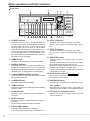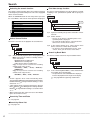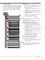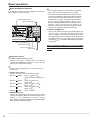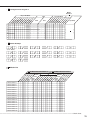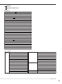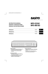
1
DIGITAL RECORDER
INSTALLER’S MANUAL
MODEL
DX-TL5000U
THIS INSTRUCTION MANUAL IS IMPORTANT TO YOU. PLEASE READ IT BEFORE USING YOUR DIGITAL RECORDER.
1
WARNING
RISK OF ELECTRIC SHOCK
DO NOT OPEN
WARNING: TO REDUCE THE RISK OF ELECTRIC SHOCK,
DO NOT REMOVE COVER (OR BACK)
NO USER-SERVICEABLE PARTS INSIDE
REFER SERVICING TO QUALIFIED SERVICE PERSONNEL.
The lightning flash with arrowhead symbol, within
an equilateral triangle, is intended to alert the user
to the presence of uninsulated “dangerous voltage”
within the product’s enclosure that may be of
sufficient magnitude to constitute a risk of electric
shock.
The exclamation point within an equilateral triangle
is intended to alert the user to the presence of
important operating and maintenance (servicing)
instructions in the literature accompanying the
appliance.
WARNING:
TO PREVENT FIRE OR SHOCK HAZARD, DO NOT EXPOSE THIS APPLIANCE TO RAIN OR
MOISTURE.
CAUTION:
TO PREVENT ELECTRIC SHOCK DO NOT USE THIS (POLARIZED) PLUG WITH AN
EXTENSION CORD, RECEPTACLE OR OTHER OUTLET UNLESS THE BLADES CAN BE
FULLY INSERTED TO PREVENT BLADE EXPOSURE.
••••••••••••••••••••••••••••••••••••••••••••••••••••••••••••••••••••••••••••••••••••••••••••••••••••••••••••••••••••••••••••••••••••••••••••••••••••••••••
i
AVERTISSEMENT
DANGER D’ÉLECTROCUTION
NE PAS OUVRIR
AVERTISSEMENT: POUR ÉLIMINER TOUT RISQUE D’ÉLECTROCUTION, NE PAS OUVRIR LE COUVERCLE
(OU LA PARTIE ARRIÈRE). AUCUNE PIECE
RÉPARABLE PAR L’UTILISATEUR NE SE
TROUVE À L’INTÉRIEUR.
POUR TOUTE INTERVENTION D’ENTRETIEN
OU DE RÉPARATION SE CONFIER AUX TECHNICIENS QUALIFIÉS.
La flèche symbolisant l’éclair dans un triangle équilateral
a pour objet de tirer l’attention de l’utilisateur sur le fait,
qu’il y a des “tensions dangereuses” non-isolées à
l’intérieur de l’enceinte du produit qui peuvent être
suffisamment importantes pour conduire au risque
d’électrocution.
Le point d’exclamation au sein d’un triangle équilateral a
pour objet de tirer l’attention de l’utilisateur sur le fait qu’il
y a des instructions de mise en service et d’entretien (de
réparation) dans les fiches descriptives de l’appareil qui
doivent obligatoirement être respectées.
AVERTISSEMENT:
AFIN D’ÉVITER TOUT RISQUE D’INCENDIE OU D’ÉLECTROCUTION, NE PAS EXPOSER CET
APPAREIL À LA PLUIE NI À L’HUMIDITÉ.
ATTENTION:
POUR PRÉVENIR LES CHOCS ÉLECTRIQUES NE PAS UTILISER CETTE FICHE POLARISÉE
AVEC UN PROLONGATEUR, UNE PRISE DE COURANT OU UNE AUTRE SORTIE DE
COURANT, SAUF SI LES LAMES PEUVENT ÊTRE INSÉRÉES À FOND SANS EN LAISSER
AUCUNE PARTIE À DÉCOUVERT.
••••••••••••••••••••••••••••••••••••••••••••••••••••••••••••••••••••••••••••••••••••••••••••••••••••••••••••••••••••••••••••••••••••••••••••• Beginning
ii
Important safeguards
PLEASE READ ALL THESE INSTRUCTIONS REGARDING YOUR RECORDER AND RETAIN FOR FUTURE
REFERENCE. FOLLOW ALL WARNINGS AND INSTRUCTIONS MARKED ON THE RECORDER.
1. Read Instructions
All the safety and operating instructions should be
read before the appliance is operated.
2. Retain Instructions
The safety and operating instructions should be retained for future reference.
3. Heed Warnings
All warnings on the appliance and in the operating
instructions should be adhered to.
4. Follow Instructions
All operating and use instructions should be followed.
5. Cleaning
Unplug this product from the wall outlet before cleaning. Do not use liquid or aerosol cleaners. Use a
damp cloth for cleaning.
6. Attachments
Do not use attachments not recommended by the
product manufacturer as they may cause
hazards.
7. Water and Moisture
Do not use this product near water – for example,
near a bath tub, wash bowl, kitchen sink, or laundry
tub, in a wet basement, or near a swimming pool,
and the like.
8. Accessories
Do not place the product on an unstable cart, stand,
tripod, bracket, or table. The product may fall, causing serious injury. Any mounting of the appliance
should follow the manufacturer’s instructions, and
should use a mounting accessory recommended by
the manufacturer.
An appliance and cart combination should be moved
with care. Quick stops, excessive force, and uneven
surfaces may cause the appliance and cart combination to overturn.
9. Ventilation
Slots and openings in the cabinet are provided for
ventilation and to ensure reliable operation of the
product and to protect it from overheating, and these
openings must not be blocked or covered. This product should never be placed near or over a radiator or
heat register. This product should not be placed in
a built-in installation such as a bookcase or rack unless proper ventilation is provided or the manufacturer’s instructions have been adhered to.
10.Power Sources
This product should be operated only from the type
of power source indicated on the marking label. For
products intended to operate from battery power,
other sources, refer to the operating instructions.
11. Grounding or Polarization
This product is equipped with a 3-wire groundingtype plug, a plug having a third (grounding) pin. This
plug will only fit into a grounding-type power outlet.
This is a safety feature. If you are unable to insert
the plug into the outlet, contact your electrician to
replace your obsolete outlet. Do not defeat the safety
purpose of the grounding-type plug.
12.Power-Cord Protection
Power-supply cords should be routed so that they
are not likely to be walked on or pinched by items
placed upon or against them, paying particular attention to cord at plugs, convenience receptacles,
and the point where they exit from the appliance.
13.Lightning
For added protection for this product receiver during
a lightning storm, or when it is left unattended and
unused for long periods of time, unplug it from the
wall outlet. This will prevent damage to the product
due to lightning and power-line surges.
14.Overloading
Do not overload wall outlets and extension cords as
this can result in a risk of fire or electric shock.
15.Object and Liquid Entry
Never spill liquid of any kind on the product.
••••••••••••••••••••••••••••••••••••••••••••••••••••••••••••••••••••••••••••••••••••••••••••••••••••••••••••••••••••••••••••••••••••••••••••••••••••••••••
iii
16.Servicing
Do not attempt to service this product yourself as
opening or removing covers may expose you to dangerous voltage or other hazards. Refer all servicing
to qualified service personnel.
17.Damage requiring Service
Unplug this product from the wall outlet and refer servicing to qualified service personnel under the following conditions:
(a) When the power-supply cord or plug is damaged.
(b) If liquid has been spilled, or objects have fallen
into the product.
(c) If the product has been exposed to rain or water.
(d) If the product does not operate normally by following the operating instructions. Adjust only
those controls that are covered by the operating
instructions as an improper adjustment of other
controls may result in damage and will often require extensive work by a qualified technician to
restore the product to its normal operation.
(e) If the product has been dropped or the cabinet
has been damaged.
(f) When the product exhibits a distinct change in
performance, this indicates a need for service.
18.Replacement Parts
When replacement parts are required, be sure the
service technician has used replacement parts
specified by the manufacturer or have the same
characteristics as the original part. Unauthorized
substitutions may result in fire, electric shock or other
hazards.
19.Safety Check
Upon completion of any service or repairs to this
product, ask the service technician to perform safety
checks to determine that the product is in safe operating conditions.
20.Heat
The product should be situated away from heat
sources such as radiators, heat registers, stoves,
or other products (including amplifiers) that product
heat.
NOTE
This equipment has been tested and found to comply with the limits for a Class A digital device, pursuant
to Part 15 of the FCC Rules. These limits are designed to provide reasonable protection against harmful
interference when the equipment is operated in a commercial environment. This equipment generates,
uses, and can radiate radio frequency energy and, if not installed and used in accordance with the instruction manual, may cause harmful interference to radio communications. Operation of this equipment in a
residential area is likely to cause harmful interference in which case the user will be required to correct the
interference at his own expense. Changes or modifications not expressly approved by the party responsible for compliance could void the user's authority to operate the equipment.
NOTE
THIS CLASS A DIGITAL APPARATUS COMPLIES WITH CANADIAN ICES-003.
CET APPAREIL NUMÉRIQUE DE LA CLASSE A EST CONFORME À LA NORME NMB-003 DU CANADA.
••••••••••••••••••••••••••••••••••••••••••••••••••••••••••••••••••••••••••••••••••••••••••••••••••••••••••••••••••••••••••••••••••••••••••••• Beginning
iv
Caution and care
HEAVY OBJECTS SHOULD NEVER BE PLACED ON THE UNIT (E.G., MONITOR)
NEVER TOUCH OR INSERT ANY OBJECT INSIDE THE UNIT
Touching the inside of the cabinet or inserting foreign objects of any kind through the disc loading slot or ventilation holes not
only creates a safety hazard but can also cause extensive damage.
PROTECT THE POWER CORD
Damage to the power cord may cause fire or shock hazard. If the power cord is damaged, turn OFF the MAIN switch and
carefully unplug the cord by holding the main plug.
If this unit is moved with the power on status, the built-in HDD may be damaged. Confirm that more than one minute have
passed since the power cord and the connecting cords were disconnected, then move this unit. Make sure to take the disc out
and close the disc loading slot.
UNPLUG THE POWER CORD DURING A LONG ABSENCE
Turn off the power and unplug the power cord during a long absence.
MAINTAIN GOOD VENTILATION
Do not obstruct the many ventilation holes on the unit. For maximum ventilation, leave some space around the unit and place
the unit on a hard level surface only, and ensure it is not covered during use. Heavy objects should never be placed on the unit.
WHEN NOT IN USE
When not in use, always eject the disc and turn OFF the MAIN switch.
CABINET CARE
Never use petroleum-based cleaners. Clean with a soft cloth moistened with soap and water and wipe dry.
PVC cables or leads should not be left in contact with the cabinet surface for long periods.
INSTALLATION LOCATION
For excellent performance and lasting reliability install in a location that is:1. Well ventilated, out of direct sunlight and away from direct heat.
2. A solid vibration-free surface.
3. Free from high humidity, excessive dust and away from magnetic fields.
4. Please ensure that the ventilation fan located on the unit’s back panel is not blocked.
UNSUITABLE LOCATIONS
Placing the unit in the following places might shorten the product life:
• Extremely cold places, such as refrigerated warehouses and ice houses
• Places where excessive hydrogen sulfide is likely to be generated, such as hot-springs areas
• Places or locations with salt air environment.
NO OBJECTS FILLED WITH LIQUIDS, SUCH AS VASES, SHALL BE PLACED ON THE APPARATUS.
DO NOT PLACE HEAVY OBJECT ON THIS UNIT.
DO NOT STEP ONTO THIS UNIT.
DO NOT PLACE ANY OBJECTS IN FRONT OF THE DISC LOADING SLOT.
The unit may drop or fall by losing its balance. It may cause injury or failure of the unit.
WARNING:
TO PREVENT FIRE OR SHOCK HAZARD, DO NOT EXPOSE THIS APPARATUS TO RAIN OR MOISTURE.
THIS APPARATUS MUST BE GROUNDED.
••••••••••••••••••••••••••••••••••••••••••••••••••••••••••••••••••••••••••••••••••••••••••••••••••••••••••••••••••••••••••••••••••••••••••••••••••••••••••
2
WARNING:
The supplied power cord is used for 120 V only. Never connect to any outlet or power supply having a
different voltage or frequency.
Notice about construction of the surveillance system using this unit
• This unit can be controlled by the external devices via RS-232C terminal or LAN terminal. This unit can also be used to
control external devices via external terminal, RS-422/485, or RS-232C terminal. Owning to these functions, this unit
flexibly applies to the high grade security system, but the whole surveillance system may be affected by the malfunction
of this unit or the external devices depending on the setting contents of this unit, or the connection or combination
between the external devices.
• When configuring a surveillance system using this unit, it is recommended to confirm first that this unit operates normally
with the other devices connected.
• It is recommended to copy or back up the important recorded contents.
• Damages rising out of any operational error of the surveillance system or loss of the recorded data or any other damages
because of any user malfunction of this unit are not covered.
There may be cases when the unit’s built-in MOTION DETECTION function does not operate properly due to external
condition or video input signal or other factors.
The user will not be indemnified for problems (e.g., recording failure or playback failure) that occur with either the unit or a
connected device during operation. It is recommended that backups of important recordings are made regularly as a precaution against possible breakdowns and accidents.
Recordable time and product warranty
Continuous recordable time and the estimated time displayed on the menu screen is the continuous recordable time when
operating this unit and is not the product warranty period. Furthermore, it is not the period that guarantees life time at the unit.
• This unit uses a built-in hard disk, which is a precision device. Please handle this unit with sufficient care.
• Do not subject this unit to vibrations or shocks. This may cause trouble specially when the power of the unit is turned on
or when the hard disk is being accessed, and sufficient care is required.
• Do not disconnect the power plug while the power of the unit is turned on or while recording or playing.
• For early detection of faults, we recommend that you request inspection once a year.
The hard disk and cooling fan are not permanent items and will need replacing with time. When operated in an ambient
temperature of 25 °C, it is recommended that both of the hard disk and fan are replaced every 30,000 hours.
(This figure is only a guide, and should not be taken as a guaranteed lifespan of the products. Use the <Elapsed Operating
Time> (System Menu Service Info) as a guide to perform checkups.)
••••••••••••••••••••••••••••••••••••••••••••••••••••••••••••••••••••••••••••••••••••••••••••••••••••••••••••••••••••••••••••••••••••••••••••• Beginning
3
Caution and care (continued)
DISCLAIMER
In any event, Mitsubishi assumes no responsibility or reliability for the following:
1. Disassembly, repair, or alteration of this unit by user or installer.
2. Failure or breakdown in or damage to this unit resulting from misuse or careless handling by user or installer.
3. Inconvenience or damages arising out of inability to display or record images due to any reason or cause other than
breakdown or failure in this unit.
4. Failure in this unit due to combination with other equipment manufactured by a third party or inconvenience or damages
resulting from such failure.
5. Inconvenience, damages, or claims arising out of breakdown in this unit or loss of recorded video data due to replacement of the built-in HDD by user or installer.
6. Inconvenience or damages arising out of breakdown in this unit or inability to display or record images due to natural
disaster including earthquake and storm.
7. Inconvenience, damages, or claims arising out of breakdown in this unit or loss of recorded video data due to impact or
vibration to the built-in HDD or an environmental factor such as temperature at the installation site.
8. Demand for damages or other claim of infringement of privacy if the images monitored or recorded by user become
public or are used for any purpose other than surveillance for whatever reason.
INSTALLATION LOCATION AND HANDLING
•
•
•
•
Place this unit horizontally and in a stable place. If this unit is not placed correctly and used in an unstable place, the unit
may be damaged such as removal of the DVD/CD disc.
Do not place this unit close to other electronic or magnetic equipment. This will avoid video and audio distortion.
When a monitor and this unit are placed vertically, the pictures may be distorted or DVD/CD disc may not be ejected.
Do not let stick your hands into the disc loading slot. You may get your hand caught in the slot and may got injured. If you get
your hand caught, do not get out of the slot by force. Contact your dealer after turning off the power and disconnecting the
plug.
DVD/CD DISC
• Do not use the disc cracked, deformed or repaired with adhesive. The disc may fly into pieces and cause injury.
• Do not touch the playback surface when holding the disc.
• When dew condensation occurs on the disc, wipe the surface off before use.
• Dirt such as fingerprints or dust causes the deterioration of the picture quality and audio quality. Gently wipe the DVD/CD
disc from the center to the outside with a soft cloth.
• When the disc is very dirty, soak a soft cloth with water and screw water of it, wipe off the dirt lightly, then wipe with a dry
cloth.
• Do not use solvent such as benzine and thinner, a record cleaner, and static-stopper. They may damage the disc.
• Do not use the disc described below. They may damage the disk itself or this unit.
Discs on which a piece of paper or sticker is put, or a disk damaged.
Discs which the label is peeled or a disk with oozing.
Discs cracked, deformed, or repaired with adhesive.
• Store the disc in the specified casing, avoiding the following places.
Places where it will be subjected to direct sunlight.
Places with excessive dust.
Places where it will be subjected to high temperatures or high humidity.
• DVD movie (cinema) or personal recorded picture cannot be played back on this unit. Only the pictures recorded on this unit
can be played back.
MAINTENANCE OF THE LENS FOR RECORDING/PLAYBACK (LASER PICKUP)
• When any dust adheres on the lens for recording/playback, the image may be distorted or the audio may skip. Also normal
recording or playback may not work. Ask your dealer how to correct this problem.
Be careful, do not use the commercial lens cleaning disk, they may damage the lens.
••••••••••••••••••••••••••••••••••••••••••••••••••••••••••••••••••••••••••••••••••••••••••••••••••••••••••••••••••••••••••••••••••••••••••••••••••••••••••
4
Note
Thank you for purchasing Mitsubishi digital recorder DX-TL5000U (hereinafter referred to as “Product”). Before using this
Product, please be sure to read the Software License Agreement on page 7 of the user’s manual with regard to the software
contained in this Product (hereinafter referred to as “Licensed Software”). By using this Product, you are agreeing to be
bound by the terms and conditions of the following Software License Agreement.
This Product contains software programs that are covered by GNU General Public License or GNU Lesser General Public
License. Such software programs are excluded from Licensed Software and not covered by the following Software License
Agreement. For the terms and conditions for use of the software programs covered by GNU General Public License or GNU
Lesser General Public License, please see “Notice about software to which GNU GPL/LGPL is applied”*.
In addition, this Product contains “Apache” and “OpenSSL (including “Original SSLeay” library).” These software programs
are also excluded from Licensed Software and not covered by the following Software License Agreement. For the terms and
conditions for use of these software programs, please see “Notice about Apache software”* and “Notice about OpenSSL
software”*.
Each of “Berkeley Database,” “agetty,” “expat,” and “zlib” contained in this Product is other open source software. These
software programs are excluded from Licensed Software and not covered by the following Software License Agreement. For
the terms and conditions for use of these software programs, please see “Notice about other open source software”*.
*
The documents of “Notice about software to which GNU GPL/LGPL is applied,” “Notice about Apache software,” “Notice about
OpenSSL software,” and “Notice about other open source software” are contained (in the format of electronic files as
notice_GPL_LGPL_ja.pdf, notice_Apache_ja.pdf, notice_OpenSSL_ja.pdf, and notice_other_ja.pdf) in the “OpenSoft_License”
folder in the accessory CD supplied with this Product.
••••••••••••••••••••••••••••••••••••••••••••••••••••••••••••••••••••••••••••••••••••••••••••••••••••••••••••••••••••••••••••••••••••••••••••• Beginning
5
Features
DX-TL5000U is a digital recorder that is equipped with HDD as its main memory and 16ch triplex multiplexer.
Addition to these features, this system has a very sophisticated video signal and data processing technique that
provides high quality picture, stable operation and reliability. The graphical user interface and pointing devices
make the operation very easy and comfortable in live monitoring and also in the handling of data from recording to
export. The system offers excellent performance and has features to suit many video surveillance applications.
Refresh rates of 960pps*/system
Thanks to the newly developed multiplexing circuit, every camera can be viewed at 60 pps refresh rate in all screen
formats.
pps* : picture per second
Triplex
User can view live and playback images on the same monitor in all screen multi-split layouts without disrupting
recording.
Dual Multiplexer Outputs
The DX-TL5000U has two video outputs (Output A / B), and both of the outputs can show single-screen, 4, 9, 10,
13 and 16 split-screen, Switched Cameras, Alarmed Camera in live mode and Recorded pictures. On Screen
Menu are shown only on monitor Output A. It is also possible to view playback pictures of different cameras at the
same time with these two video outputs.
Covert Camera Function
It is possible to hide pictures of selected cameras that are installed in sensitive areas and should only be viewed by
authorized personnel. It can be switched by <Multiplexer Setting>.
GUI
MENU, GUI (Graphical User Interface), guides the operators to their desired menu pages quickly. If the users need
additional information on MENU functions, just press the HELP key and instructions will appear on screen. The
menu supports English, French, and Spanish. Function keys on the front panel or USB mouse can operate the
menu on the DX-TL5000U.
Recording rate up to 240 pps/system
Because of the new recording circuit and compression chip, the maximum recording speed is 240 pps in total, this
means that the system can record pictures with speed of up to 15 pps on all 16 channels. With this speed recorded
pictures are seen by the eye as real-time.
JPEG2000
The system uses JPEG2000 compression. JPEG2000 is the standard and ideal compression method for still
pictures. Because pictures are compressed to a user defined file size one by one, the estimated recording time
calculated by the system automatically is very accurate. Special playback search functions and transmission over
network also benefit from this compression method. File sizes for each picture quality are minimized to improve
storage efficiency over previous models.
Individual Recording Setting
Recording speed and picture quality (picture file size) can be set for each camera individually, it is also possible to
set alarm recording setting in addition to normal recording setting. By adjusting the recording speed and picture
quality, it is possible to use HDD storage space efficiently.
Audio Recording
4ch audio inputs are featured. The audio such as cash register operation and conversation with customers can be
recorded clearly together with the monitoring pictures.
Copy
The easiest way for users to make a copy of recorded picture data is to use the built in CD/DVD Drive on the DXTL5000U. Or, they can also use other digital media such as HDD, DVD(-R/RW)*, CD-R/RW* USB Memory etc…
through Serial Bus Interface. It is also possible to connect SCSI devices through the optional SCSI interface or
NAS (Network Attached Storage) through network.
DVD(-R/RW), CD-R/RW* : only one drive can be used (including built-in CD/DVD drive)
Cascading Connection
Cascading connection allows to users to view pictures and to hear sounds from multiple DX-TL5000U by operating
via operations from the master unit.
••••••••••••••••••••••••••••••••••••••••••••••••••••••••••••••••••••••••••••••••••••••••••••••••••••••••••••••••••••••••••••••••••••••••••••••••••••••••••
6
Microsoft is either registered trademarks or trademarks of Microsoft Corporation in the United States
and/or other countries.
All other company and product names appearing herein are the property of their respective owners.
••••••••••••••••••••••••••••••••••••••••••••••••••••••••••••••••••••••••••••••••••••••••••••••••••••••••••••••••••••••••••••••••••••••••••••• Beginning
7
Contents
Important safeguards ........................................... i-iv
Caution and care ................................................... 2-4
Note ........................................................................... 5
Features ................................................................ 6, 7
Contents ................................................................ 8, 9
Flowchart .......................................................... 10, 11
PTZ Control ............................................................. 50
PTZ control using the menu .............................................. 50
PTZ control using the front panel buttons ......................... 50
<Setup Menu>
Recording .......................................................... 51-55
Front view ................................................................... 12, 13
Loading/Ejecting a DVD disc or CD .................................. 13
Front view (inside of the door) .......................................... 14
Rear view .................................................................... 15, 16
Settings concerning normal recording and
alarm recording ................................................................. 51
Pre-alarm recording .................................................... 51
Set Recording Pattern A (Normal/Timer) to D (Timer) .. 51-53
Alarm Input .................................................................. 53
Emergency Recording Setup ...................................... 54, 55
Emergency recording .................................................. 54
Long pre-alarm recording ...................................... 54, 55
Audio Recording Setup ..................................................... 55
Connections ...................................................... 17-25
Timer ................................................................. 56, 57
Connecting to CCTV camera, monitor, and sensor .......... 17
Alarm recording connection .............................................. 18
Cascade connection ......................................................... 19
Attaching or removing the HDD ................................... 20-23
Precautions for attaching or removing the HDD ......... 20
When removing a HDD ............................................... 21
When attaching a HDD ......................................... 22, 23
Clamping the cables ......................................................... 24
Connecting to an analogue video cassette recorder ......... 24
Optional items ................................................................... 25
Recommended items ........................................................ 25
Attaching the optional board ............................................. 25
Overlapped timer settings ........................................... 57
Flowchart for connection and settings ........................ 10, 11
Major operations and their functions .............. 12-16
How to set the menus ....................................... 26-29
Setting the menus ........................................................ 26-28
Setting the menu using a mouse ................................ 26
Setting a mouse ..................................................... 26
Setting a menu with a mouse ................................. 26
Setting the menu using the front panel buttons .......... 26
Displaying a menu screen ........................................... 27
Closing a menu screen ............................................... 27
Selecting an item ........................................................ 27
Inputting numbers ....................................................... 28
Setting parameters ...................................................... 28
Symbols in the menus ....................................................... 29
Setup Wizard .................................................... 30, 31
Setup Wizard .............................................................. 30, 31
Menu chart ......................................................... 32-41
Menu chart ................................................................... 32-41
User Menu ............................................................ 32, 33
Setup Menu ............................................................ 34-38
System Menu ......................................................... 39-41
<User Menu>
Search ............................................................... 42, 43
Selecting the search function ............................................ 42
Select Source Device ........................................................ 42
Search by Time and Date ................................................. 42
Search by Alarm List ......................................................... 42
Find data storage location ................................................. 42
Search by Book Mark ........................................................ 42
Search by Motion .............................................................. 43
Copy ................................................................... 44-47
Motion Det ......................................................... 58, 59
Set Motion Detection Pattern A/Set Motion Detection
Pattern B ..................................................................... 58, 59
System ............................................................... 60-71
Time/Date Setting ............................................................. 60
Menu Language Selection ................................................ 60
Rear Terminal Setting .................................................. 60, 61
Mode Out Settings ................................................ 60, 61
Call Out Settings ......................................................... 61
Key Sound .................................................................. 61
Buzzer ......................................................................... 61
Password Setting ........................................................ 62, 63
SIMPLE LOCK ............................................................ 62
Activating the simple lock ....................................... 62
Releasing the simple lock ...................................... 62
PASSWORD LOCK ............................................... 62, 63
Using “Operation control” of PASSWORD LOCK
(level 1 to 3) ........................................................... 62
Registering the PASSWORD ................................ 62, 63
Activating the PASSWORD LOCK .............................. 63
Releasing the PASSWORD LOCK .............................. 63
Changing the PASSWORD ......................................... 63
Changing the lock mode from PASSWORD LOCK
to SIMPLE LOCK ........................................................ 63
Multiplexer function related button operations/
operation table ............................................................ 64, 65
Camera number button operations ............................. 64
SPLIT buttons operations ............................................ 64
SEQUENCE button operations ................................... 64
DIGITAL ZOOM button operations .............................. 64
The function of the SPLIT, SEQUENCE, DIGITAL
ZOOM, and camera number buttons .......................... 65
Multiplexer Setting ....................................................... 66-68
Output A Settings ........................................................ 66
Output B Settings ........................................................ 67
Alarm Display Setting .................................................. 68
Covert Camera Setting ............................................... 68
On Screen Display Setting .......................................... 69, 70
On Screen Information ................................................ 69
Camera Title ................................................................ 69
Recorder Title .............................................................. 70
Monitor Output Adjust ................................................. 70
Audio Setting ..................................................................... 70
Reset to Factory Setting ................................................... 71
Copy Data to Copy 1 Drive/Set Copy 1 Drive ................... 44
Copy Data to Copy 2 Drive/Set Copy 2 Drive ............. 44, 45
Copying the data of this unit to a video cassette .............. 45
Playback software ....................................................... 46, 47
Menu Data ............................................................... 72
Information/Audio .................................................. 48
Load Menu Data ............................................................... 72
Save Menu Data ............................................................... 72
Information ........................................................................ 48
Audio ................................................................................. 48
Protect Data ............................................................ 49
Option ...................................................................... 73
XGA Monitor Settings ........................................................ 73
Protect Data ...................................................................... 49
••••••••••••••••••••••••••••••••••••••••••••••••••••••••••••••••••••••••••••••••••••••••••••••••••••••••••••••••••••••••••••••••••••••••••••••••••••••••••
8
<System Menu>
COM/LAN ........................................................... 74-76
RS-232C Setting ............................................................... 74
RS-485 Cascade Setting .................................................. 74
LAN B (Communication) Setting ....................................... 75
LAN A (NAS) Setting ......................................................... 76
PTZ Setting ............................................................. 77
PTZ Camera Configuration ............................................... 77
Configuration Check List ................................................... 77
Service Info ............................................................. 78
System Log List ................................................................ 78
Elapsed Operating Time ................................................... 78
Disk Information ................................................................ 78
Restore .................................................................... 79
Restore Data to Main HDD from Drive 1/2/
Export Drive 1/2 Configuration .......................................... 79
Memory .............................................................. 80-83
Communications by Web Browser .............. 101-109
Communications by Web Browser .................................. 101
The personal computer product requirements .......... 101
Connections .............................................................. 101
Login ....................................................................... 101, 102
Main Menu ............................................................... 102-109
Live Monitoring .......................................................... 103
Playback ........................................................... 104, 105
Time Search ......................................................... 104
Alarm List Search ................................................. 105
Image Search ....................................................... 105
Configuration Menu ............................................ 105-108
User Registration .......................................... 105-106
Recorder Title & Camera Titles ............................ 107
E-mail Setup ......................................................... 107
NAS Setup ........................................................... 108
Clock Setup .......................................................... 108
Logout ....................................................................... 109
Change Login User ................................................... 109
Add/Remove HDD Device .......................................... 80, 81
Notes for using the external device ........................ 81
Attaching the HDD and setting the ID number ....... 81
The order of recording/playback when internal and
external HDDs are registered as the main device .. 81
Add/Remove DVD/CD Drive ............................................. 82
Data Management Setting for Main Memory .................... 82
Recording Data Readout Setting ...................................... 83
Recording time table .................................... 110, 111
Data Clear ............................................................... 84
Check sheet ................................................... 116-135
Main Storage Memory ....................................................... 84
Copy 1/Copy 2 .................................................................. 84
Setup Menu .............................................................. 116-130
System Menu ........................................................... 130-135
Other convenient functions ............................. 85-89
Glossary ........................................................ 136, 137
Cascade ............................................................................ 85
Various playback functions .......................................... 86, 87
Playing still frames ...................................................... 86
Shuttle viewing/direct shuttle viewing ......................... 86
Shuttle hold ................................................................. 86
Frame-by-frame playback ........................................... 86
Reverse playback ....................................................... 86
High-speed fast-forward/high-speed rewind ............... 86
Changing playback intervals ....................................... 87
Simultaneous playback during recording .................... 87
Playback the latest recorded contents ........................ 87
Triplex playback .......................................................... 87
Registering the picture ...................................................... 88
Registering a book mark ............................................. 88
Picture copy ................................................................ 88
Functions of the unit in case of power failure .................... 89
Power failure compensation circuit ............................. 89
Power failure reset recording ...................................... 89
Log function when power failure occurs while the unit is
in operation or the MAIN switch on the rear of the unit is
turned OFF .................................................................. 89
RESET button ................................................................... 89
Glossary .......................................................................... 136
Relation of recording operation to the number of
cameras and recording rate settings ............................... 137
Operation examples .......................................... 90-95
Operation example 1 ......................................................... 90
Operation example 2 ......................................................... 91
Operation example 3 ................................................... 92, 93
Operation example 4 ................................................... 94, 95
Basic operations ............................................. 96-100
Basic multiplexer functions ............................................... 96
Multiplexer buttons ...................................................... 96
Basic manual recording .................................................... 97
Setting the recording rate and picture grade for normal
recording ..................................................................... 97
Basic playback .................................................................. 98
Basic search ............................................................. 99, 100
Search by Time and Date ........................................... 99
Search by Alarm List ................................................. 100
Continuous recording time table .............................. 110, 111
Without audio recording ....................................... 110
With audio recording ............................................. 111
Troubleshooting ........................................... 112, 113
Warnings and CALL OUT output ................ 114, 115
Warnings and their appropriate countermeasures ... 114, 115
Specifications ....................................................... 138
How to read this manual
• Viewing displays
(Refer to this information when operating):
Reference information concerning operation
(Caution required):
Cautionary items concerning operation
(See reference page):
Reference item and page number
• Finding desired information
There is a “Contents” at the beginning of this manual.
In addition, reference pages are indicated throughout
this manual.
• Troubleshooting
Read Troubleshooting (pages 112, 113) for possible
remedies to the problem.
• Menu settings
See Check list (pages 116-135) for available setting
parameters for each menu.
••••••••••••••••••••••••••••••••••••••••••••••••••••••••••••••••••••••••••••••••••••••••••••••••••••••••••••••••••••••••••••••••••••••••••••• Beginning
9
Flowchart
Flowchart for connection and settings
This is a flowchart of the example operation:
Making connections of the terminal on the rear panel Setting the alarm area in the main device Making the
initial settings Making an alarm recording with timer recording Searching recorded data using the alarm list
Playback the recorded data Copying the data to a copy device.
Connections
• Connections for camera, monitor, and sensor.
See “ Connecting to CCTV camera, monitor,
and sensor” on page 17.
• Connection for the alarm recording.
See “ Alarm recording connection” on page
18 and “ Rear view” on pages 15, 16.
Connections
• Connections for camera, monitor, and sensor.
See “ Connecting to CCTV camera, monitor,
and sensor” on page 17.
• Connection for the alarm recording.
See “ Alarm recording connection” on page
18 and “ Rear view” on pages 15, 16.
Boot-up the unit
Boot-up the unit
When not executing Setup Wizard:
When executing Setup Wizard:
See “ Setup Wizard” on pages 30, 31.
See “ Setup Wizard” on pages 30, 31.
Only when the unit is turned on for the first time, the
<Setup Wizard> screen is displayed automatically. It
is not displayed next time.
Only when the unit is turned on for the first time, the
<Setup Wizard> screen is displayed automatically. It
is not displayed next time.
• Set the present time and HDD settings in each menu
manually. (“ Time/Date Setting” on page 60. Set the
present time.“ Data Management Setting for Main
Memory” on page 82. Set the alarm area.)
• The language, present time, HDD configuration, and
recording settings are set automatically by following
the instructions in the menu.
Recording
Making the initial menu settings
• Setting the present time display mode.
See “
On Screen Information” on page 69.
• Setting the audio recording.
See “ Audio Recording Setup” on page 55 and
“ Continuous recording time table” on pages 110, 111.
Making the HDD settings
• Setting the repeat recording.
See “ Data Management Setting for Main
Memory” on page 82.
• Setting the remaining HDD capacity.
See “Low Memory Alarm Setting” on pages 60
and 61.
• Setting the CALL OUT.
See “
Call Out Settings” on pages 60 and 61.
• Setting the buzzer.
See “
Buzzer” on page 61.
Making the multiplexer settings
• Making the split screen settings.
See “
Multiplexer Setting” on pages 66, 67.
• Making the sequence setting.
See “
Multiplexer Setting” on pages 66, 67.
Setting other various functions
• Setting the camera title/recorder title.
See “ Camera Title” and “
page 69, 70.
Recorder Title” on
• Setting the display mode.
See “
On Screen Information” on page 69.
• Setting the output signal of the unit status.
See “
Mode Out Settings” on pages 60 and
61.
••••••••••••••••••••••••••••••••••••••••••••••••••••••••••••••••••••••••••••••••••••••••••••••••••••••••••••••••••••••••••••••••••••••••••••••••••••••••••
10
Setting the motion detection
•
•
•
•
Selecting the camera number.
Setting the detection areas.
Setting the sensitivity.
Setting the minimum number of dots for starting the
motion detection operation.
• Setting the detection interval.
Copy the data
• Setting the copy device.
See “ Add/Remove HDD Device” or “
Remove DVD/CD Drive” on pages 80-82.
Add/
• Setting the copy function.
See “ Copy Data to Copy 1 Drive” or “ Copy
Data to Copy 2 Drive” on pages 44, 45.
See “Motion Det” on pages 58, 59.
Setting the timer recording
• Setting the normal/alarm recording or pre-alarm
recording.
• Setting the recording rate/picture grade for normal
recording.
• Setting the recording rate/picture grade for alarm
recording.
• Setting the motion detection recording.
• Selecting the camera selection during the alarm
recording and trigger for alarm recording.
• Setting the alarm recording time.
• Setting the pre-alarm recording time.
• Setting the PTZ camera preset.
See “ Set Recording Pattern A
(Normal/Timer) to D (Timer)” on pages 5153.
• Setting the timer program.
• Setting the holiday.
• Selecting the timer program number.
• Making the timer recording settings.
• Selecting the day of the week.
• Selecting the start time.
• Selecting the end time.
• Selecting the program mode.
• Selecting the motion detection mode.
(• Selecting the special day of the week.)
See “Timer” on pages 56, 57.
Timer recording is executed and completed
See “
Warnings and their appropriate
countermeasures” on pages 114, 115.
Searching the recorded data
• Setting the device to be searched.
See “
Select Source Device” on page 42.
• Setting the alarm list search.
See “
Search by Alarm List” on page 100.
The search is completed and the search result
is displayed
Playback the search result
• Selecting the camera number to be played back.
See “
Multiplexer Setting” on pages 66, 67.
• Selecting the split/sequence screen.
See “
Multiplexer Setting” on pages 66, 67.
• Playback the recorded data.
See “
Basic playback” on page 98.
• Selecting the playback speed.
See “
86, 87.
Various playback functions” on pages
••••••••••••••••••••••••••••••••••••••••••••••••••••••••••••••••••••••••••••••••••••••••••••••••••••••••••••••••••••••••••••••••••••••••••••• Beginning
11
Major operations and their functions
Front view
17
18
19
20
21
BUSY
PUSH
1
2
3 4 5 6 7 8 9 10 11
1. POWER indicator
Illuminates when the unit is ON (MAIN switch on
the rear is ON and the POWER button in the front
has been pressed.) Turns off when the unit is in
stand by mode (only rear switch is ON) or MAIN
switch on the rear is turned off. It takes about 1 or 2
minutes from pressing the POWER button to switch
the unit ON. When the unit is in operational transition such as boot-up, the indicator flashes and other
operations are not accepted.
2. REMOTE jack
Input connector for optional wired remote control.
3. ACCESS indicator
Illuminates during accessing to hard disk drive, or
peripheral recording devices. Press the POWER
button after the ACCESS indicator is turned off and
“POWER OFF” is displayed on the LCD display.
4. COM (COMMUNICATION) indicator
Illuminates when establishing the communication
with personal computer.
5. ALARM indicator
Illuminates during alarm recording.
6. TIMER indicator
Illuminates during timer recording or timer recording
stand-by mode.
7. LOCK indicator
Illuminates while simple lock or password lock is
turned on.
12
13 14 15 16
10. COPY 1 indicator
Illuminates while performing copy 1 operation.
Flashes when starting or ending the copy 1 operation.
11. COPY 2 indicator
Illuminates while performing copy 2 operation.
Flashes when starting or ending the copy 2 operation.
12. REC/STOP button
Starts recording. The button lights up during
recording.
When pressing the button for more than 2 seconds,
the recording stops and the light turns off.
When pressing this button for more than 2 seconds
during alarm recording, recording stops.
During timer recording, recording will not stop even
if the button is pressed.
13. SPLIT screen buttons (
, , , ,
)
Selects split screen to be displayed.
Used for the menu settings.
14. SEQUENCE button
Used to select and display the sequential screens.
TILT
button
When pressing the button during PTZ mode, the
angle of the camera adjusts in the upward direction.
15. PTZ (Pan, tilt, and zoom) button
Switches this unit to PTZ mode to control the PTZ
camera connected.
8. M-DET indicator
Illuminates when the motion detection function is
activated.
Flashes during motion detection recording.
9. PRE ALARM indicator
Illuminates during pre-alarm recording.
It also illuminates when pre-alarm recording is set.
••••••••••••••••••••••••••••••••••••••••••••••••••••••••••••••••••••••••••••••••••••••••••••••••••••••••••••••••••••••••••••••••••••••••••••••••••••••••••
12
Camera control buttons
21. Camera number buttons (1 to 16)
The following buttons control PTZ motion during PTZ
mode. This unit must be in single screen display.
FOCUS button
Displays the picture supplied from the camera connected. The number of the button corresponds to
that of the CAMERA IN connector on the rear panel.
The button of the displayed camera number lights
up.
Used for the preset function of the PTZ camera control.
Used for the menu settings.
Adjusts the focus of a camera. Press this button and
then turn JOG to the left (far) or right (near) to adjust
the focus.
M-DET DOT ON/OFF/M-DET AREA SET UP
(CAMERA NUMBER 9 and 13)
IRIS button
Used for setting the detection area of the motion
detection function.
CAMERA ZOOM button
Adjusts the camera zoom. Press this button and then
turn JOG to the left (wide) or right (tele) to adjust the
camera zoom.
Adjusts the iris of a camera. Press this button and
then turn JOG to the left (close) or right (open) to
adjust the iris.
PRESET button
Presets up to 16 viewing positions. Press this button
and then press the camera number button within 3
seconds to preset the points.
Loading/Ejecting a DVD disc or CD
•
Before using the disc, read the cautionary notes
described in the manual included with the disc.
step1.
• The disc loading tray opens.
AUTO PAN button
Activates auto pan of the camera connected.
(When loading the disc:)
step2-1. Place the disc into the tray.
• Make sure the disc is inserted properly with the
label side up.
16. OUTPUT A/B button
Switches the multiplexer output between A and B.
The light turns off when OUTPUT A is selected and
on when OUTPUT B is selected. It affects both, playback and search functions.
TILT
(When ejecting the disc:)
step2-2. Eject the disc from the tray.
step3.
Press the OPEN/CLOSE button again.
• The disc loading tray closes.
button
When pressing the button during PTZ mode, the
angle of the camera adjusts to the downward
direction.
•
Do not eject the disc while copying/restoring, saving/
loading menus, or immediately after inserting the
disc. The disc or the contained data may be
damaged.
•
Please use the disc which we recommend. When a
disc other than the recommended one is used, the
data may not be read or written correctly. Please
consult your dealer for recommended usable discs.
•
When using DVD-RW or CD-RW disc, initialize the
disc before using by <Data Clear> menu.
17. Disc loading slot
Accepts DVD disc or CD to copy/backup.
The supported discs are:
DVD-RW, DVD-R, CD-R, and CD-RW
OPEN/CLOSE
Press the OPEN/CLOSE button.
button
Opens or closes the disc loading slot.
BUSY indicator
Flashes or illuminates during recording or playback.
18. LCD display
Displays the present time and the status of the unit.
19. SHUTTLE ring
Adjusts the playback speed, and rewinds or forwards
the recorded pictures.
Pans the camera.
20. JOG dial
Forwards or rewinds the picture during playback
(frame-by-frame).
Uses for controlling PTZ cameras connected.
••••••••••••••••••••••••••••••••••••••••••••••••••••••••••••••••••••••••••••••••••••••••••••••••••••••••••••••••••••••••••••••••••••••••••••• Beginning
13
Major operations and their functions (continued)
Front view (inside of the door)
25 26 27 28
AUDIO OUT
22
23
24 29 30 31 32
22. POWER button
Turns on the unit (MAIN switch on the rear of this
unit must be ON). When the button is pressed again,
the unit switches to stand-by mode. The POWER
and other button operation are not accepted while
the POWER indicator is flashing.
23. ANALOGUE OUTPUT connectors
VIDEO OUT connector
Output connector for video signal (RCA pin).
AUDIO OUT connector
Output connector for audio signal (RCA pin).
24. SERIAL BUS port
Input and output port for the devices equipped with
SERIAL BUS connectors.
25. HELP button
Displays the help menu (for caution on use, operating method, and explanation on functions).
Used when the warning message is displayed.
This button can be used even while the menu screen
is displayed.
26. SET UP button
Displays the <User Menu>.
27. SEARCH button
Displays the <User Menu> with search menu
opened.
28. TIMER button
Sets the unit to timer recording/stand-by mode and
lights up the TIMER indicator. When pressing this
button for more than 2 seconds, timer recording/
stand-by mode is cancelled and the TIMER indicator
turns off.
29. LOCK button
33
30. TRIPLEX PB button
In split screen display, inserts the playback picture
of needed camera while also displaying the live picture from other camera.
31. BOOK MARK button
When pressing this button during frame still playback of the single screen display, the selection
screen appears and you can memorize the book
mark or copy the picture being displayed.
32. DIGITAL ZOOM button
Pressing this button in single screen display displays the screen in 100 % magnification (live or playback). Pressing the camera number button (11, 14,
15, or 16) moves the magnification centre point.
33. Operation buttons
STOP button
Stops playback.
PAUSE/JUMP TO END button
Switches the playback to still frame playback when
pressing this button during playback. Resumes
playback when pressing this button again. The
button lights up during still frame playback.
When pressed during shuttle playback, the set playback speed is maintained even when letting go of
the SHUTTLE ring. (Shuttle hold)
When pressed during the unit is in stop mode of
playback, the frame still picture around the end point
of the latest recording appears. (Jump to end)
REV. PLAY (REVERSE PLAY) button
Starts reverse playback. The button lights up during
reverse playback.
PLAY button
Starts playback. The button lights up during
playback.
Activates simple lock or password lock when pressing
SPEED (+ and –) button
while the MAIN switch (main power) on the rear panel
Switches the playback interval speed during noris turned on and lights up the LOCK indicator. Moreomal or reverse playback.
ver, the PASSWORD can be set on the <Password
Setting> (Setup Menu System Password Setting).
••••••••••••••••••••••••••••••••••••••••••••••••••••••••••••••••••••••••••••••••••••••••••••••••••••••••••••••••••••••••••••••••••••••••••••••••••••••••••
14
Rear view
3
4
8
5 67
9
10
AUDIO IN
IN
OUT
1
2
3
4
5
6
7
8
VIDEO
VIDEO
1
2
3
4
OPTION SLOT
Y/C
OUTPUT A OUTPUT B
CAMERA
OUT
AUDIO
CLAMPER
IN
OUT
9
10
11
12
13
14
15
16
OUT
IN
CASCADE
IN
AUDIO OUT
VIDEO CASCADE
SERIAL BUS SERIAL BUS
LAN-A
LAN-B
CLAMPER
OFF
ON
1
2
11 12
This is the main power switch. To use this unit, set
this switch to ON. Otherwise, the front power button will not turn the unit on/off.
2. AC power socket
Used to connect the power cord. Earth terminal is
used for safety. Use the 100 to 240 V plug with
ground terminal.
•
10 100
COM
RS485
OUT
10
RS485
IN
PTZ
100-240V
1. MAIN switch
•
STORAGE
ALARM IN
CLOCK ADJ
CLOCK ADJ OUT
REC
REC STOP
EMERGENCY
RESERVED
MODE OUT 1 +
MODE OUT 1 —
MODE OUT 2 +
MODE OUT 2 —
MODE OUT 3 +
MODE OUT 3 —
MODE OUT 4 +
MODE OUT 4 —
CALL OUT +
CALL OUT —
GND
MAX 350mA
DC 12V OUT
RS-232C
ALARM OUT
1
2
3
4
5
6
7
8
9
10
11
12
13
14
15
16
MAIN
GND
1
2
3
4
5
6
7
8
9
10
11
12
13
14
15
16
~
RS485 TERM +
RS485 TERM —
GND
RS422 +
RS422 —
GND
RS232
100
RESET
AC IN
This unit must be earthed at all times. Never
connect this unit to a power outlet which does not
have an earth terminal.
Please use the supplied AC power cord.
3. CAMERA connectors
13
14
15
16
17
5. VIDEO CASCADE connectors
VIDEO CASCADE IN connector
Input video connector for cascade connection.
VIDEO CASCADE OUT connector
Output video connector for cascade connection.
6. SERIAL BUS port
Input and output port for the device equipped with
SERIAL BUS connector.
7. LAN-A port
Port for connection of NAS hard disk unit to back up
the recorded data.
LAN-B port
Port for communication using web browser.
8. AUDIO connectors
•
Do not connect superimposed voltage camera
because it can cause damage to the unit.
CAMERA IN connectors
Input connector for signal of camera (BNC connector).
CAMERA OUT connectors
Outputs video signal from input camera. If the MAIN
switch is turned on, the signal from CAMERA IN
connector is looped out to this connector.
4. VIDEO OUTPUT connectors
OUTPUT A VIDEO connector
Output connector which sends video signal to display monitor (BNC connector).
OUTPUT A S(Y/C) connector
Output connector which sends separate brightness
signals and colour signals for higher picture quality.
Simultaneous output along with OUTPUT A VIDEO
connector is also possible.
OUTPUT B VIDEO connector
Output connector which sends video signal to second (B) monitor (BNC connector) (
see page 17).
AUDIO IN connectors
Input connector for audio signal (RCA pin).
AUDIO CASCADE IN connector
Input audio connector for cascade connection.
AUDIO CASCADE OUT connector
Output audio connector for cascade connection.
AUDIO OUT connector
Output connector for audio signal (RCA pin).
9. Keyhole for antitheft lock
Used to connect a commercially available antitheft
cable manufactured by Kensington.
10. OPTION SLOT
Used to attach an optional boards.
11. GND terminals
Common GND terminal.
12. RS-232C connector
Used to connect to a host device equipped with RS232C connector (such as a personal computer). This
unit can be controlled from other devices via this
connector.
••••••••••••••••••••••••••••••••••••••••••••••••••••••••••••••••••••••••••••••••••••••••••••••••••••••••••••••••••••••••••••••••••••••••••••• Beginning
15
Major operations and their functions (continued)
Rear view (continued)
3
4
8
5 67
9
10
AUDIO IN
IN
OUT
1
2
3
4
5
6
7
8
VIDEO
VIDEO
1
2
3
4
OPTION SLOT
Y/C
OUTPUT A OUTPUT B
CAMERA
OUT
AUDIO
CLAMPER
IN
OUT
9
10
11
12
13
14
15
16
OUT
IN
CASCADE
IN
AUDIO OUT
VIDEO CASCADE
SERIAL BUS SERIAL BUS
LAN-A
LAN-B
CLAMPER
OFF
1
ON
10 100
COM
RS485
OUT
10
RS485
IN
PTZ
100-240V
2
11 12
13. ALARM IN terminals
Input terminals for alarm signal.
ALARM OUT terminals
Output terminals for alarm signal.
14. RESET button
Used to reset the unit and turn off the power. At this
time, picture data, menu settings, and the present
time are kept.
15. I/O terminals
CLOCK ADJ terminal
Input terminal to set the present time. Time display
is adjusted to the nearest hour (00 minutes 00 seconds) when this terminal receives the CLOCK ADJ
signal.
•
STORAGE
ALARM IN
CLOCK ADJ
CLOCK ADJ OUT
REC
REC STOP
EMERGENCY
RESERVED
MODE OUT 1 +
MODE OUT 1 —
MODE OUT 2 +
MODE OUT 2 —
MODE OUT 3 +
MODE OUT 3 —
MODE OUT 4 +
MODE OUT 4 —
CALL OUT +
CALL OUT —
GND
MAX 350mA
DC 12V OUT
RS-232C
ALARM OUT
1
2
3
4
5
6
7
8
9
10
11
12
13
14
15
16
MAIN
GND
1
2
3
4
5
6
7
8
9
10
11
12
13
14
15
16
~
RS485 TERM +
RS485 TERM —
GND
RS422 +
RS422 —
GND
RS232
100
RESET
AC IN
The on-screen clock is reset to the nearest hour by
applying a signal to the CLOCK ADJ terminal. For
example, if the current time is 11:29:59, it will be
reset to 11:00:00, and if the current time is 11:30:00,
it will be reset to 12:00:00.
13
14
15
16
17
MODE OUT 1 to MODE OUT 4 terminals
Output terminal to indicate the current mode of this
unit. Select the mode of the unit to be output in the
<Mode Out Settings> (Setup Menu System Rear
Terminal Setting Mode Out Settings).
CALL OUT terminals/CALL OUT GND terminal
This is a ISOLATION output terminal. Information
to be transmitted externally consists of CALL OUT
settings made in the <Call Out Settings> (Setup
Menu System Rear Terminal Setting Call Out
Settings) as well as fixed output settings.
DC 12 V OUT terminal
Output the voltage only when both the MAIN switch
and POWER button are turned ON. The maximum
electric current is 350 mA.
16. RS485 IN/OUT connectors
Connectors for control of cascade recorders. Used
to connect with the other recorders.
17. RS422/RS232C connectors
Connectors for connecting PTZ cameras to operate pan, tilt, and zoom functions of the camera.
CLOCK ADJ OUT terminal
Output terminal to send the signal to the other
recorders connected for adjusting the clock to the
nearest hour (00 minutes 00 seconds).
REC terminal
Input terminal to start recording. This terminal is not
available during timer recording.
REC STOP terminal
Input terminal to stop recording. This terminal is not
available during timer recording.
EMERGENCY terminal
Input terminal to start EMERGENCY recording immediately.
•••••••••••••••••••••••••••••••••••••••••••••••••••••••••••••••••••••••••••••••••••••••••••••••••••••••••••••••••••••••••••••••• Beginning
16
Connections
Connecting to CCTV camera, monitor, and sensor
VIDEO MONITOR
To VIDEO IN or
S(Y/C) IN connector
To OUTPUT A VIDEO or
OUTPUT A S(Y/C) connector
Clamp the power cord using the supplied
cable clamping band in order to prevent the
accidental removal of the cable. (
See page 24.)
One of either codes
should be connected.
COAX type
dome camera
To VIDEO IN
connector
COAX type
To OUTPUT B
connector
CAMERA #1
Up to 16 cameras
VIDEO MONITOR
Clamp the USB cable using the supplied
cable clamping band in order to prevent the
accidental removal of the cable. (
See page 24.)
To CAMERA IN 1 connector
AUDIO IN
IN
OUT
1
2
3
4
5
6
7
VIDEO
8
VIDEO
1
2
3
4
OPTION SLOT
Y/C
NAS
OUTPUT A OUTPUT B
CAMERA
OUT
AUDIO
CLAMPER
IN
CASCADE
To LAN A
IN
OUT
9
10
11
12
13
14
15
OUT
16
IN
AUDIO OUT
VIDEO CASCADE
SERIAL BUS SERIAL BUS
LAN-A
LAN-B
CLAMPER
OFF
ON
10 100
CLOCK ADJ
CLOCK ADJ OUT
REC
REC STOP
EMERGENCY
RESERVED
MODE OUT 1 +
MODE OUT 1 –
MODE OUT 2 +
MODE OUT 2 –
MODE OUT 3 +
MODE OUT 3 –
MODE OUT 4 +
MODE OUT 4 –
CALL OUT +
CALL OUT –
GND
MAX 350mA
DC 12V OUT
RS-232C
ALARM IN
1
2
3
4
5
6
7
8
9
10
11
12
13
14
15
16
MAIN
STORAGE
ALARM OUT
1
2
3
4
5
6
7
8
9
10
11
12
13
14
15
16
GND
COM
RS485
OUT
10
RS485
IN
To LAN B
PTZ
RS485 TERM +
RS485 TERM –
GND
RS422 +
RS422 –
GND
RS232
100
RESET
~
AC IN
PC
100-240V
To CAMERA
IN connector
To GND
terminal
To ALARM IN terminal
corresponding to the
CAMERA #.
PTZ control connectors
DOME CAMERA
SENSOR #1
To SERIAL
BUS
PTZ
RS485 TERM +
RS485 TERM –
GND
RS422 +
RS422 –
GND
RS232
POWER
CORD
PC
To SERIAL BUS
Mouse
External recording device
DX-ZD5UE(Z) (soon to be on sale)
Up to 7 units can be mounted at the same time.
RS422 TYPE
DOME CAMERA
RS232C TYPE
DOME CAMERA
(camera controller)
Processing the connecting line
Connection on the ALARM IN terminals, the I/O terminals, and RS485/RS422
Compatible power lines ø0.32 - ø0.65 mm (AWG 28 - 22)
5~7mm
Cut the designated area from the electric wire’s outer covering
(vinyl portion).
•••••••••••••••••••••••••••••••••••••••••••••••••••••••••••••••••••••••••••••••••••••••••••••••••••••••••••••••••••••••••••••••••• Connections
17
Connections (continued)
Alarm recording connection
RS-232C
ALARM OUT
ALARM IN
1
2
3
4
5
6
7
8
9
10
11
12
13
14
15
16
GND
1
2
3
4
5
6
7
8
9
10
11
12
13
14
15
16
The diagram below shows an example connection for setting alarm signal to sensor number 1.
ALARM SWITCH
EMERGENCY/ALARM IN/REC/
CLOCK ADJ Input terminal
• Input Circuit
5V
ALARM OUT Output terminal
• Output Circuit
MODE OUT 1 - 4 Output terminal
• Output Circuit
0.047µF
10kΩ
Input
terminal
5V
MODE OUT
22kΩ
Output terminal
GND terminal
GND
4.7kΩ
<Interface circuit inside the unit>
<Interface circuit inside the unit>
<Interface circuit inside the unit>
CALL OUT Output terminal
• Output Circuit
Mode out +/– (1-4)
Relay output
Active:
Short
Non active: Open.
Call out +/–
Active:
Short
Photo coupler output Non active: Open.
CALL OUT terminal
CALL OUT GND terminal
Max. Drive current 7 mA DC.
Max. Voltage +24 V DC.
Emergency input/Alarm input (1-16)/Recording/Clock adjust input
Active:
When terminals are short-circuited or “Low”
Level is applied.
Non active: Open.
Alarm Output
<Interface circuit inside the unit>
Max. Drive current 500 mA DC.
Max. Voltage +24 V DC.
Active:
“Low” Level Max. Drive current 7 mA DC.
Non active: Open. Max. Voltage +24 V DC.
•••••••••••••••••••••••••••••••••••••••••••••••••••••••••••••••••••••••••••••••••••••••••••••••••••••••••••••••••••••••••••••••••••••••••••••••••••
18
Cascade connection
VIDEO MONITOR
(LOCAL)
VIDEO MONITOR
(MASTER)
To OUTPUT B
To VIDEO CASCADE OUT
Up to 16 cameras
To CAMERA IN
To AUDIO
CASCADE IN
KEYBOARD
AUDIO IN
IN
OUT
1
2
3
4
5
6
7
8
VIDEO
VIDEO
1
2
3
4
OPTION SLOT
CAMERA
DX-KB5UE
(Soon to be on sale)
Y/C
OUTPUT A OUTPUT B
CAMERA
OUT
AUDIO
CLAMPER
IN
OUT
9
10
11
12
13
14
15
16
OUT
IN
CASCADE
Set the cascade adress to "Master ID:01" to operate via the recorder.
Set the cascade adress to "Slave ID:01" to operate via the keyboard.
IN
AUDIO OUT
VIDEO CASCADE
SERIAL BUS SERIAL BUS
LAN-A
LAN-B
CLAMPER
DOME CAMERA
OFF
ON
1
2
3
4
5
6
7
8
9
10
11
12
13
14
15
16
10 100
CLOCK ADJ
CLOCK ADJ OUT
REC
REC STOP
EMERGENCY
RESERVED
MODE OUT 1 +
MODE OUT 1 –
MODE OUT 2 +
MODE OUT 2 –
MODE OUT 3 +
MODE OUT 3 –
MODE OUT 4 +
MODE OUT 4 –
CALL OUT +
CALL OUT –
GND
MAX 350mA
DC 12V OUT
ALARM IN
1
2
3
4
5
6
7
8
9
10
11
12
13
14
15
16
STORAGE
ALARM OUT
GND
RS-232C
COM
RS485
OUT
10
RS485
IN
PTZ
RS485 TERM +
RS485 TERM –
GND
RS422 +
RS422 –
GND
RS232
100
RESET
~
AC IN
MAIN
100-240V
To RS485
OUT
To VIDEO
CASCADE IN
Up to 16 cameras
To CAMERA IN
To AUDIO
CASCADE
OUT
To VIDEO
CASCADE OUT
Termination is not necessary on this side
when using key boad.
VIDEO MONITOR
(LOCAL)
To RS485
IN
AUDIO IN
IN
OUT
1
2
3
4
5
6
7
8
VIDEO
VIDEO
1
2
OPTION SLOT
3
CAMERA
4
Y/C
OUTPUT A OUTPUT B
CAMERA
OUT
AUDIO
CLAMPER
IN
OUT
9
10
11
12
13
14
15
16
OUT
IN
CASCADE
To OUTPUT B
To AUDIO
CASCADE IN
IN
AUDIO OUT
VIDEO CASCADE
Set to "Slave ID:02."
SERIAL BUS SERIAL BUS
LAN-A
LAN-B
CLAMPER
RESET
OFF
ON
ALARM IN
1
2
3
4
5
6
7
8
9
10
11
12
13
14
15
16
1
2
3
4
5
6
7
8
9
10
11
12
13
14
15
16
MAIN
DOME CAMERA
RS-232C
STORAGE
ALARM OUT
GND
CLOCK ADJ
CLOCK ADJ OUT
REC
REC STOP
EMERGENCY
RESERVED
MODE OUT 1 +
MODE OUT 1 –
MODE OUT 2 +
MODE OUT 2 –
MODE OUT 3 +
MODE OUT 3 –
MODE OUT 4 +
MODE OUT 4 –
CALL OUT +
CALL OUT –
GND
MAX 350mA
DC 12V OUT
~
AC IN
10 100
COM
RS485
OUT
10
RS485
IN
PTZ
RS485 TERM +
RS485 TERM –
GND
RS422 +
RS422 –
GND
RS232
100
100-240V
To RS485
OUT
To VIDEO
CASCADE IN
To AUDIO
CASCADE
OUT
To VIDEO
CASCADE OUT
Up to 16 cameras
To CAMERA IN
VIDEO MONITOR
(LOCAL)
To RS485
IN
AUDIO IN
IN
OUT
1
2
3
4
5
6
7
8
VIDEO
VIDEO
1
2
OPTION SLOT
3
CAMERA
4
Y/C
OUTPUT A OUTPUT B
CAMERA
OUT
AUDIO
CLAMPER
IN
OUT
9
10
11
12
13
14
15
16
OUT
IN
CASCADE
To OUTPUT B
To AUDIO
CASCADE IN
IN
AUDIO OUT
VIDEO CASCADE
Set to "Slave ID:03."
SERIAL BUS SERIAL BUS
LAN-A
LAN-B
CLAMPER
OFF
ON
ALARM OUT
ALARM IN
1
2
3
4
5
6
7
8
9
10
11
12
13
14
15
16
1
2
3
4
5
6
7
8
9
10
11
12
13
14
15
16
GND
RS-232C
10 100
CLOCK ADJ
CLOCK ADJ OUT
REC
REC STOP
EMERGENCY
RESERVED
MODE OUT 1 +
MODE OUT 1 –
MODE OUT 2 +
MODE OUT 2 –
MODE OUT 3 +
MODE OUT 3 –
MODE OUT 4 +
MODE OUT 4 –
CALL OUT +
CALL OUT –
GND
MAX 350mA
DC 12V OUT
~
AC IN
MAIN
DOME CAMERA
STORAGE
COM
RS485
OUT
10
RS485
IN
PTZ
RS485 TERM +
RS485 TERM –
GND
RS422 +
RS422 –
GND
RS232
100
RESET
100-240V
To RS485
OUT
To VIDEO
CASCADE IN
To AUDIO
CASCADE
OUT
To VIDEO
CASCADE OUT
Up to 16 cameras
To CAMERA IN
VIDEO MONITOR
(LOCAL)
To RS485
IN
AUDIO IN
IN
OUT
1
2
3
4
5
6
7
8
VIDEO
VIDEO
1
2
OPTION SLOT
3
CAMERA
4
To OUTPUT B
Y/C
OUTPUT A OUTPUT B
CAMERA
OUT
AUDIO
CLAMPER
IN
OUT
9
10
11
12
13
14
15
16
OUT
IN
CASCADE
IN
AUDIO OUT
VIDEO CASCADE
Set to "Slave ID:04."
SERIAL BUS SERIAL BUS
LAN-A
LAN-B
CLAMPER
ON
10 100
CLOCK ADJ
CLOCK ADJ OUT
REC
REC STOP
EMERGENCY
RESERVED
MODE OUT 1 +
MODE OUT 1 –
MODE OUT 2 +
MODE OUT 2 –
MODE OUT 3 +
MODE OUT 3 –
MODE OUT 4 +
MODE OUT 4 –
CALL OUT +
CALL OUT –
GND
MAX 350mA
DC 12V OUT
1
2
3
4
5
6
7
8
9
10
11
12
13
14
15
16
RS-232C
100-240V
ALARM IN
COM
RS485
OUT
10
RS485
IN
PTZ
PTZ
RS485 TERM +
RS485 TERM –
GND
RS422 +
RS422 –
GND
RS232
OFF
STORAGE
ALARM OUT
1
2
3
4
5
6
7
8
9
10
11
12
13
14
15
16
MAIN
DOME CAMERA
GND
RS485 TERM +
RS485 TERM –
GND
RS422 +
RS422 –
GND
RS232
100
RESET
~
AC IN
Connect RS485
TERM+ to RS485
TERM– with a wire.
•••••••••••••••••••••••••••••••••••••••••••••••••••••••••••••••••••••••••••••••••••••••••••••••••••••••••••••••••••••••••••••••••• Connections
19
Connections (continued)
Attaching or removing the HDD
Up to 3 HDDs can be mounted on this unit. Attaching, removing and replacing method of the HDDs are on the next page.
Precautions for attaching or removing the HDD
• Do not attach or remove the HDD unnecessarily. Attaching or removing the HDD of DX-TL5000U is intended to
replace the faulty HDD or add the HDD when starting operation for the first time because of the structure of the
connectors. It is not presumed to be used as a removable HDD.
• Make sure that the POWER button on the front panel and the MAIN switch on the rear panel are both turned OFF
when attaching or removing the HDD. Wait at least 1 minute after turning off the power.
• Do not remove the top cover of the unit.
• When attaching multiple HDDs, attach in the order of HDD A, B, and C.
• Do not drop the HDD. Also do not put the metallic object such as a coin or a screw driver into the HDD tray.
• When a power failure occurs during recording, avoid adding, replacing or transporting the HDD as the recorded
data may be erased. In this case, turn the power back on to boot up the unit normally with the HDD that was being
used at the time of the power failure attached. Then add, replace, or transport the HDD.
• HDD is very delicate. Handle the HDD with care and follow the precautions below because even a small shock may
damage the internal components of the HDD.
• Do not place the HDD on a desk or a table directly. Put a thick cushion under the HDD because even a small
shock may damage the internal components of the HDD.
• Do not use an electric screwdriver. Vibrations and shocks caused by an electric screwdriver may damage the
internal components of the HDD.
• When replacing the HDD, do not knock the HDD with other components such as the another HDD and the HDD
tray.
• Do not knock the HDD with tools such as a driver when replacing the HDD.
• The following HDD has been tested and compatibility is ensured. This information is as of December 2004. Supply
of this HDD may be stopped or it may be changed without notice by its manufacturer. Consult your dealer for the
latest information or use of other HDDs. When you attach multiple HDDs, normally use the HDDs of the same
capacity and the same model name.
<Hitachi Global Storage Technologies>
HDS722525VLSA80 (250 GB, S-ATA)
•••••••••••••••••••••••••••••••••••••••••••••••••••••••••••••••••••••••••••••••••••••••••••••••••••••••••••••••••••••••••••••••••••••••••••••••••••
20
When removing a HDD
step1.
step4.
Remove the metal part.
• Remove 4 screws on the metal part.
Push the left end of each screw covers on both sides
of the cover to open.
• Do not leave the screw cover open for general use.
step5.
step2.
Pull out the HDD tray halfway.
Remove the screws.
HDD B
HDD A
step3.
step6.
Disconnect the cables.
step7.
Remove the HDD tray.
HDD C
Remove the front covers.
• Remove the cover on the right side first.
• Then, push the left side cover to the right to
remove.
• Pull out the HDD tray completely.
step8.
Remove the HDD.
• Remove 4 screws which are used to fix the HDD
and its frame.
•••••••••••••••••••••••••••••••••••••••••••••••••••••••••••••••••••••••••••••••••••••••••••••••••••••••••••••••••••••••••••••••••• Connections
21
Connections (continued)
When attaching a HDD
step1.
step4.
Insert the hard disk tray completely.
step5.
Attach the metal part.
Attach the new HDD onto the HDD tray with four
screws.
• Make sure to attach the HDD in the correct
direction.
• When attaching the additional HDD to HDD B or C,
use the supplied screws.
• Adjust the upper side first, then push the lower
side into the unit.
• Take care not to deform the springs.
Spring
step2.
step3.
Insert the hard disk tray halfway.
step6.
Fix the metal part with four screws.
step7.
Attach the front covers.
Connect the cords.
• Attach the left side cover and push to the left.
• Then, attach the right side cover.
•••••••••••••••••••••••••••••••••••••••••••••••••••••••••••••••••••••••••••••••••••••••••••••••••••••••••••••••••••••••••••••••••••••••••••••••••••
22
step8.
Fix the front covers with two screws.
step9.
Close the left end of each screw covers on both sides
of the cover.
• Follow the same procedures when removing or
attaching the HDD B or HDD C.
•••••••••••••••••••••••••••••••••••••••••••••••••••••••••••••••••••••••••••••••••••••••••••••••••••••••••••••••••••••••••••••••••• Connections
23
Connections (continued)
Clamping the cables
step1.
Put the supplied cable clamping band into the
clamper hole on the rear panel.
step3.
Pull the edge of the cable clamping band until it
stops.
• There are 2 clamper holes on the unit, for power
cable and USB cable.
step2.
Put the cable to be clamped through the cable
clamping band as illustrated below.
• Face the serrated surface of the band inside.
Connecting to an analogue video cassette recorder
VIDEO OUT
To VIDEO OUT
connector
AUDIO OUT
To AUDIO OUT
connector
To AUDIO IN
connector
Commercially available audio cable
Commercially available video cable
To VIDEO IN
connector
Analogue video cassette recorder
•••••••••••••••••••••••••••••••••••••••••••••••••••••••••••••••••••••••••••••••••••••••••••••••••••••••••••••••••••••••••••••••••••••••••••••••••••
24
Optional items
DX-ZD5UE(Z)
(Soon to be on sale)
HDD extension unit (serial bus connection type)
DX-RM5(ZD)
(Soon to be on sale)
Rack mount adapter for HDD extension unit DX-ZD5UE(Z).
DX-KB5UE
(Soon to be on sale)
Key board for digital recorder (cascade function supported)
DX-GC5
(Soon to be on sale)
Graphic card for XGA output
(attached to the PCI slot on the rear panel of the unit)
R-2500
Wired remote controller (Menus cannot be set using wired remote controller.)
Consult your dealer for the functions related to PTZ.
DX-RM5
(Soon to be on sale)
Rack mount adapter for digital recorder DX-TL5000 series.
Recommended items
Please consult your dealer about the recommended SCSI board and the other external devices.
Attaching the optional board
step1.
Remove the 13 screws on both sides (4 X 2) and
rear side (5).
front
step3.
Attach the optional board.
• When attaching the optional board, follow the
instruction on the manual of the optional board.
step4.
Attach the top cover.
• Attach the top cover with the 13 screws removed
in step 1.
rear
step2.
Remove the top cover by pulling it to the rear panel.
•••••••••••••••••••••••••••••••••••••••••••••••••••••••••••••••••••••••••••••••••••••••••••••••••••••••••••••••••••••••••••••••••• Connections
25
How to set the menus
Setting the menus
The operations of this unit can be set via a menu displayed on OUTPUT A monitor. You can select and set the operational
conditions by using the buttons on the front panel or using a USB mouse connected to the unit. When using the front
panel buttons, the numbers 1-16 (camera number buttons) and letters A to E (SPLIT screen buttons) represent the GUI
button of the menu screen.
• The menu can only be displayed through OUTPUT A monitor. The menu cannot be displayed through OUTPUT B
monitor.
Setting the menu using a mouse
• Setting a mouse
step1.
Attach the supplied ferrite core to the cable of the
mouse as illustrated to the left.
step1.
Use the left and right mouse buttons to set the menu.
• Setting a menu with a mouse
Wheel
•
Left button
Right button
•
•
Click the left button to open the menu or select
a needed item, etc.
Click the right button to select the active area
for motion detection function. (
See pages
58 and 59.)
The wheel on a mouse does not work with this
unit.
Mouse
Setting the menu using the front panel buttons
step1.
Use the SET UP button, camera number buttons,
and the SPLIT screen buttons (A to E) to set the
menu.
•
•
M-DET
DOT ON/OFF
Press the SET UP button to display the menu
screen.
Press the camera number buttons (1 to 16) and
the SPLIT screen buttons (A to E) to open each
menu or select the needed item.
M-DET
AREA SET UP
••••••••••••••••••••••••••••••••••••••••••••••••••••••••••••••••••••••••••••••••••••••••••••••••••••••••••••••••••••••••••••••••••••••••••••••••••••••••••
26
Displaying a menu screen
step1.
Press the SET UP button or click the left button on
the mouse to display a menu.
•
•
The <User Menu> appears.
To open other menu, press the D button or leftclick on “Next .”
• When you use a mouse, click the following area to
operate.
E
Exit
Click this area
100 000 000
User Menu
1
Search
2
Copy
3
Information
D
Next
4
Audio
5
Protect Data
6
PTZ Control
E
Exit
Closing a menu screen
step1.
Press the E button or left-click on the “Exit” to close
the menu.
• You cannot close the menu by pressing the SET UP
button on the unit.
Setup Menu
200 000 000
1
Recording
2
Timer
3
Motion Det
D
Next
4
System
5
Menu Data
6
Option
E
Exit
Selecting an item
step1.
Press the front panel button of the needed item or
left click on the needed item.
•
•
The item menu opens.
Select an item and press the number or click
on the menu to open the item.
M-DET
DOT ON/OFF
M DET
E
Exit
8
Reset to Factory Setting
7
Audio Setting
6
On Screen Display Setting
5
Multiplexer Setting
4
Password Setting
Rear Terminal Setting
3
Setup Menu
Menu Language Selection
2
1 Recording
Timer
2
Time/Date Setting
1
4
System
5
Menu Data
200 000
3
Motion Det
D
6
Option
E
Next
Exit
•••••••••••••••••••••••••••••••••••••••••••••••••••••••••••••••••••••••••••••••••••••••••••••••••••••••••••••••••••••••••••••• How to set the menus
27
How to set the menus (continued)
Inputting numbers
Number input area
Time Date Setting
241 000 000
?
Time Date Setting
0 1 - 0 1 - 2 0 0 4
step2.
0 0 : 0 0 : 0 0
14
Using the front buttons of the unit:
step1. The number displayed in red can be changed.
Pressing the camera number buttons (0 to 9) will
input and use that number.
To move to the next input area, press the 16 button.
To go back to the previous area, press the 14 button.
16
Using a mouse:
step1. Left-click on the number in red until the needed
number appears.
Set time and date.
Day Light Saving Setting
A
Auto
D
Set >
To change another area, left-click on the needed
area or left-click or .
Return
E
Setting parameters
Time Date Setting
Press the A button or left-click on the parameter box
until the item to be set appears.
step2.
For some items, more detailed setting is required.
In this case, an item such as “D(Set >)” is displayed.
If necessary, press the D button or left-click on the
“Set >” to set more details.
241 000 000
?
Time Date Setting
0 1 - 0 1 - 2 0 0 4
step1.
•
When you close the menu, press the E button or left
click on “Return” or “Exit.”
•
You cannot close the menu by pressing the SET UP
button on the unit.
0 0 : 0 0 : 0 0
14
16
A
Auto
Set time and date.
Day Light Saving Setting
D
E
Set >
Return
Setting or selecting area
••••••••••••••••••••••••••••••••••••••••••••••••••••••••••••••••••••••••••••••••••••••••••••••••••••••••••••••••••••••••••••••••••••••••••••••••••••••••••
28
Symbols in the menus
Up button
Motion Search (Main - Normal)
116 000 000
Camera Select
A
11
1
Search Start Position
15
Oldest
13
0 1 - 0 1 - 2 0 0 4
0 0 : 0 0 : 0 0
14
16
?
Menu address
Help button
Down button
Left button
Right button
Setup date search starts from.
Motion Detection Settings
B
Next >
Same as Recording Setting
C
Motion A
D
Search
E
12 same
Return
Some symbols appear in the menu screens. The meanings are as follows.
?
(Help)
When you press the HELP button or click this symbol, the detailed information on the menu appears.
(Left)
When you press the 14 button or click this symbol, the item to be set shifts to left.
(Right)
When you press the 16 button or click this symbol, the item to be set shifts to right.
(Up)
When you press the 11 button or click this symbol, the value of selected item increases.
(Down)
When you press the 15 button or click this symbol, the value of selected item decreases.
Menu address
A unique number for each menu page. You can go directly to each menu page by inputting the menu
address number using the front buttons of the unit.
For example, when opening the <Motion Search> menu, press the SET UP button and then press the
camera number button in the order of 1, 6.
•••••••••••••••••••••••••••••••••••••••••••••••••••••••••••••••••••••••••••••••••••••••••••••••••••••••••••••••••••••••••••••• How to set the menus
29
Setup Wizard
step1.
Setup Wizard
The setup wizard is displayed when the unit is turned on
for the first time. The Wizard enables a quick setup.
After connecting the cameras and the monitors, turn
on the MAIN switch on the rear panel and wait until
the ACCESS indicator is turned off, then press the
POWER button on the front panel.
• The <Setup Wizard> screen appears.
• Only when the unit is turned on for the first time, the
setup wizard screen is displayed automatically. It is
not displayed next time the unit is turned on.
Turn on the power for the first time
step
2
• The POWER button does not operate while the
ACCESS indicator is flashing. Press the POWER
button after the indicator is turned off and “POWER
OFF” is displayed on the LCD display on the front
panel.
step2.
Select whether or not to use Setup Wizard
step
3
step
4
Select whether or not to use the setup wizard.
• Select “Go” when you want to use the setup
wizard. If not, select “Quit.” When selecting “Quit,”
the clock start running from the initial setting.
D Language Selection
• Beware that the menu screen cannot be exited while
setting the setup wizard. Furthermore some menu
screens which have already been set will not be
displayed again.
D Time Date Adjust
A+C Day Light Saving
step
5-1
step
5-2
step3.
D HDD Connection
• The <Language Selection> screen appears. The
language of the menu can be selected in this
screen.
• Select the desired language and then select
“Execute” when you have changed the setting.
The unit restarts when selecting “Execute.”
• Select “Next” when the language setting does not
have to be changed.
2 HDD Selection
1 Detailed setting (Internal HDD)
2 Detailed setting (serial bus HDD)
step4.
3 Detailed setting (SCSI HDD)
(When selecting “Go”)
Select the desired language.
Set the present time and daylight saving setting. (
See pages 60 for the details.)
step
6-1
• Select “Next” when the setting is completed.
step
6-2
• The clock start running when exiting this screen.
step
7
step
8
step
9
step
10
step
11
D HDD Configuration
2 Partition setting
step5-1.
• When you use only the internal HDD, select
“Internal” and then select “Next.”
• When you use the external HDDs, select “Int +
Ext” and then select “Setting” to set the detailed
setting for each HDD connected.
D Select whether or not to set normal recording conditions
D Recording setting (step 1 Camera check)
Recording setting
D (step 2 Define regular recording cycle)
C
Recording setting
(step 3 Confirm recording settings for each camera)
5 Camera settings overview
Set the connected HDD.
step5-2.
(When selecting “Setting”)
Make the detailed setting for internal, serial bus, and
SCSI HDDs.
• In the detailed setting screen, select “Main” to
use the selected HDD as the main device. Select
“Free” when the selected HDD is not used as the
main device.
• When the setting is completed, return to the
screen of step 5-1 and then select “Next.”
D Finish
••••••••••••••••••••••••••••••••••••••••••••••••••••••••••••••••••••••••••••••••••••••••••••••••••••••••••••••••••••••••••••••••••••••••••••••••••••••••••
30
step6-1.
Set the HDD configuration.
Normal: Does not set partition.
Partition: Sets an independent partition for alarm
recording within the total HDD memory. When
selecting “Partition,” set the partition capacity.
• Select “Next” when selecting “Normal.”
• Select “Setting” to set the partition capacity when
selecting “Partition.”
step6-2.
(When selecting “Partition”)
Set the desired partition capacity.
Normal Recording Area: The area for normal
recording.
Alarm Recording Area: The area for alarm
recording.
Long Pre-Alarm Area: The area for long pre-alarm
recording.
• Set the partition capacity for each area in 5 %
unit.
• You cannot set “Normal Recording Area” to “0
%.”
• When the setting is completed, return to the
screen of step 6-1 and then select “Next.”
step7.
Select whether or not to make the recording settings.
• To set the recording settings, select “Next.”
• Select “Quit” to exit the setup wizard without
setting the recording settings. The power of the
unit turns on.
• In the recording setting screens, you can return to
the previous screen by pressing the “Return” button.
step8.
(When selecting “Next”)
By selecting “Execute,” the unit automatically checks
the condition of the picture supplied from the camera
and then sets the camera number to be recorded.
• Select “Next” when the setting is completed.
step9.
Set the recording time.
• Set the recording cycle and the recording hour
per day.
• Select “Execute” when the setting is completed.
step10.
Frame/field, recording rate, and the picture grade
for the camera numbers detected on step 8 are
automatically set.
• The settings made here are used for normal
recording.
• You can adjust the settings manually.
• Select “View” to confirm the settings. Select “Next”
when the setting is completed.
• The audio recording is set to “Off.” To record audio,
refer to
page 55.
When recording audio, the continuous recording time
becomes shorter than the time when recording only
picture. Check the estimated recording time on the
preview screen of the normal recording.
step11.
Select “Finish” to exit setup wizard.
• The unit boots-up.
•••••••••••••••••••••••••••••••••••••••••••••••••••••••••••••••••••••••••••••••••••••••••••••••••••••••••••••••••••••••••••••••••••••••••Setup wizard
31
Menu chart
Menu chart
You can set the basic settings for this unit in the menu settings.
Some of the menu settings cannot be changed during playback, recording, or stand-by mode for pre-alarm recording.
User Menu
User Menu (100 000 000)
Menu
1 Search
Menu Address
1 Select Source Device
111 000 000
2 Search by Time and Date
112 000 000
3 Search by Alarm List
113 000 000
D Alarm List
113 D00 000
4 Find data storage location
D Search (Device Search List)
114 000 000
114 D00 000
5 Search by Book Mark
115 000 000
6 Search by Motion
116 000 000
B Next > (Motion Detection Settings) 116 B00 000
A + D Go
E Exit
2 Copy
1 Copy Data to Copy 1 Drive
121 000 000
42
99
100
100
Detects the device which is used for recording
by inputting the recorded period.
Displays the list of devices used to record for
the specified time period.
Searches the desired picture by specifying a
bookmark registered.
Searches camera picture with motions by using
motion detection function during playback.
Sets the condition for motion detection.
42
Sets the motion detection area manually.
43
Exits the Search menu.
—
44
42
42
43
43
1 Start/End + 2 Set >
121 2SE 000
1 Start + 2 Set >
121 2S0 000
Specifies only the start point of copy.
44
1 End + 2 Set >
121 2E0 000
Specifies only the end point of copy.
44
122 000 000
Copies the data to copy 2 device by specifying
only the start point of the data. (for long term)
Specifies the start point of copy.
1 Start + 2 Set >
122 2S0 000
3 Set Copy 1 Drive
123 000 000
4 Set Copy 2 Drive
124 000 000
E Exit
1 Main Storage Memory Information
131 000 000
2 Copy 1 Drive Information
132 000 000
3 Copy 2 Drive Information
133 000 000
E Exit
D Next
Selects the device to be played
back/searched.
Searches the desired picture by specifying the
time and date.
Searches the desired picture from the alarm
list registered at the start of alarm recording.
Displays the list of alarm recording.
Pages
Copies the data to copy 1 device by specifying the
start and end points of the data. (for short period)
Specifies the start and end points to be copied.
2 Copy Data to Copy 2 Drive
3 Information
Functions
Proceeds to Setup Menu.
Specifies the condition for copying the
recorded picture to copy 1 device.
Specifies the condition for copying the
recorded picture to copy 2 device.
Exits the Copy menu.
Shows the recorded range of each area in the
main device.
Shows the recorded range of each group in
copy 1 device.
Shows the recorded range of each group in
copy 2 device.
Exits the Information menu.
44
44,45
44,45
44
44,45
—
48
48
48
—
—
••••••••••••••••••••••••••••••••••••••••••••••••••••••••••••••••••••••••••••••••••••••••••••••••••••••••••••••••••••••••••••••••••••••••••••••••••••••••••
32
User Menu (100 000 000)
Menu
4 Audio
Menu Address
Protects the recorded pictures. Up to 500
areas can be protected and not overwritten.
Shows and searches the list of protected
pictures.
Shows and deletes the list of protected
pictures.
Exits the Protect Data menu.
49
Activates pan or tilt of the PTZ camera
connected.
Adjusts the zoom, iris, and focus of the
camera. Activates auto pan.
Presets up to 16 viewing positions.
50
2 Select PTZ Camera
Switches the PTZ camera to be controlled.
50
E Exit
Exits the PTZ Control menu.
—
1 Protect Recorded Data
151 000 000
2 Protected Data Information
152 000 000
3 Change Protected Data Settings
153 000 000
E Exit
6 PTZ Control
1 Go to PTZ Control
Zoom, iris, focus adjustment, Autopan
Add Preset
E Exit
Pages
48
E Exit
5 Protect Data
Functions
Switches the audio output among 1 to 4 during
playback or displaying the picture from the camera.
Exits the Audio menu.
1 Multiplexer Setting
Exits the User Menu.
—
49
49
—
50
50
—
•••••••••••••••••••••••••••••••••••••••••••••••••••••••••••••••••••••••••••••••••••••••••••••••••••••••••••••••••••••••••••••••••••••••••••• Menu chart
33
Menu chart (continued)
Setup Menu
Setup Menu (200 000 000)
Menu
1 Recording
Menu Address
1 Set Recording Pattern A (Normal/Timer)
211 000 000
1 Camera Check
211 100 000
2 Auto + D Set >
D Execute
2 Easy + D Set >
D Execute
2 Manual + D Set >
D View >
3 Alarm Recording Menu
Functions
Specifies the recording setting for recording pattern A.
Selects the camera number to be recorded.
Pages
51-53,116,117
51-53
211 2AD 000 Sets the normal recording setting automatically by
51-53,116
specifying the recording cycle and the recording hour a day.
211 2AD D00 Displays the preview of the normal recording settings. 51-53,116
51-53,116
211 2ED 000 Specifies frame or field, recording rate, and picture grade of
normal recording to the same settings for all the camera numbers.
211 2ED D00 Displays the preview of the normal recording settings. 51-53,116
211 2MD 000 Specifies frame or field, recording rate, and picture grade
of normal recording for each camera number individually.
211 2MD D00 Displays the preview of the normal recording settings.
51-53,116
211 300 000
51-53,116,117
Specifies the alarm recording settings.
51-53,116
1 Easy + D Set >
211 3ED 000 Specifies frame or field, recording rate, and picture grade of
51-53,116
alarm recording to the same settings for all the camera numbers.
D Execute 211 3ED D00 Displays the preview of the alarm recording settings.
51-53,116
1 Manual + D Set >
D View >
4 Alarm Camera Setting
211 3MD 000 Specifies frame or field, recording rate, and picture grade
of alarm recording for each camera number individually.
211 3MD D00 Displays the preview of the alarm recording settings.
51-53,116
211 400 000
51-53,117
Specifies the sensor settings for alarm recording.
51-53,116
D View >
211 4D0 000 Displays the recording camera for each sensor.
51-53,117
D Next >
211 4DD 000 Displays the recording camera for each sensor.
51-53,117
211 500 000
51-53,117
5 Alarm Trigger In/Out
Specifies the trigger and PTZ camera preset settings
for alarm recording.
D View >
211 5D0 000 Displays the preview of the trigger and PTZ camera
preset settings for alarm recording.
2 Set Recording Pattern B (Timer) 212 000 000 Specifies the recording setting for recording pattern B.
51-53,117
51-53,118,119
1 Camera Check
212 100 000
2 Auto + D Set >
212 2AD 000 Sets the normal recording setting automatically by
51-53,118
specifying the recording cycle and the recording hour a day.
212 2AD D00 Displays the preview of the normal recording settings. 51-53,118
D Execute
2 Easy + D Set >
D Execute
2 Manual + D Set >
D View >
3 Alarm Recording Menu
Selects the camera number to be recorded.
51-53
212 2ED 000 Specifies frame or field, recording rate, and picture grade of
51-53,118
normal recording to the same settings for all the camera numbers.
212 2ED D00 Displays the preview of the normal recording settings. 51-53,118
212 2MD 000 Specifies frame or field, recording rate, and picture grade
of normal recording for each camera number individually.
212 2MD D00 Displays the preview of the normal recording settings.
51-53,118
212 300 000
51-53,118,119
Specifies the alarm recording settings.
51-53,118
1 Easy + D Set >
212 3ED 000 Specifies frame or field, recording rate, and picture grade of
51-53,118
alarm recording to the same settings for all the camera numbers.
D Execute 212 3ED D00 Displays the preview of the alarm recording settings.
51-53,118
1 Manual + D Set >
D View >
4 Alarm Camera Setting
212 3MD 000 Specifies frame or field, recording rate, and picture grade
of alarm recording for each camera number individually.
212 3MD D00 Displays the preview of the alarm recording settings.
51-53,118
212 400 000
51-53,119
Specifies the sensor settings for alarm recording.
51-53,118
D View >
212 4D0 000 Displays the recording camera for each sensor.
51-53,119
D Next >
212 4DD 000 Displays the recording camera for each sensor.
51-53,119
212 500 000
51-53,119
5 Alarm Trigger In/Out
D View >
Specifies the trigger and PTZ camera preset settings
for alarm recording.
212 5D0 000 Displays the preview of the trigger and PTZ camera
preset settings for alarm recording.
51-53,119
••••••••••••••••••••••••••••••••••••••••••••••••••••••••••••••••••••••••••••••••••••••••••••••••••••••••••••••••••••••••••••••••••••••••••••••••••••••••••
34
Setup Menu (200 000 000)
Menu
1 Recording
Menu Address
3 Set Recording Pattern C (Timer) 213 000 000
Functions
Pages
Specifies the recording setting for recording pattern C. 51-53,120,121
Selects the camera number to be recorded.
1 Camera Check
213 100 000
2 Auto + D Set >
213 2AD 000 Sets the normal recording setting automatically by
51-53,120
specifying the recording cycle and the recording hour a day.
213 2AD D00 Displays the preview of the normal recording settings. 51-53,120
D Execute
2 Easy + D Set >
D Execute
2 Manual + D Set >
D View >
3 Alarm Recording Menu
51-53
213 2ED 000 Specifies frame or field, recording rate, and picture grade of
51-53,120
normal recording to the same settings for all the camera numbers.
213 2ED D00 Displays the preview of the normal recording settings. 51-53,120
213 2MD 000 Specifies frame or field, recording rate, and picture grade
of normal recording for each camera number individually.
213 2MD D00 Displays the preview of the normal recording settings.
51-53,120
Specifies the alarm recording settings.
51-53,120,121
213 300 000
51-53,120
213 3ED 000 Specifies frame or field, recording rate, and picture grade of
51-53,120
alarm recording to the same settings for all the camera numbers.
D Execute 213 3ED D00 Displays the preview of the alarm recording settings.
51-53,120
1 Easy + D Set >
213 3MD 000 Specifies frame or field, recording rate, and picture grade
of alarm recording for each camera number individually.
D View > 213 3MD D00 Displays the preview of the alarm recording settings.
1 Manual + D Set >
4 Alarm Camera Setting
213 400 000
Specifies the sensor settings for alarm recording.
51-53,120
51-53,120
51-53,121
D View >
213 4D0 000 Displays the recording camera for each sensor.
51-53,121
D Next >
213 4DD 000 Displays the recording camera for each sensor.
51-53,121
Specifies the trigger and PTZ camera preset settings
51-53,121
for alarm recording.
D View >
213 5D0 000 Displays the preview of the trigger and PTZ camera
51-53,121
preset settings for alarm recording.
4 Set Recording Pattern D (Timer) 214 000 000 Specifies the recording setting for recording pattern D. 51-53,122,123
5 Alarm Trigger In/Out
213 500 000
1 Camera Check
214 100 000
2 Auto + D Set >
214 2AD 000 Sets the normal recording setting automatically by
51-53,122
specifying the recording cycle and the recording hour a day.
214 2AD D00 Displays the preview of the normal recording settings. 51-53,122
D Execute
2 Easy + D Set >
D Execute
2 Manual + D Set >
D View >
3 Alarm Recording Menu
Selects the camera number to be recorded.
51-53
214 2ED 000 Specifies frame or field, recording rate, and picture grade of
51-53,122
normal recording to the same settings for all the camera numbers.
214 2ED D00 Displays the preview of the normal recording settings. 51-53,122
214 2MD 000 Specifies frame or field, recording rate, and picture grade
of normal recording for each camera number individually.
214 2MD D00 Displays the preview of the normal recording settings.
51-53,122
Specifies the alarm recording settings.
51-53,122,123
214 300 000
51-53,122
214 3ED 000 Specifies frame or field, recording rate, and picture grade of
51-53,122
alarm recording to the same settings for all the camera numbers.
D Execute 214 3ED D00 Displays the preview of the alarm recording settings.
51-53,122
1 Easy + D Set >
214 3MD 000 Specifies frame or field, recording rate, and picture grade
of alarm recording for each camera number individually.
D View > 214 3MD D00 Displays the preview of the alarm recording settings.
1 Manual + D Set >
4 Alarm Camera Setting
214 400 000
Specifies the sensor settings for alarm recording.
51-53,122
51-53,122
51-53,123
D View >
214 4D0 000 Displays the recording camera for each sensor.
51-53,123
D Next >
214 4DD 000 Displays the recording camera for each sensor.
51-53,123
Specifies the trigger and PTZ camera preset settings
for alarm recording.
214 5D0 000 Displays the preview of the trigger and PTZ camera
preset settings for alarm recording.
51-53,123
5 Alarm Trigger In/Out
D View >
214 500 000
51-53,123
•••••••••••••••••••••••••••••••••••••••••••••••••••••••••••••••••••••••••••••••••••••••••••••••••••••••••••••••••••••••••••••••••••••••••••• Menu chart
35
Menu chart (continued)
Setup Menu (continued)
Setup Menu (200 000 000)
Menu
5 Emergency Recording Setup
D Execute
6 Audio Recording Setup
2 Timer
Menu Address
Pages
E Exit
Exits the Recording menu.
1 Program Selection and Program Overview
221 000 000
2 Overview >
221 200 000
Specifies the program number of timer setting.
56,57
Displays the overview of Program 1.
56,57
221 300 000
Displays the overview of Program 2.
56,57
2 Configure Timer Program 1
222 000 000
Specifies the settings of Program 1.
56,57,124
3 Configure Timer Program 2
223 000 000
Specifies the settings of Program 2.
56,57,125
4 Define Holidays
224 000 000
Specifies the holidays.
56,57,125
Exits the Timer menu.
—
3 Overview >
E Exit
3 Motion Det
Functions
Specifies recording time for long pre-alarm recording, and recording 54,55,124
time, maximum recording rate, and camera for emergency recording.
54,55,124
215 D00 000 Displays the preview of the emergency recording
settings.
55,124
216 000 000 Specifies the audio recording setting.
215 000 000
1 Set Motion Detection Pattern A
231 000 000
Specifies the active area of the motion detection
(Motion A).
Tests the operation of the motion detection (Motion A).
A + 12 Set >
13 Go test >
2 Set Motion Detection Pattern B
232 000 000
13 Go test >
Exits the Motion Det menu.
E Exit
Proceeds to System Menu.
4 System
1 Time/Date Setting
A Auto + D Set >
Specifies the detecting condition of Motion B.
Specifies the active area of the motion detection
(Motion B).
Tests the operation of the motion detection (Motion B).
A + 12 Set >
D Next
Specifies the detecting condition of Motion A.
—
58,59,125
58,59
58,59
58,59,125
58,59
58,59
—
—
Adjusts time date setting and selects daylight saving
setting.
241 D00 000 Specifies the time period for daylight saving settings.
241 000 000
60
60
2 Menu Language Selection
242 000 000
Selects menu language to be displayed.
3 Rear Terminal Setting
243 000 000
1 Settings >
243 100 000
Specifies the settings for MODE OUT terminal, CALL
OUT terminal, key sound, and buzzer.
Specifies mode out settings and remain settings.
2 Settings >
243 200 000
Specifies call out settings and remain setting.
244 000 000
Registers the password.
62,63,126
1 Setting >
244 100 000
Registers the password of level 1.
62,63,126
2 Setting >
244 200 000
Registers the password of level 2.
62,63,126
3 Setting >
244 300 000
Registers the password of level 3.
62,63,126
4 Setting >
244 400 000
Registers the disk management password.
4 Password Setting
60,126
60,61,126
60,61,126
61,126
—
••••••••••••••••••••••••••••••••••••••••••••••••••••••••••••••••••••••••••••••••••••••••••••••••••••••••••••••••••••••••••••••••••••••••••••••••••••••••••
36
Setup Menu (200 000 000)
Menu
Menu Address
5 Multiplexer Setting
1 Settings >
1 Settings >
Functions
245 000 000 Specifies the multiplex display settings for Output A
and Output B.
245 100 000 Specifies the output A display settings and switching
time of the output A sequence settings.
245 110 000 Specifies the output A split 4 display settings.
Pages
66,67,127
66,127
66,127
1 Settings >
245 111 000 Specifies the output A split 4a display settings.
66,127
2 Settings >
245 112 000 Specifies the output A split 4b display settings.
66,127
3 Settings >
245 113 000 Specifies the output A split 4c display settings.
66,127
4 Settings >
245 114 000 Specifies the output A split 4d display settings.
66,127
245 120 000 Specifies the output A split 9 display settings.
66,127
1 Settings >
245 121 000 Specifies the output A split 9a display settings.
66,127
2 Settings >
245 122 000 Specifies the output A split 9b display settings.
66,127
245 130 000 Specifies the output A split 10 display settings.
66,127
1 Settings >
245 131 000 Specifies the output A split 10a display settings.
66,127
2 Settings >
245 132 000 Specifies the output A split 10b display settings.
66,127
245 140 000 Specifies the output A split 13 display settings.
66,127
1 Settings >
245 141 000 Specifies the output A split 13a display settings.
66,127
2 Settings >
245 142 000 Specifies the output A split 13b display settings.
66,127
5 Settings >
245 150 000 Specifies the output A split 16 display settings.
66,127
6 Settings >
245 160 000 Specifies the output A single sequence setting.
66,127
7 Settings >
245 170 000 Specifies the output A split sequence settings.
66,127
245 200 000 Specifies the output B display settings and switching
time of the output B sequence settings.
245 210 000 Specifies the output B split 4 display settings.
67,128
1 Settings >
245 211 000 Specifies the output B split 4a display settings.
67,128
2 Settings >
245 212 000 Specifies the output B split 4b display settings.
67,128
3 Settings >
245 213 000 Specifies the output B split 4c display settings.
67,128
4 Settings >
245 214 000 Specifies the output B split 4d display settings.
67,128
245 220 000 Specifies the output B split 9 display settings.
67,128
1 Settings >
245 221 000 Specifies the output B split 9a display settings.
67,128
2 Settings >
245 222 000 Specifies the output B split 9b display settings.
67,128
245 230 000 Specifies the output B split 10 display settings.
67,128
1 Settings >
245 231 000 Specifies the output B split 10a display settings.
67,128
2 Settings >
245 232 000 Specifies the output B split 10b display settings.
67,128
245 240 000 Specifies the output B split 13 display settings.
67,128
1 Settings >
245 241 000 Specifies the output B split 13a display settings.
67,128
2 Settings >
245 242 000 Specifies the output B split 13b display settings.
67,128
2 Settings >
3 Settings >
4 Settings >
2 Settings >
1 Settings >
2 Settings >
3 Settings >
4 Settings >
67,128
•••••••••••••••••••••••••••••••••••••••••••••••••••••••••••••••••••••••••••••••••••••••••••••••••••••••••••••••••••••••••••••••••••••••••••• Menu chart
37
Menu chart (continued)
Setup Menu (continued)
Setup Menu (200 000 000)
Menu
Menu Address
67,128
6 Settings >
245 260 000 Specifies the output B single sequence setting.
67,128
7 Settings >
245 270 000 Specifies the output B split sequence settings.
67,128
4 Settings >
245 400 000 Specifies the alarm display setting.
68,128,129
5 Settings >
245 500 000 Specifies the covert camera setting.
68,129
246 000 000 Specifies the on screen display information settings.
69,130
2 Settings >
3 Overview >
246 300 000 Displays the preview screen of the camera titles.
69,130
D Next >
246 3D0 000 Displays the preview screen of the camera titles.
69,130
4 Settings >
246 400 000 Specifies the recorder title.
70,130
5 Adjust >
246 500 000 Specifies the monitor output settings.
70,130
247 000 000 Specifies audio output settings.
70,130
247 100 000 Specifies audio output settings for single screen
display.
247 200 000 Specifies audio output settings for split screen display.
70,130
7 Audio Setting
1 Settings >
2 Settings >
8 Reset to Factory Setting
248 000 000 Resets the menu settings to the factory settings.
E Exit
1 Load Menu Data + D Execute
1 Select >
2 Save Menu Data + D Execute
1 Select >
251 000 000
1 XGA Monitor Settings
E Exit
Exits the Setup Menu.
69,130
70,130
71
Exits the System menu.
–
Loads the menu setting data from the external device.
72
251 100 000 Selects the device from which the menu is loaded.
72
252 000 000
72
Saves the menu setting data of this unit to the external
device.
252 100 000 Selects the device to which the menu is saved.
Exits the Menu Data menu.
E Exit
E Exit
69,70,130
246 100 000 Specifies the location of clock display, operational
condition, and camera number display.
246 200 000 Specifies the camera title.
1 Settings >
6 Option
Pages
245 250 000 Specifies the output B split 16 display settings.
6 On Screen Display Setting
5 Menu Data
Functions
5 Settings >
261 000 000
Specifies the display settings of optional graphic card
for XGA monitor.
Exits the Option menu.
72
–
73,131
–
–
••••••••••••••••••••••••••••••••••••••••••••••••••••••••••••••••••••••••••••••••••••••••••••••••••••••••••••••••••••••••••••••••••••••••••••••••••••••••••
38
System Menu
System Menu (300 000 000)
Menu
1 COM/LAN
Menu Address
Pages
311 000 000
Specifies RS-232C port settings.
74,131
2 RS-485 Cascade Setting
312 000 000
Specifies RS-485 cascade settings.
74,131
75,131
3 LAN B (Communication) Setting 313 000 000
1 Setting >
313 100 000
Specifies the communication setting between this
unit and the personal computer.
Specifies the detailed settings for LAN B.
2 Setting >
313 200 000
Specifies the service port settings.
75,131
3 Information >
313 300 000
Shows e-mail addresses of alarm notification.
75,131
D Detail >
313 3D0 000
Shows the detailed alarm notification settings.
75,131
4 Information >
313 400 000
Shows the alarm notification settings.
75,131
D Detail >
313 4D0 000
Shows the detailed alarm notification settings.
75,131
4 LAN A (NAS) Setting
314 000 000
Specifies LAN A settings.
76,131
1 Setting >
314 100 000
Specifies the detailed settings for LAN A.
76,131
2 Information >
314 200 000
Selects NAS device to be set.
76,131
1 Information >
314 210 000
Displays the information of NAS device 1.
76,131
2 Information >
314 220 000
Displays the information of NAS device 2.
76,131
3 Information >
314 230 000
Displays the information of NAS device 3.
76,131
4 Information >
314 240 000
Displays the information of NAS device 4.
76,131
5 Information >
314 250 000
Displays the information of NAS device 5.
76,131
6 Information >
314 260 000
Displays the information of NAS device 6.
76,131
7 Information >
314 270 000
Displays the information of NAS device 7.
76,131
8 Information >
314 280 000
Displays the information of NAS device 8.
76,131
E Exit
2 PTZ Setting
Functions
1 RS-232C Setting
Exits the COM/LAN menu.
1 PTZ Camera Configuration
321 000 000
2 Configuration Check List
322 000 000
D Next >
E Exit
Specifies the setting of the camera to be controlled.
Displays the settings you have set in the <PTZ
Camera Configuration> screen.
322 D00 000 Displays the settings you have set in the <PTZ
Camera Configuration> screen.
Exits the PTZ Setting menu.
75,131
–
77,132
77,132
77,132
–
•••••••••••••••••••••••••••••••••••••••••••••••••••••••••••••••••••••••••••••••••••••••••••••••••••••••••••••••••••••••••••••••••••••••••••• Menu chart
39
Menu chart (continued)
System Menu (continued)
System Menu (300 000 000)
Menu
3 Service Info
Menu Address
Functions
Pages
1 System Log List
331 000 000
Displays the number, date, and time of the system log.
78
2 Elapsed Operating Time
332 000 000
Displays the total operating time.
78
3 Disk Information
333 000 000
Displays the recorded range of each device.
78
333 100 000
Displays the recorded range of the main device.
78
1 Information >
D Detail >
333 1D0 000 Displays the detailed information of the main device.
2 Information >
333 200 000
D Detail >
333 2D0 000
3 Information >
333 300 000
D Detail >
333 3D0 000
4 Information >
333 400 000
D Detail >
333 4D0 000
5 Information >
333 500 000
D Detail >
333 5D0 000
6 Information >
333 600 000
D Detail >
333 6D0 000 Displays the detailed information of the USBmemory.
7 Information >
333 700 000
D Detail >
333 7D0 000
8 Information >
333 800 000
D Detail >
333 8D0 000
9 Information >
333 900 000
D Detail >
333 9D0 000
10 Information >
333 100 000
D Detail >
333 10D 000
E Exit
Displays the recorded range of the SerialBus group of
the Copy 1 device.
Displays the detailed information of the SerialBus
group of the Copy 1 device.
Displays the recorded range of the NAS group of the
Copy 1 device.
Displays the detailed information of the NAS group of
the Copy 1 device.
Displays the recorded range of the SCSI group of the
Copy 1 device.
Displays the detailed information of the SCSI group of
the Copy 1 device.
Displays the recorded range of the DVD/CD group of
the Copy 1 device.
Displays the detailed information of the DVD/CD group
of the Copy 1 device.
Displays the recorded range of the USBmemory.
Displays the recorded range of the SerialBus group of
the Copy 2 device.
Displays the detailed information of the SerialBus
group of the Copy 2 device.
Displays the recorded range of the NAS group of the
Copy 2 device.
Displays the detailed information of the NAS group of
the Copy 2 device.
Displays the recorded range of the SCSI group of the
Copy 2 device.
Displays the detailed information of the SCSI group of
the Copy 2 device.
Displays the recorded range of the DVD/CD group of
the Copy 2 device.
Displays the detailed information of the DVD/CD group
of the Copy 2 device.
Exits the Service Info menu.
78
78
78
78
78
78
78
78
78
78
78
78
78
78
78
78
78
78
78
–
••••••••••••••••••••••••••••••••••••••••••••••••••••••••••••••••••••••••••••••••••••••••••••••••••••••••••••••••••••••••••••••••••••••••••••••••••••••••••
40
System Menu (300 000 000)
Menu
Menu Address
D Next
Proceeds to User Menu.
4 Restore
1 Restore Data to Main HDD from Drive1/2 341 000 000
341 2SE 000
1 Start + 2 Set >
341 2S0 000
342 000 000
E Exit
5 Memory
1 Add/Remove HDD Device
351 000 000
1 Settings >
351 100 000
2 Settings >
351 200 000
3 Settings >
351 300 000
4 Settings >
351 400 000
2 Add/Remove DVD/CD Drive
352 000 000
3 Data Management Setting for Main Memory 353 000 000
4 Settings >
4 Recording Data Readout Setting
353 400 000
354 000 000
E Exit
6 Data Clear
Restores the data from the copy device.
79
Specifies the start and end points to be
restored.
Specifies only the start point of restoring.
79
Specifies the condition for restoring the data
to the main device from the copy device.
Exits the Restore menu.
79
Registers or removes the device used as the
main device.
Registers or removes the internal HDD for
the main device.
Registers or removes the USB device for
main or copy device.
Registers or removes the SCSI device for
main or copy device.
Registers or removes the NAS device for the
copy device.
Registers or removes the DVD/CD drive for
group 4 of copy 1 or 2 device.
Specifies the repeat recording setting.
80,81,133
Specifies the partition setting of the Main
device.
Specifies repeat playback, image originality check
playback, and auto-expire on specified date.
Exits the Memory menu.
79
–
80,81,133
80,81,133,134
80,81,133,134
80,81,133,134
82,134
82,135
82,135
83,135
–
1 Main Storage Memory + D Execute
361 000 000
Deletes the data of the Main device.
84
2 Copy 1 + D Execute
362 000 000
Deletes the data of the copy 1 device.
84
3 Copy 2 + D Execute
363 000 000
Deletes the data of the copy 2 device.
84
Exits the Data Clear menu.
–
E Exit
E Exit
Pages
–
1 Start/End + 2 Set >
2 Export Drive 1/2 Configuration
Functions
Exits the System Menu.
–
•••••••••••••••••••••••••••••••••••••••••••••••••••••••••••••••••••••••••••••••••••••••••••••••••••••••••••••••••••••••••••••••••••••••••••• Menu chart
41
Search
User Menu
Selecting the search function
Find data storage location
The various search functions of this unit can be used to go
to the beginning of the desired picture. This unit is equipped
with 5 search functions.
When the SEARCH button on the front panel is pressed,
the <User Menu> with search menu opened is displayed.
This item is used to display the list of the devices used for
recording in the specified time period and to specify the
device.
User Menu
1 Search
E
Exit
6
Search by Motion
5
Search by Book Mark
steps
4
Find data storage location
3
Search by Alarm List
step
Search
2
4
Audio
5
Copy
Protect Data
100 000 000
3
Information
D
Next
6
PTZ Control
E
Exit
step1.
Input the recording range to be searched in “From”
and “To.”
step2.
Select “Search.”
• The list of the devices containing data of the
specified period is displayed.
• To search for the other device, select the desired
device in the <Select Source Device>.
Select Source Device
This item is used to set the playback or search device.
User Menu
step3.
1 Select Source Device
Set the desired playback device and playback area.
Main: Plays back or searches recording contents
of the main device.
Normal: Normal recording area
Alarm: Alarm recording area
LPA: Long pre-alarm recording area
Copy 1: Plays back or searches the recording
contents of the copy 1 device.
“SerialBus,” “NAS,” “SCSI,” “DVD/CD,”
“USBMemory”
Copy 2: Plays back or searches the recording
contents of the copy 2 device.
“SerialBus,” “NAS,” “SCSI,” “DVD/CD”
• “Alarm” appears when “Alarm Recording Area”
(System Menu Memory Data Management Setting
for Main Memory Change Partition Setting) is set to
other than “0 %.”
• “LPA” appears when “Long Pre-Alarm Area” (System
Menu Memory Data Management Setting for Main
Memory Change Partition Setting) is set to other than
“0 %.”
In the <Device Search List>, select “Check” of the
device search list number to be checked.
• To check the device displayed in the list, select
“Check.” Then, you can access to the device.
1 Search
step1.
3
D Device Search List
Search by Time and Date
2
User Menu
Select Source Device
1
1
1, 2
4 Find data storage location
Search by Book Mark
This item is used to search for the preset book marks.
User Menu
1 Search
5 Search by Book Mark
step1.
In the <Search by Book Mark>, select the book mark
list number you want to display.
• The picture of the selected bookmark is displayed
in frame still playback of the single screen display.
See page 88 for registering a book mark.
• When ejecting the disk, make sure to use the “Media
Eject” on the menu screen.
Search by Time and Date
see page 99
Search by Alarm List
see page 100
••••••••••••••••••••••••••••••••••••••••••••••••••••••••••••••••••••••••••••••••••••••••••••••••••••••••••••••••••••••••••••••••••••••••••••••••••••••••••
42
Search by Motion
Picture recorded via motion detection can be searched by
specifying the motion detection conditions. For this function, the camera number and start time needs to be specified to search. The search result is displayed in frame still
playback of the single screen display.
User Menu
1 Search
steps
1, 2, 4
6 Search by Motion
step
3
B Motion Detection Settings
A + D Motion Mask Setting
step1.
step2.
Set the camera number to be searched.
Set the time for start searching.
• To search from the oldest recording point, select
“Oldest.”
• When the search start point is set to the earlier
time than the recording start point, the search is
executed from the oldest recording point.
step3.
Set the motion detection conditions for playback.
• Set motion mask setting, sensitivity, and motion
threshold.
See pages 58 and 59 for the details
of these settings.
• The sensitivity of motion detection conditions for
playback has two setting items, “Low” and “High.”
• The motion detection settings for recording
(Motion A or B) can be copied. To copy the settings
for recording, display the desired setting in “Same
as Recording Setting” and then select “same.”
The sensitivity setting for playback is set to “High”
when the setting for recording of “High,” “Mid
High,” or “Mid” is copied, and is set to “Low” when
the setting for recording of “Mid Low” or “Low” is
copied.
step4.
Select “Search.”
•••••••••••••••••••••••••••••••••••••••••••••••••••••••••••••••••••••••••••••••••••••••••••••••••••••••••••••••••••••••••••••••••••••••••••• Operations
43
Copy
User Menu
This item is used to copy data from the main device to a
copy device.
step3.
Copy Data to Copy 1 Drive/Set Copy 1 Drive
Start: Sets only the start point of copy.
Start/End: Sets the start and end points of copy.
End: Sets only the end point of copy.
• To set the book mark point, select “Bookmark”
and then select the desired book mark number.
• To copy from the oldest recording time, select
“Copy Start Time.” To copy to the latest recording
time, select “Copy End Time.”
This item is used to copy data to Copy 1 device by specifying the start and end points. The points are specified by
the date and time or the book mark. This function is useful
for copying the data of the short period of time.
• Before executing the copy, make sure that the Copy
1 device is connected and set in the <Add/Remove
HDD Device> and <Add/Remove DVD/CD Drive>
(System Menu Memory) correctly.
User Menu
2 Copy
steps
4, 5
step
3
steps
1, 2
1 Copy Data to Copy 1 Drive
1 + 2 Range of Copy
step4.
step5.
step2.
Select “Other settings” and then set the detailed
settings.
From Main: Sets the area which contains the data
to be copied. The available setting items are
“Normal,” “Alarm,” and “LPA.”
To Copy 1: Sets the group name to where the data
is copied. The available setting items are
“SerialBus,” “NAS,” “SCSI,” “DVD/CD,” and
“USBMemory.”
Copy Data: Sets the data area to be copied. The
available setting items are “Alarm” and “All.”
Overwrite: Selects whether or not to overwrite the
existed data.
Auto Eject: Selects whether to eject media (CD/
DVD) automatically when the copy is over.
Select “Execute.”
• The copy starts.
• To stop copy manually, select “Cancel” in the
progress screen. The data which has been copied
before cancelling is copied.
Set the camera number to be copied.
• The button function changes between “All Off”
and “All On” each time you select this button. You
can switch on and off for all the cameras easily
by using this button.
• The picture is not copied when there is no
recorded picture of the set camera number or
time.
Select “Calculate” to calculate the capacity of data
to be copied.
• When using “End,” the copy cannot be executed
unless the calculation of the capacity of data to be
copied is completed.
• When using “Start” or “Start/End” and executing copy
without calculating the capacity of data to be copied,
the progress or the time of the copy may not be
displayed correctly because the unit cannot specify
the capacity of data to be copied.
3 Set Copy 1 Drive
step1.
Set the start, start/end, or end point of copy by
specifying the date and time or the book mark
number.
Copy Data to Copy 2 Drive/Set Copy 2 Drive
This item is used to copy the data to Copy 2 device by
specifying only the start point. The point is specified by the
date and time or the book mark. The copy continues until
the end point of the recording data reaches or the media to
be copied becomes full unless the copy is stopped manually (when “FIFO Overwrite” is set to “Off”). This function is
useful for making backup of the recording data.
• Before executing the copy, make sure that the Copy
2 device is connected and set in the <Add/Remove
HDD Device> and <Add/Remove DVD/CD Drive>
(System Menu Memory) correctly.
User Menu
2 Copy
step
4
step
3
steps
1, 2
2 Copy Data to Copy 2 Drive
• “Alarm” appears for “From Main” when “Alarm
Recording Area” (System Menu Memory Data
Management Setting for Main Memory Change
Partition Setting) is set to other than “0 %.”
• “LPA” appears for “From Main” when “Long Pre-Alarm
Area” (System Menu Memory Data Management
Setting for Main Memory Change Partition Setting)
is set to other than “0 %.”
• When copying the data to DVD and setting “Overwrite”
to “On,” the unit clears the existing data on the disk
before overwriting with new data. Note that clearing
the data takes about 30 to 40 minutes.
1 + 2 Range of Copy
4 Set Copy 2 Drive
step1.
Set the camera number to be copied.
• The button function changes between “All Off”
and “All On” each time you select this button. You
can switch on and off for all the cameras easily
by using this button.
••••••••••••••••••••••••••••••••••••••••••••••••••••••••••••••••••••••••••••••••••••••••••••••••••••••••••••••••••••••••••••••••••••••••••••••••••••••••••
44
• The picture is not copied when there is no
recorded picture of the set camera number or
time.
step2.
Select “Other settings” and then set the detailed
settings.
From Main: Sets the area which contains the data
to be copied. The available setting items are
“Normal,” “Alarm,” and “LPA.”
To Copy 2: Sets the group name to where the data
is copied. The available setting items are
“SerialBus,” “NAS,” “SCSI,” and “DVD/CD.”
Copy Data: Sets the data area to be copied. The
available setting items are “Alarm” and “All.”
Overwrite: Selects whether or not to overwrite the
existed data.
Auto Eject: Selects whether to eject media (CD/
DVD) automatically when the copy is over.
FIFO Overwrite: Selects whether to repeat copying
from the start point of the media by overwriting the
existed data, or to stop copying when the capacity
of the media becomes full during copying. This
setting is available only when the copy destination
is HDD or NAS.
• When the recording data of the main device which is
being copied is about to be overwritten or has been
overwritten, copy is stopped. Be careful for the copy
which requires long time such as overwriting copy of
DVD.
• The progress bar of copy is not displayed for copy 2.
• The picture data is processed in 2 MB unit. Therefore
the data is copied in 2 MB unit from the start point of
the designated range when copying.
• By using the picture copy function, the single screen
See page
picture being displayed can be copied. (
88.)
Copying the data of this unit to a video
cassette
This function is used to copy the data of this unit to a video
cassette using an analogue video cassette recorder. Data
can be copied even when the unit is in recording mode.
For the recording operation, see the instruction manual for
the analogue video cassette recorder used.
step1.
• “Alarm” appears for “From Main” when “Alarm
Recording Area” (System Menu Memory Data
Management Setting for Main Memory Change
Partition Setting) is set to other than “0 %.”
• “LPA” appears for “From Main” when “Long Pre-Alarm
Area” (System Menu Memory Data Management
Setting for Main Memory Change Partition Setting)
is set to other than “0 %.”
• When copying the data to DVD and setting “Overwrite”
to “On,” the unit clears the existed data of the disk
before overwriting with new data. Note that clearing
the data takes about 30 to 40 minutes.
step3.
step4.
• Set the input source of the VCR to the external
input.
step2.
[This unit] Display the picture in its format (single/
split) that you want to record.
step3.
[This unit] If needed, use the search function to
display the start position of copy.
step4.
[Analogue video cassette recorder] Start recording.
step5.
[This unit] Press the PLAY button to start playback.
step6.
To stop copying, press the STOP button on this unit
first. And then, stop the recording on the analogue
video cassette recorder.
Set the start time of copy.
Start: Sets the start point of copy.
Continue: Starts copying from the end point of the
previous copy.
• To set the start point using the book mark, select
“Bookmark” and then select the desired book
mark number.
• To copy from the oldest recording time, select
“Copy Start Time.”
[Analogue video cassette recorder] Prepare the VCR
for recording.
•
See page 24 for connecting to the analogue video
cassette recorder.
• Only the picture displayed on the monitor screen can
be copied to the video cassette.
Select “Execute.”
• The copy starts.
• To stop copy manually, select “Cancel” in the
screen of <Copy Data to Copy 2 Drive>. The data
which has been copied before cancelling is
copied.
• The warning is displayed when the copied range
exceeds the available capacity of the device to be
copied when “FIFO Overwrite” is set to “Off” and the
copy destination is HDD. In this case, set the copy
setting again with narrower copy range or use a copy
device with larger capacity.
• When the copy is performed during recording, the
picture of the recording start and end points may not
be recorded.
•••••••••••••••••••••••••••••••••••••••••••••••••••••••••••••••••••••••••••••••••••••••••••••••••••••••••••••••••••••••••••••••••••••••••••• Operations
45
Copy (continued)
User Menu
Playback software
When copying the data to CD/DVD or USB memory, the
needed PC playback software is automatically copied on to
the disc. Refer to the following for using the software.
Playback
Click to playback the picture in
the forward direction.
Forward Search
Click to playback the picture in
the forward direction with a
higher speed than normal
playback. The speed changes
from X1 to X2, X4, X8 and back
to X1 at every press of this
button during playback.
System requirements
• OS: Microsoft Windows 2000 or Windows XP.
• CPU: IBM PC/AT compatible with an Intel Pentium
series processor of at least 500 MHz.
• RAM: 256 MB or more.
• Hard disk drive: System drive with unused space of at
least 200 MB.
• Display device: XGA (1024 pixels X 768 pixels) or
higher.
to
Camera
Starting up the application software
step1.
Load the CD/DVD/USB memory to the personal
computer which has been used for copy.
step2.
Double-click the icon of the disc to open.
step3.
Start up the application software.
Double-click the “FSM Player Lite.exe.” The application software starts up and the operation panel
appears.
When the picture cannot be loaded, use the [Folder]
command in the [File] menu to select the picture
folder to be played back.
Refresh Speed
Menu
Operational
Panel
Function
Rewind
Click to jump to the head of the
recording data.
Reverse Search
Click to playback the picture in
the reverse direction with a
higher speed than normal
playback. The speed changes
from X1 to X2, X4, X8 and back
to X1 at every press of this
button during reverse playback.
Reverse Playback Click to playback the picture in
the reverse direction.
Field Reverse
Click to display a still picture one
field before.
Stop
Click to stop playback. Audio, if
recorded, will be played back
after the stop when the audio
command has been enabled.
Field Advance
Click to display a still picture one
field after.
(This slider is displayed when
button located on the
the
lower right of the Camera button
is pressed.) Drag with the
mouse to adjust the playback
speed. When setting to “Fast,” it
may disrupt the operation
depending on the performance
of the personal computer used.
Use this setting with the proper
picture playback speed suitable
to the personal computer used.
The playback speed slider may
not be changed at a constant
interval when the data which is
additionally copied is played
back.
Operational panel
Button Command
(These buttons are displayed
when the
button located on
the lower right of the Forward
Search button is pressed.) Click
to display the picture of the
camera corresponding to the
number of the button. The
indicator turns green for the
camera number which is being
displayed, and it turns black for
the camera number which is not
being displayed. The picture is
not displayed even when the
indicator turns green if the data
has not been copied for that
camera number.
File menu
Command
Function
Convert
When clicking during the playback is stopped,
[Convert] screen appears. Specify the range
to be converted and the camera number, and
then press the [JPEG] or [AVI] button to
convert and save the picture data collectively.
Collective conversion requires adequate free
space in the physical memory and the hard
disk for temporary files (the system partition
and save drive). The limitations of available
memory space and hard disk space vary
depending on your operating conditions.
Perform conversion starting from a small file
that requires only several seconds to be
converted while checking the state of the
memory and the hard disk.
••••••••••••••••••••••••••••••••••••••••••••••••••••••••••••••••••••••••••••••••••••••••••••••••••••••••••••••••••••••••••••••••••••••••••••••••••••••••••
46
Search menu
Grouping menu
Command
Function
Command
Function
Search
When clicking, the [Time Search] screen
appears. Specify the date and time to be
searched, and then click the [Search] button.
The picture of the specified time or around
such time appears. The search may not be
performed when the date and time information
of the recorded contents is not chronological
such as the data which is added to the
existing data.
Grouping Pattern
Operation menu
Command
Menus appearing with right button clicking
Function
For Playback, Stop, Reverse Playback, Forward Search, Reverse Search, Field Advance, Field Reverse, or Rewind, refer
to the section of the “Operation panel.”
Audio
When clicking, the [Grouping
Pattern] screen appears. When
you click the [4 Multi], [6 Multi],
[9 Multi], [10 Multi], [13 Multi], or
[16 Multi], the split screen of the
selected pattern appears. Click
“Setting” to display the setting
screen to set the position of the
camera to be displayed in each
screen.
Select among channel 1 to 4 and put a check
mark to output audio while a medium containing recorded audio is played back. When
playback of such medium with audio is
stopped, the audio both prior to and subsequent to the frame at the stop position of
playback can be monitored. The audio is
played back for about 10 seconds. (The
playback time may vary depending on the
recording condition.)
Bookmark menu
• To use the following functions, click the right button
of the mouse on the screen to be operated. The
following functions are performed only for the clicked
screen.
During playback
Command
Function
Picture Size Refer to the section of the “View menu.”
Decode Level Refer to the section of the “View menu.”
During stopping playback
Command
Function
Copy
Click to copy the picture being displayed onto
the clipboard.
When clicking, the [Save As] screen appears.
You can save the picture being displayed as
either a Windows bitmap file (.bmp) or a
JPEG file (.jpg).
Command
Function
Save As
A-, B-
Click to register the current
playback position as Point A or
Point B to repeat playback
between those positions.
Picture Size Refer to the section of the “View menu.”
Repeat between A and B
Put a check mark to repeat
playback between Point A and
Point B you specified.
View menu
Command
Function
Decode Level Refer to the section of the “View menu.”
Print
When clicking, the [Print] screen appears.
After setting the [Margins], [Printer Settings...]
and other options, click [Print] button to print
the picture being displayed.
Picture Size When clicking, the options of [100%], [75%],
[50%], and [25%] appear. Pictures are
zoomed in or out according to the selected
magnification.
Decode Level When clicking, the options of [Fine], [Middle],
and [Rough] appear. When setting the decode
level to rough, the picture becomes rough and
the playback update speed becomes faster.
Title Bar
When clicking, the options of [Date Time],
[Alarm], and [Title] appear. Put a check mark
to the item to be displayed on the screen.
•••••••••••••••••••••••••••••••••••••••••••••••••••••••••••••••••••••••••••••••••••••••••••••••••••••••••••••••••••••••••••••••••••••••••••• Operations
47
Information/Audio
Information
This item is used to check the recording range of the main,
copy 1, or copy 2 device.
User Menu
User Menu
Audio
This item is used to switch the audio channel from 1 to 4
during playback or displaying the picture supplied from the
camera.
User Menu
3 Information
4 Audio
1 Main Storage Memory Information
1 Multiplexer Setting
2 Copy 1 Drive Information
step1.
3 Copy 2 Drive Information
(Main device)
step1. Select <Main Storage Memory Information>.
• “Partition (Alarm) Information” appears when “Alarm
Recording Area” (System Menu Memory Data
Management Setting for Main Memory Change
Partition Setting) is set to other than “0 %.”
• “Partition (LPA) Information” appears when “Long PreAlarm Area” (System Menu Memory Data
Management Setting for Main Memory Change
Partition Setting) is set to other than “0 %.”
(Copy devices)
step2. Select the device to be checked from <Copy 1 Drive
Information> and <Copy 2 Drive Information>.
step3. Select the desired group for displaying the
information.
Update Information: Updates the recording
information.
Media Eject: Ejects the media.
Select the desired audio channel.
CH1: Outputs the audio from the AUDIO IN 1
terminal while displaying the picture from the
camera. Outputs the recorded audio of AUDIO
IN 1 terminal during playback.
CH2: Outputs the audio from the AUDIO IN 2
terminal while displaying the picture from the
camera. Outputs the recorded audio of AUDIO
IN 2 terminal during playback.
CH3: Outputs the audio from the AUDIO IN 3
terminal while displaying the picture from the
camera. Outputs the recorded audio of AUDIO
IN 3 terminal during playback.
CH4: Outputs the audio from the AUDIO IN 4
terminal while displaying the picture from the
camera. Outputs the recorded audio of AUDIO
IN 4 terminal during playback.
• The audio channel which is output for the first time
after switching a picture from the camera is set with
<Audio Setting> (Setup Menu System Audio
Setting). (
See page 70.)
• When switching the multiplexer (for example, Split 4
Split 9, Single screen Split 4, Camera number 1
Camera number 5), the setting is reset to the setting
set in the <Audio Setting>. When switching the picture
supplied from the camera to the playback picture, or
from playback picture to the picture supplied from the
camera, the setting is also reset to the setting set in
the <Audio Setting>. To fix the audio output, use the
<Audio Setting> (Setup Menu
System
Audio
Setting).
• The audio is output in sync with OUTPUT A. During
playback, the recorded audio is output. During
displaying the picture from the camera, the audio from
camera is output.
••••••••••••••••••••••••••••••••••••••••••••••••••••••••••••••••••••••••••••••••••••••••••••••••••••••••••••••••••••••••••••••••••••••••••••••••••••••••••
48
Protect Data
User Menu
Protect Data
Up to 500 specified areas can be locked preventing accidental deletion of important data. Only the data in the main
device can be locked. When the main device is partitioned,
the data in the normal and alarm areas can be locked.
• When the locked area is overlapped, the lock function
is as follows.
Example 1
<Protect Data>
menu setting
The area previously locked
The area locked later
User Menu
The area previously locked
The registered
data area
5 Protect Data
steps
The area locked later
1, 2
(2 areas)
1 Protect Recorded Data
step
3
2 Protected Data Information
step
4
Example 2
<Protect Data>
menu setting
The area previously locked
The area locked later
3 Change Protected Data Settings
step1.
Set the start and end points of the data to be locked.
• The data in the area which is currently set to be
played back (normal or alarm) can be locked.
• The points are set by the bookmark. Select the
desired book mark number.
See page 88 for registering a book mark.
step2.
Select “Protect.”
• The data is locked in 512 MB unit. The registered
date and time will be the start or end point of the one
or more data blocks which including the specified book
mark number, so they may not be similar to the date
and time of the specified book mark.
step3.
The registered
data area
(3 areas)
Example 3
<Protect Data>
menu setting
The area locked later
The area previously locked
The registered
data area
(1 area)
(The other areas set are not registered.)
To check the locked data, select the <Protected Data
Information>.
• Select the area to be displayed in the <Select
Source Device> (User Menu Search).
Search: Displays the picture of the start point of
the selected area.
Check: Checks the device in which the locked area
is recorded.
step4.
To cancel the lock, select “Disable” of the desired
area in the screen of <Change Protected Data
Settings>.
Search: Displays the picture of the start point of
the selected area.
• The data cannot be locked when the start and end
times are not set in order.
• The data of the long pre-alarm area is locked
automatically after recording. The number of areas
available to be locked is up to 500 areas of normal,
alarm, and long pre-alarm areas. Search is executed
See page 100.)
in search by alarm list. (
• When deleting the main device data including the
locked data, the locked data is also deleted.
•••••••••••••••••••••••••••••••••••••••••••••••••••••••••••••••••••••••••••••••••••••••••••••••••••••••••••••••••••••••••••••••••••••••••••• Operations
49
PTZ Control
User Menu
This function is used to control the cameras connected via
RS-232C or RS-422/485 terminal.
PTZ control using the front panel buttons
step1.
Press the camera number button of the PTZ camera
number to be controlled and display the picture in
the single screen display.
step2.
Press the PTZ button.
PTZ control using the menu
• The unit switches to PTZ mode and the button
lights up. “PTZ” appears on the LCD display on
the front panel during PTZ mode.
User Menu
6 PTZ Control
step
1
step
2
step
3
step
4
01-01-2004 00:00:00
PTZ
1 Go to PTZ Control
• The camera number to be controlled appears on
the LCD display on the front panel.
Zoom, iris, focus adjustment,Auto pan
01-01-2004 00:00:00
PTZ CAM1
Add Preset
step3.
2 Select PTZ Camera
step1.
Pan or tilt the PTZ camera connected.
• Click the gray area by using the mouse to adjust
the camera angle.
adjusts the camera angle
in the upward direction
adjusts the
camera angle
in the rightward
direction
adjusts the
camera angle
in the leftward
direction
adjusts the camera angle
in the downward direction
step2.
Adjust zoom, iris, and focus. And activate auto pan.
step3.
Preset the watching points 1 to 16.
• The preset points are registered to the PTZ
camera for auto pan function.
step4.
Switch the camera number to be controlled.
• The camera number to be controlled appears on
the LCD display on the front panel.
•
Control the camera.
Tilt: Press the TILT button to tilt the camera in
the upward direction. Press the TILT button to
tilt the camera in the downward direction.
Pan: Turn the SHUTTLE ring to the right to pan
the camera in the rightward direction. Turn the
SHUTTLE ring to the left to pan the camera in
the leftward direction.
Camera zoom: Press the CAMERA ZOOM
button and then turn the JOG dial to the left (wide)
or right (tele) to adjust the camera zoom.
Focus: Press the FOCUS button and then turn
the JOG dial to the left (far) or right (near) to
adjust the focus of a camera.
Iris: Press the IRIS button and then turn the JOG
dial to the left (close) or right (open) to adjust the
iris of a camera.
Preset: Press the PRESET button and then
press the camera number buttons within 3
seconds to preset the watching points. Up to 16
points can be set.
Auto pan: Press the AUTO PAN button to
activate the auto pan function of the camera.
See <PTZ Setting> on page 77 for the camera
settings or other detailed settings for PTZ function.
01-01-2004 00:00:00
PTZ CAM1
• <PTZ Control> can be set using the mouse only. You
cannot set it using front panel buttons.
••••••••••••••••••••••••••••••••••••••••••••••••••••••••••••••••••••••••••••••••••••••••••••••••••••••••••••••••••••••••••••••••••••••••••••••••••••••••••
50
Recording
Setup Menu
Settings concerning normal recording and
alarm recording
Set Recording Pattern A (Normal/Timer) to
D (Timer)
This unit allows you to set the setting items for normal
recording and alarm recording individually. It means, more
detailed settings are possible, such as changing the recording
rate of the camera of which the alarm signal is input while
leaving the normal recording settings as they are.
This item is used to make the recording settings for normal
and alarm recordings.
Setup Menu
1 Recording
• The recording and playback cannot be performed
correctly when the clock of this unit does not run. Check
that the clock of this unit is running before operation.
• The settings cannot be changed during normal
recording and alarm recording. Change the setting
after stopping recording. To pause the sensor input
(up to 5 minutes), set the “Alarm Input” in the
<Recording> menu to “Off.”
• When setting the camera number of which the camera
is not connected in the <Set Recording Pattern A
(Normal/Timer)> to <Set Recording Pattern D (Timer)>,
the warning display appears when recording pictures
see “Warnings and CALL OUT output” on pages
(
114 and 115).
To activate normal recording and alarm recording, set the
following items:
• Recording rate and picture grade for normal recording
and alarm recording
(<Normal Recording Menu> and <Alarm Recording
Menu>)
• The camera selection during alarm recording
(“Alarm Mode” in <Alarm Recording Menu>)
• Whether to execute pre-alarm recording
(“Pre-Alarm Duration” in <Alarm Recording Menu>)
• The recording camera and trigger for alarm recording
(<Alarm Camera Setting> and <Alarm Trigger In/Out>)
Pre-alarm recording
Set Recording Pattern A (Normal/Timer)
to D (Timer)
step
1
1 Camera Check
2 Normal Recording Menu
2 + D Recording Setting A to D-Normal (Auto)
D Recording Setting A to D-Normal
2 + D Recording Setting A to D-Normal (Easy)
D Recording Setting A to D-Normal
2 + D Recording Setting A to D-Normal (Manual)
D Recording Setting A to D-Normal
steps
2 to 6
3 Alarm Recording Menu
step
2
step
7
1 + D Recording Setting A to D-Alarm (Easy)
D Recording Setting A to D-Alarm
1 + D Recording Setting A to D-Alarm (Manual)
Pre-alarm recording is a function to start recording a few
seconds before the ALARM IN terminal on the rear panel
is grounded, motion is detected, or the alarm signal is input
via LAN or RS-232C communication.
disturbance
1 to 4
Alarm input
Time
Camera input
D Recording Setting A to D-Alarm
4 Alarm Camera Setting
D Alarm Camera Setting A to D 1-8
D Alarm Camera Setting A to D 9-16
Recording process
Records data on HDD before alarm is input.
steps
1) The PRE-ALARM indicator illuminates during pre-alarm
recording and during stand-by mode.
2) Starts recording before the ALARM IN terminal is
grounded or motion is detected.
3) Executes only when pre-alarm recording is set in the
<Alarm Recording Menu>. After the input of an alarm
signal, only the cameras set in the alarm recording
setting are used for recording.
7, 8
5 Alarm Trigger In/Out
D Alarm Trigger Setting A to D
6 Alarm Input
• When a pre-alarm recording starts during normal
recording, it may be executed for a different time
period from the alarm setting.
•••••••••••••••••••••••••••••••••••••••••••••••••••••••••••••••••••••••••••••••••••••••••••••••••••••••••••••••••••••••••••••••••••••••••••• Operations
51
Recording (continued)
(Normal recording settings)
step1. Follow the steps 1 and 2 on
page 97 to set the
recording camera, frame or field recording, recording
rate, and picture grade for normal recording.
• After executing the camera check, the recording
setting is made only for the camera numbers with the
video signal input when using auto or easy setting.
Setup Menu
step3.
Alarm: Starts alarm recording when the motion is
detected.
Normal: Starts normal recording when the motion
is detected. The recording is executed at the picture
grade and the recording rate set for normal
recording. The recording is not registered in the
alarm list.
step4.
• The continuous recordable time depending on the
recording rate and the recording picture grade of
normal recording is displayed as <Estimated
Recording Time> on the bottom of the preview
screen for normal recording.
• When the main device is partitioned, <Estimated
Recording Time> shows the estimated recordable
time for normal recording.
Easy: Sets the frame or field recording, maximum
recording rate per camera, and picture grade for
alarm recording to the same settings for all the
camera numbers. When the recording rate is set to
“– – –” for all the camera numbers, this disables
alarm recording. Set the desired settings and then
select “Execute.”
• The preview screen appears automatically when
the easy setting is executed.
Manual: Sets the frame or field recording, maximum
recording rate, and picture grade for alarm recording
individually for each camera number. When setting
“– – –” for the recording rate, recording is disabled
for that camera number.
• Select “View” and display the preview screen to
check the settings you have set.
• The recording rate to be set for normal and alarm
recordings are the maximum number of frames. The
number may decrease depending on the number of
cameras used for recording.
• The field recording and frame recording can be mixed.
However, when the total number of fields and frames
becomes nearly 240, the recording may not follow
the setting. The priority of the recording rate setting
is, frame recording > field recording > large recording
rate > small recording rate > small camera number >
large camera number.
• Make sure to check the settings in the preview screen
after making the recording settings.
• When the picture is recorded at the maximum
recording rate, a picture from the camera without
recording cannot be checked through communication.
Set the alarm mode.
Alarm CH: When alarm signal is input, performs
alarm recording only by the cameras set for alarm
recording. When there is an input of alarm signals
from multiple sensors, alarm recording is performed
by all the cameras to which alarm signals are input.
Alarm Plus: When an alarm signal is input during
normal recording, performs alarm recording by the
camera and the recording rate set for alarm
recording while all the other cameras perform
recording at the normal recording rate. The available
recording rate for alarm and normal recordings is
up to 240 pps in total.
<Estimated Recording Time>
(Alarm recording settings)
step2. Set the frame or field recording, maximum recording
rate per camera, and picture grade for alarm
recording.
Select motion detection recording.
step5.
Set the pre-alarm recording time in “Pre-Alarm
Duration.”
0 sec: Does not execute the pre-alarm recording.
• The pre-alarm recording time display turns red
when the actual pre-alarm recording time
becomes shorter than the set time depending on
the alarm recording settings.
• When the pre-alarm recording time setting exceeds
the maximum pre-alarm recordable time, the prealarm recording time display turns red. Set the time
within the maximum recordable time. You can adjust
the recording rate or picture grade for adjusting the
pre-alarm recording time. Even if the time is set
exceeding the maximum recordable time, the actual
pre-alarm recording is performed for the maximum
recordable time.
• When the alarm area is set, the alarm recording and
pre-alarm recording are made in the alarm area. To
playback the recorded data, set the <Select Source
Device> to “Alarm.”
• In the case that the alarm recording mode for prealarm recording is set to “Alarm CH,” recording with
all the camera numbers set for alarm recording may
not be possible when pre-alarm recording is carried
out during normal recording.
• To perform the pre-alarm recording by all the camera
numbers set for alarm recording:
i) To perform with normal recording:
Set all the desired cameras for normal recording.
Pre-alarm recording is performed at the picture
grade and the recording rate set for normal
recording.
ii) To perform with normal and alarm recordings:
• When setting the frame recording, the recording rate
display in the preview screen turns green.
• The recording rate display in the preview screen turns
red when the value exceeds 240 pps in total.
Set the “Alarm Mode” to “Alarm Plus.”
(Normal recording) Set all the desired cameras for
normal recording. Pre-alarm recording is performed
at the picture grade and the recording rate set for
normal recording.
••••••••••••••••••••••••••••••••••••••••••••••••••••••••••••••••••••••••••••••••••••••••••••••••••••••••••••••••••••••••••••••••••••••••••••••••••••••••••
52
(Alarm recording) During alarm recording, prealarm recording is performed at the picture grade
set for alarm recording. And for only the cameras
used for alarm recording, pre-alarm recording is
performed at the alarm recording rate.
iii) To perform with alarm recording:
• When the trigger is set to “MD-A” or “MD-B,” PTZ
camera preset cannot be activated. In this case, the
PTZ camera preset does not function even when the
setting is set to other than “– – –.”
Set the “Alarm Mode” to “Alarm Plus.”
Pre-alarm recording is performed at the picture
grade and the recording rate set for alarm
recording.
• Pre-alarm recording is executed with the recording
rate and the picture grade of the normal or alarm
recording set for that time period.
step6.
Set the alarm recording time in “Post-Alarm
Duration.”
Manual: Continues alarm recording until the
ALARM IN terminal is not grounded.
step7.
Set the recording camera for each sensor connected.
• Select “View” and display the overview screen to
check the settings of all the sensors.
• The multiple camera numbers can be set for one
sensor input.
step8.
Set the trigger of alarm recording for each sensor
connected.
External & MD-A: Starts alarm recording when the
motion A is detected while the ALARM IN terminal
is grounded.
External & MD-B: Starts alarm recording when the
motion B is detected while the ALARM IN terminal
is grounded.
External: Starts alarm recording only when the
ALARM IN terminal is grounded.
External / MD-A: Starts alarm recording when the
ALARM IN terminal is grounded or the motion A is
detected.
External / MD-B: Starts alarm recording when the
ALARM IN terminal is grounded or the motion B is
detected.
MD-A: Starts alarm recording only when the motion
A is detected.
MD-B: Starts alarm recording only when the motion
B is detected.
Alarm recording
• When alarm recording or emergency recording is input
during timer recording, the end time of the timer
recording is extended until the alarm recording or the
emergency recording is completed.
• When the alarm recording trigger is set to “External /
MD-A” or “External / MD-B,” the priority is given to
the latest alarm input.
• When the alarm recording trigger is set to “External /
MD-A” or “External / MD-B,” and the alarm recording
time is set to “Manual,” the alarm recording stops 2
seconds after the input of motion detection even if
the ALARM IN terminal is being grounded. (When the
alarm recording time for this recording according to
the motion detection is set to “Manual,” the actual
recording time is 2 seconds.)
• When power failure occurs during alarm recording or
emergency recording, the alarm recording or
emergency recording is cancelled after returning from
the power failure.
• When alarms are input for multiple sensors at the
same time, all the alarms may not be registered to
the alarm list.
Frame recording and field recording
• In NTSC signal system, one picture is consist of two
screens, odd and even. The unit records only the
screen of odd in case of field recording. In case of
frame recording, both of the screens (odd and even)
are recorded.
• Frame recording is suitable for storing the data in the
high picture quality, however, the data capacity is twice
as large as that of the field recording of the same
picture grade (1 frame = 2 fields). The picture may be
looked like vibrating because one picture is consisted
by two screens.
Alarm Input
• When setting the trigger to “MD-A,” “MD-B,” “External
/ MD-A,” “External / MD-B,” “External & MD-A,” or
“External & MD-B,” the motion detection function
becomes active immediately after exiting <Set
Recording Pattern A (Normal/Timer) to D (Timer)>.
To stop the input of alarm signals, set the “Alarm Input”
setting in the <Recording> menu to “Off.”
step9.
Set the PTZ camera preset.
• When the alarm input set on step 8 is input, the
camera corresponding to the sensor number
adjusts its angle to the preset point set on this
step.
– – –: Does not adjust the camera angle.
• Select “View” and display the overview screen to
check all the settings set on steps 8 and 9.
This item is used to stop the alarm input manually. When
setting “Alarm Input” to “Off,” the alarm input is stopped for
5 minutes. When setting the <Recording> menu while the
alarm recording occurs continuously, stop the alarm input
first to stop recording. “Alarm Input” function is available
for ALARM IN terminal on the rear panel, motion detection,
emergency recording, and communication port. To cancel
the prohibition of alarm input manually, set it to “On” or exit
the <Recording> menu. It is cancelled automatically after
5 minutes.
•••••••••••••••••••••••••••••••••••••••••••••••••••••••••••••••••••••••••••••••••••••••••••••••••••••••••••••••••••••••••••••••••••••••••••• Operations
53
Recording (continued)
Setup Menu
Emergency Recording Setup
This item is used to set the emergency recording settings.
When the EMERGENCY terminal is grounded by the alarm
sensor while both of the MAIN switch on the rear panel
and the POWER button on the front panel are turned ON,
emergency recording starts automatically overriding all the
other settings even during timer recording or the unit is in
stop mode.
• Emergency recording is not performed while the MAIN
switch or POWER button is turned OFF or while timer
recording stand-by mode.
• The setting of the <Recording> menu cannot be
changed during normal recording or alarm recording.
When changing setting during recording, stop
recording for normal recording. For alarm recording,
when the “Alarm Input” in the <Recording> menu is
set to “Off,” the alarm input cannot be accepted for 5
minutes. When you stop recording during this time,
the setting change of the <Recording> menu is
available.
• When the long pre-alarm area is set in the main
device, the emergency recording data is stored in the
LPA area and is automatically locked in 512 MB unit
including the emergency recording data in order to
prevent overwriting the data.
In LPA area, the data is always recorded at the rate
set for alarm recording regardless of the input of the
emergency signal. Therefore, when the emergency
recording is started from the mid-part of the data block,
the data recorded before the ground of the
EMERGENCY terminal is stored in the locked area
along with the emergency recording.
• When you set the long pre-alarm recording time
without setting the long pre-alarm area, long pre-alarm
recording is carried out using the alarm area for alarm
recording, so long pre-alarm recording is not
performed for a long time.
• When emergency recording is carried out using the
long pre-alarm area, data is not stored chronologically
and alarms are listed out of sequence. Be careful
when searching for the desired picture.
Setup Menu
1 Recording
5 Emergency Recording Setup
D Emergency Record Settings
(Recording)
step1. Select the frame or field recording.
step2.
Set the long pre-alarm recording time in “Pre-alarm
Duration.”
0 min: Does not execute the long pre-alarm
recording.
step3.
Set the emergency recording time in “Post-alarm
Duration.”
step4.
Set the maximum recording rate.
(Camera Setting)
step5. Set the recording camera.
• The button function changes between “All Off”
and “All On” each time you select this button.
step6.
Select “Execute.”
• The preview screen appears.
• When power failure occurs during emergency
recording, the emergency recording is cancelled after
returning from the power failure.
• When emergency recording is input during timer
recording, the end time of the timer recording is
extended until the emergency recording is completed.
The timer recording is completed after completing the
emergency recording.
2) Cameras to be used
Cameras which are set in <Emergency Recording
Setup> menu are used.
3) During emergency recording:
• “E-REC” is displayed on the screen in red.
• The camera number buttons and camera number display on the screen which are used for emergency recording flash.
4) Emergency recording is registered in the alarm list and
displayed in magenta.
Long pre-alarm recording
Long pre-alarm recording is a function to perform pre-alarm
recording for a maximum of 60 minutes before the emergency recording is started.
Emergency recording
1) The picture grade is “Super” and the recording rate is
set to the value obtained by dividing the maximum
emergency recording rate by the number of available
cameras.
• To perform long pre-alarm recording, set the desired
capacity in “Long Pre-Alarm Area” (System
Menu Memory Data Management Setting for Main
Memory Change Partition Setting).
• When the long pre-alarm recording is started during
normal recording, not all the camera numbers set for
long pre-alarm recording may be used for recording.
••••••••••••••••••••••••••••••••••••••••••••••••••••••••••••••••••••••••••••••••••••••••••••••••••••••••••••••••••••••••••••••••••••••••••••••••••••••••••
54
• To perform the long pre-alarm recording by all the
camera numbers set for emergency recording:
i) To perform with normal recording:
Set all the desired cameras for normal recording.
Long pre-alarm recording is performed at the
picture grade of “Super” regardless of the setting
and at the recording rate set for normal recording.
Audio Recording Setup
This item is used to set the audio recording. This unit
simultaneously records audio along with the picture for
camera number 1 to 4. When recording audio, HDD space
will be used faster than when only picture is recorded.
Setup Menu
ii) To perform with normal and alarm recordings:
Set the “Alarm Mode” to “Alarm Plus.”
(Normal recording) Set all the desired cameras for
normal recording. Long pre-alarm recording is
performed at the picture grade of “Super”
regardless of the setting and at the recording rate
set for normal recording.
(Alarm recording) During alarm recording, long prealarm recording is performed at the picture grade
of “Super” regardless of the setting. And for only
the cameras used for alarm recording, long prealarm recording is performed at the alarm recording
rate.
iii) To perform with alarm recording:
Set the “Alarm Mode” to “Alarm Plus.”
Long pre-alarm recording is performed at the
picture grade of “Super” regardless of the setting
and at the recording rate set for alarm recording.
• Long pre-alarm recording is executed with the
recording rate of the normal or alarm recording set
for that time period and with the picture grade of
“Super.”
1 Recording
6 Audio Recording Setup
step1.
Set the audio recording for each camera from 1 to
4.
On: Records audio along with the picture.
step2.
Set the audio recording mode.
Normal: Records pictures and audio during
recording (normal, alarm, or emergency recording).
Alarm: Records pictures and audio during alarm
or emergency recording.
• To record audio, the corresponding channel must be
set to record. Audio recording works as follows;
camera number 1 with AUDIO IN 1 terminal, camera
number 2 with AUDIO IN 2 terminal, camera number
3 with AUDIO IN 3 terminal, camera number 4 with
AUDIO IN 4 terminal.
• When the recording mode changes from normal
recording to alarm recording, or from alarm recording
to normal recording, audio may be cut off temporarily.
This is normal and not a malfunction.
• When alarm area partition is set and “Audio Recording
Mode” is set to “Alarm,” the audio is recorded in the
See page 82.)
alarm area with the picture. (
•••••••••••••••••••••••••••••••••••••••••••••••••••••••••••••••••••••••••••••••••••••••••••••••••••••••••••••••••••••••••••••••••••••••••••• Operations
55
Timer
Setup Menu
Timer
2-3
Program Mode
Record A to Record D: Records by using the
cameras and rates which are set in <Set Recording
Pattern A (Normal/Timer)> to <Set Recording
Pattern D (Timer)> (Setup Menu Recording).
Copy 2: Makes the backup of the data to the copy
2 device.
Skip: Temporarily skips the recording (the recording
does not perform for the specified time period of
that program).
This menu is used to program the timer and the 2 most
frequently used operation patterns. Also, by individually setting recording camera, recording rate, and picture grade
for normal/alarm recording to <Set Recording Pattern A
(Normal/Timer)> to <Set Recording Pattern D (Timer)>
(Setup Menu Recording), settings can be changed instantly by switching “Program Mode.”
Setup Menu
• When you make the backup in timer recording, set
the start and end time so that the backup time is 10
minutes or more.
2 Timer
step
6
step
5
1 Program Selection and Program Overview
2-4
Motion Detection
Active: Performs the motion detection function
during timer recording.
Inactive: Does not perform the motion detection
function during timer recording.
2 Timer program 1 overview
3 Timer program 2 overview
steps
1 to 3
2 Configure Timer Program 1
3 Configure Timer Program 2
step
4
4 Define Holidays
• Before you start recording, accurately set the present
date and time (for setting the date and time,
see
page 60).
(Setting the program:)
Select the timer program line to be set.
• When the motion detection is set to “Active” in “Record
A,” the motion detection pattern of the alarm trigger
which is set in <Set Recording Pattern A (Normal/
Timer)> is used. When the alarm trigger is set to
“External,” the motion detection recording is not
available in the timer recording even if the motion
detection is set to “Active” in timer setting.
• When the trigger for alarm recording is set to “External
& MD-A” or “External & MD-B,” and the motion
detection for timer setting is set to “Inactive,” the
recording is not started even when the ALARM IN
terminal is grounded.
step3.
• Up to 8 programs can be set in one program
number.
Clear: Clears all the setting for the selected line.
step4.
• When the recording period of 2 or more programs
are overlapped, the higher-numbered program is
given priority for recording. (
See the next page.)
step2.
Set the detailed settings for each program line.
2-1
Day of The Week
Set the day of the week from Sunday to Saturday.
Everyday: Records at the programmed time
everyday.
Special: Records for the period specified in special
day of the week.
Holiday: Applies holidays specified in the holiday
settings. This setting is carried out by priority,
regardless of the program number.
Time
Set the program start and end time. (The time is
indicated using the 24-hour system.)
2-2
Set the special day of the week.
• Set the start and end day of the week. The time
period between start and end day of the week
set here becomes available when setting
“Special” for “Day of The Week” on step 2-1.
step1.
Set the holidays.
• Set the date and month for the holiday operation.
• When setting the end time of the holiday program over
00:00, the holiday program is executed until the set
end time, and then the program returns to the normal
program.
For example, when 01/01 is set for holiday:
From 01/01 07:00 to 02/01 06:00, program mode is set to Holiday.
From 02/01 06:00, program mode is set to the normal program.
01/01
00:00
02/01
07:00
00:00
Holiday program
step5.
06:00
Normal program
Display the overview screen to check the timer
recording settings you have set.
(Carrying out timer recording:)
step6. Select the program number to be used from program
1 or 2 in the program selection.
••••••••••••••••••••••••••••••••••••••••••••••••••••••••••••••••••••••••••••••••••••••••••••••••••••••••••••••••••••••••••••••••••••••••••••••••••••••••••
56
step7.
Exit the menu screen.
step8.
Press the TIMER button on the front panel of the
unit.
14:00
15:00
In Line 1, recording rate is set to
5 pps, time period is set from 14:00 to 17:00.
• The TIMER indicator lights up.
• The power turns off and the unit switches to the
timer recording stand-by mode. When the present
time is within the programmed time period for the
timer recording, timer recording starts.
• Timer recording and timer recording stand-by
mode can be cancelled by pressing the TIMER
button again for more than 2 seconds.
16:00
17:00
5 pps
In Line 2, recording rate is set to
1 pps, time period is set from 15:00 to 16:00.
1 pps
14:00
Actual recorded contents
15:00
16:00
17:00
1 pps
5 pps
5 pps
Line 2
• TIMER button does not function during alarm
recording.
• When setting a holiday in holiday setting and select
“Holiday” in the day of the week settings, the program
selected with “Holiday” is given priority over the other
programs.
Overlapped timer settings
Line 1
Line 1
Example 2
• Line 1 is set for 14:00 to 17:00 with the normal recording
rate of 5 pps.
• Line 2 is set for 15:00 to 16:00 with the SKIP setting.
Again, the unit gives priority to Line 2 for the duration of the
overlapped period. As shown in the illustration below, the unit
activates the Skip setting from 15:00 to 16:00.
When the recording period of 2 or more programs are overlapped, the unit gives priority to the higher-numbered program.
Example 1
• Line 1 is set for 14:00 to 17:00 with the normal recording
rate of 5 pps.
• Line 2 is set for 15:00 to 16:00 with the normal recording
rate of 1 pps.
Under this condition, the unit will give priority to Line 2 for the
duration of the overlapping period, from 15:00 to 16:00. The
unit will operate as shown in the chart below.
14:00
15:00
16:00
In Line 1, recording rate is set to
5 pps, time period is set from 14:00 to 17:00.
5 pps
In Line 2, SKIP is set for
15:00 to 16:00.
SKIP
14:00
Actual recorded contents
15:00
5 pps
16:00
NO
RECORDING!
17:00
17:00
5 pps
Line 2
Line 1
Line 1
Recording is not performed if there is an error in the setting. To prevent such errors for timer recording, this unit notifies
errors using methods shown below. If there is an error in the setting, take the necessary procedures shown below.
Unit status
Description of error
TIMER indicator flashes
and the series of short
beeps (beep-beep-beep)
sounds.
1) The date/time is not set.
2) Timer program setting has not
been set to operate.
3) Program is currently being set.
1) Set the date/time.
2) Set the correct program.
60
56, 57
3) Determine the settings.
56, 57
Timer recording does not
perform even when the
programmed time is
reached.
1) Repeat recording settings for
"Normal Recording Area," "Alarm
Recording Area," and "LPA
Recording Area" (System Menu
Memory Data Management
Setting for Main Memory) are set
to "Repeat Off," and there is no
HDD space left.
• Clear the warning display.
• Set the repeat recording settings for "Normal
Recording Area," "Alarm Recording Area,"
and "LPA Recording Area" (System Menu
Memory Data Management Setting for Main
Memory) to "Repeat On."
Countermeasure
Page
82
•••••••••••••••••••••••••••••••••••••••••••••••••••••••••••••••••••••••••••••••••••••••••••••••••••••••••••••••••••••••••••••••••••••••••••• Operations
57
Motion Det
Setup Menu
Set Motion Detection Pattern A/Set Motion
Detection Pattern B
(When setting by the mouse:)
• To set the area one by one, left-click the desired
area. The area switches between active and
inactive each time you click the mouse.
• To set the multiple areas at a time, right-click the
start point of the active area (to cancel to set the
start point, left-click on the start point), and then
right-click again on the end point. The frame of
the designated area displays in yellow and the
areas being set become colorless. The area
switches between active and inactive each time
you left-click the mouse in the selected area. The
setting is completed with right-clicking on the area
outside of the designated areas after determining
active/inactive.
(When setting by the front panel buttons:)
• To set the area one by one, press MD AREA SET
UP (camera number 13) button and select the
desired area using , , , buttons, and then
press the MD DOT ON/OFF (camera number 9)
button. The area switches between active and
inactive each time you press the button.
• To set the multiple areas at a time, press MD
AREA SET UP button and select the start point
using , , , buttons, and then press MD
AREA SET UP button again. To select the end
point, use , , , buttons and then press MD
AREA SET UP button. The frame of the
designated area displays in yellow and the area
switches between active and inactive each time
you press the MD DOT ON/OFF button. The
setting is completed by pressing the MD AREA
SET UP button again after determining active/
inactive.
This menu is used to set the conditions of the motion detection function for alarm recording which is started when
detecting motion in the picture supplied from the connected
camera. You can set 2 types of motion detection settings
(Motion Detection A and Motion Detection B).
Setup Menu
3 Motion Det
steps
1, 3, 4, 5, 7
1 Set Motion Detection Pattern A
step
2
step
6
A+12 Motion Mask Settings
13 Test Mode
steps
1, 3, 4, 5, 7
2 Set Motion Detection Pattern B
step
2
step
6
A+12 Motion Mask Settings
13 Test Mode
step1.
Set the camera number for which motion detection
settings are made.
• The motion detection settings can be made for
each camera individually.
• When you display the motion detection setting screen
during single screen display of any specified camera
number, that camera number is displayed as the initial
setting of “Camera Select.”
• Motion detection function does not perform while the
motion detection setting screen is displayed.
• It is possible to set multiple areas for one camera.
step3.
Set the sensitivity of detecting the changes of the
loaded picture.
• The sensitivity is divided into 5 levels of difference
in the change of brightness.
• When the camera number is determined, the
background picture displays the selected camera.
• When the sensitivity is set to “High,” the motion
detection may become too sensitive and it may detect
even flickering of the fluorescent lighting.
step2.
step4.
Set the motion mask setting.
• Set the active area for the motion detection
function.
• Any of the 418 detection areas of the individually
loaded picture for each connected camera can
be set.
• The active areas are indicated in red, the inactive
areas are indicated in blue, and when setting the
multiple areas at a time, the areas being set are
colorless.
Set to default: Sets the motion mask setting area
to the default setting (the center part of the screen
is active).
Enable all: Sets all the areas to be activated.
Disable all: Sets all the areas to be inactivated.
Manual: Sets the motion mask setting areas
manually (or use the previous manual setting).
Set the motion threshold.
• Set the minimum number of areas for starting the
motion detection operation from the number of
active areas within the detection area.
• Motion detection function operates when
detecting the change that exceeds the number
of areas set as the minimum.
• Set “Motion Threshold” to the number less than that
of the active areas in the detection area. The motion
detection function does not operate when setting
“Motion Threshold” to a value exceeds that number.
step5.
Set the reference interval time.
• This item is used to set the detecting interval. By
setting this item, the motion detection functions
both for the object which moves fast and slowly.
Set the longer interval for the object which moves
slower and the shorter interval for the object
moves faster.
••••••••••••••••••••••••••••••••••••••••••••••••••••••••••••••••••••••••••••••••••••••••••••••••••••••••••••••••••••••••••••••••••••••••••••••••••••••••••
58
step6.
Test the motion detection function on the condition
you have set.
• The color of the dot detecting motion changes.
step7.
To copy another motion detection settings, use
“Same as settings.”
• Select “Copy Motion A” to copy the setting for
the same camera number of Motion B.
• Select “Copy Motion B” to copy the setting for
the same camera number of Motion A.
• When change is detected continuously, some
functions such as setting change are not available
because alarm recording is also continuously
performed. In this case, motion detection function can
be forcibly stopped for five minutes by setting the
“Alarm Input” in the <Recording> menu to “Off.” You
can change the settings by stopping recording during
this time. This stopping is automatically released five
minutes after the operation, and registered in the
system log list. When you cancel the prohibition of
alarm input manually, set it to “On.”
• When both of the ALARM IN terminal on the rear panel
and the motion detection are set for the alarm
recording trigger, the ALARM IN terminal on the rear
panel is always given priority when both of the signals
are input at the same time.
• The M-DET indicator lights up while the motion
detection function is in operation.
• The motion detection of this unit may not operate
correctly depending on the conditions of the input
video signals especially when the “Sensitivity” is set
to high setting. Be careful when connecting to a
system, etc., that is set to alarm when the motion
detection function of this unit is operated.
• To perform alarm recording for motion detection, set
trigger for alarm recording to “MD-A,” “MD-B,”
“External / MD-A,” “External / MD-B,” “External & MDA” or “External & MD-B,” and set alarm recording rate
of the corresponding camera number to other than “–
– –.”
• The motion detection of this unit functions by detecting
the changes of brightness. So, the malfunction due
to the change of the lightning or sunlight may occur,
or motion detection does not function on the conditions
such as the colors of the background and the clothes
are the same.
Be sure to test this function sufficiently before
operation.
•••••••••••••••••••••••••••••••••••••••••••••••••••••••••••••••••••••••••••••••••••••••••••••••••••••••••••••••••••••••••••••••••••••••••••• Operations
59
System
Setup Menu
Rear Terminal Setting
Time/Date Setting
This item is used to set the present date, time, and auto
daylight saving. Auto daylight saving function is used to
automatically gain the clock of the unit an hour for the specified time period.
Start/end time of the auto daylight savings can be checked
and if needed, changed.
Mode Out Settings
This item is used to output the status of this unit from the
MODE OUT terminals on the rear panel. There are 4 MODE
OUT terminals. Set output signal for each terminal individually.
Setup Menu
• Before you start recording, accurately set the present
date and time.
4 System
• The recording and playback are not performed
correctly when the clock of this unit does not run.
Check that the clock of this unit is running before
operation.
Setup Menu
3 Rear Terminal Setting
1 Mode Out Settings
(Mode Out 1 to 4)
step1. Set the mode out terminal settings from 1 to 4.
4 System
steps
Recording: Outputs signal during recording.
Playing: Outputs signal during playback.
Low Memory: Outputs signal when the remaining
HDD capacity reaches the value specified in “Low
Memory Alarm Setting.”
Power: Outputs signal when the power of the unit
turns on.
Alarm: Outputs signals during alarm recording.
LAN: Controls the output of signal via the PC
connected.
Off: Does not output signal.
• By using “Polarity,” the output condition of MODE
OUT can be changed.
Open: Opens output when the mode out is active.
Close: Closes output when the mode out is active.
1, 2
1 Time/Date Setting
step
3
D Day Light Saving Setting
step1.
Set the present month, date, year, hour, minute, and
second.
step2.
Select the desired setting for daylight saving.
Auto: Automatically adjust forward or back an hour
for the time period set in the <Day Light Saving
Setting>.
Off: Auto daylight saving function is not used.
step3.
Date and time of Auto Day Light Saving Setting can
be adjusted as needed.
• The time is indicated using the 24-hour system.
• This unit uses 4 digits to display the year. The
available display range is 37 years between 1/1/2001
to 31/12/2037. The unit is also equipped with a
function to automatically calculate leap years. The
year returns to 2001 after 31/12/2037.
• MODE OUT is the ground terminal using relay. Use
the terminal under the required conditions (less than
DC24V and 500 mA).
• Low memory warning from MODE OUT terminal is
output only during recording.
(Low Memory Alarm Setting)
This item is used to output a warning when the remaining
capacity becomes low during recording. Set the desired
device and remaining capacity for this warning.
Menu Language Selection
This item is used to select the language of the menu screen
display from 3 languages. As “ENGLISH” is selected for
the initial setting, follow the procedure below if you want to
select a language other than “ENGLISH.”
Setup Menu
• A warning is output using the following methods when
the remaining capacity becomes low during recording.
• The recorded capacity of HDD displays in red when
the operational mode is set to be displayed.
• A buzzer sounds when “Buzzer” is set to “Remain.”
step2.
4 System
2 Menu Language Selection
step1.
Set the desired language.
• When the language is changed, this unit
automatically restarts after turning off the power.
After restart, the menu is displayed in the selected
language.
Set the desired device.
Main-Normal: Displays a warning of low normal
area capacity.
Main-Alarm: Displays a warning of low alarm area
capacity.
Main-LPA: Displays a warning of low LPA area
capacity.
Copy 2: Displays a warning of low copy 2 device
capacity.
Off: Does not display a warning of low HDD
capacity.
••••••••••••••••••••••••••••••••••••••••••••••••••••••••••••••••••••••••••••••••••••••••••••••••••••••••••••••••••••••••••••••••••••••••••••••••••••••••••
60
Key Sound
• “Main-Alarm” appears when “Alarm Recording Area”
(System Menu Memory Data Management Setting
for Main Memory Change Partition Setting) is set to
other than “0 %.”
• “Main-LPA” appears when “Long Pre-Alarm Area”
(System Menu Memory Data Management Setting
for Main Memory Change Partition Setting) is set to
other than “0 %.”
step3.
Setup Menu
4 System
3 Rear Terminal Setting
Set the desired capacity.
• Set the remaining capacity of each device to
output signal.
Call Out Settings
This item is used to output warning signals from the CALL
OUT terminal to the device connected when the capacity
becomes full or reaches to the specified value.
Setup Menu
4 System
3 Rear Terminal Setting
2 Call Out Settings
step1.
This item is used to make a sound when using the operational buttons, JOG dial, and SHUTTLE ring.
Set the desired capacity for each area.
Off: Does not output a signal.
• “Alarm Recording Area” can be set when “Alarm
Recording Area” (System Menu Memory Data
Management Setting for Main Memory Change
Partition Setting) is set to other than “0 %.”
• “LPA Recording Area” can be set when “Long PreAlarm Area” (System Menu Memory Data
Management Setting for Main Memory Change
Partition Setting) is set to other than “0 %.”
step1.
Buzzer
This item is used for a buzzer to sound when the remaining main or copy 2 device capacity reaches the value set in
“Low Memory Alarm Setting” (Setup Menu System Rear
Terminal Setting Mode Out Settings). Other than the
above, it is possible to set the buzzer to sound when starting alarm recording or emergency recording, or when a
warning is displayed.
To sound a buzzer only when reaching a specified remaining HDD capacity:
1) Set “Buzzer” to “Remain.”
2) Set the remaining capacity in “Low Memory Alarm Setting” (Setup Menu System Rear Terminal
Setting Mode Out Settings).
To sound a buzzer when reaching the specified remaining
HDD capacity and when a warning is displayed:
1) Set “Buzzer” to “Warning.”
2) Set the remaining HDD capacity in the “Call Out Settings.” (Setup Menu System Rear Terminal
Setting Call Out Settings ).
Setup Menu
4 System
• Call out settings use the photo-coupler output to
decrease the malfunctions due to wiring. See CALL
see page 18) for the correct
OUT signal output (
connection.
3 Rear Terminal Setting
step1.
• For the relationship between the warning display and
CALL OUT signal output,
see pages 114 and 115.
The warning display of the item written “Fixed” in the
CALL OUT output column displays unconditionally.
For the item written “Selectable” in the CALL OUT
output column, you can set the condition that CALL
OUT signal is output. For example, the buzzer can
be set to sound when reaching the value set in
“Normal Recording Area,” “Alarm Recording Area,”
“LPA Recording Area,” or “Copy 2” (Setup
Menu System Rear Terminal Setting Call Out
Settings) when “Buzzer” (Setup Menu System Rear
Terminal Setting) is set to “Warning.”
Set the key sound to on or off.
Set the desired buzzer setting.
SETTING
Remain
Warning
Alarm
LAN
Off
ON
OFF
OFF
OFF
OFF
When a failure occurs and
a warning is displayed
OFF
ON
OFF
OFF
OFF
When an alarm recording or
emergency recording is started
OFF
OFF
ON
OFF
OFF
When controlling the buzzer to be
sound via the personal computer
OFF
OFF
OFF
ON
OFF
BUZZER
When reaching the remaining
capacity set in “Low Memory
Alarm Setting”
•••••••••••••••••••••••••••••••••••••••••••••••••••••••••••••••••••••••••••••••••••••••••••••••••••••••••••••••••••••••••••••••••••••••••••• Operations
61
System (continued)
Password Setting
This menu is used to set the password for the lock function.
This unit is equipped with 2 lock functions:
SIMPLE LOCK: Does not require to enter a password when
unlocking.
PASSWORD LOCK: Requires to enter a password when
unlocking.
• When the password for unlocking is not set, lock
function executes in SIMPLE LOCK.
• When the password for unlocking is set, lock
function executes in PASSWORD LOCK.
• When the MAIN switch on the rear panel is set to
OFF or when a menu is displayed, SIMPLE LOCK
and PASSWORD LOCK cannot be turned on/off.
SIMPLE LOCK
When SIMPLE LOCK is turned on, all the operations
become inoperable and the unit is locked in the current
mode.
• Activating the simple lock
step1.
Press the LOCK button while the MAIN switch is set
to ON.
Setup Menu
4)
Unlock the PASSWORD LOCK of level 2.
• The PASSWORD LOCK of level 3 turns on.
• When the PASSWORD LOCK of level 3 turns on, the
following operations are locked.
• Menu operations of <Setup Menu> and <System
Menu>
5)
Unlock the PASSWORD LOCK of level 3.
• The PASSWORD LOCK of all the levels are
released.
• You can operate all the functions.
• PASSWORD LOCK can be unlocked even when the
MAIN switch on the rear panel is set to ON and the
POWER button on the front panel set to OFF.
When the password lock is turned on while the power
of this unit is turned off, use the LCD display on the
front panel to release the lock. In this case, input the
password and then press the LOCK button.
Registering the PASSWORD
Register a 4-digit number for PASSWORD. When setting
the number of each digit, choose the number from 0 to 9.
• The lock turns on and the LOCK indicator lights
up.
• Releasing the simple lock
step1.
Setup Menu
Press the LOCK button for more than 2 seconds.
• The lock is released and the LOCK indicator turns
off.
4 System
4 Password Setting
PASSWORD LOCK
There are 2 types of PASSWORD LOCK, “Operation
control” and “Disk management.”
1 Level 1
“Operation control” has 3 levels of lock (level 1 to 3).
2 Level 2
“Disk management” locks the settings of <Data Clear> for
main device (System Menu Data Clear).
Input the PASSWORD of levels 1 to 3.
2)
Press the LOCK button to activate the PASSWORD
LOCK.
• The PASSWORD LOCK of level 1 turns on.
• When the PASSWORD LOCK of level 1 turns on, all
the operations except password lock release and help
are locked.
3)
Unlock the PASSWORD LOCK of level 1.
• The PASSWORD LOCK of level 2 turns on.
• When the PASSWORD LOCK of level 2 turns on, the
following operations are locked. Buttons and menu
other than mentioned below can be operated.
• On the front of the unit: POWER, REC/STOP, and TIMER
buttons
• On the remote controller: REC/STOP and TIMER ON/OFF
buttons
• Menu operations of <Setup Menu> and <System Menu>
1-1 to 1-3
steps
2-1 to 2-2
3 Level 3
• Using “Operation control” of PASSWORD LOCK
(level 1 to 3)
1)
steps
4 Disk Management Password
(for the levels 1 to 3)
step1-1. Display the password setting screen of the desired
level.
step1-2.
Input 4 digits of the password by pressing the
numbers on the screen.
• To input the password using the buttons on the front
panel, use the camera number buttons. 1 to 9 are
assigned to the camera number button 1 to 9, 0 is
assigned to the button 10.
step1-3.
Input the same password to “Confirm Password” as
entered in “Password.”
• Input the same number in “Password” and “Confirm
Password.” When the different password number is
input, the password already input is cancelled and
the setting returns to step 1-1.
••••••••••••••••••••••••••••••••••••••••••••••••••••••••••••••••••••••••••••••••••••••••••••••••••••••••••••••••••••••••••••••••••••••••••••••••••••••••••
62
• It is not necessary to input the password for all the
levels, 1 to 3. Input the password for the desired level
only.
• To exit the menu without releasing the lock, press the
LOCK button while displaying the screen for
unlocking.
(for the disk management password)
step2-1. Input 4 digits of the password by pressing the
numbers in the <Disk Management Password>.
(for the disk management password)
step3-1. In the <Main Storage Memory> (System Menu Data
Clear), select “Clear” of desired area and then select
“Execute.”
step2-2.
Input the same password to “Confirm Password” as
entered in “Password.”
Activating the PASSWORD LOCK
step1.
Press the LOCK button while the MAIN switch is set
to ON.
• The PASSWORD LOCK turns on and the LOCK
indicator lights up.
• The PASSWORD LOCK of the disk management
password turns on after inputting the password
and exits the setting screen.
Releasing the PASSWORD LOCK
(for the levels 1 and 2)
step1-1. Press the LOCK button for more than 2 seconds to
display the unlock password screen.
• The <Unlock Password Disk Management>
screen appears.
step3-2.
Input the PASSWORD of disk management
password by pressing the number buttons.
step3-3.
Select “Unlock.”
• When exiting the <Main Storage Memory>, the
lock of disk management password is turned on
again.
• If you forget the password, consult your dealer.
Changing the PASSWORD
step1.
Unlock the PASSWORD of levels 1 to 3.
step1-2.
Input the password of the desired level by pressing
the number buttons.
(for the levels 1 to 3)
step2-1. Display the password setting screen of the level to
be changed and then select “Clear.”
step1-3.
Select “Unlock.”
step2-2.
• The PASSWORD LOCK is released and the
normal screen appears.
Input the new PASSWORD referring to “To register
the PASSWORD.”
(for the disk management password)
step3-1. Select <Disk Management Password>.
• When the PASSWORD LOCK of levels 1 and 2 are
set and then level 1 is unlocked, the PASSWORD
LOCK of level 2 is still active.
• When the PASSWORD LOCK of levels 1 and 2 are
set, you cannot unlock only level 2. Unlock level 1
also.
• Be sure to input the PASSWORD correctly. When you
input the incorrect PASSWORD, the password already
input is cancelled. Input the PASSWORD again.
• Press the LOCK button when not releasing the lock.
(for the level 3)
step2-1. Press the “D (Next)” button while displaying the
<User Menu> to proceeding to the next menu.
• The <Unlock Password Level 3> appears.
step3-2. Input the PASSWORD of disk management password
by pressing the number buttons.
step3-3.
Select “Unlock.”
• The PASSWORD LOCK is released and the
password setting screen appears.
step3-4.
Select “Clear” to clear the password.
step3-5.
Input the new PASSWORD referring to “To register
the PASSWORD.”
Changing the lock mode from PASSWORD LOCK
to SIMPLE LOCK
step1.
Unlock the password of levels 1 to 3.
step2.
Clear the registered password for all the levels, 1 to
3 and disk management password.
• When the PASSWORD LOCK of levels 1, 2, and 3
are set, you cannot unlock only level 3. Unlock levels
1 and 2 first.
step2-2.
Input the PASSWORD of level 3 by pressing the
number buttons.
step2-3.
Select “Unlock.”
• The PASSWORD LOCK is released and the
<User Menu> appears.
• When the PASSWORD LOCK of levels 1, 2, and 3
are set, the PASSWORD LOCK of level 2 is active
when unlocking level 1, and level 3 is active when
unlocking levels 1 and 2.
•••••••••••••••••••••••••••••••••••••••••••••••••••••••••••••••••••••••••••••••••••••••••••••••••••••••••••••••••••••••••••••••••••••••••••• Operations
63
System (continued)
Multiplexer function related button
operations/operation table
The multiplexer function of this unit allows the picture supplied from the camera to be displayed using split screens.
It is also possible to set the position of the camera number
to be displayed. (
See page 96 for basic operations of
the multiplexer.)
Camera number button operations
When pressing a camera number button, the picture
supplied from the camera connected to that camera number
terminal is displayed in a single screen. Even during split/
sequential screen display, picture of any camera number
can be displayed in a single screen by pressing the
respective camera number button.
Setup Menu
DIGITAL ZOOM button operations
By pressing the DIGITAL ZOOM button during single screen
display, the displayed picture can be viewed at 100%, 200%
or 400% magnification.
• The magnification display function can be used only
during single screen display. The center point moves
vertically and horizontally by pressing the MOVE
buttons.
step1.
• “X1” appears on the top left of the single screen
display and the magnification center point (X)
appears.
SPLIT buttons operations
When pressing the SPLIT buttons, the split screen is displayed in the following order.
SPLIT4 ( ) button : SPLIT 4a SPLIT 4b SPLIT
4c SPLIT 4d SPLIT 4a • • •
SPLIT9 ( ) button : SPLIT 9a SPLIT 9b SPLIT 9a
•••
SPLIT10 ( ) button : SPLIT 10a SPLIT 10b SPLIT
10a • • •
SPLIT13 ( ) button : SPLIT 13a SPLIT 13b SPLIT
13a • • •
SPLIT16 ( ) button : SPLIT 16 screen
SEQUENCE button operations
When pressing the SEQUENCE button, the sequential
display of the split or single display being displayed is
started. Make the detailed settings of this display in the
<Multiplexer Setting> (Setup Menu System Multiplexer
Setting).
Available modes
“SPLIT 13 sequential,” “SPLIT 10 sequential,” “SPLIT 9
sequential,” “SPLIT 4 sequential,” “Single screen
sequential”
Press the DIGITAL ZOOM button during single
screen display.
X1
X
step2.
To move the center point vertically or horizontally,
press the , , and buttons.
• The position of the magnification center point and the
condition of the magnification screen are stored even
when the display screen is switched or the power is
turned off. This is useful when the point to magnify is
determined in advance.
The condition of the magnification screen is reset
when performing the triplex playback.
step3.
Press the DIGITAL ZOOM button.
• Each time the button is pressed, the magnification
percentage switches in the order of X2(200%),
X4(400%), normal, and X1(100%).
X2
X4
• Sequential display does not appear during playback.
• The split screen setting can be set using “Split 4
screen,” “Split 9 screen,” “Split 10 screen,” “Split 13
screen” or “Split 16 screen” in the <Output A Settings>
and <Output B Settings> (Setup Menu System
Multiplexer Setting
Output A Settings/Output B
Settings) respectively.
To cancel the sequential display
Displaying other type of split screen or pressing a camera
number button (1 to 16) for displaying single screen cancels the sequential display.
• When a menu screen is displayed, the single screen
display does not appear even when pressing a camera
number button (1 to 16). In this case, clear the menu
screen first and then press a camera number button
(1 to 16).
• The magnification function can also be used during
playback.
• When playing back the picture recorded by multiple
cameras in the single screen display, a black screen
may appear when pausing playback and then display
the magnified screen. In this case, display the
magnified screen by turning the JOG dial to advance
the picture frame by frame.
• The magnification display function of this unit uses
digital magnification and screen details may appear
pixelized when magnifying.
••••••••••••••••••••••••••••••••••••••••••••••••••••••••••••••••••••••••••••••••••••••••••••••••••••••••••••••••••••••••••••••••••••••••••••••••••••••••••
64
The function of the SPLIT, SEQUENCE, DIGITAL ZOOM, and camera number buttons
The screen of the camera number without video signal input appears blue. Furthermore, the screen of the camera
See page 64.)
number set to “Off” in the <Covert Camera Setting> appears blue. (
Display type
Button operation
OUTPUT
A
B
SPLIT16
(SPLIT16 button)
(Illuminates when
OUTPUT B is selected.)
OUTPUT
A
B
SPLIT13 (a)
SPLIT13 (b)
(SPLIT13 button)
(Illuminates when
OUTPUT B is selected.)
OUTPUT
A
B
SPLIT10 (a)
SPLIT10 (b)
(SPLIT10 button)
(Illuminates when
OUTPUT B is selected.)
OUTPUT
A
B
SPLIT9 (a)
SPLIT9 (b)
(SPLIT9 button)
(Illuminates when
OUTPUT B is selected.)
SPLIT4 (a)
SPLIT4 (b)
SPLIT4 (c)
SPLIT4 (d)
OUTPUT
(SPLIT4 button)
A
B
(Illuminates when
OUTPUT B is selected.)
OUTPUT
SPLIT13 Sequential
Picture to be displayed and button illumination
Page
The pictures supplied from the camera numbers selected in
<Output A Settings> (<Output B Settings>) <Split 16 screen>.
The corresponding camera number button lights up.
66, 67
The pictures supplied from the camera numbers selected in
<Output A Settings> (<Output B Settings>) <Split 13 screen>.
The corresponding camera number button lights up.
66, 67
The pictures supplied from the camera numbers selected in
<Output A Settings> (<Output B Settings>) <Split 10 screen>.
The corresponding camera number button lights up.
66, 67
The pictures supplied from the camera numbers selected in
<Output A Settings> (<Output B Settings>) <Split 9 screen>.
The corresponding camera number button lights up.
66, 67
The pictures supplied from the camera numbers selected in
<Output A Settings> (<Output B Settings>) <Split 4 screen>.
The corresponding camera number button lights up.
66, 67
2 types of SPLIT13 display set in <Output A Settings> (<Output B
Settings>) <Sequence Multi> are switched by the switching time
(Illuminates when
set in <Sequence Time>.
OUTPUT B is selected.)
The corresponding camera number button lights up.
(SPLIT13 button)
A
B
SEQUENCE
66, 67
2 types of SPLIT13 screens
can be switched.
OUTPUT
SPLIT10 Sequential
2 types of SPLIT10 display set in <Output A Settings> (<Output B
Settings>) <Sequence Multi> are switched by the switching time
(Illuminates when
set in <Sequence Time>.
OUTPUT B is selected.)
The corresponding camera number button lights up.
(SPLIT10 button)
A
B
SEQUENCE
66, 67
2 types of SPLIT10 screens
can be switched.
OUTPUT
SPLIT9 Sequential
A
B
SEQUENCE
(Illuminates when
OUTPUT B is selected.)
(SPLIT9 button)
2 types of SPLIT9 display set in <Output A Settings> (<Output B
Settings>) <Sequence Multi> are switched by the switching time
set in <Sequence Time>.
The corresponding camera number button lights up.
66, 67
4 types of SPLIT4 display set in <Output A Settings> (<Output B
Settings>) <Sequence Multi> are switched by the switching time
set in <Sequence Time>.
The corresponding camera number button lights up.
66, 67
The single screen displays set in <Output A Settings> (<Output B
Settings>) <Sequence Single> are switched by the switching
time set in <Sequence Time>.
The corresponding camera number button lights up.
66, 67
2 types of SPLIT9 screens
can be switched.
SPLIT4 Sequential
OUTPUT
A
B
SEQUENCE
(Illuminates when
OUTPUT B is selected.)
(SPLIT4 button)
4 types of SPLIT4 screens
can be switched.
Single screen Sequential
OUTPUT
A
B
SEQUENCE
(Illuminates when
OUTPUT B is selected.)
(camera number button)
Single screen displays
can be switched.
Not
Single
screen
display
(camera number button)
The single screen display of the selected camera number.
The corresponding camera number button lights up.
64
The displayed camera picture in the single screen display enlarges
by 200%, 400%, and then 100%.
The camera number buttons 11, 14, 15, 16 light up.
64
When the alarm recording starts, the corresponding camera
—
enlarged
Enlarged
During Alarm recording
(camera number button)
DIGITAL
ZOOM
•••••••••••••••••••••••••••••••••••••••••••••••••••••••••••••••••••••••••••••••••••••••••••••••••••••••••••••••••••••••••••••••••••••••••••• Operations
65
System (continued)
Setup Menu
Multiplexer Setting
This menu is used to set the multiplexer setting of <Output A Settings> and <Output B Settings> (Setup
Menu System Multiplexer Setting Output A Settings/
Output B Settings) respectively.
(Split screen)
step1. When using front panel buttons, press the C or D
button to select the display position to be set.
When using the mouse, left-click the number of the
display position to be set.
• The number of the selected position is displayed
in orange.
Output A Settings
This item is used to set the camera number to be displayed
in the split screen display on the monitor connected to
OUTPUT A. And also used to set the sequential display
settings and the switching time. Sequential display is the
function to switch the selected displays automatically.
step2.
When using front panel buttons, press the camera
number button (1 to 16) of the desired camera
number to be displayed.
• When not displaying the picture, press A button
to display “– –.”
The selectable screen types are shown in the table on
page 65.
When using the mouse, left-click the number until
the desired camera number appears.
• The number 1 to 16, or “– –” is displayed.
Setup Menu
• The same camera number cannot be set repeatedly
in one split screen display.
4 System
• When you select “– –,” “– –” displays for the camera
number display on the normal screen.
5 Multiplexer Setting
1 Output A Settings
steps
1, 2
(Single sequential screen <Sequence Single>)
step3. When using front panel buttons, press the C or D
button to select the display position to be set.
1 Split 4 screen
When using the mouse, left-click the number of the
display position to be set.
1 Split 4a screen
• The number of the selected position is displayed
in orange.
2 Split 4b screen
step4.
3 Split 4c screen
4 Split 4d screen
When using front panel buttons, press the camera
number button (1 to 16) of the desired camera
number to be displayed.
• When not displaying the picture, press A button
to display “– –.”
2 Split 9 screen
1 Split 9a screen
When using the mouse, left-click the number until
the desired camera number appears.
2 Split 9b screen
• The number 1 to 16, or “– –” is displayed.
(Split sequential screen <Sequence Multi>)
step5. Select the displaying order of the screen type.
3 Split 10 screen
1 Split 10a screen
step6.
Select the desired switching time.
2 Split 10b screen
• While sequential screen is displayed for either of
output A or B, you cannot change the settings of split
screen and sequential screen.
4 Split 13 screen
1 Split 13a screen
2 Split 13b screen
5 Split 16 screen
steps
3, 4
6 Sequence Single
step
5
step
6
7 Sequence Multi
8 Sequence Time
••••••••••••••••••••••••••••••••••••••••••••••••••••••••••••••••••••••••••••••••••••••••••••••••••••••••••••••••••••••••••••••••••••••••••••••••••••••••••
66
Output B Settings
This item is used to set the camera number to be displayed
in the split screen display on the monitor connected to
OUTPUT B. And also used to set the sequential display
settings and the switching time. Sequential display is the
function to switch the selected displays automatically.
The selectable screen types are shown in the table on
page 65.
(Split screen)
step1. When using front panel buttons, press the C or D
button to select the display position to be set.
When using the mouse, left-click the number of the
display position to be set.
• The number of the selected position is displayed
in orange.
step2.
Setup Menu
When using front panel buttons, press the camera
number button (1 to 16) of the desired camera
number to be displayed.
• When not displaying the picture, press A button
to display “– –.”
4 System
step
When using the mouse, left-click the number until
the desired camera number appears.
7
5 Multiplexer Setting
• The number 1 to 16, or “– –” is displayed.
2 Output B Settings
steps
1, 2
• The same camera number cannot be set repeatedly
in one split screen display.
• When you select “– –,” “– –” displays for the camera
number display on the normal screen.
1 Split 4 screen
1 Split 4a screen
(Single sequential screen <Sequence Single>)
step3. When using front panel buttons, press the C or D
button to select the display position to be set.
2 Split 4b screen
3 Split 4c screen
When using the mouse, left-click the number of the
display position to be set.
4 Split 4d screen
• The number of the selected position is displayed
in orange.
2 Split 9 screen
1 Split 9a screen
step4.
2 Split 9b screen
When using front panel buttons, press the camera
number button (1 to 16) of the desired camera
number to be displayed.
• When not displaying the picture, press A button
to display “– –.”
3 Split 10 screen
1 Split 10a screen
When using the mouse, left-click the number until
the desired camera number appears.
2 Split 10b screen
• The number 1 to 16, or “– –” is displayed.
(Split sequential screen <Sequence Multi>)
step5. Select the displaying order of the screen type.
4 Split 13 screen
1 Split 13a screen
2 Split 13b screen
5 Split 16 screen
steps
step6.
Select the desired switching time.
step7.
When setting the output B settings to the same
settings as those for the output A, select “Same as”
and then select “Set.”
3, 4
6 Sequence Single
step
5
step
6
7 Sequence Multi
• While sequential screen is displayed for either of
output A or B, you cannot change the settings of split
screen and sequential screen.
8 Sequence Time
•••••••••••••••••••••••••••••••••••••••••••••••••••••••••••••••••••••••••••••••••••••••••••••••••••••••••••••••••••••••••••••••••••••••••••• Operations
67
System (continued)
Setup Menu
Alarm Display Setting
This item is used to display the picture input with alarm
signal in the single screen display or split screen display
which has been pre-set. When another alarm signal is input during alarm recording, the picture with the latest alarm
signal appears in the single screen display or split screen
display. The screen returns to the previous display when
the alarm recording is completed.
• When <Covert Camera Setting> is set to “Off,” the
operational mode display and alarm display setting
do not function.
Setup Menu
4 System
5 Multiplexer Setting
The alarm display setting is available for either output A or
B. Select the desired output for alarm display. You cannot
use alarm display on both output A and B at the same time.
5 Covert Camera Setting
step1.
Setup Menu
Set the covert camera setting for each camera
number.
On: Displays the picture supplied from the camera.
Off: Does not display the picture supplied from the
camera and the screen of that camera turns blue.
4 System
5 Multiplexer Setting
4 Alarm Display Setting
step1.
Select output A or output B.
Off: Does not perform alarm display.
step2.
Select the desired single screen display or split
screen display which is set in the <Multiplexer
Setting> to be displayed when the alarm signal is
input for each sensor connected.
Covert Camera Setting
This item is used to set the picture of the specified camera
number not to be displayed regardless of the presence of
video signals.
1
2
3
4
--
6
--
8
9
10
11
12
13
14
15
16
• When the picture is interrupted due to the camera
trouble, etc. while the <Covert Camera Setting> is
set to “Off,” the warning message does not appear
on the screen, however, if “Warning” is set for “Buzzer”
setting, the buzzer sounds. The unit registers this error
in the <System Log List> and outputs the CALL OUT
signal.
• When setting <Covert Camera Setting> to “Off” for a
camera set for recording operation, recording is
performed without displaying the picture on the
screen.
• When <Covert Camera Setting> is set to “Off,” the
playback picture is not displayed and the screen turns
blue for that camera number. To display the playback
picture, set it to “On.”
••••••••••••••••••••••••••••••••••••••••••••••••••••••••••••••••••••••••••••••••••••••••••••••••••••••••••••••••••••••••••••••••••••••••••••••••••••••••••
68
On Screen Display Setting
Display mode example
On Screen Information
Camera title
(during single screen display)
Warning
Recorder title
This item is used to set the display mode and the location
for the clock, triplex, and camera display on the monitor.
RECORDER1
REM 20%
REC [A]
CAMERA1
ALERT
PLAY [ID:1]
COPY1 COPY2
Setup Menu
Specified device
Specified device
Operational conditions
4 System
Remaining capacity of the specified device
6 On Screen Display Setting
Camera Title
1 On Screen Information
(Clock)
step1. Select the display mode of the clock.
Mode 1:
This item is used to set the titles of each connected camera individually. When the display mode of the camera information is set to “Title,” the title, showing the location of
the camera, appears on the screen for an easy-tounderstand monitoring system.
01-01-2004 Thu 00:00:00
Mode 2:
01-01-2004 Thu
00:00:00
Mode 3: Does not display the clock.
step2.
Select the desired clock location.
(Triplex)
step3. Select the display mode of the remaining capacity
and the operational conditions such as playback,
recording, alarm recording, and emergency
recording.
• The camera titles can be input with a personal
computer by using the Web function. (
See page
107.)
• Up to 16 characters can be used for the title.
• The number of characters displayed on the screen
is:
First 12 for the split 16 screen display
All 16 for the other screen display
Setup Menu
4 System
Mode 1: Displays the operational condition of the
unit and the warning display.
Mode 2: Displays the remaining capacity of the
specified device, the operational condition of the
unit, and the warning display.
Mode 3: Displays the remaining capacity of the
specified device, the operational condition of the
unit, the HDD being used for playback or recording.
The warning display is not displayed.
Mode 4: Displays the warning display.
Mode 5: Displays nothing.
• The remaining capacity displayed is the capacity of
the device specified in “Device” of “Low Memory Alarm
Setting.” (
See pages 60 and 61.)
• The remaining capacity is not displayed when the
“Device” of “Low Memory Alarm Setting” is set to “Off.”
step4.
Select the desired display location.
6 On Screen Display Setting
steps
1, 2
2 Camera Title
step
3
3 Camera Title Overview
D Camera Title Overview
step1.
Set the camera number for which the camera title is
set.
step2.
Input the camera title by using the characters shown
on the bottom of the screen.
step3.
Display the preview screen to check the settings you
have set.
(Camera)
step5. Select the display mode of the camera information.
Number: Displays the camera number.
Title: Displays the title set in “Camera Title.” The
title can be recorded along with the picture.
None: Displays nothing.
step6.
Select the desired display location.
• When display mode is set to “Title,” title is
displayed on the top when display location is set
to “Top-Left” or “Top-Right,” and it is displayed
on the bottom when display location is set to
“Bottom-Left” or “Bottom-Right.”
•••••••••••••••••••••••••••••••••••••••••••••••••••••••••••••••••••••••••••••••••••••••••••••••••••••••••••••••••••••••••••••••••••••••••••• Operations
69
System (continued)
Recorder Title
This item is used to set the recorder title. When using the
cascade function, setting the name of the slave recorder
for the recorder title makes distinction of the recorder easy.
• The recorder title is displayed on the upper part of
the operational mode display.
Setup Menu
Audio Setting
This item is used to set the audio output for connected
cameras. This setting can be made individually for the single screen display and the split screen display.
Setup Menu
• The recorder title can be input with a personal
See page
computer by using the Web function. (
107.)
4 System
7 Audio Setting
Setup Menu
1 Single Display
4 System
6 On Screen Display Setting
4 Recorder Title
step1.
Set the display mode of the recorder title.
On: Displays recorder title.
Off: Does not display the recorder title.
step2.
Input the recorder title by using the characters shown
on the bottom of the screen.
Monitor Output Adjust
This item is used to adjust the monitor output.
Setup Menu
4 System
6 On Screen Display Setting
2 Multiplex Display
step1.
Select the desired audio output for each camera
number and split screen.
• This setting is valid for the audio output during
playback or displaying a picture from a camera.
Channel 1: When displaying the picture from a
camera, outputs audio from the AUDIO IN 1
terminal. During playback, outputs the audio
recorded from the AUDIO IN 1 terminal.
Channel 2: When displaying the picture from a
camera, outputs audio from the AUDIO IN 2
terminal. During playback, outputs the audio
recorded from the AUDIO IN 2 terminal.
Channel 3: When displaying the picture from a
camera, outputs audio from the AUDIO IN 3
terminal. During playback, outputs the audio
recorded from the AUDIO IN 3 terminal.
Channel 4: When displaying the picture from a
camera, outputs audio from the AUDIO IN 4
terminal. During playback, outputs the audio
recorded from the AUDIO IN 4 terminal.
Off: Does not output audio.
5 Monitor Output Adjust
step1.
Adjust the monitor scan mode.
• Adjust the display range of the monitor. Set it
depending on the displaying area of the monitor.
Overscan: Displays overscaned picture. Generally,
this setting is suitable for the monitor of which
display range is narrow such as a television for
domestic use.
Underscan: Displays underscaned picture.
Generally, this setting is suitable for the monitor of
which display range is wide such as a liquid crystal
television. The black line may appear on the right
or left side of the picture for each camera.
step2.
2-1
2-2
• The audio can be switched temporarily by using
<Audio> (User Menu Audio). (
See page 48.)
Adjust the alpha blend level.
• The picture supplied from the camera can be
viewed through the menu screen being displayed.
Menu
• Adjust the see-through level of the menu display.
On Screen Information
• Adjust the see-through level of the information
such as the clock or title.
••••••••••••••••••••••••••••••••••••••••••••••••••••••••••••••••••••••••••••••••••••••••••••••••••••••••••••••••••••••••••••••••••••••••••••••••••••••••••
70
Reset to Factory Setting
This item is used to reset the menu settings.
Setup Menu
4 System
8 Reset to Factory Setting
step1.
Select “Execute” to initialize menu settings.
• The setting of present time, password, user ID and
password of LAN B, and HDD settings (alarm area,
alarm area size, long pre-alarm area, long pre-alarm
area size) are not reset.
• When you execute <Reset to Factory Setting> with
the setting of “IP Address,” “Sub Net Mask,”
“Gateway,” “Service Port Setting” of LAN B, “IP
Address,” “Sub Net Mask,” “Gateway” of LAN A, or
menu language selection changed, the power turns
off and the unit restarts.
•••••••••••••••••••••••••••••••••••••••••••••••••••••••••••••••••••••••••••••••••••••••••••••••••••••••••••••••••••••••••••••••••••••••••••• Operations
71
Menu Data
Setup Menu
This menu is used to update and save the menu settings
of this unit. This is done by loading the menu settings
which is copied from another DX-TL5000U via the
external media such as USB memory, the DVD disc, or
CD available for this unit.
Save Menu Data
This item is used to save the menu settings of this unit to
the external device.
Setup Menu
• During loading or saving the menu data, other
operations are not accepted.
5 Menu Data
step
Load Menu Data
3
2 Save Menu Data
This item is used to update the menu settings of this unit
by loading the menu settings copied on the external media.
• To load or change the menu settings stored on the
external media, set the HDD settings (Alarm area,
alarm area capacity, LPA, and LPA area capacity) of
this unit to the same settings as the recorder which
has been used for copying the menu settings. When
these settings are different between this unit and the
recorder which has been used for copying, the menu
settings cannot be updated.
• The menu setting cannot be updated by using the
menu data of which the format is different. (For
example, the construction of the menu has been
changed due to the addition of the function, etc.)
steps
1, 2
1 Save Menu Device Selection
step1.
Select the device and the group to be used for saving
the menu settings of this unit.
step2.
Select “Eject” to eject the device.
• “Eject” appears only when the device selected
on step 1 can be ejected.
step3.
Select “Execute.”
• The menu settings are saved to the external
device.
• When completing saving, “Menu setting data is
saved.” appears on the screen.
• When the medium to be used for saving the menu
is not prepared, “Device does not exist.” appears
on the screen.
Setup Menu
5 Menu Data
step
3
1 Load Menu Data
steps
1, 2
• Loading and saving the menu data are available only
while the unit is in stop mode (not in playback,
recording, backup, or communication).
• Loading or saving the menu data may take a few
seconds to start after selecting “Execute.”
1 Load Menu Device Selection
step1.
Select the device and the group to be used for loading
the menu settings.
step2.
Select “Eject” to eject the device.
• “Eject” appears only when the device selected
on step 1 can be ejected.
step3.
Select “Execute.”
• The menu settings of this unit is updated and
“Menu setting data is loaded.” appears on the
screen.
• When the medium to be used for loading the
menu is not prepared, “Device does not exist.”
appears on the screen.
• When loading the data with the setting of “IP Address,”
“Sub Net Mask,” “Gateway,” “Service Port Setting” of
LAN B, “IP Address,” “Sub Net Mask,” “Gateway” of
LAN A, or menu language selection changed, the
power turns off automatically. Then this unit restarts.
• The time is not adjusted when the menu loading is
completed. Adjust the time setting.
••••••••••••••••••••••••••••••••••••••••••••••••••••••••••••••••••••••••••••••••••••••••••••••••••••••••••••••••••••••••••••••••••••••••••••••••••••••••••
72
Option
Setup Menu
Mode 5: Displays the pictures of output A and B
diagonally.
XGA Monitor Settings
This item is used to specify the display mode and sharpness of the picture output via the optional graphic card DXGC5.
B
• This function is available only when the optional
graphic card DX-GC5 is attached to this unit.
Setup Menu
A
step2.
Select the sharpness setting.
Off: Does not adjust the sharpness of the picture.
6 Option
• The boundary between displaying picture and
background may be displayed in white depending on
the sharpness setting set.
1 XGA Monitor Settings
step1.
Select the display mode of the XGA output.
Mode 1: Displays the picture of output A in the
standard size.
A
Mode 2: Displays the picture of output A in the full
screen.
A
Mode 3: Displays the pictures of output A and B
next each other.
A
B
Mode 4: Displays the pictures of output A and B
diagonally.
A
B
•••••••••••••••••••••••••••••••••••••••••••••••••••••••••••••••••••••••••••••••••••••••••••••••••••••••••••••••••••••••••••••••••••••••••••• Operations
73
COM/LAN
This menu is used to set the communication settings between this unit and the external device connected.
RS-232C Setting
This item is used to remotely control this unit via a PC connected to the RS-232C terminal.
System Menu
RS-485 Cascade Setting
This item is used to make the settings for the cascade function using the recorders connected via the RS-485 terminal.
System Menu
System Menu
1 COM/LAN
1 COM/LAN
2 RS-485 Cascade Setting
1 RS-232C Setting
step1.
step1.
step2.
Standalone: Does not perform the cascade
function.
Cascade: Performs the cascade function.
Select the communication mode.
Remote A: Controls this unit via a PC and this unit
returns every status information.
Remote B: Controls this unit via a PC and this unit
returns only the response to the command code.
Remote C: Controls this unit via a PC and this unit
returns nothing.
Off: Does not control this unit via a PC.
Select the cascade connection mode of this unit.
step2.
Select the recorder address.
Master ID:01: Sets this unit as the master recorder
for the cascade function.
Slave ID:01 to 16: Sets this unit as the slave
recorder for the cascade function.
Set the port settings shown below.
•
•
•
•
•
Transmission mode
Data bit length
Parity bit
Stop bit length
Delimiter
• Set all the settings to the same values as the PC
connected.
• “Recorder Address” displays only when the “Cascade
Connection Mode” is set to “Cascade.”
• Do not set cascade address which is overlapped with
that of other recorders.
• When operating cascade function via keyboard, set
all the recorders to slave. (When there is the recorder
of which cascade address is “Master ID:01,” the
cascade function may not operate correctly.)
••••••••••••••••••••••••••••••••••••••••••••••••••••••••••••••••••••••••••••••••••••••••••••••••••••••••••••••••••••••••••••••••••••••••••••••••••••••••••
74
LAN B (Communication) Setting
This item is used to make the communication settings between
this unit and the PC connected via LAN B.
• Using the web function of this unit is required to input
“E-Mail Address” and “Recorder ID.”
(E-mail Notification Detailed Information)
step4. Check the contents to be transmitted to the PC.
System Menu
Remain: Transmits signal when the remaining
capacity reaches the value set for Call out setting.
Temp/Fan: Transmits signal when the high
temperature is detected or the fan is stopped.
Reboot: Transmits signal when the unit is rebooted.
Record: Transmits signal when the recording is
started.
Alarm: Transmits signal when the alarm recording
is started.
Sensor: Transmits signal when the signal is input
to the terminal on the rear panel.
1 COM/LAN
step
7
step
1
step
2
step
3
step
4
3 LAN B (Communication) Setting
1 LAN B Address Setting
2 Service Port Setting
3 E-mail Notification Information
D E-mail Notification Detailed Infomation
step
5
step
6
• Using the web function of this unit is required to
change the contents to be transmitted.
(IP Alarm Notification Information)
step5. Check the settings of “IP Address” and “Target Port.”
• This item is used to transmit warning signals or
signals of status change such as a closure of a
rear terminal to the PC connected.
• When selecting “Test,” the sending test for the
set IP address and port is executed.
4 IP Alarm Notification Information
D Alarm Notification Detailed Infomation
(LAN B Address Setting)
step1. Set the IP address, sub net mask, and Gateway.
• MAC address is shown on the bottom of the
screen of <LAN B (Communication) Setting>.
• Using the specified application is required to change
the IP address and target port. Consult your dealer
about the specified application.
• Transmission of signal to broadcast address is not
supported.
• Do not assign the same IP address or network address
for LAN A and LAN B.
(Alarm Notification Detailed Information)
step6. Check the contents to be transmitted to the PC.
• Do not assign “000.000.000.000” to IP address and
broadcast address. If this address is assigned,
communications or any other functions of this unit may
not be performed correctly.
Remain: Transmits signal when the remaining
capacity reaches the value set for Call out setting.
Temp/Fan: Transmits signal when the high
temperature is detected or the fan is stopped.
Reboot: Transmits signal when the unit is rebooted.
Record: Transmits signal when the recording is
started.
Alarm: Transmits signal when the alarm recording
is started.
Sensor: Transmits signal when the signal is input
to the terminal on the rear panel.
• The setting cannot be changed during recording. Stop
recording before changing the setting.
(Service Port Setting)
Set the port setting of “Web,” “User Access,” and
“Administrator.”
step2.
• This item is used to set the port number which is
necessary to connect a PC.
• Normally, leave the setting as is.
• Do not change the setting without sufficient knowledge
about the network setting.
• When making the settings other than the port settings
of “Web,” “User Access,” and “Administrator,” using
the specified application is required. Consult your
dealer about the specified application.
• Using the specified application is required to change
the contents to be transmitted. Consult your dealer
about the specified application.
step7.
Select “Return” in the screen of <LAN B
(Communication) Setting>.
• When the setting of “IP Address,” “Sub Net Mask,”
“Gateway,” or “Service Port Setting” is changed,
the power turns off automatically and then the
unit restarts.
(E-mail Notification Information)
step3. Check the settings of “E-Mail Address” and
“Recorder ID.”
• When selecting “Mail,” the e-mail is sent for the
selected address.
•••••••••••••••••••••••••••••••••••••••••••••••••••••••••••••••••••••••••••••••••••••••••••••••••••••••••••••••••••••••••••••••••••••••••••• Operations
75
COM/LAN (continued)
System Menu
LAN A (NAS) Setting
This item is used to make the communication settings
between this unit and the copy devices.
• Consult your dealer about the NAS devices supported.
System Menu
1 COM/LAN
step
3
step
1
step
2
4 LAN A (NAS) Setting
1 LAN A Address Setting
2 Device Information
1 to 8 NAS Device 1 to 8 Information
(LAN A Address Setting)
step1. Set the IP address, sub net mask, and Gateway.
• MAC address is shown on the bottom of the
screen of <LAN A (NAS) Setting>.
• Do not assign the same IP address or Network
Address for LAN A and LAN B.
• Do not assign “000.000.000.000” to IP address and
broadcast address. If this address is assigned,
communications or any other functions of this unit may
not be performed correctly.
• The setting cannot be changed during recording. Stop
recording before changing the setting.
(Device Information)
Check the IP address and directory of NAS devices
1 to 8.
step2.
• After checking, you can test the actual connecting
status by executing the mount test. Select “Test”
to execute the mount test.
• Using the web function of this unit is required to
input the IP address and directory.
step3.
Select “Return” in the screen of <LAN A (NAS)
Setting>.
• When the setting is changed, the power turns off
automatically and then the unit restarts.
••••••••••••••••••••••••••••••••••••••••••••••••••••••••••••••••••••••••••••••••••••••••••••••••••••••••••••••••••••••••••••••••••••••••••••••••••••••••••
76
PTZ Setting
System Menu
This menu is used to make the settings for the cameras to
be controlled.
PTZ Camera Configuration
This item is used to make the detailed settings for the
cameras to be controlled.
System Menu
2 PTZ Setting
1 PTZ Camera Configuration
step1.
Select the camera number to be set.
step2.
Set the detailed settings for the camera number
selected in step 1.
Device: Setting for the type of the camera or
controller connected.
Port: Setting for the output terminal of the control
signal. This item is automatically set depending on
the input of the camera or the controller.
Device ID: Setting for the address of the camera to
be controlled. Make the same settings as the
camera or the controller.
Pan Reverse: Reverses the pan direction
depending on the installation conditions.
Tilt Reverse: Reverses the tilt direction depending
on the installation conditions.
Configuration Check List
This item is used to check the connecting status of the
camera or the controller, and the address and port set in
<PTZ Camera Configuration>.
System Menu
2 PTZ Setting
2 Configuration Check List
D Configuration Check List
step1.
Select <Configuration Check List> in the <PTZ
Setting> menu.
•••••••••••••••••••••••••••••••••••••••••••••••••••••••••••••••••••••••••••••••••••••••••••••••••••••••••••••••••••••••••••••••••••••••••••• Operations
77
Service Info
System Log List
This item is used to check the number, date, and time of
the system log.
System Menu
System Menu
Disk Information
This item is used to check the recording range of the main,
copy 1 or copy 2 device.
System Menu
3 Service Info
3 Service Info
3 Disk Information
1 System Log List
steps
step1.
1 Disk Information (Main)
Check the system log in the <System Log List>.
• The <System Log List> displays up to 1000 items.
When the number of items exceed this limit, the
latest 1000 items are displayed.
D Disk Detailed Information (Main)
Disk Information
2 to 6 (Copy 1 - SerialBus, NAS, SCSI,
DVD/CD, USBMemory)
• When a failure occurs while the <System Log List> is
being displayed, exit the screen and display it again.
A new item will be added to the list.
Disk Detailed Information
D (Copy 1 - SerialBus, NAS, SCSI,
DVD/CD, USBMemory)
See pages 114 and 115 for the details of the listed
log.
• “REC ON” is registered to system log list when the
recording is started, but it is not registered when the
recording is resumed after a power failure.
•
Disk Information
7 to 10 (Copy 2 - SerialBus, NAS, SCSI,
DVD/CD)
Disk Detailed Information
D (Copy 2 - SerialBus, NAS, SCSI,
DVD/CD)
Elapsed Operating Time
This item is used to check the total operating time of the
system, copy 1, or copy 2 device.
step1.
System Menu
3 Service Info
2 Elapsed Operating Time
step1.
Check the total operating time in the <Elapsed
Operating Time>.
“– – – – Hr”: The device is not registered for that
group.
1, 2
Select “Information” of the desired device in the
<Disk Information>.
• “Alarm Area” appears when “Alarm Recording Area”
(System Menu Memory Data Management Setting
for Main Memory Change Partition Setting) is set to
other than “0 %.”
• “LPA Area” appears when “Long Pre-Alarm Area”
(System Menu Memory Data Management Setting
for Main Memory Change Partition Setting) is set to
other than “0 %.”
step2.
Select “Detail” to check the detailed information of
the device set for each area.
• When selecting “Detail,” the connection name,
manufacturer, name, and size (GB unit) of the
device are displayed.
••••••••••••••••••••••••••••••••••••••••••••••••••••••••••••••••••••••••••••••••••••••••••••••••••••••••••••••••••••••••••••••••••••••••••••••••••••••••••
78
Restore
System Menu
Restore Data to Main HDD from Drive 1/2/
Export Drive 1/2 Configuration
This item is used to restore the data from the copy device
to the main device.
System Menu
4 Restore
step
4
step
3
1 Restore Data to Main HDD from Drive 1/2
2 Range of Restore
steps
1, 2
2 Export Drive 1/2 Configuration
step1.
Set the camera number to be restored.
• The button function changes between “All Off”
and “All On” each time you select this button. You
can switch on and off for all the cameras easily
by using this button.
step2.
Set the other detailed settings.
From Device: Sets the device which contains the
data to be restored. The available setting items are
“Copy 1” and “Copy 2.”
From Group: Sets the group which contains the
data to be restored.
To Main: Sets the area to which the data is restored.
The available setting items are “Normal,” “Alarm,”
and “LPA.”
Overwrite: Selects whether or not to overwrite the
existing data.
• “Alarm” appears for “To Main” when “Alarm Recording
Area” (System Menu Memory Data Management
Setting for Main Memory Change Partition Setting)
is set to other than “0 %.”
• “LPA” appears for “To Main” when “Long Pre-Alarm
Area” (System Menu Memory Data Management
Setting for Main Memory Change Partition Setting)
is set to other than “0 %.”
step3.
Set the start or start/end points of restoring.
Start: Sets only the start point of restoring.
Start/End: Sets the start and end points of restoring.
• To restore the data from the oldest data, select
“Set Start Time.” To restore the data to the latest
data, select “Set End Time.”
step4.
Select “Execute.”
• Restoring starts.
• Restoring cannot be performed during recording,
playback, or copying.
• The picture data is processed in 2 MB unit. Therefore
the data is restored in 2 MB unit from the start point
of the designated range when restoring.
•••••••••••••••••••••••••••••••••••••••••••••••••••••••••••••••••••••••••••••••••••••••••••••••••••••••••••••••••••••••••••••••••••••••••••• Operations
79
Memory
System Menu
Add/Remove HDD Device
step5.
This item is used to set the HDDs for main or copy device.
• When the “SCSI:” button of the desired ID number
is pressed, the access LED on the device
illuminates and you can check the corresponding
HDD.
• You cannot set this item during recording or
playback.
step6.
System Menu
1 Add/Remove HDD Device
steps
1, 2
steps
3, 4
steps
5, 6
steps
7, 8
1 Internal HDD
2 External HDD (USB HDD)
step7.
3 External HDD (SCSI HDD)
step8.
• Internal A to C indicate the internal device number.
Add or remove the internal HDDs for setting the main
device.
Main: Registers for the main device. The numbers
01 to 03 indicate the recording order.
Free: Does not registered as the main device.
• The button changes between “Main” and “Free”
each time you press the button.
(External HDD)
step3. Make sure that the USB HDDs connected to the
SERIAL BUS port of this unit are displayed in the
screen of <External HDD (USB HDD)>.
• When the “SB:” button of the desired ID number
is pressed, the access LED on the device
illuminates and you can check the corresponding
HDD which is connected to the SERIAL BUS port.
step4.
Add or remove the USB HDD for setting the main or
copy device.
Main: Registers for the main device. The numbers
indicate the recording order.
Copy1: Registers for the copy 1 device. The
numbers indicate the order for writing of data.
Copy2: Registers for the copy 2 device. The
numbers indicate the order for writing of data.
Free: Does not registered as the main or copy
device.
• The button changes in the order of “Main,”
“Copy1,” “Copy2,” and “Free” each time you press
the button.
Make sure that the NAS HDDs connected are
displayed in the screen of <External HDD (NAS
HDD)>.
• The NAS number and the IP address set in the
<LAN A (NAS) Setting> are shown on the screen.
4 External HDD (NAS HDD)
(Internal HDD)
step1. Make sure that the internal HDDs connected are
displayed in the screen of <Internal HDD>.
Add or remove the SCSI HDD for setting the main
or copy device.
Main: Registers for the main device. The numbers
indicate the recording order.
Copy1: Registers for the copy 1 device. The
numbers indicate the order for writing of data.
Copy2: Registers for the copy 2 device. The
numbers indicate the order for writing of data.
Free: Does not registered as the main or copy
device.
• The button changes in the order of “Main,”
“Copy1,” “Copy2,” and “Free” each time you press
the button.
5 Memory
step2.
Make sure that the SCSI HDDs connected are
displayed in the screen of <External HDD (SCSI
HDD)>.
Add or remove the NAS HDD for setting the copy
device.
Copy1: Registers for the copy 1 device. The
numbers indicate the order for writing of data.
Copy2: Registers for the copy 2 device. The
numbers indicate the order for writing of data.
Free: Does not registered as the copy device.
• The button changes between “Copy1,” “Copy2,”
and “Free” each time you press the button.
• The available device to be set as the copy 1 device
are:
HDD, DVD-R, DVD-RW, CD-R, CD-RW, USB
memory, and NAS.
The available device to be set as the copy 2 device
are:
HDD, DVD-RW, DVD-R, and NAS.
• Consult your dealer about NAS and SCSI devices
supported.
• The copied data is transmitted in 2 MB units. The copy
of up to 2 MB of the latest data may be delayed. Be
careful when changing the copy device.
• The maximum number of devices connected to serial
bus is 16 including the built-in DVD. This is the total
number of devices for main, copy 1, and copy 2.
• The maximum number of SCSI devices used at the
same time is 6. Attach the optional board to connect
the SCSI devices.
• The order of the main device used for recording is:
internal HDD USB HDD SCSI HDD.
••••••••••••••••••••••••••••••••••••••••••••••••••••••••••••••••••••••••••••••••••••••••••••••••••••••••••••••••••••••••••••••••••••••••••••••••••••••••••
80
• Notes for using the external device
The various external HDDs can be connected to this unit
in order to expand the memory or to use as the copy device, however, when you record or playback at high rate,
the picture may be missed during recording or playback
depending on the external device connected due to the
delay of the data transfer rate or respond of the external
device.
Check the operation before the actual operation.
• Attaching the HDD and setting the ID number
See pages 20 to 23 for attaching the internal HDD.
For connecting the HDD to the SERIAL BUS port on this
unit, use the USB 2.0 cable. The ID number is not necessary
to be set because the unit automatically recognizes the
HDD attached.
Before connecting the SCSI HDD, attach the recommended
SCSI board to the OPTION SLOT on the rear panel, and
then set the SCSI ID number. Make sure not to set the ID
number which has been already used.
Make sure that the MAIN switch on the rear panel is turned
off before connecting the internal and external HDDs.
• The order of recording/playback when internal and
external HDDs are registered as the main device
The order of the internal HDD used for recording/playback
is: internal A internal B internal C.
When all the internal HDD is used up, the serial bus HDD
is used for recording/playback in ascending sequence of
the ID number if the HDD is connected to the SERIAL BUS
port.
Serial bus ID01 Serial bus ID02
ID16 (at the maximum)
••••
Serial bus
When all the serial bus HDD is used up, the SCSI HDD is
used for recording/playback in ascending sequence of the
ID number if the HDD is connected to the SCSI terminal.
SCSI ID0
SCSI ID5
SCSI ID1
SCSI ID2 SCSI ID3 SCSI ID4
When all the SCSI HDD is used up, the internal HDD is
used for recording/playback again.
In case of internal HDD and SCSI HDD, the recording/
playback order is not changed even when the HDD is
removed or added. For example, when adding the internal
B HDD during operating with internal A and C, internal B is
registered between A and C.
In case of serial bus HDD, the HDD which is added last is
registered last. However, the serial bus HDD newly connected can be registered to the middle number. When the
HDD being used is set to “Free” to be removed, the HDD
added is registered to the ID of the removed number.
•••••••••••••••••••••••••••••••••••••••••••••••••••••••••••••••••••••••••••••••••••••••••••••••••••••••••••••••••••••••••••••••••••••••••••• Operations
81
Memory (continued)
System Menu
Add/Remove DVD/CD Drive
This item is used to set the DVD/CD drive device for the
DVD/CD group of the copy 1 or 2 device.
• You cannot set this item during recording or
playback.
System Menu
• The warning is displayed as “ALERT” on the screen.
The last 16 warnings are stored, however, the warning
occurred before that is reset and its display is cleared.
5 Memory
• In the long pre-alarm area, the data is not overwritten
chronologically.
2 Add/Remove DVD/CD Drive
step1.
Make sure that the DVD/CD drive connected is
displayed in the <Add/Remove DVD/CD Drive>.
• When you select “Eject,” the access LED on the
device illuminates and the disc tray opens.
step2.
• “Alarm Recording Area” can be set when “Alarm
Recording Area” (System Menu Memory Data
Management Setting for Main Memory Change
Partition Setting) is set to other than “0 %.”
• “LPA Recording Area” can be set when “Long PreAlarm Area” (System Menu Memory Data
Management Setting for Main Memory Change
Partition Setting) is set to other than “0 %.”
Select the desired copy device number (1 or 2) to
be set.
Copy1: Registers for the copy 1 device.
Copy2: Registers for the copy 2 device.
• The button changes in the order of “Copy1” and
“Copy2” each time you press the button.
• Only one DVD/CD drive can be used (including builtin CD/DVD drive).
Data Management Setting for Main Memory
This item is used to set the operation of the unit when
space of the main device becomes full during recording.
And also used to set the partition of the main device.
• You cannot set this item during recording or
playback.
• If the warning message of disk full appears while the
alarm recording area is set, recording for both areas
will stop.
• When the repeat recording setting for “Alarm
Recording Area” (System Menu Memory Data
Management Setting for Main Memory) is set to
“Repeat Off” and all of the alarm area is used up, the
alarm recording stops. If an alarm is input after that,
recording is not performed though the indicator
flashes. Switch “Alarm Recording Area” to “Repeat
On” or clear the data in the alarm area to restart
recording.
(Change Partition Setting)
Set the partition for the main device.
step2.
• Select the desired capacity for the alarm recording
area and long pre-alarm area.
• When the alarm recording area is set to other
than “0 %,” the HDD of the main device is
partitioned so that the specified alarm recording
area is used as the independent capacity for the
alarm recording.
•
See pages 54 and 55 for the detail of the
long pre-alarm recording.
• The normal recording area is referred to as “normal
area,” and the alarm recording area (PARTITION area)
is referred to as “alarm area,” and the long pre-alarm
area is referred to as “LPA.”
System Menu
5 Memory
step
1
step
2
3 Data Management Setting for Main Memory
• When total value of the normal, alarm, and LPA
reaches 100 %, the capacity is not increased.
• You cannot set “Normal Recording Area” to “0 %.”
4 Change Partition Setting
(Main Device Repeat Settings)
step1. Select the desired repeat recording setting for each
area.
Repeat On: Automatically returns to the beginning
of the HDD and resumes recording (by overwriting
the existing data).
Repeat Off: Stops recording and displays the
warning message on the screen. To resume
recording, clear the warning display and then press
the REC/STOP button.
• Playback, search, information display, remain setting,
mode out setting, call out setting, and data clear
function are performed independently for “normal
area” and “alarm area.”
• The normal area or the alarm area is selectable when
copying the recorded data.
• In the case that “Alarm CH” is set, and an alarm signal
is input during normal recording for the camera
number which is not set for normal recording, prealarm recording may not be performed.
••••••••••••••••••••••••••••••••••••••••••••••••••••••••••••••••••••••••••••••••••••••••••••••••••••••••••••••••••••••••••••••••••••••••••••••••••••••••••
82
Recording Data Readout Setting
• You cannot set this item during recording or
playback.
System Menu
5 Memory
4 Recording Data Readout Setting
(Auto-Expire on Specified Date)
This item is used to disenable the data which is recorded
before the specified time period to be played back in order
to prevent keeping the data beyond the specified period.
step4.
Select the desired time period.
• The data recorded before the set time period from
the present time becomes disable to be played
back. Only the data of set time period by
calculating back from the present time can be
played back.
Example
When setting to "2 Day":
(Playback Device Repeat Setting)
This item is used to repeat playback the recorded contents
of the device.
step1.
Disable to be played back
2 days
Present time
Select the desired repeat playback setting.
Repeat On: Automatically resumes playback from
the beginning of the recording data when the
recording data is played back to the end.
Repeat Off: Stops playback when the recording
data is played back to the end.
• The available time period of the data to be played
back is slightly longer than the set value because the
picture is administrated in 2 MB unit.
(Image Originality Check Play)
This item is used to check whether the recording data is
altered. “The alteration part is found in the data.” is displayed when the alteration is detected.
step2.
Select the desired setting.
Active: Image originality check is performed during
playback, and a warning is displayed at the point
containing alteration.
Inactive: Image originality check is not performed.
step3.
Playback the data of the device to be checked.
• Image originality check play is performed only for
the picture of the camera which is being played
back and displayed on the monitor connected to
OUTPUT A connector. Output B does not support
originality check.
When the picture is played back on the monitor
for both of the OUTPUT A and B, the image
originality check play is executed not for all the
playback picture on OUTPUT A.
• This function may cause problems during recording
and playback. Normally, set this function to “Inactive.”
• Warning is also displayed for parts where recorded
data is damaged for some reason.
• When performing complex playback operations with
the SHUTTLE ring during alteration check, “The
alteration part is found in the data.” warning may
appear. Perform alteration check using playback or
playback with changed playback intervals.
•••••••••••••••••••••••••••••••••••••••••••••••••••••••••••••••••••••••••••••••••••••••••••••••••••••••••••••••••••••••••••••••••••••••••••• Operations
83
Data Clear
Main Storage Memory
This item is used to delete the data of the normal area,
alarm area, or long pre-alarm area in the main device.
• “Data in Alarm Area” can be set when “Alarm
Recording Area” (System Menu Memory Data
Management Setting for Main Memory Change
Partition Setting) is set to other than “0 %.”
System Menu
Copy 1/Copy 2
This item is used to delete the data of each group in the
copy 1 or copy 2 device.
System Menu
step
1
6 Data Clear
steps
• “Data in Long Pre-Alarm Area” can be set when “Long
Pre-Alarm Area” (System Menu Memory Data
Management Setting for Main Memory Change
Partition Setting) is set to other than “0 %.”
2, 3
2 Copy 1
3 Copy 2
System Menu
6 Data Clear
1 Main Storage Memory
step1.
Select “Clear” of the area which contains the data
to be deleted.
step2.
Select “Execute.”
• “Data clear was completed.” appears on the
screen when completing the data clear.
step1.
Select copy 1 or copy 2 device.
step2.
Select “Clear” of the group which contains the data
to be deleted.
step3.
Select “Execute.”
• “Data clear was completed.” appears on the
screen when completing the data clear.
• Data cannot be deleted while accessing to the HDD
such as playback/recording/copying/restoring.
• Deleting the data of the DVD takes about 30 or 40
minutes.
• When disk management password has been
registered and PASSWORD LOCK is turned on, and
the main device data deletion is executed, the screen
for unlock disk management appears. Unlock the
PASSWORD LOCK first for deleting the data.
• Data cannot be deleted while accessing to the HDD
such as playback/recording/copying/restoring.
••••••••••••••••••••••••••••••••••••••••••••••••••••••••••••••••••••••••••••••••••••••••••••••••••••••••••••••••••••••••••••••••••••••••••••••••••••••••••
84
Other convenient functions
Cascade
This unit supports cascade connection where up to 16 DXTL5000U can be connected together. Control of recorder’s
down the chain is possible from the master recorder. View
of picture from cameras connected to slave recorders can
be done from the master recorder monitor.
• Before using the cascade function, check the
following:
• The recorders are connected via the RS-485
terminal. Cascade connection for audio and video
is made. (
See “Cascade connection” on page
19.)
• During cascade mode, the picture from the slave
recorder is displayed on the monitor connected to
VIDEO CASCADE OUT connector of the master
recorder.
• You can operate the multiple recorders also using the
optional keyboard DX-KB5UE. For the connection and
operation, refer to
page 19 or the installation and
operation manual of the keyboard.
• The ID number of the master recorder is set to
“Master ID : 01” and that of the slave recorders are
set to any number from “Slave ID : 01 to 16.” (
See “RS-485 Cascade Setting” on page 74.)
step1.
Press the PTZ button for more than 2 seconds.
• The unit switches to the cascade mode.
• On the slave recorder, the status of the cascade
mode is shown on the LCD display.
During cascade mode (during connecting):
01-01-2004 00:00:00
CASCADE ON
During cascade standby mode:
01-01-2004 00:00:00
CASCADE MODE
step2.
Press the camera number button corresponding to
the ID number of the slave recorder to be controlled.
• Press the camera number button within 3 seconds
of switching the unit to the cascade mode.
• The picture from the selected recorder is
displayed on the monitor connected to the VIDEO
CASCADE OUT terminal of the master recorder.
By using the buttons of the master recorder, the
multiplexer function of the slave recorder can be
operated. And also by operating PTZ of the
master recorder, the camera connected to the
slave recorder can be controlled.
• The ID number of the slave recorder controlled
appears on the LCD display on the front panel of
the master recorder.
01-01-2004 00:00:00
CASCADE ID02
It is also displayed on the monitor screen.
step3.
To control the other recorder, repeat steps 1 and 2
above.
• Press the PTZ button for more than 2 seconds to
cancel the operation of the slave recorder and
displays the picture supplied from the camera
connected to the master recorder again.
•••••••••••••••••••••••••••••••••••••••••••••••••••••••••••••••••••••••••••••••••••••••••••••••••••••••••••••••••••••••••••••••••••••••••••• Operations
85
Other convenient functions (continued)
Various playback functions
Frame-by-frame playback
step1.
Playing still frames
• Clockwise: Activates frame-by-frame playback in
the forward direction.
• Counterclockwise: Activates frame-by-frame
playback in the reverse direction.
• Keep turning clockwise: Activates continuous
frame-by-frame playback in the forward direction.
• Keep turning counterclockwise: Activates
continuous frame-by-frame playback in the
reverse direction.
• When turning of JOG dial is stopped: Resumes
still frame playback.
This unit is equipped with the various playback functions
using the JOG dial or SHUTTLE ring.
step1.
Press the PAUSE button during playback.
• The unit switches to still frame playback. Press
the button again to resume playback.
• If a camera number (1 to 16) button is pressed
during still frame playback in the single screen
display, the picture of the that camera number is
displayed.
• When pressing the camera number button during still
frame playback to display the single screen, the
recorded picture may not be existed at that point or
picture may not be displayed depending on the
selected camera number or timing of displaying the
still frame playback picture.
Shuttle viewing/direct shuttle viewing
By turning the SHUTTLE ring during playback, reverse
playback, or still frame playback, the playback speed can
be changed.
step1.
Turn the SHUTTLE ring during playback or reverse
playback (direct shuttle viewing), or still frame
playback (shuttle viewing).
• The playback speed depends on the angle of the
SHUTTLE ring turned.
• When letting go of the SHUTTLE ring, the ring
returns to the center and the unit returns to still
frame playback.
4
5
6
3
2
1
1
2
3
4
5
6
7
8
9
Turn the JOG dial during still frame playback.
• During frame-by-frame playback in the single screen
display, the frame feeding may not operate correctly
when the JOG dial is turned too fast because this
operation is performed while searching the picture
supplied from the camera.
Reverse playback
step1.
Press the REV. PLAY (REVERSE PLAYBACK)
button while the unit is in stop mode.
• Playback in the reverse direction starts. To stop
reverse playback, press the STOP button.
• For the picture recorded in frame recording, the
reverse playback is performed in field playback
(playback of one field of the recorded picture).
• When the reverse playback is started for the first time
after turning the power on, the latest recording picture
is played back.
High-speed fast-forward/high-speed rewind
7
step1.
8
9
High-speed rewind
Reverse speed search (30 MB units)
Reverse speed search (fourfold speed)
Reverse speed search (double speed)
Still frame playback
Forward speed search (double speed)
Forward speed search (fourfold speed)
Forward speed search (30 MB units)
High-speed fast forward
Turn the SHUTTLE ring for more than 1 second while
playback is stopped.
• Clockwise for more than 1 second:
Activates High-speed fast-forward playback.
• Counterclockwise for more than 1 second:
Activates High-speed rewind playback.
• Press the STOP button: Stops playback.
Shuttle hold
The playback speed can be maintained even when letting
go of the SHUTTLE ring during shuttle viewing.
step1.
Press the PAUSE button while holding the
SHUTTLE ring in the angle for the desired playback
speed.
step2.
Let go of the SHUTTLE ring.
• The playback speed is maintained.
• To cancel shuttle hold, press the PAUSE button.
The unit switches to still frame playback.
••••••••••••••••••••••••••••••••••••••••••••••••••••••••••••••••••••••••••••••••••••••••••••••••••••••••••••••••••••••••••••••••••••••••••••••••••••••••••
86
Changing playback intervals
Although, playback and reverse playback use the same
interval as that for recording, it is possible to change the
playback interval. This function is useful for slow-motion
playback of fast-moving footage, or quick playback of extensive footage without skipping frames.
step1-1.
(To playback the picture recorded at the long
recording rate fast:)
Press the + button during playback or reverse
playback.
• Playback or reverse playback is made at a speed
of 120 pps in total.
step1-2.
(To slow down the playback speed:)
Press the – button.
Playback the latest recorded contents
step1.
• The still frame playback picture around the end
point of the latest recording is displayed.
Triplex playback
This function is used to insert the playback picture of the
desired camera number while displaying the picture
supplied from the cameras.
step1.
(To playback the recording data of the fast motion
slowly:)
Press the – button during playback or reverse
playback.
Press the TRIPLEX PB button during split screen
display.
• The unit switches to triplex playback mode.
step2.
• Each time the – button is pressed, the playback
speed is changed to a slower speed (up to 0.125
pps).
step2-1.
Press the PAUSE (JUMP TO END) button when the
unit is in stop mode.
Press the desired camera number button to be
played back.
• The playback picture of the selected camera
number appears.
• To switch the camera number of the playback
picture, stop playback once and then follow the
steps 1 and 2 above.
step3.
Press the STOP button to stop playback.
• Playback or reverse playback is made at a speed
of 0.125 pps per camera.
step2-2.
(To increase the playback speed:)
Press the + button.
• Each time the + button is pressed, the playback
speed is changed to a faster speed (up to 120
pps). (For the picture recorded at the pps of more
than 120, the playback speed may become slower
when you press the + button.)
• Audio cannot be played back when changing the
playback interval.
• Once the playback interval is changed, audio will not
be played back even when returning the playback
interval to the original value. To playback audio, stop
playback once and then playback the picture again.
• Altering the playback interval to perform a quick
playback of data with long recording rate may cause
discrepancies between actual recording time and the
recording time displayed on the screen.
Simultaneous playback during recording
The recording data can be played back simultaneously during recording.
• The playback picture may pause temporarily or the
audio may be interrupted.
• Noise may appear on the picture during shuttle
playback.
• Triplex playback is available for either OUTPUT A or
B.
• When the camera number button is not pressed for
more than 3 seconds after pressing the TRIPLEX PB
button, the triplex playback mode is cancelled.
• The picture of the camera number which is not
displayed in the split screen display cannot be played
back. In this case, the triplex playback mode is
cancelled.
• Triplex playback mode is cancelled when the button
other than camera number button is pressed.
• Triplex playback mode is cancelled when the different
type of split screen is displayed. (The triplex playback
mode is not cancelled when the newly displayed split
screen contains the camera number of which picture
being played back.)
• Triplex playback mode cannot be used during alarm
display function is performed. When the alarm display
is performed during triplex playback, triplex playback
is cancelled and the normal camera picture appears
when the alarm display is finished.
• The blue screen appears when the data of the
selected camera number is not existed in the triplex
playback picture.
• The clock which is displayed during triplex playback
indicates the time and date of the playback picture.
• Split screen display can be selected individually for
recording and playback.
•••••••••••••••••••••••••••••••••••••••••••••••••••••••••••••••••••••••••••••••••••••••••••••••••••••••••••••••••••••••••••••••••••••••••••• Operations
87
Other convenient functions (continued)
Registering the picture
This function is used to register a book mark or copy the
picture being displayed using the BOOK MARK button.
Registering a book mark
step1.
Press the PAUSE button during playback in the
single screen display.
• The unit switches to still frame playback of the
single screen display.
step2.
Press the BOOK MARK button on the front panel.
step3.
Select “Enter” of “Register Bookmark” in the selection
screen.
step4.
Press the desired book mark number (1 to 8).
• For example, when pressing number 1, book
mark 1 is registered.
• Book marks can be memorized in main device
(normal and alarm areas) only. When the main
device is partitioned, up to 8 book marks can be
memorized for normal and alarm areas
respectively.
• BOOK MARK button does not function during split
screen display.
• The same position can be registered repeatedly with
the different book mark number.
• The registered book mark can be overwritten, but
cannot be deleted.
• When the data of which the book mark is registered
is overwritten with the new data, the book mark is
deleted.
Picture copy
step1.
Follow the steps 1 and 2 on “Registering a book
mark” above.
step2.
Select “Copy” of “Copy data to DVD/CD drive.” or
“Copy data to Memory Disk.”
• The picture is copied.
• Only the screens of odd are copied when you copy
the frame recording picture.
• When playing back the copied data on the personal
computer:
The data copied using picture copy function can be
played back only on the personal computer. By using
the personal computer which is equipped with the
page 46,
system requirements described on
double click the program file in the “P_REC” folder of
the medium which has been used for copying.
••••••••••••••••••••••••••••••••••••••••••••••••••••••••••••••••••••••••••••••••••••••••••••••••••••••••••••••••••••••••••••••••••••••••••••••••••••••••••
88
Functions of the unit in case of power failure
Power failure compensation circuit
The unit is equipped with an internalized power failure compensation circuit. When the unit has been charged for 48
hours (full), the date, time, timer record settings, and menu
settings are kept up to 1 month without power. The accuracy of the time will decline if the power plug is not connected to the wall outlet for and extensive period. In this
case, it is recommended to check the present time setting.
Power failure reset recording
If there is a power failure during recording, the recording
will resume after the power is restored. If there is a power
failure during timer recording, the recording will resume
after the power is restored when the present time is within
the set time period of the timer. For alarm recording, recording will stop even the present time is within the set
recording time.
• When the power failure occurs during recording, the
picture and audio of up to 6 MB just before the power
failure will not be recorded. When the pre-alarm
recording time is set to other than 0 second, picture
and audio of up to 32 MB will not be recorded.
• When the power failure occurs during alarm or
emergency recording, alarm or emergency recording
is cancelled after the power is restored.
• “REC ON” is registered in the system log list when the
recording is started, but it is not registered when the
recording is resumed after a power failure.
• The playback picture at the start position where
recording is resumed after a power failure may be
disturbed and the search function may not operate
properly for that position.
Log function when power failure occurs while the
unit is in operation or the MAIN switch on the rear
of the unit is turned OFF
In the event of power failure or if the MAIN switch on the
rear of the unit is turned OFF when the power is supplied,
up to 1000 items (including the time of failure and warning
log displays as well as other warning items) are saved in
the <System Log List>. (
See page 78.)
RESET button
When you press the RESET button on the rear panel with
a ballpoint pen, etc., the microcomputer of this unit is reset
and the power turns off.
• The menu settings, the present time and picture data
are kept even when resetting the unit.
•••••••••••••••••••••••••••••••••••••••••••••••••••••••••••••••••••••••••••••••••••••••••••••••••••••••••••••••••••••••••••••••••••••••••••• Operations
89
Operation examples
<Backup settings> (
Operation example 1
Specifying the recording period and performing continuous repeat recording.
see pages 44 and 45)
User Menu
2 Copy
• For loading of a picture supplied from the camera,
see “Relation of recording operation to the number
of cameras and recording rate settings” on page 137.
steps
step
Operation
4
4 Set Copy 2 Drive
• Continues recording for 24 hours and repeats
recording on a one-month (30-day) cycle.
• Makes the backup of the data simultaneously during
recording.
Settings
<Recording settings> (
5, 6
2 Copy Data to Copy 2 Drive
see pages 51 to 53)
Setup Menu
1 Recording
1 Set Recording Pattern A (Normal/Timer)
step
1
step
2
1 Camera Check
step4.
Set “To Copy 2” to “SerialBus,” “FIFO Overwrite” to
“On,” and “Overwrite” to “Off.”
step5.
Set “Range of Copy” to “Continue.”
step6.
Select “Execute.”
• When setting the total capacity of the copy 2 device
(registering the device) to larger than that of the main
device, all the recorded data of the main device can
be copied to the copy 2 device. In this operation
example, the recorded data of more than one month
in the main device can be stored to the copy 2 device.
You can prevent the accidental erasure of the
recorded data caused by the crash of the main device.
2 Normal Recording Menu
D Recording Setting A-Normal (Auto)
step1.
Execute camera check to automatically detect the
cameras with video signal input.
step2.
Use “Auto” to set “30 Day” and “24 hours” for
“Recording cycle” and “Recording time per day”
respectively.
<Copy device settings> (
see pages 80 and 81)
System Menu
5 Memory
1 Add/Remove HDD Device
step
3
2 External HDD (USB HDD)
step3.
Register the multiple HDDs for SerialBus group of
Copy 2.
••••••••••••••••••••••••••••••••••••••••••••••••••••••••••••••••••••••••••••••••••••••••••••••••••••••••••••••••••••••••••••••••••••••••••••••••••••••••••
90
Operation example 2
Setting the areas for normal and alarm recordings individually.
Operation
• Performs alarm recording at the specified recording
rate.
• Performs normal recording at the specified recording
rate and sets repeat recording for normal area.
• Records the data of normal and alarm recordings to
the different areas in order to store the alarm recording
data for long term.
5 Memory
3 Data Management Setting for Main Memory
step
1
4 Change Partition Setting
Set the normal and alarm recording areas.
see page 82)
System Menu
5 Memory
step
2
Set the repeat recording setting of normal recording
area to “Repeat On” and alarm recording area to
“Repeat Off.”
<Recording settings> (
step5.
Set the alarm mode to “Alarm CH.”
step6.
Use “Easy” to set the desired recording rate for alarm
recording.
step7.
Set the alarm recording trigger to “External.”
1) When the partition function is set to off (alarm area is
set to 0%), the estimated recordable time is 76 hours
when operating with one camera at the recording rate
of “30 pps” and the picture grade of “Fine.” (Set the
normal recording rate using “Manual,” and check the
estimated recording time in the overview screen.)
2) The alarm recording time per day is:
15 seconds multiplied by 80 times makes 1200 seconds
(20 minutes).
3) The alarm recording time per month is:
20 minutes multiplied by 30 days makes 600 minutes
(10 hours).
4) As the estimated recordable time is 76 hours;
3 Data Management Setting for Main Memory
step2.
Use “Easy” to set the desired recording rate for
normal recording.
(Example:)
Alarm recording time is set to 15 seconds.
The number of alarm recordings is 80 times per day.
Alarm recording data is stored for 3 months.
Picture grade for alarm recording is set to “Fine” (30 kbytes),
recording rate is set to “30 pps.”
see page 82)
<Repeat recording settings> (
step4.
Refer to the example below when calculating the alarm
recording area capacity.
System Menu
step1.
Execute camera check to automatically detect the
cameras with video signal input.
A measuring for setting the partition capacity
Settings
<Alarm area settings> (
step3.
see pages 51 to 53)
Divide 10 hours by 76 hours makes 13.2 %.
5) Alarm area capacity is 20 % with some spare
capacity.
• This example shows the reference when the alarm
mode is set to “Alarm CH.” Adjust the partition capacity
after the actual operation.
Setup Menu
1 Recording
1 Set Recording Pattern A (Normal/Timer)
step
3
step
4
step
5
step
6
step
7
1 Camera Check
2 Normal Recording Menu
D Recording Setting A-Normal (Easy)
3 Alarm Recording Menu
D Recording Setting A-Alarm (Easy)
5 Alarm Trigger In/Out
•••••••••••••••••••••••••••••••••••••••••••••••••••••••••••••••••••••••••••••••••••••••••••••••••••••••••••••••••••••••••••••••• Operation examples
91
Operation examples (continued)
<Recording settings (Set Recording Pattern B (Timer))>
see pages 51 to 53)
(
Operation example 3
Setting the timer recording operation (1). Switching the
number of the cameras operated and recording rate
depending on the time period and day of the week.
Setup Menu
1 Recording
Operation
• Uses <Set Recording Pattern A (Normal/Timer)> from
08:00 to 18:00 on Monday to Friday.
2 Set Recording Pattern B (Timer)
• Uses <Set Recording Pattern B (Timer)> from 18:00
to 08:00 (alarm recording operation : motion detection
B) on Monday to Friday.
• Uses <Set Recording Pattern B (Timer)> from 08:00
to 08:00 (on the following day) on Saturday and
Sunday.
08:00
From Monday
to Friday
18:00
<Recording Pattern A>
step
4
step
6
step
5
step
7
1 Camera Check
2 Normal Recording Menu
D Recording Setting B-Normal (Easy)
08:00 (next day)
<Recording
Pattern B>
3 Alarm Recording Menu
08:00
08:00 (next day)
Saturday and
Sunday
<Recording Pattern B>
D Recording Setting B-Alarm (Easy)
Settings
5 Alarm Trigger In/Out
<Recording settings (Set Recording Pattern A (Normal/
Timer))> (
see pages 51 to 53)
Setup Menu
1 Recording
step4.
Execute camera check to automatically detect the
cameras with video signal input.
step5.
Use “Easy” to set the desired recording rate for alarm
recording.
step6.
Use “Easy” to set the recording rate of all the camera
numbers for normal recording to “– – –.”
step7.
Set the alarm recording trigger to “MD-B.”
1 Set Recording Pattern A (Normal/Timer)
step
1
1 Camera Check
<Motion detection settings> (
2 Normal Recording Menu
step
2
step
3
see pages 58 and 59)
Setup Menu
D Recording Setting A-Normal (Easy)
3 Motion Det
D Recording Setting A-Normal (Manual)
step
8
2 Set Motion Detection Pattern B
step1.
Execute camera check to automatically detect the
cameras with video signal input.
A+12 Motion Mask Settings
step2.
Use “Easy” to set the desired recording rate for
normal recording.
13 Test Mode
step3.
Use “Manual” to set the recording rate of
unnecessary cameras to “– – –.”
step8.
Set the motion detection settings for Motion B.
••••••••••••••••••••••••••••••••••••••••••••••••••••••••••••••••••••••••••••••••••••••••••••••••••••••••••••••••••••••••••••••••••••••••••••••••••••••••••
92
<Timer recording settings> (
see pages 56 and 57)
Setup Menu
2 Timer
step
9
step
11
step
10
1 Program Selection and Program Overview
2 Timer program 1 overview
2 Configure Timer Program 1
step9.
Set the timer program number to “Program 1.”
step10.
Set the detailed timer recording settings as follows.
Day of The Week
Time
Program Mode
Motion Detection
Special Day
Special
08:00-18:00
Record A
Inactive
Monday - Friday
Line 2
Special
18:00-08:00
Record B
Active
Line 3
Saturday
08:00-08:00
Record B
Active
Line 4
Sunday
08:00-08:00
Record B
Active
Line 1
step11.
Check the timer recording settings and recordable
time (recordable days) in the overview screen.
step12.
Exit the menu screen.
step13.
Press the TIMER button on the front panel.
•••••••••••••••••••••••••••••••••••••••••••••••••••••••••••••••••••••••••••••••••••••••••••••••••••••••••••••••••••••••••••••••• Operation examples
93
Operation examples (continued)
Operation example 4
Setting the timer recording operation (2). Switching the
number of the cameras operated and recording rate
depending on the time period and day of the week. Also
switching the motion detection condition depending on the
time period (daytime and night) or day of the week.
<Recording settings (Set Recording Pattern B (Timer))>
see pages 51 to 53)
(
Setup Menu
1 Recording
Operation
2 Set Recording Pattern B (Timer)
• Uses <Set Recording Pattern A (Normal/Timer)>
(alarm recording operation: Motion detection A) from
08:00 to 18:00 on Monday to Friday.
• Uses <Set Recording Pattern B (Timer)> (alarm
recording operation: Motion detection B) from 18:00
to 08:00 on Monday to Friday.
From Monday
to Friday
18:00
<Recording Pattern A>
(Motion A)
6
step
7
step
8
3 Alarm Recording Menu
<Recording
Pattern B>
(Motion B)
D Recording Setting B-Alarm (Easy)
08:00 (next day)
Saturday and
Sunday
step
D Recording Setting B-Normal (Easy)
08:00 (next day)
08:00
5
2 Normal Recording Menu
• Uses <Set Recording Pattern B (Timer)> from 08:00
to 08:00 (on the following day) on Saturday and
Sunday.
08:00
step
1 Camera Check
5 Alarm Trigger In/Out
<Recording Pattern B>
(Motion B)
Settings
<Recording settings (Set Recording Pattern A (Normal/
Timer))> (
see pages 51 to 53)
Setup Menu
step5.
Execute camera check to automatically detect the
cameras with video signal input.
step6.
Use “Easy” to set the desired recording rate for
normal recording.
step7.
Use “Easy” to set the desired recording rate for alarm
recording.
step8.
Set the alarm recording trigger to “MD-B.”
1 Recording
1 Set Recording Pattern A (Normal/Timer)
<Motion detection settings> (
step
1
see pages 58 and 59)
Setup Menu
1 Camera Check
3 Motion Det
2 Normal Recording Menu
step
step
9
1 Set Motion Detection Pattern A
2
D Recording Setting A-Normal (Easy)
A+12 Motion Mask Settings
3 Alarm Recording Menu
13 Test Mode
step
3
2 Set Motion Detection Pattern B
D Recording Setting A-Alarm (Easy)
step
4
A+12 Motion Mask Settings
5 Alarm Trigger In/Out
step1.
Execute camera check to automatically detect the
cameras with video signal input.
step2.
Use “Easy” to set the desired recording rate for
normal recording.
step3.
Use “Easy” to set the desired recording rate for alarm
recording.
step4.
Set the alarm recording trigger to “MD-A.”
13 Test Mode
step9.
Set the motion detection settings for Motion A and
Motion B.
••••••••••••••••••••••••••••••••••••••••••••••••••••••••••••••••••••••••••••••••••••••••••••••••••••••••••••••••••••••••••••••••••••••••••••••••••••••••••
94
<Timer recording settings> (
see pages 56 and 57)
Setup Menu
2
Timer
step
10
step
12
step
11
1 Program Selection and Program Overview
2 Timer program 1 overview
2 Configure Timer Program 1
step10.
Set the timer program number to “Program 1.”
step12.
Set the detailed timer recording settings as follows.
Day of The Week
Time
Program Mode
Motion Detection
Special Day
Special
08:00-18:00
Record A
Active
Monday - Friday
Line 2
Special
18:00-08:00
Record B
Active
Line 3
Saturday
08:00-08:00
Record B
Active
Line 4
Sunday
08:00-08:00
Record B
Active
Line 1
step12.
Check the timer recording settings and recordable
time (recordable days) in the overview screen.
step13.
Exit the menu screen.
step14.
Press the TIMER button on the front panel.
•••••••••••••••••••••••••••••••••••••••••••••••••••••••••••••••••••••••••••••••••••••••••••••••••••••••••••••••••••••••••••••••• Operation examples
95
Basic operations
Basic multiplexer functions
This function is used to activate multiplexer functions using the buttons on the front panel.
DIGITAL ZOOM button
Camera number buttons
• The sequential display is cancelled when a different
type of split screen or single screen is selected.
• Pressing the OUTPUT A/B button on the front panel
switches the multiplexer video output. When OUTPUT
A is selected, the button light indicator is off. When
OUTPUT B is selected, the button light indicator is
on, and camera number buttons, SPLIT screen
buttons, and SEQUENCE button are operated for the
monitor screen connected to the OUTPUT B
connector. Pressing the OUTPUT A/B button again
switches the multiplexer output to OUTPUT A.
4. DIGITAL ZOOM button
Pressing this button in single screen mode displays the
screen at 100%. At this time, the magnification centre
point (X) appears. Pressing the button again switches
the magnification to 200%, and then 400%. By pressing
the MOVE buttons, the centre point moves vertically or
horizontally. (
see “DIGITAL ZOOM button operations”
on page 64)
SPLIT screen buttons
SEQUENCE button
OUTPUT A/B button
Move buttons
When the DIGITAL ZOOM button is pressed, camera
number buttons 11, 14, 15, and 16 move the “X” in the
screen.
Multiplexer buttons
1. Camera number buttons (1 to 16)
Displays the picture supplied from the cameras
connected to CAMERA IN terminals 1 to 16 on the rear
panel in the single screen display.
• Pictures can be displayed even if the camera is not
set to record.
2. SPLIT screen buttons
Displays the split screen in the following order.
SPLIT4 ( ) button : SPLIT 4a SPLIT 4b
SPLIT 4c SPLIT 4d SPLIT 4a
•••
SPLIT9 ( ) button : SPLIT 9a SPLIT 9b
SPLIT 9a • • •
SPLIT10 ( ) button : SPLIT 10a SPLIT 10b
SPLIT 10a • • •
SPLIT13 ( ) button : SPLIT 13a SPLIT 13b
SPLIT 13a • • •
SPLIT16 ( ) button : SPLIT 16 screen
3. SEQUENCE button
Displays the sequential screen in the split screen or the
single screen display. Make the detailed settings of this
display in the <Multiplexer Setting> (Setup
Menu System Multiplexer Setting). Sequential display
does not appear during playback.
••••••••••••••••••••••••••••••••••••••••••••••••••••••••••••••••••••••••••••••••••••••••••••••••••••••••••••••••••••••••••••••••••••••••••••••••••••••••••
96
Basic manual recording
This function is to setup the recording parameters of recording setting pattern A to start recording manually. Ensure all the cameras are connected and time and date has
been set correctly. Before you start recording, check the
repeat recording settings in the <Data Management Setting for Main Memory> (System Menu Memory Data
Management Setting for Main Memory) first, and then make
the recording settings. (
See page 82.)
• Make the manual recording settings on the <Set
Recording Pattern A (Normal/Timer)> (Setup
Menu Recording Set Recording Pattern A (Normal/
Timer)).
• <Set Recording Pattern A (Normal/Timer)> can be
used for manual or timer recording. <Set Recording
Pattern B (Timer)> to <Set Recording Pattern D
(Timer)> are used for timer recording only.
Setting the recording rate and picture grade for
normal recording
step1.
• The unit automatically detects the cameras with
video signal at their input when you select
“Execute.” The detected cameras will be used in
the Auto and Easy settings calculation in step 2.
• After executing the camera check, the recording
settings are made only for the camera numbers with
the video signal input when using auto or easy setting.
step2.
Set the normal recording menu.
Auto: Automatically sets the picture grade and the
recording rate by setting the recording cycle and
the recording hour per day. Set the desired settings
and then select “Execute.”
• The preview screen appears automatically when
the auto setting is executed.
Easy: Sets the frame or field recording, recording
rate, and picture grade for normal recording to the
same settings for all the cameras. When the
recording rate is set to “– – –” for all the camera
numbers, normal recording does not perform. Set
the desired settings and then select “Execute.”
• The preview screen appears automatically when
the easy setting is executed.
Manual: Sets per camera, the frame or field
recording, recording rate, and picture grade for
normal recording. When you set “– – –” for the
recording rate, the recording does not perform for
that camera number.
• Select “View” to display the preview screen and
check your settings.
• Settings here are for manual recording only. For timer
recording, settings must be made on the <Timer>
See pages 56 and
menu (Setup Menu Timer). (
57.)
Setup Menu
1 Recording
1 Set Recording Pattern A (Normal/Timer)
step
Execute camera check.
1
1 Camera Check
step
2 Normal Recording Menu
2 + D Recording Setting A-Normal (Auto)
D Recording Setting A-Normal
2 + D Recording Setting A-Normal (Easy)
D Recording Setting A-Normal
2 + D Recording Setting A-Normal (Manual)
D Recording Setting A-Normal
2
• When you set frame recording, the recording rate
display in the preview screen turns green.
• The recording rate display in the preview screen turns
red when the value exceeds 240 pps in total.
<Estimated Recording Time>
• The estimated continuous recordable time is displayed
on the bottom of the preview screen which is dependent
on the picture grade and the recording rate settings for
normal recording. (The time does not change or reflect
alarm recording settings.)
• When the main device is partitioned, <Estimated
Recording Time> shows the estimated recordable time
for normal recording.
step3.
Press the REC/STOP button.
• The REC/STOP button lights up and recording
starts.
step4.
To stop recording, press the REC/STOP button for
more than 2 seconds.
• Recording stops and the light turns off.
REC/STOP
••••••••••••••••••••••••••••••••••••••••••••••••••••••••••••••••••••••••••••••••••••••••••••••••••••••••••••••••••••••••••••••••••••• Basic operations
97
Basic operations (continued)
step4.
Basic playback
This function is used to playback recorded data. This unit
allows recorded data to be played back using various methods. The basic playback described below is the most common method for playback.
step1.
Press the PLAY button inside of the front door.
• Playback starts.
• After turning the power on, the oldest recording
data is played back first. Otherwise, playback
resumes at the stopped position of the previous
playback spot.
STOP
PAUSE REV. PLAY PLAY
JUMP TO END
SPEED
• When the “Playback Device Repeat Setting” (System
Menu Memory Recording Data Readout Setting)
is set to “Repeat Off,” playback stops when reaching
the physical end of the HDD or end point of the recording
section. When the “Playback Device Repeat Setting”
is set to “Repeat On,” recorded data is played back
repeatedly. (
See page 83.)
To stop playback, press the STOP button.
• When executing playback again, the playback
starts from the stopped position of the previous
playback.
• Pressing the OUTPUT A/B button on the front panel
switches the multiplexer video output. When OUTPUT
A is selected, the button light indicator is off. When
OUTPUT B is selected, the button light indicator is
on, and the buttons related to playback function are
operated for the monitor screen connected to the
OUTPUT B connector. Pressing the OUTPUT A/B
button again switches the multiplexer output to
OUTPUT A.
• The playback of each camera may vary in speed
depending on the recorded condition.
• During the split screen display, the playback speed
may be slower than the speed used for recording.
• When playing back on both OUTPUT A and B, the
playback speed may be affected and become slower.
(To change the playback device:)
Select the playback device and playback area in the
<Select Source Device> (User Menu Search Select
Source Device).
step2-1.
Main: Plays back the contents from the main HDD
device.
Normal: Normal recording area
Alarm: Alarm recording area
LPA: Long pre-alarm recording area
Copy 1: Plays back the recorded contents of the
copy 1 device.
“SerialBus,” “NAS,” “SCSI,” “DVD/CD,”
“USBMemory”
Copy 2: Plays back the recorded contents of the
copy 2 device.
“SerialBus,” “NAS,” “SCSI,” “DVD/CD”
• “Alarm” appears when “Alarm Recording Area”
(System Menu Memory Data Management Setting
for Main Memory Change Partition Setting) is set to
other than “0 %.”
• “LPA” appears when “Long Pre-Alarm Area” (System
Menu Memory Data Management Setting for Main
Memory Change Partition Setting) is set to other than
“0 %.”
step2-2.
Press the PLAY button.
• Playback of the selected device starts.
• When you press the PAUSE/JUMP TO END button
during the playback is stopped, the still frame playback
picture around the end point of the latest recording is
displayed.
step3.
To pause playback, press the PAUSE button.
• To resume playback, press the PAUSE button
again or press the PLAY button.
••••••••••••••••••••••••••••••••••••••••••••••••••••••••••••••••••••••••••••••••••••••••••••••••••••••••••••••••••••••••••••••••••••••••••••••••••••••••••
98
Basic search
This function is used to search the start point of needed
picture. This unit is equipped with 5 search functions
(Search by Time and Date, Search by Alarm List, Find data
storage location, Search by Book Mark, and Search by
Motion). In this section, the common search methods,
search by time and date and search by alarm list, are described.
• When you change the display from single to split or
from split to single during still frame playback, the
recording picture may not be existed at that point or
picture may not be displayed depending on the
selected camera number or timing of displaying the
still frame playback picture.
Search by Time and Date
This item is used to search recording picture by specifying
date, hour, minute, second, and camera number. The
search result is displayed in still frame playback. When
searching for 1 camera number, the search result is displayed in the single screen display. When searching for 2
or more camera numbers, it is displayed in SPLIT16 screen.
User Menu
1 Search
2 Search by Time and Date
step1.
To input the time and date to be searched manually,
select “Manual” and then set the month, date, year,
hour, minute, and second.
• To input the start and end points of recording,
select “Start” and “End” respectively.
step2.
Set the camera numbers to be searched.
step3.
Select “Search.”
step4.
To playback the searched picture, press either the
PLAY button or the PAUSE button.
step5.
To stop playback or still frame playback, press the
STOP button.
• To change the source device to be searched, set the
desired device in the <Select Source Device> (User
Menu Search Select Source Device). (
See page
42.)
• To display the single screen display of the desired
camera number when the search result is displayed
in the SPLIT16 screen, press the desired camera
number button.
• When there is no recording of the set time, the picture
of the closest time and date for the set camera number
is displayed in still frame.
• When the multiple recorded data of the same date
and time are existed, execute search by time and date
more than once until the desired picture is searched.
• Depending on the recording condition, search by time
and date function may not operate correctly.
••••••••••••••••••••••••••••••••••••••••••••••••••••••••••••••••••••••••••••••••••••••••••••••••••••••••••••••••••••••••••••••••••••• Basic operations
99
Basic operations (continued)
Search by Alarm List
This unit stores the start time of alarm recording and emergency recording in the alarm list when such recording begins. This item is used to search the desired picture using
the list of alarm recording (emergency recording). The
search result displays in still frame playback of the single
screen display.
User Menu
1 Search
steps
1, 2
3 Search by Alarm List
step
3
D Alarm List
step1.
Set the month, date, year, hour, minute, second, and
sensor number to be searched.
• In the alarm list, items with the ALARM IN terminal
grounded are indicated in orange, items that were
detected with motion are indicated in white, items with
the EMERGENCY terminal grounded are indicated
in magenta, and items that were input with alarm
signal via communication are indicated in green.
• To clear the alarm list, erase the HDD data of which
the alarm recording is recorded (System Menu Data
Clear). Beware that executing it erases all the data of
the HDD contained the picture data.
• Alarm list search is not performed if there are no index
signals.
• When alarm recording (emergency recording) is
started while displaying the <Alarm List>, you must
first exit the <Alarm List> and then display it again.
The new item will be added to the list. In this case,
specifying the date and time to be searched again
may be necessary.
Latest: Displays the date and time of the latest
recording.
step2.
Select “Alarm List.”
• The alarm list may take longer to display completely
when there are many items in the list or when a HDD
has been added.
• The displayed alarm list shows the list of alarm
recordings which has been started before and closest
to the specified time.
step3.
Select the alarm list you want to display.
• To change the source device to be searched, set the
desired device in the <Select Source Device> (User
Menu Search Select Source Device). (
See page
42.)
To execute alarm list search while the “Alarm area”
and “Long pre-alarm area” are set, set the playback
area to “Alarm” and “LPA” respectively.
• “Sensor” display indicates the sensor number of which
the alarm signal is input.
• When the repeat recording setting for “Normal
Recording Area” or “Alarm Recording Area” (System
Menu Memory Data Management Setting for Main
Memory) is set to “Repeat Off” and there is an alarm
recording (emergency recording) at the end of the
HDD, that recording may not be stored in the alarm
list and that item may be missed.
• When the data of the camera number which is not
corresponded to the alarm sensor number is copied
to the external media, the alarm list of that data is not
exactly similar to that of listed in the digital recorder.
• When the detection of the motion or the ground of
the ALARM IN terminal occurs numerously at the
same time, not all the start times of the alarm recording
may be registered in the alarm list. In this case, the
sensor of the lowest number is registered in the list.
•••••••••••••••••••••••••••••••••••••••••••••••••••••••••••••••••••••••••••••••••••••••••••••••••••••••••••••••••••••••• Basic operations
100
Communications by Web Browser
Communications by Web Browser
The Web browser on the personal computer can capture
the pictures that have been recorded and live pictures from
the camera that is connected to this recorder. Also, some
of the recorder settings can be made via the personal computer.
Login
Start up the Microsoft Internet Explorer and log in.
1.
Start up the Microsoft Internet Explorer and enter the
address.
• The “[Login]” screen appears.
The personal computer product requirements
• OS: Microsoft Windows 98SE, Windows 2000,
Windows Me or Windows XP.
• CPU: IBM PC/AT compatible with an Intel Pentium series processor of at least 500 MHz.
• RAM: 256 MB or more.
• Hard disk drive: System drive with unused space of at
least 200 MB.
• Web Browser Soft: Microsoft Internet Explorer 5.5 or later.
• Display device: XGA (1024 pixels x 768 pixels) or higher.
• Microsoft and Windows are registered trademarks of
the Microsoft Corporation in the US and other regions.
(The official name of Windows is Microsoft Windows
Operating System.)
All other company and product names appearing
herein are the property of their respective owners.
• Windows 98SE is an abbreviation of Microsoft
Windows 98 Second Edition.
• Windows 2000 is an abbreviation of Microsoft
Windows 2000 Professional.
• Windows Me is an abbreviation of Microsoft
Windows Millennium Edition.
• Windows XP is an abbreviation of Microsoft
Windows XP Home Edition/Professional.
2-1. (When logging in • • • )
First, enter the “User ID” and the “Password.” When
shipped from the factory, the user ID for the full-rights
user is “root,” and the password is “admin000,” the
user ID for the live user is “guest” and the password
is “guest.”
• More than one user can log in simultaneously using
the same user ID and password.
• However, there are restrictions depending on
authorization. The maximum number of users that can
be connected at the same time is 10.
2-2. Select “login” and then left-click or press ENTER.
• The “[Main Menu]” screen appears.
• The product requirement described above cannot
guarantee operations in all environments.
• Lack of compatibility between Web functions and the
PC peripheral driver may, in rare instances, result in
abnormal operation. If this happens, upgrade to the
newest version of Internet Explorer and try again.
Connections
• When making a direct connection between this unit and
a personal computer (hereinafter PC), use a cross cable,
and when making a connection through a HUB, use a
straight cable.
• Refer to the PC instruction manual for instructions on
how to set the Web settings on the PC.
••••••••••••••••••••••••••••••••••••••••••••••••••••••••••••••••••••••••••••••••••••••••••••••••••••••••••••••• Communications by Web Browser
101
Communications by Web Browser (continued)
3-1. (If you make an error in entering the user ID or
password • • • )
• The “[Caution]” screen appears.
3-2. Select “Login” and either left-click or press ENTER.
• The “[Login]” screen appears.
3-3. Follow the steps in step 2-1 and enter the correct “User
ID” and “Password.”
4-1. (If you do not log in • • • )
Select “If you won’t log in, please go to Logout.” and
left-click.
4-2. The message “Session ID removed from recorder &
browser. Please close the browser.” will be displayed.
Close the Web Browser at this point.
5-1. (To change password • • • )
The password can be changed in the “[Login]” screen
only by the user who has the authorization to change
a password. Follow the instructions in the menu and
enter the current “User ID” and “Password.”
5-2. Enter the new password in “New password” and again
in “New password (Confirmation).”
• The number of characters that can be used in
registering a password is 16. Both alphabet letters
and numbers can be used with a distinction made
between upper and lower case. You cannot use
spaces.
Main Menu
This is the screen for selecting, from “Main menu,” “Live
Monitoring” with which live pictures will be retrieved and
displayed, “Playback” with which pictures that have already
been recorded will be retrieved and displayed, “Configuration Menu” which allows changes to the settings of the
recorder, “Logout” for ending a job, or “Change Login User”
for making a change in the logged-in user.
• Depending on the user’s authorization, there are
certain menus that cannot be selected.
• The transfer rate at communication changes
depending on the communication environment or
unit’s status. For stable communication, use this unit
with the proper picture transfer speed suitable to the
conditions of the communication line.
• The user’s session ID (connection data) will be lost
in 5 minutes from the final operation that includes
picture retrievals. If no operations are made within
that 5 minutes, no other operations can be made after
that so close the browser and then log in again.
• If the unit’s MAIN switch is “OFF,” live and recorded
pictures cannot be retrieved.
1.
Select the desired menu from “Main Menu” and leftclick.
5-3. To change to a new password, select “change” and
left-click or press ENTER. To cancel the change, select
“clear” and left-click or press ENTER.
••••••••••••••••••••••••••••••••••••••••••••••••••••••••••••••••••••••••••••••••••••••••••••••••••••••••••••••••••••••••••••••••••••••••••••••••••••••••••
102
Live Monitoring
Retrieves live pictures and displays the pictures on the PC
screen.
1.
<Function description>
STOP
: Stops the retrieval of an picture.
GO
: Starts (or restarts) the retrieval of an
picture.
Display
: For selecting either the display or
non-display of a camera number.
Layout
: For selecting from the 12 types of
display patterns.
(default: 4(1-4) screen)
Camera
: Selects the camera number that you
want to display and check.
Transfer Rate
: Selects one of 5 stages from “Lo” to
“Hi” for picture retrieval speed.
(default: middle)
Save Layout
: The layout of the screen display is
registered to “Local PC.”
Main Menu
: Returns to the “Main Menu.”
Logout
: For logging out.
Select “Live Monitoring” and left-click.
• The “[Live]” screen appears.
• When picture acquisition is tried for the first time with
the Web browser of a personal computer, a message
as shown below will be displayed. Please click “Yes.”
• The sequence in which camera numbers have been
selected is displayed from the top left.
• When the unit is recording at the full rate (240 pps),
the picture supplied from the camera which is not used
for recording at that time is not updated.
• Setting “Transfer Rate” too far on “Hi” may present a
problem to the PC operations. This could be due to
the PC’s hardware/software performance you are
using. Please adjust the image transfer rate that best
meets your machine.
• Depending on the network capacity and the load
conditions, the transfer rate may be affected.
••••••••••••••••••••••••••••••••••••••••••••••••••••••••••••••••••••••••••••••••••••••••••••••••••••••••••••••• Communications by Web Browser
103
Communications by Web Browser (continued)
Playback
Retrieves, plays back and searches for pictures that have
been recorded by the recorder.
1.
Select “Playback” and left-click.
• The “[Playback]” screen appears.
2.
Press the
• The date, time, and the camera number for the picture
acquired are displayed in “Image Information.”
Clicking “Save Image” stores the picture that is freezeframe displayed in the PC in bit map format.
• The following searches can be selected in singlescreen display.
button to start playback.
<Function description>
: Press to start playback.
: Press to start speed search in the forward
direction at speeds of x2, x4, x8 and x16.
: Press to frame-by frame playback in the forward
direction.
: Press to start reverse playback.
• The function of searching for recorded picture data is
effective only when the single-screen display has been
selected in the “Playback” menu. The function cannot
operate during picture data playback so to make a
search of any type first stop the playback.
• Time Search
Select the date and time and click “Search.”
: Press to start speed searches in the reverse direction at speeds of x2, x4, x8 and x16.
: Press to frame-by-frame playback in the reverse
direction.
: During playback or searching, press to stop
playback for still frame.
Device : Selects the HDD for playback and search.
(default: Normal)
••••••••••••••••••••••••••••••••••••••••••••••••••••••••••••••••••••••••••••••••••••••••••••••••••••••••••••••••••••••••••••••••••••••••••••••••••••••••••
104
• Alarm List Search
Click “Alarm List” and the “Alarm List Search” screen will
appear in the sub-screen.
2.
Select the desired “Configuration Menu” and left-click.
• User Registration
1.
Set the desired date/time and number of alarm list
items to be acquired, and then click “Refresh” to
acquire the alarm list.
• The alarm list cannot be acquired without clicking
“Refresh.”
• Enter the needed number of alarm list items to be
acquired in “Alarm Cnt.” If number entered is too
large, it may take a long time to acquire the list or
the desired number of list items may not be acquired
depending on the recording condition.
This is the screen for changing the settings for registered
user authorization, and for deleting a registration. It can
also be used for registering new users.
1.
Select “User Registration” and left-click.
• The “[User Registration]” screen appears.
2. Select the “No.” desired, and then click “Search.”
• Click “Prev(number)” for a search in the reverse
direction and click “Next(number)” for a search in
the forward direction.
Click “Refresh” again to re-acquire the “Alarm List,”
and click “Close” to hide the “Alarm List Search” menu.
Sensor
: Check the desired sensor number to acquire the alarm list items.
• Image Search
Click
to display the picture of the next alarm list item.
Click
to display the picture of the previous alarm list item.
Configuration Menu
This is the screen for making some of the recorder settings.
1.
Select “Configuration Menu” in the “Main Menu”
screen.
• The “[Configuration Menu]” screen appears.
2-1. (To change registered user settings • • • )
Select the user ID for changing the settings in the
“Change authorities of users” settings.
• Select the items that you want to change.
<Authority>
Live Monitoring
: Allows viewing of live pictures. It is
a mandatory rank to be registered.
Playback
: Allows viewing of recorded pictures.
All Cameras
: Allows viewing of pictures from all
the cameras. (The picture of the
cameras set to “Off” in the covert
camera setting can be displayed.
page 68)
Change Passwords : Allows changing of user’s password.
Configuration
: Allows viewing and editing of user
registration information.
••••••••••••••••••••••••••••••••••••••••••••••••••••••••••••••••••••••••••••••••••••••••••••••••••••••••••••••• Communications by Web Browser
105
Communications by Web Browser (continued)
4-4. (If you have selected “register” • • • )
• Certain items cannot be selected depending on what
the user authorization is.
• “Configuration” authorization can be used by only one
user. From the time that a user logs in until that user
logs out and gives up authorization, any other user
that logs in is regarded as a user who does not have
“Configuration” authority.
• “Playback” authorization can only be used by one user.
From the time that a user logs in until that user logs
out and gives up authorization, any other user that
logs in is regarded as a user who does not have
“Playback” authority.
2-2. (To change settings • • • )
Select “change” and left-click. The “[Change
Confirmation]” screen will appear.
2-3. If you want to make the change, left-click “change.” If
you want to cancel a change, left-click “cancel.”
2-4. (When you have selected “change” • • • )
The “[Completed]” screen will appear, so then left-click
“User Registration.”
It will be added to “Change authorities of users.”
4-5. (If you have selected “clear” • • • )
Clears the specified contents.
5-1. (To change the access method settings • • • )
Select the item to be changed in the “Access Mode
Setup.”
• Use SSL for Web Access:
Sets the level of the encoding function (SSL).
“No SSL”: Does not use the encoding function.
“Menus only”: Uses the encoding function for the
menus only.
“Menus + Pictures”: Uses the encoding function for
the menus and pictures.
• SSL Port Settings:
Sets the port number used for SSL communication.
• Band-Width Limit:
Controls the band width of the communication. The
available setting items are “No Limit,” “30Mbps,”
“20Mbps,” “10Mbps,” “7.5Mbps,” “5Mbps,” “3Mbps,”
“2Mbps,” “1Mbps,” “750kbps,” “500kbps,”
“300kbps,” “200kbps,” “100kbps.”
• The “[User Registration]” screen reappears.
2-5. (When you have selected “cancel” • • • )
• The “[User Registration]” screen reappears.
• When you use SSL, the following message appears.
Select “Yes” and then continue the operation.
3-1. (To delete a registered user • • • )
Left-click on “remove” in the user ID that you want to
delete in “Change authorities of users.”
• The “[Remove Confirmation]” screen appears.
3-2. If you want to delete it, left-click “remove.” If you don’t
want to delete it, left-click “cancel.”
3-3. (If you have selected “remove” • • • )
The “[Completed]” screen will appear, so left-click
“User Registration.”
• The “[User Registration]” screen reappears.
3-4. (If you have selected “cancel” • • • )
• The “[User Registration]” screen reappears.
4-1. (To register a new user • • • )
Enter the new user ID and new password in “Add New
User.”
• Even if the “Use SSL for Web Access” is set to “Menus
+ Pictures,” the following message may appear when
displaying live or playback picture. It appears because
the communication without encoding is used to
download the ActiveX Control for displaying the
picture.
4-2. Refer to step 2-1, select the “Authority” desired and
put a check mark.
• A user ID with the same name cannot be registered.
The maximum number of characters that can be used
in registering a password is 16. Both alphabet letters
and numbers can be used with a distinction made
between upper and lower case. You cannot use
spaces.
4-3. If you want to make a new registration, left-click
“register.” If you want to cancel a new registration, leftclick “clear.”
This message appears every time live or playback
picture is displayed. Select “Yes” when displaying the
live or playback picture.
In this case, the key-shaped icon which shows the
encode communication of the browser is not
displayed, however, communications of both of the
menu and picture are carried out with encoded.
5-2. Set the desired setting in “New Settings” and then
select “change” and left-click.
••••••••••••••••••••••••••••••••••••••••••••••••••••••••••••••••••••••••••••••••••••••••••••••••••••••••••••••••••••••••••••••••••••••••••••••••••••••••••
106
• Recorder Title & Camera Titles
• E-mail Setup
This is the screen for setting or changing the recorder and
the camera titles.
This is the screen for setting the information related to the
e-mail server or sender, and for setting the e-mail address
of the receiver.
1.
2.
Select “Recorder Title & Camera Titles” and left-click.
• The “[Recorder Title & Camera Titles]” screen
appears.
1.
Enter the desired recorder or camera title to “New Text.”
2.
• The recorder and the camera titles currently set are
shown in the “Current Text.”
3.
Select “E-mail Setup” and left-click.
• The “[E-mail Setup]” screen appears.
(When making the settings to send the e-mail • • •)
Input the desired settings for “SMTP Server (Host
Name or IP),” “POP Server (Host Name or IP),” “POP
User ID,” “POP User Password,” “DNS Server 1
Address,” “DNS Server 2 Address,” “From:,” and
“Recorder ID.”
Select “change” and left-click.
• The settings currently set are shown in the “Current
Settings.”
3.
To send the test e-mail, select “From Address Test
(send test mail)” and left-click.
4-1. (When setting the receiver’s address • • •)
Enter the desired e-mail address to “New Address.”
4-2. Set the contents to be transmitted from the recorder
to the PC.
• “Remain,” “Temp/Fan,” “Reboot,” “Record,” “Alarm,”
See page
and “Sensor” settings can be set.
75.
4-3. Select whether to activate or inactivate the e-mail
address you have set.
• When a check mark is put to “Active” column, the
selected email address becomes active.
4-4. Select “set” and left-click.
4-5. Select “send” to send the test e-mail.
••••••••••••••••••••••••••••••••••••••••••••••••••••••••••••••••••••••••••••••••••••••••••••••••••••••••••••••• Communications by Web Browser
107
Communications by Web Browser (continued)
• NAS Setup
• Clock Setup
This is the screen for making the settings to connect to the
NAS server, and for mounting or removing the NAS server.
This is the screen for setting the clock of the recorder via
PC.
1.
1.
Select “NAS Setup” and left-click.
Select “Clock Setup” and left-click.
• The “[Clock Setup]” screen appears.
• The “[NAS Setup]” screen appears.
2.
Input the desired settings for “IP Address” and
“Directory.”
3.
Select “set” and left-click.
4.
(When removing the NAS server • • •)
2-2. Select “set” and left-click.
Select “remove” and left-click.
3.
5.
2-1. (When setting the clock using “Clock Setup” • • •)
Set “Month,” “Date,” “Year,” “Hour,” “Min.,” “Sec.,” “Time
Zone” to the desired time.
(When execute the mount test • • •)
(When setting the clock using “Synchronize with PC’s
clock” • • •)
When you want the clock of the recorder to be
synchronized with the PC clock, select “Synchronize
with PC’s clock” and left-click.
Select “test” and left-click.
• The clock of the recorder is set to the same time as
the PC clock.
• When using this function on the timing that the year,
month, day, hour, or minute is changed, check the
clock after synchronizing with the PC clock.
4.
(When setting the daylight saving time function • • •)
Select “No” when you do not want to use the daylight
saving time function.
Select “Auto” to use the daylight saving function.
• When selecting “Auto,” set the desired time period
for activating the daylight saving time function and
then select “set.”
••••••••••••••••••••••••••••••••••••••••••••••••••••••••••••••••••••••••••••••••••••••••••••••••••••••••••••••••••••••••••••••••••••••••••••••••••••••••••
108
Logout
Change Login User
In this screen, assign “Logout” settings to end the job.
This screen is for changing the logged in user.
1.
1.
Select “Logout” and left-click.
•
2.
The “[Logout]” screen appears.
Select “Change Login User” and left-click.
• The “[Login]” screen appears.
Close the Web Browser.
2-1. (To change the logged in user • • • )
• If the browser is closed incorrectly (not logging out
correctly), the user’s session ID will be saved for 5
minutes. If the Log in is made with the same user ID
within that 5 minutes, operation limits may take effect.
In the “Login (or change login user)” settings, execute
step 2-1 and 2-2 in “ Login” and change the logged
in user.
• The logged in user is changed and the “Main Menu”
screen appears.
2-2. (To log in without changing the user • • • )
Select “Return” button on the browser and left-click.
2-3. (To log out • • • )
Select “If you won’t log in, please go to Logout.” and
left-click.
••••••••••••••••••••••••••••••••••••••••••••••••••••••••••••••••••••••••••••••••••••••••••••••••••••••••••••••• Communications by Web Browser
109
Recording time table
Continuous recording time table
Displays the estimated recordable time (when recording on a 250 GB HDD).
• The following table shows the total number of recordable frames of all the cameras which are set for recording.
• Without audio recording
Number of frames
/sec.
d : day, h : hour
240
120
80
60
48
32
30
16
13
Super
0d7h
0d15h
0d23h
1d7h
1d15h
2d11h
2d15h
4d22h
6d2h
Fine
0d9h
0d18h
1d3h
1d12h
1d22h
2d21h
3d1h
5d18h
7d2h
High
0d11h
0d22h
1d9h
1d20h
2d7h
3d11h
3d16h
6d22h
8d13h
Standard
0d13h
1d3h
1d17h
2d7h
2d21h
4d8h
4d15h
8d16h
10d16h
Basic
0d18h
1d13h
2d7h
3d2h
3d20h
5d19h
6d4h
11d14h
14d6h
Long
1d3h
2d7h
3d11h
4d15h
5d19h
8d17h
9d7h
17d10h
21d10h
10
8
4
2
1
0.5
0.25
0.125
Super
7d21h
9d21h
19d19h
39d14h
79d3h
158d7h 316d15h 633d7h
6,839,000
Fine
9d5h
11d13h
23d2h
46d5h
92d11h 184d22h 369d21h 739d19h
7,989,000
High
11d2h
13d21h
27d18h
55d13h
111d2h
222d5h 444d10h 888d20h
9,598,000
Standard
13d21h
17d9h
34d18h
69d12h
139d1h
278d2h
556d5h 1112d10h
12,013,000
Basic
18d13h
23d4h
46d9h
92d19h
185d15h 371d6h 742d12h 1485d1h
16,037,000
Long
27d21h
34d20h
69d16h
139d9h
278d19h 557d14h 1115d4h 2230d8h
24,086,000
Picture grade
Picture grade
Number of frames
/sec.
Number of
recording field
••••••••••••••••••••••••••••••••••••••••••••••••••••••••••••••••••••••••••••••••••••••••••••••••••••••••••••••••••••••••••••••••••••••••••••••••••••••••••
110
• With audio recording <Audio recording using 12.8 KHz PCM sampling is possible.>
d : day, h : hour
Number of frames
/sec.
Picture grade
Super
Fine
High
Standard
Basic
Long
240
120
80
60
48
32
30
16
13
Audio Channel 1
0d7h
0d15h
0d23h
1d7h
1d15h
2d10h
2d14h
4d20h
5d22h
Audio Channel 2
0d7h
0d15h
0d23h
1d7h
1d15h
2d10h
2d13h
4d17h
5d18h
Audio Channel 3
0d7h
0d15h
0d23h
1d7h
1d14h
2d9h
2d13h
4d15h
5d15h
Audio Channel 4
0d7h
0d15h
0d23h
1d6h
1d14h
2d8h
2d12h
4d13h
5d11h
Audio Channel 1
0d9h
0d18h
1d3h
1d12h
1d21h
2d20h
3d
5d15h
6d21h
Audio Channel 2
0d9h
0d18h
1d3h
1d12h
1d21h
2d19h
2d23h
5d11h
6d16h
Audio Channel 3
0d9h
0d18h
1d3h
1d12h
1d21h
2d18h
2d23h
5d8h
6d11h
Audio Channel 4
0d9h
0d18h
1d3h
1d11h
1d20h
2d17h
2d22h
5d5h
6d7h
Audio Channel 1
0d11h
0d22h
1d9h
1d20h
2d6h
3d10h
3d15h
6d17h
8d5h
Audio Channel 2
0d11h
0d22h
1d8h
1d19h
2d6h
3d8h
3d14h
6d12h
7d22h
Audio Channel 3
0d11h
0d22h
1d8h
1d19h
2d5h
3d7h
3d12h
6d8h
7d15h
Audio Channel 4
0d11h
0d22h
1d8h
1d19h
2d5h
3d6h
3d11h
6d4h
7d9h
Audio Channel 1
0d13h
1d3h
1d17h
2d7h
2d20h
4d6h
4d12h
8d8h
10d4h
Audio Channel 2
0d13h
1d3h
1d17h
2d6h
2d19h
4d4h
4d10h
8d1h
9d18h
Audio Channel 3
0d13h
1d3h
1d16h
2d5h
2d18h
4d2h
4d8h
7d18h
9d8h
Audio Channel 4
0d13h
1d3h
1d16h
2d5h
2d18h
4d
4d6h
7d12h
8d23h
Audio Channel 1
0d18h
1d12h
2d7h
3d1h
3d19h
5d15h
6d
11d
13d10h
Audio Channel 2
0d18h
1d12h
2d6h
3d
3d17h
5d12h
5d20h
10d12h
12d15h
Audio Channel 3
0d18h
1d12h
2d6h
2d23h
3d16h
5d9h
5d17h
10d
11d23h
Audio Channel 4
0d18h
1d12h
2d5h
2d22h
3d14h
5d6h
5d13h
9d14h
11d8h
Audio Channel 1
1d3h
2d7h
3d10h
4d13h
5d15h
8d9h
8d22h
16d3h
19d13h
Audio Channel 2
1d3h
2d6h
3d9h
4d11h
5d12h
8d1h
8d13h
15d1h
17d23h
Audio Channel 3
1d3h
2d6h
3d7h
4d8h
5d9h
7d19h
8d6h
14d2h
16d15h
Audio Channel 4
1d3h
2d5h
3d6h
4d6h
5d6h
7d12h
7d23h
13d6h
15d11h
10
8
4
2
1
0.5
0.25
0.125
Audio Channel 1
7d15h
9d11h
18d4h
33d14h
58d7h
92d8h
130d9h
164d4h
Audio Channel 2
7d9h
9d2h
16d19h
29d3h
46d4h
65d4h
82d2h
94d7h
Audio Channel 3
7d3h
8d17h
15d14h
25d18h
38d5h
50d9h
59d21h
66d4h
Audio Channel 4
6d22h
8d9h
14d14h
23d2h
32d14h
41d1h
47d3h
50d22h
Audio Channel 1
8d21h
10d23h
20d22h
38d6h
65d6h
100d21h
138d17h
170d17h
Audio Channel 2
8d12h
10d11h
19d3h
32d15h
50d10h
69d8h
85d8h
96d11h
Audio Channel 3
8d5h
9d23h
17d14h
28d10h
41d2h
52d20h
61d15h
67d6h
Audio Channel 4
7d22h
9d13h
16d7h
25d05h
34d16h
42d16h
48d5h
51d14h
Audio Channel 1
10d13h
13d1h
24d16h
44d10h
74d1h
111d2h
148d3h
177d18h
Audio Channel 2
10d2h
12d8h
22d5h
37d
55d13h
74d1h
88d21h
98d18h
Audio Channel 3
9d15h
11d16h
20d4h
31d17h
44d10h
55d13h
63d11h
68d8h
Audio Channel 4
9d6h
11d2h
18d12h
27d18h
37d
44d10h
49d9h
52d6h
Audio Channel 1
13d2h
16d2h
30d1h
52d23h
85d13h
123d14h
158d22h
185d9h
Number of frames
/sec.
Picture grade
Super
Fine
High
Standard
Basic
Long
Audio Channel 2
12d8h
15d
26d11h
42d18h
61d19h
79d11h
92d16h
101d3h
Audio Channel 3
11d17h
14d1h
23d16h
35d21h
48d8h
58d13h
65d10h
69d12h
Audio Channel 4
11d2h
13d5h
21d9h
30d21h
39d17h
46d8h
50d13h
52d23h
Audio Channel 1
17d3h
21d
38d9h
65d12h
101d6h
139d5h
171d8h
193d16h
Audio Channel 2
15d21h
19d4h
32d18h
50d15h
69d14h
85d16h
96d20h
103d14h
Audio Channel 3
14d20h
17d16h
28d13h
41d6h
53d
61d21h
67d12h
70d17h
Audio Channel 4
13d22h
16d9h
25d7h
34d19h
42d20h
48d10h
51d19h
53d16h
Audio Channel 1
24d18h
30d3h
53d2h
85d18h
123d21h
159d7h
185d20h
202d18h
Audio Channel 2
22d7h
26d13h
42d21h
61d22h
79d15h
92d22h
101d9h
106d4h
Audio Channel 3
20d6h
23d17h
35d23h
48d11h
58d16h
65d14h
69d16h
71d22h
Audio Channel 4
18d14h
21d10h
30d23h
39d19h
46d11h
50d16h
53d2h
54d9h
• Continuous recordable time and the estimated time displayed on the menu screen are the continuous recordable
time when operating this unit and is not the product warranty period. Furthermore, it is not the period that guarantees
the operation of used parts.
•••••••••••••••••••••••••••••••••••••••••••••••••••••••••••••••••••••••••••••••••••••••••••••••••••••••••••••••••••••••••••••••• Recording time table
111
Troubleshooting
INSTALLATION
If problems with the unit persist even after you’ve followed the suggestions below, please disconnect the power cord and
contact the retailer from whom you purchased the unit.
Description of problem
Please consult the following
The unit does not be
turned on.
•
•
•
•
•
•
Power is on, but the unit
does not operate.
Pictures are not appearing
on the monitor.
The quality of the monitor
picture is poor.
The unit does not start
recording.
RECORDING
The unit does not stop
recording.
Page
Is the power cord properly plugged in?
Is the LOCK indicator light on?
Is the TIMER indicator light on?
Is the MAIN switch on the rear of the unit set to “OFF” ?
Is the LOCK indicator light on?
Is the POWER indicator flashing? (The unit cannot be operated
while the POWER indicator is flashing.)
• The safety features may be in operation.
Reset the unit by pressing the RESET button on the rear panel
using a ballpoint pen or similar object, and then turn the power
on again.
12,62,63
12
15
12,62,63
12
• Are the monitor and camera(s) connected correctly?
• Is the unit receiving an input signal from the selected camera?
Check this by displaying the SPLIT16 screen.
• Is the connecting cord connected correctly?
• Is the camera’s focus adjusted correctly?
17
64
• Is the repeat recording setting for "Normal Recording Area,"
"Alarm Recording Area," or "LPA Recording Area" (System Menu
Memory Data Management Setting for Main Memory) set to
"Repeat Off"?
16,89
–
–
82
• The recording starts after the time set for recording rate is
97
passed.
Was the unit stopped during that time?
• Is the LOCK indicator light on?
12,62,63
• During normal recording, alarm recording, and emergency
12
recording, press the REC/STOP button for more than 2 seconds.
• Is timer recording in progress?
14
To stop timer recording, press the TIMER button for more than 2
seconds.
The unit does not repeat
the recording.
• Is the repeat recording setting for "Normal Recording Area,"
82
"Alarm Recording Area," or "LPA Recording Area" (System Menu
Memory Data Management Setting for Main Memory) set to
"Repeat On"?
The unit does not perform
timer recording.
• Are the date and current time set accurately?
• Are the recording start-/end-times and the recording rate set
correctly?
60
56,57
• Is the repeat recording setting for "Normal Recording Area,"
82
"Alarm Recording Area," or "LPA Recording Area" (System Menu
Memory Data Management Setting for Main Memory) set to
"Repeat Off"?
The unit does not perform
alarm recording.
• Is the recording rate for alarm recording set to “– – –”?
• Is the recordable capacity for alarm recording area full?
• Is the unit in timer recording stand-by mode?
(Is the TIMER indicator light on?)
• Are the peripheral switches, etc., connected correctly?
52
–
12
17
••••••••••••••••••••••••••••••••••••••••••••••••••••••••••••••••••••••••••••••••••••••••••••••••••••••••••••••••••••••••••••••••••••••••••••••••••••••••••
112
PERIPHERAL RECORDING DEVICE PLAYBACK
Description of problem
Please consult the following
The unit does not perform
playback.
•
•
•
•
•
The copy device dose not
respond.
The camera cannot be
controlled via this unit.
The unit does not perform
the motion detection
function.
OTHERS
The unit cannot be
controlled via the personal
computer.
There is a camera number
with a blue screen during
split screen display.
Button operation is not
working.
Cameras cannot be
switched with the
camera number buttons.
Menus cannot be set.
Is the LOCK indicator light on?
Has the data been erased?
Is the correct playback device selected?
Has the recording medium been inserted correctly into the unit?
Is the unit currently in the middle of loading the recording
medium?
• Is the correct playback device selected?
• Has the recording medium's write-protect been removed?
• Is the power supply of peripheral recording device set ON?
• Is the termination set correctly? (SCSI device only.)
• Is the copy device registered in the <Add/Remove HDD Device>
and <Add/Remove DVD/CD Drive> (System Menu Memory)?
• Is the camera to be controlled connected correctly?
• Is the <PTZ Setting> menu set correctly?
• Is trigger for alarm recording of the camera number for which the
motion detection function to be executed set to “External” ?
• Is the alarm recording rate of the camera number for which the
motion detection function is executed set to “– – –”?
• Is the value set in “Motion Threshold” of the <Motion Det> menu
larger than that of “Motion Mask Settings” ?
• Is the detection area set correctly?
• Is the <COM/LAN> menu set correctly ?
• Are the unit and the personal computer connected correctly ?
• Is there a defect in the connecting cable ?
• Is the proper connecting cable being used ?
• The screen of camera number with no video signal input
appears blue even when setting for operation.
• Is the POWER indicator flashing?
(The unit cannot be operated when the POWER indicator is
flashing.)
• Is the LOCK indicator light on?
• Is the menu screen being displayed?
Camera number buttons cannot be used when the menu screen
is displayed.
• When OUTPUT B is selected, the cursor of the mouse is
displayed, however, the menu screen is not displayed and
cannot be set. The menus can be set only when the OUTPUT A
is selected.
Page
12,62,63
84
42,98
–
–
42,98
–
–
–
82
17
77
53
52
58,59
58,59
74,75
17
–
101
65
12
12,62,63
–
–
••••••••••••••••••••••••••••••••••••••••••••••••••••••••••••••••••••••••••••••••••••••••••••••••••••••••••••••••••••••••••••••••••••••Troubleshooting
113
Warnings and CALL OUT output
Warnings and their appropriate countermeasures
#1 Options in the CALL OUT output column:
• Selectable: Selects to output CALL OUT signal or not on the menu screen.
• Fixed: Outputs CALL OUT signal from the CALL OUT terminal regardless of the menu setting.
• None: Does not output CALL OUT signal, but displays a warning on the screen.
• The warning display appears when the HELP button is pressed during “ALERT” is displayed on the screen. The
contents of last 16 warnings are stored and can be displayed. The contents older than those are cleared and output
of CALL OUT is cancelled. CALL OUT signal output can be stopped by pressing the E button or clicking “Clear
Warning” while displaying the warning display.
Warning Display
The remaining capacity of Normal Area
in Main device has become less than **%.#2
The remaining capacity of Alarm Area
in Main device has become less than **%.#2
The remaining capacity of LPA Area
in Main device has become less than **%.#2
The remaining capacity of Copy 2 disk
has become less than **%.#2
The remaining capacity of Normal Area
in Main device has become 0%.
The remaining capacity of Alarm Area
in Main device has become 0%.
The remaining capacity of LPA Area
in Main device has become 0%.
The remaining capacity of disc in Copy 1
drive has become 0%.
The remaining capacity of disc in Copy 2
drive has become 0%.
Copy data size error.
Check the range of copy data or the disk
space of copy media.
Copy media error.
Cannot copy the data.
Check the copy device.
No disk.
The drive has no disk or wrong type of disk.
Put a proper disk into the drive.
The remaining capacity of disc in Copy 1
drive has become 0%.
Put a new disc into the drive.
The remaining capacity of disc in Copy 2
drive has become 0%.
Put a new disc into the drive.
#2 : The value depends on the setting.
#3 : Log number for Recording
#4 : Log number for Restore
#5 : Log number for COPY 1
#6 : Log number for COPY 2
Countermeasure
• Copy data as necessary.
Cancelling Log number CALL OUT Page
output
the warning
#1
Click "Clear
Warning" or
press the E
button.
LOG1200
Selectable 61
LOG1201
LOG1202
LOG7200
• When the warning is
cancelled, the unit will start
over-writing the oldest data
remaining in the hard disk
drive.
• Copy data as necessary.
• Replace media if necessary.
• Set the copy/restore range
again.
• Replace with new media.
Click "Clear
Warning" or
press the E
button.
LOG1100#3
LOG4100#4
LOG1101#3
LOG4101#4
LOG1102
Selectable 82
None
Selectable
None
Selectable
Click "Clear
Warning" or
press the E
button.
Click "Clear
Warning" or
press the E
button.
Click "Clear
Warning" or
press the E
button.
LOG3100
None
LOG7100
Selectable 44, 45
• Check media in recording
device. (Insert the media if
there is none.)
• Check whether it is writeprotect by media. Cancel
protection if it is protected.
• After peripheral recording
device and the unit power off a
power supply, reboot in order
of peripheral recording device
and the unit.
• After peripheral recording
device and the unit power
off a power supply, check a
cable and termination
(for SCSI device only).
• Insert the disc.
Click "Clear
Warning" or
press the E
button.
• Replace the disc.
Click "Clear
Warning" or
press the E
button.
44, 45
LOG3701#5 None
LOG7701#6
LOG4701#4
44, 45
LOG3702#5 None
LOG7702#6
LOG4702#4
44, 45
LOG3703#5 None
LOG7703#6
LOG4703#4
80
LOG3704#5 None
44, 45
LOG7704#6
#7 : (The following numbers are in
)
01 : CH 1 02 : CH 2 03: CH 3
04 : CH 4 05 : CH 5 06 : CH 6
07 : CH 7 08 : CH 8 09 : CH 9 10 : CH 10 11 : CH 11 12 : CH 12
13 : CH 13 14 : CH 14 15 : CH 15 16 : CH 16
••••••••••••••••••••••••••••••••••••••••••••••••••••••••••••••••••••••••••••••••••••••••••••••••••••••••••••••••••••••••••••••••••••••••••••••••••••••••••
114
Countermeasure
Warning Display
No Camera Signal
Camera signal is lost or distorted.
Please check the camera and cable
connection.
• Check whether the unit
and camera are properly
connected, and that electri
-city is on.
• Check whether the video
signal is being properly
outputted.
• Check to see if there is a
camera set for operation
with no video signal input.
Cancelling Log number CALL OUT Page
output
the warning
#1
Stop recording. LOG54
–
Click "Clear
Warning" or
press the E
button.
51-53,
97
• Continue the operation
when there is no abnormality.
• When the error occurs
continuously, check the
HDD/media, cable and
termination and restart the unit.
System suspended due to unstable
• Restart the unit.
Click "Clear
processing. Recording will be resumed.
Warning" or
HDD
was disconnected.
press the E
System suspended due to unstable processing.
button.
Start operation again.
Recorder detected technical problems
on the device.
The recorder has been rebooted. The problem
is not critical, but check the recorder.
• Check the unit.
Internal temperature is getting too high,
check the ventilation of the recorder.
• Turn off the power and
change the installation
condition.
Internal temperature is getting too high,
stop the operation of the recorder
immediately.
• Turn off the power and
change the installation
condition.
The fan of the recorder needs to be checked.
• Turn off the power and
stop using.
Copying data stopped because of new record
overwrites the old data.
• Stop HDD recording to
continue copy/archive.
New record will soon overwrite the old data
in copying.
Stop the recording, if you want to continue the
copying.
(NONE)
• Stop HDD recording to
continue copy/archive.
• Stop copy/archive to
continue HDD recording.
• Restarts by watchdog
operation.
#8 : 14
: Recording 24
: Playback
34
: Copy 1
44
: Restore
74
: Copy 2
(The following numbers are in
)
00 : A (Internal) 01 : B (Internal) 02 : C (Internal)
03 : D (Internal) 10 to 26 : USB (External)
30 to 35 : SCSI (External) 40 to 47 : NAS (External)
17
Output video
signals.
It can use as it is though a slight error
occurred.
The alteration part is found in the data.
#7 Fixed
Click "Clear
Warning" or
press the E
button.
Click "Clear
Warning" or
press the E
button.
Click "Clear
Warning" or
press the E
button.
Click "Clear
Warning" or
press the E
button.
Click "Clear
Warning" or
press the E
button.
Lower the
temperature.
Click "Clear
Warning" or
press the E
button.
Rotate the fan.
Click "Clear
Warning" or
press the E
button.
Click "Clear
Warning or
press the E
button.
LOG13
LOG23
LOG33
LOG43
LOG73
#8 None
#8
#8
#8
#8
–
LOG14
#8 Fixed
–
LOG24
LOG34
LOG44
LOG74
LOG55
#8 None
#8
#8
#8
#7 None
83
LOG6200
Fixed
–
LOG5100
Fixed
–
LOG5200
Fixed
–
LOG5201
Fixed
–
LOG5300
Fixed
–
LOG3500#3 None
LOG7500#4
44, 45
LOG3600#3 None
LOG7600#4
44, 45
LOG5101
–
–
Regarding LOG1400: Displays during recording. The system shuts down once and
then resumes recording. (The error HDD is automatically deleted from the recording
device. The recording is continued until all the registered HDDs are used up.)
Regarding LOG24 to 74: Displays during copying or playback. The playback or
copy stops because the system shuts down. Carry out playback or copy again.
••••••••••••••••••••••••••••••••••••••••••••••••••••••••••••••••••••••••••••••••••••••••••••••••••••••••••••••••• Warnings and CALL OUT output
115
Check sheet
The following is the sheet for writing down each settings. Use it when you make settings.
The screened values are the default settings.
Setup Menu (200 000 000)
1 Recording
•
1 Set Recording Pattern A (Normal/Timer)
2 Normal Recording Menu
Recording Rate
Picture Grade
Fi
el
d
Fr
am
30 e
p
15 ps
pp
10 s
p
7. ps
5
p
6 ps
pp
5 s
pp
3 s
pp
2 s
pp
1 s
pp
0. s
5
0. pps
25
0. pps
12
– 5p
– ps
–
Su
pe
Fi r
ne
Hi
gh
St
an
Ba dar
s d
Lo ic
ng
Frame /
Field
Camera number 1
Camera number 2
Camera number 3
Camera number 4
Camera number 5
Camera number 6
Camera number 7
Camera number 8
Camera number 9
Camera number 10
Camera number 11
Camera number 12
Camera number 13
Camera number 14
Camera number 15
Camera number 16
3 Alarm Recording Menu
Recording Rate
Picture Grade
Fi
el
d
Fr
am
30 e
p
15 ps
pp
10 s
p
7. ps
5
p
6 ps
pp
5 s
pp
3 s
pp
2 s
pp
1 s
pp
0. s
5
0. pps
25
0. pps
12
– 5p
– ps
–
Su
pe
Fi r
ne
Hi
gh
St
an
Ba dar
s d
Lo ic
ng
Frame /
Field
Camera number 1
Camera number 2
Camera number 3
Camera number 4
Camera number 5
Camera number 6
Camera number 7
Camera number 8
Camera number 9
Camera number 10
Camera number 11
Camera number 12
Camera number 13
Camera number 14
Camera number 15
Camera number 16
••••••••••••••••••••••••••••••••••••••••••••••••••••••••••••••••••••••••••••••••••••••••••••••••••••••••••••••••••••••••••••••••••••••••••••••••••••••••••
116
3 Alarm Recording Menu (continued)
Alarm
Mode
Post-Alarm Duration
Pre-Alarm Duration
Al
a
No rm
r
Al mal
ar
Al m
ar P
0 m Clus
se H
1 c
se
2 c
s
3 ec
se
4 c
se
5 c
se
6 c
se
7 c
se
8 c
se
9 c
se
10 c
s
15 ec
s
20 ec
30 sec
40 sec
s
50 ec
s
60 ec
se
90 c
12 sec
0
15 se
0 c
18 se
0 c
2 sec
se
5 c
s
10 ec
s
15 ec
se
30 c
45 sec
1 sec
m
2 in
m
5 in
m
10 in
15 min
m
20 in
30 min
m
60 in
m
M in
an
ua
l
Motion
Detection
Recording
16
14
15
12
13
9
10
11
7
8
6
5
4
2
3
1
4 Alarm Camera Setting
Recording Camera
Sensor number 1
Sensor number 2
Sensor number 3
Sensor number 4
Sensor number 5
Sensor number 6
Sensor number 7
Sensor number 8
Sensor number 9
Sensor number 10
Sensor number 11
Sensor number 12
Sensor number 13
Sensor number 14
Sensor number 15
Sensor number 16
5 Alarm Trigger In/Out
PTZ Camera Preset
Ex
te
Ex rna
te l /
Ex rna MD
te l / -A
Ex rna MD
te l & -B
Ex rna MD
te l & -A
M rna MD
D- l
-B
M A
DB
Pr
es
Pr et 1
es
Pr et 2
es
Pr et 3
es
Pr et 4
es
Pr et 5
es
Pr et
es 6
Pr et 7
es
Pr et 8
es
Pr et 9
es
Pr et 1
es 0
Pr et 1
es 1
Pr et 1
es 2
Pr et 1
es 3
Pr et 1
es 4
Pr et 1
es 5
– et
–
– 16
Trigger
Sensor number 1
Sensor number 2
Sensor number 3
Sensor number 4
Sensor number 5
Sensor number 6
Sensor number 7
Sensor number 8
Sensor number 9
Sensor number 10
Sensor number 11
Sensor number 12
Sensor number 13
Sensor number 14
Sensor number 15
Sensor number 16
•••••••••••••••••••••••••••••••••••••••••••••••••••••••••••••••••••••••••••••••••••••••••••••••••••••••••••••••••••••••••••••••••••••••••• Check sheet
117
Check sheet (continued)
•
2 Set Recording Pattern B (Timer)
2 Normal Recording Menu
Recording Rate
Picture Grade
Fi
el
d
Fr
am
30 e
p
15 ps
pp
10 s
p
7. ps
5
p
6 ps
pp
5 s
pp
3 s
pp
2 s
pp
1 s
pp
0. s
5
0. pps
25
0. pps
12
– 5p
– ps
–
Su
pe
Fi r
ne
Hi
gh
St
an
Ba dar
s d
Lo ic
ng
Frame /
Field
Camera number 1
Camera number 2
Camera number 3
Camera number 4
Camera number 5
Camera number 6
Camera number 7
Camera number 8
Camera number 9
Camera number 10
Camera number 11
Camera number 12
Camera number 13
Camera number 14
Camera number 15
Camera number 16
3 Alarm Recording Menu
Recording Rate
Picture Grade
Fi
el
d
Fr
am
30 e
p
15 ps
pp
10 s
p
7. ps
5
p
6 ps
pp
5 s
pp
3 s
pp
2 s
pp
1 s
pp
0. s
5
0. pps
25
0. pps
12
– 5p
– ps
–
Su
pe
Fi r
ne
Hi
gh
St
an
Ba dar
s d
Lo ic
ng
Frame /
Field
Camera number 1
Camera number 2
Camera number 3
Camera number 4
Camera number 5
Camera number 6
Camera number 7
Camera number 8
Camera number 9
Camera number 10
Camera number 11
Camera number 12
Camera number 13
Camera number 14
Camera number 15
Camera number 16
••••••••••••••••••••••••••••••••••••••••••••••••••••••••••••••••••••••••••••••••••••••••••••••••••••••••••••••••••••••••••••••••••••••••••••••••••••••••••
118
3 Alarm Recording Menu (continued)
Alarm
Mode
Post-Alarm Duration
Pre-Alarm Duration
Al
a
No rm
r
Al mal
ar
Al m
ar P
0 m Clus
se H
1 c
se
2 c
s
3 ec
se
4 c
se
5 c
se
6 c
se
7 c
se
8 c
se
9 c
se
10 c
s
15 ec
s
20 ec
30 sec
40 sec
s
50 ec
s
60 ec
se
90 c
12 sec
0
15 se
0 c
18 se
0 c
2 sec
se
5 c
s
10 ec
s
15 ec
se
30 c
45 sec
1 sec
m
2 in
m
5 in
m
10 in
15 min
m
20 in
30 min
m
60 in
m
M in
an
ua
l
Motion
Detection
Recording
16
14
15
12
13
9
10
11
7
8
6
5
4
2
3
1
4 Alarm Camera Setting
Recording Camera
Sensor number 1
Sensor number 2
Sensor number 3
Sensor number 4
Sensor number 5
Sensor number 6
Sensor number 7
Sensor number 8
Sensor number 9
Sensor number 10
Sensor number 11
Sensor number 12
Sensor number 13
Sensor number 14
Sensor number 15
Sensor number 16
5 Alarm Trigger In/Out
PTZ Camera Preset
Ex
te
Ex rna
te l /
Ex rna MD
te l / -A
Ex rna MD
te l & -B
Ex rna MD
te l & -A
M rna MD
D- l
-B
M A
DB
Pr
es
Pr et 1
es
Pr et 2
es
Pr et 3
es
Pr et 4
es
Pr et 5
es
Pr et
es 6
Pr et 7
es
Pr et 8
es
Pr et 9
es
Pr et 1
es 0
Pr et 1
es 1
Pr et 1
es 2
Pr et 1
es 3
Pr et 1
es 4
Pr et 1
es 5
– et
–
– 16
Trigger
Sensor number 1
Sensor number 2
Sensor number 3
Sensor number 4
Sensor number 5
Sensor number 6
Sensor number 7
Sensor number 8
Sensor number 9
Sensor number 10
Sensor number 11
Sensor number 12
Sensor number 13
Sensor number 14
Sensor number 15
Sensor number 16
•••••••••••••••••••••••••••••••••••••••••••••••••••••••••••••••••••••••••••••••••••••••••••••••••••••••••••••••••••••••••••••••••••••••••• Check sheet
119
Check sheet (continued)
•
3 Set Recording Pattern C (Timer)
2 Normal Recording Menu
Recording Rate
Picture Grade
Fi
el
d
Fr
am
30 e
p
15 ps
pp
10 s
p
7. ps
5
p
6 ps
pp
5 s
pp
3 s
pp
2 s
pp
1 s
pp
0. s
5
0. pps
25
0. pps
12
– 5p
– ps
–
Su
pe
Fi r
ne
Hi
gh
St
an
Ba dar
s d
Lo ic
ng
Frame /
Field
Camera number 1
Camera number 2
Camera number 3
Camera number 4
Camera number 5
Camera number 6
Camera number 7
Camera number 8
Camera number 9
Camera number 10
Camera number 11
Camera number 12
Camera number 13
Camera number 14
Camera number 15
Camera number 16
3 Alarm Recording Menu
Recording Rate
Picture Grade
Fi
el
d
Fr
am
30 e
p
15 ps
pp
10 s
p
7. ps
5
p
6 ps
pp
5 s
pp
3 s
pp
2 s
pp
1 s
pp
0. s
5
0. pps
25
0. pps
12
– 5p
– ps
–
Su
pe
Fi r
ne
Hi
gh
St
an
Ba dar
s d
Lo ic
ng
Frame /
Field
Camera number 1
Camera number 2
Camera number 3
Camera number 4
Camera number 5
Camera number 6
Camera number 7
Camera number 8
Camera number 9
Camera number 10
Camera number 11
Camera number 12
Camera number 13
Camera number 14
Camera number 15
Camera number 16
••••••••••••••••••••••••••••••••••••••••••••••••••••••••••••••••••••••••••••••••••••••••••••••••••••••••••••••••••••••••••••••••••••••••••••••••••••••••••
120
3 Alarm Recording Menu (continued)
Alarm
Mode
Post-Alarm Duration
Pre-Alarm Duration
Al
a
No rm
r
Al mal
ar
Al m
ar P
0 m Clus
se H
1 c
se
2 c
s
3 ec
se
4 c
se
5 c
se
6 c
se
7 c
se
8 c
se
9 c
se
10 c
s
15 ec
s
20 ec
30 sec
40 sec
s
50 ec
s
60 ec
se
90 c
12 sec
0
15 se
0 c
18 se
0 c
2 sec
se
5 c
s
10 ec
s
15 ec
se
30 c
45 sec
1 sec
m
2 in
m
5 in
m
10 in
15 min
m
20 in
30 min
m
60 in
m
M in
an
ua
l
Motion
Detection
Recording
16
14
15
12
13
9
10
11
7
8
6
5
4
2
3
1
4 Alarm Camera Setting
Recording Camera
Sensor number 1
Sensor number 2
Sensor number 3
Sensor number 4
Sensor number 5
Sensor number 6
Sensor number 7
Sensor number 8
Sensor number 9
Sensor number 10
Sensor number 11
Sensor number 12
Sensor number 13
Sensor number 14
Sensor number 15
Sensor number 16
5 Alarm Trigger In/Out
PTZ Camera Preset
Ex
te
Ex rna
te l /
Ex rna MD
te l / -A
Ex rna MD
te l & -B
Ex rna MD
te l & -A
M rna MD
D- l
-B
M A
DB
Pr
es
Pr et 1
es
Pr et 2
es
Pr et 3
es
Pr et 4
es
Pr et 5
es
Pr et
es 6
Pr et 7
es
Pr et 8
es
Pr et 9
es
Pr et 1
es 0
Pr et 1
es 1
Pr et 1
es 2
Pr et 1
es 3
Pr et 1
es 4
Pr et 1
es 5
– et
–
– 16
Trigger
Sensor number 1
Sensor number 2
Sensor number 3
Sensor number 4
Sensor number 5
Sensor number 6
Sensor number 7
Sensor number 8
Sensor number 9
Sensor number 10
Sensor number 11
Sensor number 12
Sensor number 13
Sensor number 14
Sensor number 15
Sensor number 16
•••••••••••••••••••••••••••••••••••••••••••••••••••••••••••••••••••••••••••••••••••••••••••••••••••••••••••••••••••••••••••••••••••••••••• Check sheet
121
Check sheet (continued)
•
4 Set Recording Pattern D (Timer)
2 Normal Recording Menu
Recording Rate
Picture Grade
Fi
el
d
Fr
am
30 e
p
15 ps
pp
10 s
p
7. ps
5
p
6 ps
pp
5 s
pp
3 s
pp
2 s
pp
1 s
pp
0. s
5
0. pps
25
0. pps
12
– 5p
– ps
–
Su
pe
Fi r
ne
Hi
gh
St
an
Ba dar
s d
Lo ic
ng
Frame /
Field
Camera number 1
Camera number 2
Camera number 3
Camera number 4
Camera number 5
Camera number 6
Camera number 7
Camera number 8
Camera number 9
Camera number 10
Camera number 11
Camera number 12
Camera number 13
Camera number 14
Camera number 15
Camera number 16
3 Alarm Recording Menu
Recording Rate
Picture Grade
Fi
el
d
Fr
am
30 e
p
15 ps
pp
10 s
p
7. ps
5
p
6 ps
pp
5 s
pp
3 s
pp
2 s
pp
1 s
pp
0. s
5
0. pps
25
0. pps
12
– 5p
– ps
–
Su
pe
Fi r
ne
Hi
gh
St
an
Ba dar
s d
Lo ic
ng
Frame /
Field
Camera number 1
Camera number 2
Camera number 3
Camera number 4
Camera number 5
Camera number 6
Camera number 7
Camera number 8
Camera number 9
Camera number 10
Camera number 11
Camera number 12
Camera number 13
Camera number 14
Camera number 15
Camera number 16
••••••••••••••••••••••••••••••••••••••••••••••••••••••••••••••••••••••••••••••••••••••••••••••••••••••••••••••••••••••••••••••••••••••••••••••••••••••••••
122
3 Alarm Recording Menu (continued)
Alarm
Mode
Post-Alarm Duration
Pre-Alarm Duration
Al
a
No rm
r
Al mal
ar
Al m
ar P
0 m Clus
se H
1 c
se
2 c
s
3 ec
se
4 c
se
5 c
se
6 c
se
7 c
se
8 c
se
9 c
se
10 c
s
15 ec
s
20 ec
30 sec
40 sec
s
50 ec
s
60 ec
se
90 c
12 sec
0
15 se
0 c
18 se
0 c
2 sec
se
5 c
s
10 ec
s
15 ec
se
30 c
45 sec
1 sec
m
2 in
m
5 in
m
10 in
15 min
m
20 in
30 min
m
60 in
m
M in
an
ua
l
Motion
Detection
Recording
16
14
15
12
13
9
10
11
7
8
6
5
4
2
3
1
4 Alarm Camera Setting
Recording Camera
Sensor number 1
Sensor number 2
Sensor number 3
Sensor number 4
Sensor number 5
Sensor number 6
Sensor number 7
Sensor number 8
Sensor number 9
Sensor number 10
Sensor number 11
Sensor number 12
Sensor number 13
Sensor number 14
Sensor number 15
Sensor number 16
5 Alarm Trigger In/Out
PTZ Camera Preset
Ex
te
Ex rna
te l /
Ex rna MD
te l / -A
Ex rna MD
te l & -B
Ex rna MD
te l & -A
M rna MD
D- l
-B
M A
DB
Pr
es
Pr et 1
es
Pr et 2
es
Pr et 3
es
Pr et 4
es
Pr et 5
es
Pr et
es 6
Pr et 7
es
Pr et 8
es
Pr et 9
es
Pr et 1
es 0
Pr et 1
es 1
Pr et 1
es 2
Pr et 1
es 3
Pr et 1
es 4
Pr et 1
es 5
– et
–
– 16
Trigger
Sensor number 1
Sensor number 2
Sensor number 3
Sensor number 4
Sensor number 5
Sensor number 6
Sensor number 7
Sensor number 8
Sensor number 9
Sensor number 10
Sensor number 11
Sensor number 12
Sensor number 13
Sensor number 14
Sensor number 15
Sensor number 16
•••••••••••••••••••••••••••••••••••••••••••••••••••••••••••••••••••••••••••••••••••••••••••••••••••••••••••••••••••••••••••••••••••••••••• Check sheet
123
Check sheet (continued)
5 Emergency Recording Setup
•
Frame /
Field
Pre-alarm Duration
Fi
el
d
Fr
am
0 e
m
1 in
m
i
2 n
m
in
3
m
4 in
m
i
5 n
m
i
10 n
m
15 in
m
20 in
m
30 in
m
40 in
m
50 in
m
60 in
m
1 in
m
2 in
m
i
3 n
m
i
4 n
m
i
5 n
m
10 in
m
15 in
m
20 in
m
30 in
m
40 in
m
50 in
m
60 in
m
in
Post-alarm Duration
Maximum
Recording
Rate for All
Cameras
•
16
15
13
14
12
10
11
9
7
8
5
6
60
(fi
12 eld)
/3
0
18 (fiel 0(fr
0( d)/ am
24 field 60( e)
0
)/ fra
1 (fiel 90( me
d) fra )
/1
2
20 me
(fr )
am
3
e)
4
Camera Setting
6 Audio Recording Setup
Off On
Audio Record
Channel 1
Channel 2
Channel 3
Channel 4
Audio Recording Mode
Normal
Alarm
2 Timer
2 Configure Timer Program 1
•
Motion
Detection
Start
Special Day
–
End
Program Mode
–
Re
co
Re rd
c A
Re ord
co B
Re rd
c C
Co ord
p D
Sk y 2
ip
–
–
Ac
tiv
In e
ac
tiv
e
Time
Su
n
M day
on
Tu day
e
W sda
ed y
Th nes
ur da
Fr sda y
id y
a
Sa y
tu
Ev rda
er y
Sp yda
e y
Ho cial
lid
ay
–
–
Day of The Week
1
[
:
] [
:
]
2
[
:
] [
:
]
3
[
:
] [
:
]
4
[
:
] [
:
]
5
[
:
] [
:
]
6
[
:
] [
:
]
7
[
:
] [
:
]
8
[
:
] [
:
]
[
]
[
]
••••••••••••••••••••••••••••••••••••••••••••••••••••••••••••••••••••••••••••••••••••••••••••••••••••••••••••••••••••••••••••••••••••••••••••••••••••••••••
124
3 Configure Timer Program 2
•
Motion
Detection
Day of The Week
Start
–
End
[
:
] [
:
]
2
[
:
] [
:
]
3
[
:
] [
:
]
4
[
:
] [
:
]
5
[
:
] [
:
]
6
[
:
] [
:
]
7
[
:
] [
:
]
8
[
:
] [
:
]
Special Day
[
]
[
]
4 Define Holidays
(Date / Month)
3 Motion Det
1 Set Motion Detection Pattern A
Reference Interval
Sensitivity
Motion
Threshold
(1 to 418)
(default
setting
is 5)
[
]
Camera number 1
2 Set Motion Detection Pattern B
Sensitivity
Reference Interval
Motion
Threshold
(1 to 418)
(default
setting
is 5)
[
]
0.
25
0. se
5
s c
1 ec
se
2 c
se
c
0.
25
0. se
5
s c
1 ec
se
2 c
se
c
Lo
w
M
id
M Low
id
M
id
Hi Hig
gh h
Lo
w
M
id
M Low
id
M
id
Hi Hig
gh h
•
1
Program Mode
–
–
Re
co
Re rd
c A
Re ord
co B
Re rd
c C
Co ord
p D
Sk y 2
ip
–
–
Ac
tiv
In e
ac
tiv
e
–
Su
n
M day
on
Tu day
e
W sda
ed y
Th nes
ur da
Fr sda y
id y
a
Sa y
tu
Ev rda
er y
Sp yda
e y
Ho cial
lid
ay
Time
Camera number 2
[
]
[
]
Camera number 3
[
]
[
]
Camera number 4
[
]
[
]
Camera number 5
[
]
[
]
Camera number 6
[
]
[
]
Camera number 7
[
]
[
]
Camera number 8
[
]
[
]
Camera number 9
[
]
[
]
Camera number 10
[
]
[
]
Camera number 11
[
]
[
]
Camera number 12
[
]
[
]
Camera number 13
[
]
[
]
Camera number 14
[
]
[
]
Camera number 15
[
]
[
]
Camera number 16
[
]
[
]
•••••••••••••••••••••••••••••••••••••••••••••••••••••••••••••••••••••••••••••••••••••••••••••••••••••••••••••••••••••••••••••••••••••••••• Check sheet
125
Check sheet (continued)
4 System
2 Menu Language Selection
•
ENGLISH
FRANÇAIS
ESPAÑOL
3 Rear Terminal Setting
•
1 Mode Out Settings
Low Memory Alarm Setting
Device
Low Memory
O
ff
Re
c
Pl ord
ay ing
i
Lo ng
w
Po Me
w m
Al er ory
ar
LA m
N
O
pe
Cl n
os
O e
ff
M
ai
n
M -No
ai
n rm
M -Al al
ai ar
n
m
Co -LP
py A
2
2
%
4
%
6
%
8
%
10
%
15
%
20
%
30
%
40
%
50
%
Mode Out 1 to 4
Trigger
Polarity
Mode Out 1
Mode Out 2
Mode Out 3
Mode Out 4
3 Key
Sound
4 Buzzer
O
ff
0
%
2
%
4
%
6
%
8
%
10
%
15
%
20
%
30
%
40
%
50
%
O
n
O
ff
O
ff
Re
m
W ain
ar
Al ning
ar
LA m
N
2 Call Out Settings
Normal Recording Area
Alarm Recording Area
LPA Recording Area
Copy 2
4 Password Setting
•
Level 1
[
Operation Control Password
Level 2
Level 3
] [
] [
Disk Management
Password
] [
]
••••••••••••••••••••••••••••••••••••••••••••••••••••••••••••••••••••••••••••••••••••••••••••••••••••••••••••••••••••••••••••••••••••••••••••••••••••••••••
126
5 Multiplexer Setting
•
1 Output A Settings
4a
Split 4 screen
4c
4b
4d
[
]
[
]
[
]
[
]
[
]
[
] [
]
[
[
]
[
]
[
]
[
]
[
]
[
] [
]
[
[
[
[ ][ ] [ ][ ][ ][ ] [ ][ ] [
[ ][ ] [ ][ ][ ][ ] [ ][ ] [
[
]
[
[
]
]
] [
[
] [
] [
] [
] [
][
][
][
][
][
][
1 Output A Settings (continued)
Split 13 screen
13b
13a
Split 10 screen
10b
10a
Split 9 screen
9b
9a
[
][ ][ ][ ]
]
[ ]
] [ ] [ ]
][ ][ ][ ]
]
[
[
[
[
][
][
][
] [
] [
] [
]
]
]
Split 16 screen
] [ ][ ][ ]
]
[ ]
] [ ] [ ]
] [ ][ ][ ]
[
[
[
[
]
]
]
]
[
[
[
[
]
]
]
]
[
[
[
[
]
]
]
]
[
[
[
[
]
]
]
]
1 Output A Settings (continued)
]
]
[
[
[
[
]
]
]
]
[
[
]
]
[
[
]
]
[
[
[
[
]
]
]
]
[
[
ab
a
ab
a
a
ab
ab
cd
ab
c
ab
a
Sequence Single
[
[
Sequence Multi
Split 9 Split 10 Split 13
Split 4
]
]
21
s
22
s
23
s
24
s
25
s
26
s
27
s
28
s
29
s
30
s
s
s
20
19
s
s
18
s
17
s
16
15
s
s
14
s
13
12
s
11
s
10
9
s
s
s
8
7
6
s
s
s
s
s
5
4
3
2
1
s
1 Output A Settings (continued)
Sequence Time
•••••••••••••••••••••••••••••••••••••••••••••••••••••••••••••••••••••••••••••••••••••••••••••••••••••••••••••••••••••••••••••••••••••••••• Check sheet
127
Check sheet (continued)
5 Multiplexer Setting (Continued)
•
2 Output B Settings
4a
Split 4 screen
4c
4b
4d
[
]
[
]
[
]
[
]
[
]
[
] [
]
[
[
]
[
]
[
]
[
]
[
]
[
] [
]
[
[
[
[ ][ ] [ ][ ][ ][ ] [ ][ ] [
[ ][ ] [ ][ ][ ][ ] [ ][ ] [
[
]
[
[
]
]
] [
[
] [
] [
] [
] [
][
][
][
][
][
][
2 Output B Settings (continued)
Split 13 screen
13b
13a
Split 10 screen
10b
10a
Split 9 screen
9b
9a
[
][ ][ ][ ]
]
[ ]
[
]
]
[ ]
][ ][ ][ ]
]
[
[
[
[
][
][
][
] [
] [
] [
]
]
]
Split 16 screen
] [ ][ ][ ]
]
[ ]
[
]
]
[ ]
] [ ][ ][ ]
[
[
[
[
]
]
]
]
[
[
[
[
]
]
]
]
[
[
[
[
]
]
]
]
[
[
[
[
]
]
]
]
2 Output B Settings (continued)
]
]
[
[
[
[
]
]
]
]
[
[
]
]
[
[
]
]
[
[
[
[
]
]
]
]
[
[
ab
a
ab
a
ab
a
ab
cd
ab
c
ab
a
Sequence Single
[
[
Sequence Multi
Split 9 Split 10 Split 13
Split 4
]
]
19
s
20
s
21
s
22
s
23
s
24
s
25
s
26
s
27
s
28
s
29
s
30
s
s
s
18
17
s
s
16
s
15
s
14
s
13
12
s
11
s
s
s
s
10
9
8
7
6
s
s
s
5
4
3
s
s
1
2
s
2 Output B Settings (continued)
Sequence Time
4 Alarm Display Setting
Output Setting
Off
Output A
Output B
Ca
m
Ca era
m 1
Ca era
m 2
Ca era
m 3
Ca era
m 4
Ca era
m 5
Ca era
m 6
Ca era
m 7
Ca era
m 8
Ca era
m 9
Ca er
m a1
Ca era 0
m 1
Ca era 1
m 1
Ca era 2
m 1
Ca era 3
m 1
Ca era 4
m 15
M era
ul
t 1
M i 4a 6
ul
ti
M 4b
ul
M ti 4c
ul
t
M i 4d
ul
ti
M 9a
ul
t
M i 9b
ul
ti
M 10
ul a
t
M i 10
ul
ti b
M 13a
ul
M ti 13
ul
ti b
16
4 Alarm Display Setting
Output A
Sensor 1
Sensor 2
Sensor 3
Sensor 4
Sensor 5
Sensor 6
Sensor 7
Sensor 8
Sensor 9
Sensor 10
Sensor 11
Sensor 12
Sensor 13
Sensor 14
Sensor 15
Sensor 16
••••••••••••••••••••••••••••••••••••••••••••••••••••••••••••••••••••••••••••••••••••••••••••••••••••••••••••••••••••••••••••••••••••••••••••••••••••••••••
128
Ca
m
Ca era
m 1
Ca era
m 2
Ca era
m 3
Ca era
m 4
Ca era
m 5
Ca era
m 6
Ca era
m 7
Ca era
m 8
Ca era
m 9
Ca er
m a1
Ca era 0
m 1
Ca era 1
m 1
Ca era 2
m 13
Ca era
m 1
Ca era 4
m 15
M era
ul
t 1
M i 4a 6
ul
t
M i 4b
ul
M ti 4c
ul
t
M i 4d
ul
ti
M 9a
ul
t
M i 9b
ul
ti
M 10
ul a
t
M i 10
ul
ti b
M 13a
ul
M ti 13
ul
ti b
16
4 Alarm Display Setting (continued)
Output B
Sensor 1
Sensor 2
Sensor 3
Sensor 4
Sensor 5
Sensor 6
Sensor 7
Sensor 8
Sensor 9
Sensor 10
Sensor 11
Sensor 12
Sensor 13
Sensor 14
Sensor 15
Sensor 16
5 Covert Camera Setting
On Off
CH 1
CH 2
CH 3
CH 4
CH 5
CH 6
CH 7
CH 8
CH 9
CH 10
CH 11
CH 12
CH 13
CH 14
CH 15
CH 16
•••••••••••••••••••••••••••••••••••••••••••••••••••••••••••••••••••••••••••••••••••••••••••••••••••••••••••••••••••••••••••••••••••••••••• Check sheet
129
Check sheet (continued)
•
6 On Screen Display Setting
1 On Screen Information
Clock
Mode
Triplex
Mode
Camera
Location
Mode
Location
M
od
M e1
od
M e2
od
To e 3
p
To - L
p e
Bo - R ft
t ig
Bo tom ht
tto - L
M m- ef
o R t
M de 1 igh
od
t
M e2
od
M e3
od
M e4
od
To e 5
p
Bo
t
Nu tom
m
Ti be
tle r
No
To ne
p
To - L
p eft
Bo - R
t ig
Bo tom ht
tto - L
m ef
-R t
ig
ht
Location
2 Camera Title
•
4 Recorder Title
Camera number 1
[
]
Display Mode
Camera number 2
[
]
Recorder Title
Camera number 3
[
]
Camera number 4
[
]
Camera number 5
[
]
Camera number 6
[
]
Camera number 7
[
]
Camera number 8
[
]
Camera number 9
[
]
Camera number 10
[
]
Camera number 11
[
]
Camera number 12
[
]
Camera number 13
[
]
Camera number 14
[
]
Camera number 15
[
]
Camera number 16
[
]
On
Off
[
]
5 Monitor Output Adjust
O
ve
Un rsc
d a
Le ers n
v c
Le el 1 an
v
Le el 2
ve
Le l 3
v
Le el 1
v
Le el 2
ve
l3
Monitor Alpha Blend Level
Scan
Menu
Mode
On Screen
Information
7 Audio Setting
a
Ch nne
a l1
Ch nne
a l2
Ch nne
an l 3
O ne
ff
l4
Multiplex Display
Ch
Ch
a
Ch nne
a l1
Ch nne
an l 2
Ch ne
a l3
O nne
ff
l4
Single Display
Camera 1
Split 4a
Camera 2
Split 4b
Camera 3
Split 4c
Camera 4
Split 4d
Camera 5
Split 9a
Camera 6
Split 9b
Camera 7
Split 10a
Camera 8
Split 10b
Camera 9
Split 13a
Camera 10
Split 13b
Camera 11
Split 16
Camera 12
Camera 13
Camera 14
Camera 15
Camera 16
••••••••••••••••••••••••••••••••••••••••••••••••••••••••••••••••••••••••••••••••••••••••••••••••••••••••••••••••••••••••••••••••••••••••••••••••••••••••••
130
6 Option
•
1 XGA Monitor Settings
Sharpness
Setting
M
od
M e1
od
M e2
od
M e3
o
M de 4
o
M de 5
id
Hi
gh
O
ff
Lo
w
Display Mode
Setting
System Menu (300 000 000)
1 COM/LAN
•
1 RS-232C Setting
Port Settings
Transmission
Mode
Data
Stop
Delimi
Bit
Parity Bit Bit
Length
Length
-ter
Re
m
Re ote
m A
Re ote
m B
O ote
ff
C
12
00
24 bp
00 s
48 bp
00 s
96 bp
0
s
19 0 bp
20 s
8 0b
bi ps
t
7
bi
t
No
n
O e
dd
Ev
en
1
bi
t
2
bi
t
CR
CR
•L
F
Communication
Mode
•
2 RS-485 Cascade Setting
Recorder Address
St
an
Ca dal
s on
M cad e
as e
Sl ter
av ID
Sl e ID : 0
av
: 1
Sl e ID 01
av
:
Sl e ID 02
av
:
Sl e ID 03
av
:0
e
Sl ID 4
av
:
Sl e ID 05
av
:
Sl e ID 06
av
e :
Sl ID 07
av
:
Sl e ID 08
av
:
Sl e ID 09
av
e :
Sl ID 10
av
:
Sl e ID 11
av
:
Sl e ID 12
av
:
Sl e ID 13
av
:
Sl e ID 14
av
e : 15
ID
:1
6
Cascade
Connection
Mode
•
3 LAN B (Communication) Setting
IP Address
192.168.000.100
Sub Net Mask
255.255.255.000
Gateway
000.000.000.000
Web
00080
User Access
53705
Administrator
53706
•
4 LAN A (NAS) Setting
IP Address
192.168.001.100
Sub Net Mask
255.255.255.000
Gateway
000.000.000.000
•••••••••••••••••••••••••••••••••••••••••••••••••••••••••••••••••••••••••••••••••••••••••••••••••••••••••••••••••••••••••••••••••••••••••• Check sheet
131
Check sheet (continued)
2 PTZ Setting
•
1 PTZ Camera Configuration
Pan
Tilt
Reverse Reverse
In
va
Va lid
li
In d
va
Va lid
lid
Device ID
RS
Device
RS 232
-4 C
22
/4
85
Port
Camera number 1
[
]
[
]
Camera number 2
[
]
[
]
Camera number 3
[
]
[
]
Camera number 4
[
]
[
]
Camera number 5
[
]
[
]
Camera number 6
[
]
[
]
Camera number 7
[
]
[
]
Camera number 8
[
]
[
]
Camera number 9
[
]
[
]
Camera number 10 [
]
[
]
Camera number 11 [
]
[
]
Camera number 12 [
]
[
]
Camera number 13 [
]
[
]
Camera number 14 [
]
[
]
Camera number 15 [
]
[
]
Camera number 16 [
]
[
]
••••••••••••••••••••••••••••••••••••••••••••••••••••••••••••••••••••••••••••••••••••••••••••••••••••••••••••••••••••••••••••••••••••••••••••••••••••••••••
132
5 Memory
1 Add/Remove HDD Device
•
Main device
1 Internal HDD
[
]
[
]
[
]
2 External HDD (USB HDD)
[
]
[
]
[
]
[
]
[
]
[
]
[
]
[
]
[
]
[
]
[
]
[
]
[
]
[
]
[
]
[
]
3 External HDD (SCSI HDD)
[
]
[
]
[
]
[
]
[
]
[
]
Copy 1 device
SerialBus [
group
[
]
[
]
]
[
]
[
]
[
]
[
]
[
]
[
]
[
]
[
]
[
]
[
]
[
]
[
]
[
]
[
]
[
]
[
]
[
]
[
]
[
]
[
]
[
]
[
]
[
]
[
]
[
]
[
]
DVD/CD
[
]
[
]
USB memory
[
]
NAS group
SCSI group
•••••••••••••••••••••••••••••••••••••••••••••••••••••••••••••••••••••••••••••••••••••••••••••••••••••••••••••••••••••••••••••••••••••••••• Check sheet
133
Check sheet (continued)
•
1 Add/Remove HDD Device (continued)
Copy 2 device
SerialBus [
group
[
]
[
•
[
]
]
[
]
]
[
]
[
]
[
]
[
]
[
]
[
]
[
]
[
]
[
]
[
]
[
]
[
]
[
]
[
]
[
]
[
]
[
]
[
]
[
]
[
]
[
]
[
]
[
]
[
]
[
]
[
]
NAS group
SCSI group
DVD/CD
2 Add/Remove DVD/CD Drive
Select using for Copy1 or Copy2
Copy1
Copy2
••••••••••••••••••••••••••••••••••••••••••••••••••••••••••••••••••••••••••••••••••••••••••••••••••••••••••••••••••••••••••••••••••••••••••••••••••••••••••
134
•
3 Data Management Setting for Main Memory
Main Device Repeat Settings
Normal Recording Area
Alarm Recording Area
LPA Recording Area
Repeat On
Repeat On
Repeat On
Repeat Off
Repeat Off
Repeat Off
%
15
%
20
%
25
%
30
%
35
%
40
%
45
%
50
%
55
%
60
%
65
%
70
%
75
%
80
%
85
%
90
%
95
%
10
0%
10
5%
4 Change Partition Setting
Normal Recording Area
5%
10
%
15
%
20
%
25
%
30
%
35
%
40
%
45
%
50
%
55
%
60
%
65
%
70
%
75
%
80
%
85
%
90
%
95
%
0%
4 Change Partition Setting (continued)
Alarm Recording Area
4 Recording Data Readout Setting
Image Originality
Check Play
Auto-Expire on Specified Date
p
Re eat
p O
Ac eat n
tiv O
In e ff
ac
O tive
ff
1
Da
2 y
Da
3 y
Da
4 y
Da
5 y
Da
6 y
Da
7 y
Da
14 y
D
21 ay
D
30 ay
Da
60 y
D
90 ay
Da
12 y
0
15 Day
0
18 Da
0 y
36 Day
5
Da
y
Playback
Device
Repeat
Setting
Re
•
5%
10
%
15
%
20
%
25
%
30
%
35
%
40
%
45
%
50
%
55
%
60
%
65
%
70
%
75
%
80
%
85
%
90
%
95
%
0%
4 Change Partition Setting (continued)
Long Pre-Alarm Area
•••••••••••••••••••••••••••••••••••••••••••••••••••••••••••••••••••••••••••••••••••••••••••••••••••••••••••••••••••••••••••••••••••••••••• Check sheet
135
Glossary
Glossary
• Auto PAN
When a camera is set to this mode, it automatically turns
between two preset positions horizontally. The availability
of this function depends on the specifications of the connected camera.
• NAS (Network Attached Storage)
A network-attached storage (NAS) device is a server that
is dedicated to nothing more than file sharing. NAS does
not provide any of the activities that a server in a servercentric system typically provides, such as e-mail, authentication or file management. NAS allows more hard disk storage space to be added to a network that already utilizes
servers without shutting them down for maintenance and
upgrades. With a NAS device, storage is not an integral
part of the server. Instead, in this storage-centric design,
the server still handles all of the processing of data but a
NAS device delivers the data to the user. A NAS device
does not need to be located within the server but can exist
anywhere in a LAN and can be made up of multiple networked NAS devices.
• Serial bus
This interface is only for connecting a Mouse, USB-Memories and External HD-Drives that are equipped USB2.0 interface. Some of the devices available in the market might
be incompatible with the recorder.
• Emergency REC
This is a function to record a picture prior to others by using the external switches connected to this unit when an
emergency event occurs. Pictures are recorded with the
best picture quality and the specified capture rate
(depending on number of recording cameras).
• Bookmark Search
This is a function to search the desired picture with a bookmark registered by the bookmark function.
• Cascade Connection
Cascading connection allows to users to view pictures and
to hear sounds from multiple units by operating just a master unit.
• PTZ
PTZ means Pan, Tilt and Zoom. PTZ Cameras has a function to change the direction by external controls.
• Timer Recording
This is a function to record a picture by time schedule. Different number of the recording cameras, picture quality and
recording rate for each camera and motion detection On/
Off can be set to each schedule.
• Motion Detection Playback Search
This is a function to automatically search a recorded picture by detecting motion in the selected detection area.
Setting the detection area for searching is required before
activating this function.
• DVD (Digital Versatile Disk)
DVD is an optical disc storage media format that is used
for playback of movies with high video and sound quality
and for storing data. A DVD disc is similar in appearance to
a compact disk.
• LPA (Long Pre-Alarm)
This is a function to record a picture at maximum of 60
minutes before starting emergency recording.
• CALL OUT
This is isolated output terminal, and it outputs signal when
system has a problem or information of the status.
• MODE OUT
This is contact output terminal, and it outputs operation
modes of the recorder. The status of this terminal can be
controlled over network.
• Triplex
User can view live and playback images on the same monitor in all screen multi-split layouts without disrupting recording.
• Covert Camera
It is possible to hide pictures of selected cameras that are
installed in sensitive areas and should only be viewed by
authorized person. It can be switched by <Multiplexer
Setting>.
•••••••••••••••••••••••••••••••••••••••••••••••••••••••••••••••••••••••••••••••••••••••••••••••••••••••••••••••••••••••••••••••••••••••••••••••••••••••••••
136
Relation of recording operation to the number of cameras and recording rate settings
The recording pattern of this unit is as illustrated in the diagram below. Picture data input from all the connected cameras
is recorded sequentially. (Approx. every 0.004 second during normal recording.)
The example when setting
a setup of each channel to “1 pps”
1 second
C1-3
12:00:03~
1 second
C4-2
C3-2
C2-2
C1-2
approx. 0.004 second
12:00:02~
Examples of time displayed
during playback.
C4-1
C3-1
C2-1
C1-1
approx. 0.004 second
12:00:01~
•••••••••••••••••••••••••••••••••••••••••••••••••••••••••••••••••••••••••••••••••••••••••••••••••••••••••••••••••••••••••••••••••••••••••••••• Glossary
137
Specifications
Rated Power Supply:
Rated Input:
Colour System:
100 to 240 V AC, 50/60 Hz
1.0 - 0.45 A (100-240 V)
NTSC-type colour system.
Operating Temperature:
Relative Humidity:
Altitude:
Dimensions:
Weight:
Recording System
Sampling
Data Compression
Compression Unit
Recording Resolution
Recording Device
41 °F-104 °F (5 °C to 40 °C)
Max. 80 (%)
Max. 2000 (m)
425 (Width) x 390 (Depth) x 185 (Height) (mm)
12.9 kg
Digital recording system
13.5 MHz
JPEG2000
Frame, Field
720 x 480, 720 X 240
Hard disc drive
Video Input:
Monitor Output:
16 Input BNC-Connectors:
S-Connector:
Throughout Output:
Cascade Video Input:
Cascade Video Output:
1.0 V(p-p), 75 ohms.
Y-Signal: 1.0 V(p-p), 75 ohms.
C-Signal: 0.286 V(p-p), 75 ohms.
2 Output BNC-Connectors: 1.0 V(p-p), 75 ohms.
RCA-jack:
1.0 V(p-p), 75 ohms.
16 Output BNC-Connectors: 1.0 V(p-p), 75 ohms.
BNC-Connector:
1.0 V(p-p), 75 ohms.
BNC-Connector:
1.0 V(p-p), 75 ohms.
Audio Input:
Audio Output:
Cascade Audio Input:
Cascade Audio Output:
4 RCA-Jacks:
RCA-Jack:
RCA-Jack:
RCA-Jack:
Clock:
±20 seconds/month (when power is supplied, 25 °C)
Timer Program:
Memory Backup:
8 programs-Daily start and stop time for one week x 2 set
Lasts for more than 1 month (when fully charged)
CONNECTORS
External storage terminal
308 mV(rms), 50 k ohms.
308 mV(rms), 1 k ohms.
308 mV(rms), 50 k ohms.
308 mV(rms), 1 k ohms.
Serial bus (1-6)
Bus power Max. 10 W in total
(For connecting the recommended optional items only)
Control terminals
Clock adjust Input
Clock adjust Output
Active: When terminals are short-circuited or “Low” Level voltage is applied. Non active: Open.
Active: When terminals are short-circuited or “Low” Level voltage is applied. Non active: Open.
(Clock adjust Output is throughout of Clock adjust Input)
Recording start Input
Active: When terminals are short-circuited or “Low” Level voltage is applied. Non active: Open.
Recording stop Input
Active: When terminals are short-circuited or “Low” Level voltage is applied. Non active: Open.
Emergency Input
Active: When terminals are short-circuited or “Low” Level voltage is applied. Non active: Open.
Mode out +/– (1-4)
Active:
Short
Max. Drive current 500 mA DC.
(Relay output)
Non active:
Open.
Max. Voltage 24 V DC.
Call out +/–
Active:
Short
Max. Drive current 7 mA DC.
(Photo coupler output) Non active:
Open.
Max. Voltage 24 V DC.
Ground terminal
DC 12 V Output
Max. 350 mA DC (when Main switch and power button is turned on)
Alarm Input (1-16)
Active: When terminals are short-circuited or “Low” Level voltage is applied. Non active: Open.
Alarm Output (1-16)
Active:
“Low” Level
Max. Drive current 7 mA DC.
Non active:
Open.
Max. Voltage 24 V DC.
PTZ terminal
RS-232C terminal
RS-422 terminal
Serial port
RS-232C D-SUB 9 pin
RS-485 port
RS-485 Input/Output RJ-11
Communication
LAN (A, B)
Connector form: RJ-45
Physical interface: 10BASE-T/100BASE-TX
(A for external storage, B for communication)
Card slot for optional board
PCI-compliant slot type (low profile) (For connecting the recommended optional items only)
DVD-R/RW, CD-R/RW recording format
Original format
Accessories:
AC power cord
Screws
CD
Mouse
Cable clamping band
Ferrite core
Installer’s manual (this manual)
User’s manual
1
8
1
1
2
1
1
1
Weight and dimensions shown are approximate.
Design and specifications are subject to change without notice.
••••••••••••••••••••••••••••••••••••••••••••••••••••••••••••••••••••••••••••••••••••••••••••••••••••••••••••••••••••••••••• Specifications
138
872C355B2
PRINTED IN MALAYSIA