1
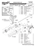
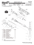
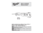
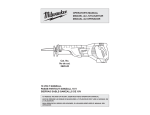
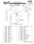
BULLETIN NO. SERVICE PARTS LIST 54-40-7000 REVISED BULLETIN SPECIFY CATALOG NO. AND SERIAL NO. WHEN ORDERING PARTS DATE Aug. 2006 ® CORDLESS SAWZALL 0719-20 CATALOG NO. 67 WIRING INSTRUCTION STARTING SERIAL NO. A56A 26 4 66 NOTES: Seal side of bearing (2) to face armature (15). 14 1460 62 SEE REVERSE SIDE 61 00 63 42 0 39 65 68 69 Stamped arrows (>>) on field casing (16) to face armature fan (11). EXAMPLE: Component Parts (Small #) Are Included When Ordering The Assembly (Large #). 24 68 Concave side of connector block cover (23) to face connector block (19). 30 31 34 64 24 35 36 41 31 7 41 69 8 35 13 34 19 23 17 30 23 25 38 37 3 43 27 46 28 2 32 9 10 18 FA SID N E 36 16 >> 59 45 47 29 LUBRICATION Place 1/2 oz. of type "Y" grease, No. 49-08-5270, in diaphragm cavity near the needle bearing. 48 8 60 PART NO. 02-04-0719 02-04-5130 02-50-2150 05-88-0302 05-88-8309 06-82-5363 06-82-7253 06-82-7261 06-82-7276 12-20-0719 28-14-0997 16-01-2121 18-01-2120 22-20-0860 22-32-0400 22-56-0975 28-28-0719 31-05-0719 -------------31-15-0511 31-44-0718 31-44-0719 31-50-0019 31-52-0090 34-60-0920 34-60-3680 40-50-0161 40-50-8840 42-24-0620 42-50-0076 42-50-0077 44-60-0626 44-60-1635 44-66-0880 45-12-0999 45-16-0645 45-22-0081 45-24-0719 45-88-1555 40-50-8850 42-12-0155 32-40-0719 43-06-0685 43-06-0676 43-78-0525 36-92-0501 61 50 33 62 52 53 22 54 21 56 57 5 FIG. 1 2 3 4 5 7 8 9 10 13 14 15 16 17 18 19 21 22 23 24 25 26 27 28 29 30 31 32 33 34 35 36 37 38 39 40 41 42 43 44 45 46 47 48 49 50 55 49 1 Place 2-1/2 oz. of type "L" grease, No. 49-08-4175, in cavity in front of bearing plate in the gearcase. Place a heavy coat of Type "X" contact grease, No. 49-08-5000, in/on terminals of wires #68 and #69 after installing into connector block (19) but prior to snapping on the cover (23). 40 51 44 15 DESCRIPTION OF PART NO. REQ. Ball Bearing (1) Ball Bearing (1) Needle Bearing (1) K50 x 60mm Washer Hd. PT Screw (2) K50 x 35mm Washer Hd. PT Screw (1) 8-32 x 1 Washer Hd. Taptite T-20 Screw (2) 8-32 x .38 Taptite T-20 Screw (3) 6-19 x .687 Slotted Plastite T-15 Screw (4) 6-19 x 1.00 Slotted Plastite T-15 Screw (2) Service Nameplate Kit (1) Gearcase (1) Service Armature (1) Service Field (1) Brush Tube (2) Brush Spring Clip (2) Connector Block Assembly (1) Diaphragm (1) Baffle (1) Connector Block Cover (1) Spring Cover (1) Right Handle Half (1) Left Handle Half (1) Motor Housing (1) Shoe Release Lever (1) External Retaining Ring (1) Retaining Ring (1) Torsion Spring (1) Brush spring (2) Rear Spindle Bearing (1) Front Cam (1) Rear Cam (1) Lock Pin (1) Shoe Pin (1) Shoe Retainer (1) Gearcase Insulator (1) Shoe Assembly (1) Sleeve (1) Lock Off Lever (1) Washer (1) Disc Spring (1) Wobble Shaft Axel (1) Intermediate Gear (1) Metal Plate (1) Bronz Plate (1) Drive Hub (1) Wobble Shaft (1) FIG. 51 52 53 54 55 56 57 58 59 60 61 62 63 64 65 66 67 68 69 52 PART NO. 34-80-2600 02-04-1510 30-72-0085 34-60-1315 06-82-7253 44-86-0055 45-36-1445 06-55-3790 38-50-0680 ------------------------------------------42-52-0380 14-46-1011 23-66-1719 22-18-1719 22-18-0719 23-94-0016 23-94-0015 58 DESCRIPTION OF PART Internal Retaining Ring Ball Bearing Wobble Plate Retaining Ring 8-32 x 3/8" Pan Hd. Slt. Taptite T-20 Bearing Retainer Spacer 5/16-24 Spinlok Hex Nut Reciprocating Spindle Front Spindle Bearing Felt Seal Washer Bearing Cap Steel Quik-Lok Blade Clamp Kit Switch Assembly Carbon Brush Assembly - Black Carbon Brush Assembly - Red Leadwire Assembly - Black Leadwire Assembly - Red NO. REQ. (1) (3) (1) (1) (2) (1) (1) (1) (1) (1) (2) (2) (1) (1) (1) (1) (1) (1) (1) NOTES: Press rear spindle bearing (33) flush to -.030 from front exterior face in diaphragm boss (21). Torque spinlok hex nut (58) to 180 in./lbs. to 210 in./ lbs. Retaining ring (51) is to be installed with the beveled side away from the bearing (52). Press front spindle bearing (60) flush to .015 below interior surface of gearcase (14). Needle bearing (3) is to be pressed from the open end flush to ±.005 to face of bearing boss of diaphragm (21). Wobble plate retaining ring (51), to face wobble shaft (50) in assembly. Remove brush tubes (17) prior to removing armature assembly (15) from motor housing (27). Install brush tubes (17) into motor housing (27) only after armature assembly (15) has been secured into motor housing (27). MILWAUKEE ELECTRIC TOOL CORPORATION 13135 W. LISBON RD., BROOKFIELD, WI 53005 Drwg. 4 REMOVING THE STEEL QUIK-LOK® BLADE CLAMP • Remove external retaining ring (30) and pull front cam (34) off. • Pull lock pin (36) out and remove remainder of parts and discard. Ensure drill point exists in bottom of pin hole. Leg REASSEMBLY OF THE STEEL QUIK-LOK® BLADE CLAMP Outer Slot 36 • Coat new lock pin with powdered graphite. • Hold tool in a vertical position. • Place spring cover (24) onto spindle. • Slide torsion spring (31) onto spindle with spring leg on hole side of spindle. • Slide sleeve (41) onto spindle aligning hole on sleeve with hole in spindle. • Slide rear cam (35) over sleeve until it bottoms on sleeve shoulder, ensure spring leg inserts into hole in rear cam. • Rotate rear cam in the direction of the arrows located on spring cover until there is clearance for lock pin (36) to be inserted into sleeve/spindle holes. Insert lock pin. • Align front cam (34) inner ribs with rear cam outer slots and slide front cam onto sleeve until it bottoms. Retaining ring (30) groove should be completely visible. • Attach retaining ring by separating coils and inserting end of ring into groove, then wind remainder of ring into groove. Ensure ring is seated in groove. • Blade clamp should rotate freely. During normal usage, debris may not allow blade clamp to rotate freely. The use of spray lubricant can help free blade clamp. In extreme conditions, follow these instructions to remove, clean and reassemble blade clamp. 24 30 31 41 35 34 Carbon brush wires #1 and #2 are to be positioned with the wire crimps in the traps. WIRING INSTRUCTIONS Route carbon brush wires #1 and #2 into wire traps, as shown. POSITION WIRES ON SWITCH TABS AND SOLDER, AS SHOWN. 2 1 -- 2 + 1 1 1 2 -- ! WARNING + SWITCH POLARITY SENSITIVE If wired incorrectly, switch will be damaged and destroyed! 4 3 Place a heavy coat of Type "X" contact grease, No. 49-08-5000, in/on terminals of wires #3 and #4 after installing into connector block but prior to snapping on the connector block cover. 4 3 -- + 2 WIRING SPECIFICATIONS Wire No. 1 2 3 4 Wire Color Origin or Gauge Length Red 22-18-0719 ----- Carbon brush assembly. Black 22-18-1719 ----- Carbon brush assembly. 23-94-0015 ----- Leadwire assembly. Black 23-94-0016 ----- Leadwire assembly. Red TERMINAL DESCRIPTION Code Terminals, Connectors and 1 or 2 End Wire Preparation BULK LEAD WIRE - BULLETIN NO. 58-01-0003 Part No. Qnty.