1
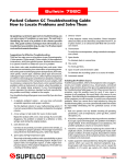
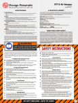
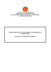
9800 0329 01 a
GB
840M
Date Code
0011L2001
Service and Repair Manual
Model 840M
2
General
For best performance hammers should be serviced at regular intervals, any indication that the hammer is not performing as specified should be
investigated to prevent any adverse damage occuring.
ALL SEALS, GASKETS, GREASE OR OTHER PARTS DEEMED NECESSARY FOR SERVICING ARE IN THE SERVICE KIT.
ALL NEEDLE ROLLER BEARINGS SHOULD BE PRESSED WITH THE ROUNDED EDGE ENTERING THE BORE FIRST, AND THE PRESS
TOOL PRESSING AGAINST THE FLAT SURFACE OF THE BEARING.
Cleaning
All mechanical parts with the exception of any sealed bearings should be cleaned in a suitable cleaning fluid. Electrical parts should be cleaned
by the use of compressed air. PRECAUTIONS MUST BE TAKEN FOR PERSONAL SAFETY THE USE OF EYE PROTECTION AND GLOVES IS
RECOMMENDED.
Inspection
All mechanical and electric parts should be inspected for wear and replaced as required.
WARRANTY AND LIABILITY STATEMENT
Use only Authorized parts. Any damage or malfunction caused by the use of unauthorized parts is not
covered by Warranty or Product Liability.
SERVICE TOOLS
All repairs may be completed with standard workshop tools and equipment.
Service and Repair Manual
Model 840M
00
3
EXAMPLE:
0 Component Parts (Small #)
Are Included When Ordering
The Assembly (Large #).
%SEE PAGE 5 FOR
ADDITIONAL
LUBRICATION AND
SERVICE NOTES
FIG.
1
4
8
10
11
12
13
14
15
16
17
22
23
26
27
28
29
30
31
32
33
34
35
37
42
46
47
50
51
52
53
63
66
86
PART NO.
9170 4650 00
9170 4672 80
9170 3253 10
9170 3252 90
9170 4650 90
9170 4651 00
9170 4651 10
9170 4651 20
9170 4651 30
9170 4651 40
9170 4651 50
9170 3253 90
9170 4652 00
9170 3252 50
9170 4666 00
9170 4665 90
9170 4652 90
9170 4653 40
9170 4653 60
9170 4654 00
9170 4654 10
9170 4668 30
9170 4654 50
9170 4654 60
9170 4655 00
9170 4655 30
9170 4655 40
9170 4655 70
9170 4655 90
9170 4656 10
9170 4656 30
9170 4672 80
9170 4657 80
9170 4673 20 ●
DESCRIPTION OF PART
NO. REQ.
Ball Bearing
(1)
Vent Kit
(1)
Pivot Nut
(1)
Pivot Bolt
(1)
K50 x 8mm Pan Hd. Plastite Screw
(1)
K35 x 8mm Pan Hd. Plastite Screw
(1)
K60 x 20mm Pan Hd. Plastite Screw
(2)
K60 x 40mm Pan Hd. Plastite Screw
(2)
K50 x 30mm Pan Hd. PT-DG Screw
(2)
K60 x 18mm Pan Hd. PT-DG Screw
(2)
K60 x 120mm Pan Hd. PT-DG Screw
(2)
Pan Hd. Cap Screw
(2)
Slotted Plastite Torx Screw
(2)
K50 x 18mm Pan Hd. Plastite Screw
(4)
Thumbwheel
(1)
Service Nameplate Kit
(1)
Electronics Assembly
(1)
Armature Kit (See Service Note)
(1)
Field
(1)
Brush Card Assembly
(1)
Blade Housing Assembly
(1)
Quik-Lok Cord Set
(1)
Switch
(1)
Crankcase Assembly
(1)
Upper Handle Mount
(1)
Module Cover
(1)
Motor Cover
(1)
Left Handle Half
(1)
Right Handle Half
(1)
Motor Housing
(1)
Rear Shroud
(1)
Vent Kit
(1)
O-Ring
(2)
Bearing Cup
(1)
(See Note)
Armature Service Note:
When servicing the armature,
use Armature Kit No. 9170 4653 40.
If the tool has a spacer in the armature
bearing bore of the gearcase, remove the
spacer and install O-Ring No. 9170 4673 00 into
the empty groove. The O-Ring is provided in the kit.
FIG.
92
93
94
95
96
100
122
123
PART NO.
9170 4653 80
9170 4666 10
9170 4660 80
9170 3254 30
9170 4654 90
9170 4661 40
9170 3254 00
9170 4662 80
DESCRIPTION OF PART
NO. REQ.
Carbon Brush Kit (Includes 2 Brushes) (1)
Brush Spring
(2)
Bellows
(1)
Isolation Module Assembly
(1)
Light Pipe
(1)
Cushion Grip
(1)
Rubber Washer
(2)
Handle Seal
(1)
Service and Repair Manual
Model 840M
4
Chamfer for barrel washers (119)
are to face to the outside,
as shown.
%SEE PAGE 5
FOR ADDITIONAL
LUBRICATION
AND SERVICE NOTES
NOTE:
Do not wash
clutch gear assembly (57). If
needed, wipe off with a dry rag.
Coat gearcase seal (62) with
lubrication prior to placement in
the gearcase (38).
Use Blue
Loctite
#242 on
screws
(24), two
places.
2
1
2
1
1
1
1
1
1
2
1
1
1
z 9170 4672 00 HAMMER SERVICE KIT
THIS KIT CONTAINS:
9170 4655 10
Cap Plug
9170 4657 40
Gearcase Seal
9170 3255 50
O-Ring
9170 4657 70
Cap Seal
9170 4658 00
O-Ring
9170 4658 20
O-Ring
9170 4673 00
O-Ring
9170 4658 30
Damping Washer
9170 4673 20
Bearing Cup
9170 4663 20
Split Sleeve
9170 4672 10
Carbon Brush
9170 4672 20
Carbon Brush
9170 4664 70
"S2" Grease - 7 oz. Tube
9170 4653 80 CARBON BRUSH SERVICE KIT
THIS KIT CONTAINS:
2
--------------Carbon Brush
FASTENER TORQUE SPECIFICATIONS (IN.LBS.)
SEATING TORQUE
FIG. NO.
MINIMUM
MAXIMUM
9
120
140
10
20
25
11
3
6
12
4
8
13
20
25
14
20
25
15
20
25
16
50
55
17
30
35
22
30
35
23
15
20
24
20
25
25
50
55
26
15
20
74
130 FT. LBS.
200 FT. LBS.
87
130 FT. LBS.
200 FT. LBS.
Switch Screws
4
6
SERVICE GREASE"S2" Grease, 7 oz. tube
No. 9170 4664 70
SERVICE CARRYING CASE
No. 9170 4669 30
Service and Repair Manual
Model 840M
FIG.
2
5
6
7
9
12
18
20
24
25
36
37
38
39
43
44
48
49
54
55
56
57
58
62
64
65
67
68
69
70
71
72
73
74
75
76
80
81
84
85
87
88
89
90
97
98
101
102
103
104
105
106
107
108
109
111
112
113
114
115
118
119
121
124
125
PART NO.
9170 3254 90
9170 4650 40
9170 4672 80
9170 3255 20
9170 4650 70
9170 4651 00
9170 4663 20
9170 3258 10
9170 3254 60
9170 4652 20
9170 4653 30
9170 4654 60
9170 4671 70
9170 4652 80
9170 4655 10
9170 4655 20
9170 4666 30
9170 3258 00
9170 4656 50
9170 4656 70
9170 3258 60
9170 4666 40
9170 4657 10
9170 4657 40
9170 3255 50
9170 4657 70
9170 4657 90
9170 4658 00
9170 4658 10
9170 4658 20
9170 4658 30
9170 3257 80
9170 4658 60
9170 4658 70
9170 4659 00
9170 4659 10
9170 3259 30
9170 3258 80
9170 3258 50
9170 3258 70
9170 4660 30
9170 4666 50
9170 4660 50
9170 3257 70
9170 3259 10
9170 4653 10
9170 4661 60
9170 4661 70
9170 4661 80
9170 3259 20
9170 3258 20
9170 3258 40
9170 4662 20
9170 3257 60
9170 3255 10
9170 3258 30
9170 4663 10
9170 4663 30
9170 4663 60
9170 4664 00
9170 4664 10
9170 4664 30
9170 3257 90
9170 4672 80
DESCRIPTION OF PART
NO. REQ.
Ball Bearing
(2)
Ball Bearing
(1)
Vent Kit
(1)
Needle Bearing
(1)
M6 Socket Head Cap Screw
(4)
K35 x 8mm Pan Hd. Plastite Screw
(1)
Split Sleeve
(2)
Dowel Pin
(1)
Slotted Taptite Torx Screw
(2)
K50 x 22mm PT-DG Screw
(4)
SDS-Max Nose Service Assembly
(1)
Crankcase Assembly
(1)
Gearcase Service Kit
(1)
Crankshaft Assembly
(1)
(2)
● 5/8 Cap Plug
Screw Cap
(1)
Depth Rod Mount Assembly
(1)
Side Handle Housing
(1)
Main Shroud
(1)
Locking Ring
(1)
Spacer
(1)
Clutch Gear Assembly
(1)
Drive Gear
(1)
(1)
● Gearcase Seal
(2)
● O-Ring
(1)
● Capseal
O-Ring
(1)
(1)
● O-Ring
O-Ring
(1)
(1)
● O-Ring
(1)
● Damping Washer
External Retaining Ring
(1)
Retaining Ring
(1)
Spindle
(1)
Shift Spring
(1)
Compression Spring
(1)
Key Spring
(1)
Side Handle Band
(1)
Chuck Collar
(1)
Collar
(1)
Barrel
(1)
Shift Disk Assembly
(1)
Spring Flange
(1)
Side Handle Assembly
(1)
Keys
(2)
Shift Knob Assembly
(1)
Wrist Pin
(1)
Piston
(1)
Ram
(1)
Key Retaining Ring
(1)
Band Retainer
(1)
Seal Retaining Ring
(1)
Shift Ring
(1)
Depth Gauge Rod
(1)
Connecting Rod Assembly
(1)
Dust Seal
(1)
Felt Seal
(1)
Spindle Seal
(1)
Retaining Slug
(1)
SDS-Max Striker
(1)
Washer
(2)
Barrel Washer
(2)
Washer
(1)
Wave Washer
(1)
Vent Kit
(1)
NOTE: Check the clutch torque. Clutch must slip at 40 to 50 ft.lbs.
at the spindle, checked clockwise as viewed from the
front of the tool.
5
Press Needle Bearing (7)
in Connecting Rod (109)
so that the same amount
sticks out on both sides
of the Rod.
Press Needle
Bearing (6) into
Crankcase (37)
flush with the top
of the crankcase
casting,
as shown.
LUBRICATION NOTES: (TYPE "S2" GREASE, NO. 9170 4664 70)
Fill Piston (102) with "S2" grease and assemble to Connecting Rod (109)
with the Wrist Pin (101). Front surface
of Piston (102) and the Ram (103) is
to be free of grease.
Lubricate the O-Ring (68)
with grease.
Lightly coat the inside of the Barrel (87)
with grease prior to assembly.
Lightly coat the
inside bore of the
Spindle (74) prior to
the insertion of the
Striker (115).
%SEE PAGE 6
FOR ADDITIONAL
SERVICE NOTES
Prior to assembly,
apply a light coat of grease
to the Gearcase Seal (62) and
O-Rings (63, 64, 67, 68 and 70).
Service and Repair Manual
Model 840M
6
Press metal insert of
fan to here.
30
30
3
Press fan (3) onto armature (30)
such that the metal insert of the fan
bottoms against the fan journal
shoulder of the armature shaft.
After the armature assembly (30) is
installed into the tool, the bearing cup
(86) is to be placed on the rear armature
bearing (1), (already pressed onto the
armature shaft), prior to assembling the
motor cover (47) to the tool.
1
86
NOTE: Do not dislodge the bearing cup
from the bearing during assembly.
Service and Repair Manual
Model 840M
7
NOTE:
Module wires #3 and #4
are not polarity sensitive.
WIRING SPECIFICATIONS
TERMINAL DESCRIPCode
Wire
No.
Wire
Color
Origin or
Gauge
Length
1
Black
Blade Hsg.
-----
Component of blade housing assembly.
2
White
Blade Hsg.
-----
Component of blade housing assembly.
3
Black
Elect. Mod.
-----
Component of electronics module. Strip 1/4" for T1.
4
Black
Elect. Mod.
-----
Component of electronics module. Strip 1/4" for T1.
Part No.
Qnty.
Terminals, Connectors and 1 or 2 End Wire Preparation
T1
9170 4666 90
2
Service and Repair Manual
Model 840M
ELECTRICAL TESTING
Electrical test
Before assemby all electrical parts MUST be checked for safety, and that they conform to specification.
Testing the Armature (Flash Testing)
A
Armature shaft to lamination pack
1500 Volts (min)
B
Lamination pack to commutator
1200 Volts (min)
C
Armatuure shaft to commutator
3000 Volts (min)
ELECTRICAL PERFORMANCE TEST READINGS
ARMATURES
MODEL
110V
120V
220V-240V
840M
.440/.506 Ohms
.440/.506 Ohms
1.283/1.477 Ohms
840M
FIELD COILS
120V
110V
.349/.401 Ohms
.349/.401 Ohms
220V-240V
1.339/1.54 Ohms
PERFORMANCE
840M
110V
Running No Load
120V
4.5/6.5 Amps
4.5/6.5 Amps
CLUTCH SLIP
Measured on disassembly/assembly 40/50ft lbs 47/61Nm. (Non Electrical Test)
Note: On all test readings + or -5% of figures shown is acceptable.
220V-240V
2.9/4.4 Amps
8
Service and Repair Manual
Model 840M
9
WARNING
LETHAL VOLTAGES PRESENT!!
IMPORTANT
On completion of the assembly, the unit must be flash tested at 4000 volts.
Flash Test
1.
With the breaker completely assembled and with the switch "ON", apply 2000 volts initially and increase rapidly to 4000 volts between the main
casting and one of the pins of the plug on the power supply cord. Apply test to both live and neutral pins.
2.
The full voltage of 4000 volts should be maintained without breakdown or flashover for a few seconds.
3.
If the armature has been tested, remove the carbon brushes before carrying out the test, (thus avoiding overstressing the armature insulation
system).
4.
The test voltage must be applied between the main casting and each live pin of the plug in succession.
Running Test
1.
Ensure the unit is switched "ON" before testing. Operate the unit for approx. 10 minutes at half voltage for initial 'bedding in' of the carbon brushes
followed by full operational voltage. Compare readings with Performance Data.
FAULT FINDING
With the aid of the Fault Finding chart (below) the source of any malfunction may be quickly identified and repaired.
Sickla Industriväg 1A, S-105 23
Nacka Sweden
Telephone: +46 (0) 8 743 9600 Fax: +46 (0) 8 743 9650
9800 0329 01 a
54-24-1025 Drwg. 5
08/06